

SPECTRA and SPECTRA
X Light Engine
®
Instruction
Manual
! !
Lumencor, Inc. Document Number 52-10060, Rev. C www.lumencor.com

!
Regulatory Models
Lumencor utilizes regulatory model names for all certified and CE marked products. The regulatory model names are
traceable to all regulatory documentation, third party reports and certifications.
“Regulatory Model: Spectra” is used as a representative model for all certified and CE marked Spectra Products.
Emissions
This equipment has been tested and found to comply with the limits of EMC directive 2014/30/EU. These limits are designed to provide reasonable protection against harmful interference when the equipment is operated in a commercial
environment. This equipment generates, uses, and can radiate radio frequency energy and, if not installed and used in
accordance with the instruction manual, may cause harmful interference to radio communications.
Safety Certifications
TUV SUD America, CB Certification (IEC 61010-1:2010)
TUV SUD America, NRTLus Certification (UL 61010-1:2012-05)
TUV SUD America, cNRTL Certification (CAN/CSA-C22.2 No. 61010-1:2012)
TUV SUD America, EN Certification (EN 61010-1:2010)
Underwriters Laboratories (UL), CB Certification (IEC 62471:2006)
CE Marking
Low Voltage Directive (2014/35/EU)
EMC Directive (2014/30/EU)
RoHS Directive (2011/65/EU)
REACH Regulation (EC) No. (1907/2006/EC)
EU Declarations of Conformity can be found at http://lumencor.com/company/regulatory-compliance/
Lumencor, Inc.
14940 NW Greenbrier Parkway
Beaverton, OR 97006
T 503.213.4269
www.lumencor.com
Document Number 52-10060, Rev. C
SPECTRA and SPECTRA X Instruction Manual" !1

Table of Contents
1.
Introduction"
2.
Precautions and Warnings"
3.
Installation and Operating Instructions"
4.
Spectral Output"
5.
Routine Maintenance and Trouble Shooting"
6.
Customer Support"
7.
Product Specifications"
8.
Warranty"
SPECTRA and SPECTRA X Instruction Manual" !2

!
1. Introduction
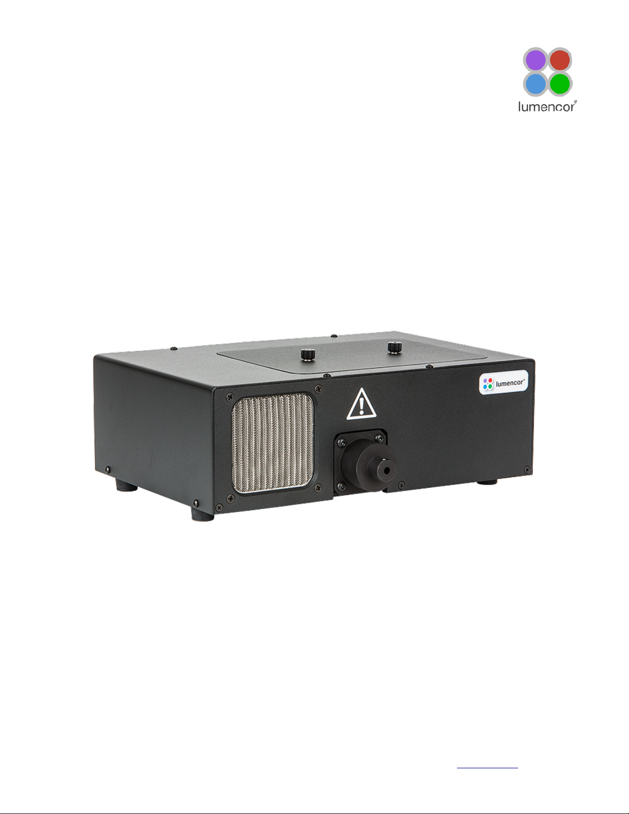
Lumencor SPECTRA and SPECTRA X light engines are designed for laboratory use by bioanalytical researchers and/or
developers of life science instrumentation. The SPECTRA provides 3, 4, 5, 6 or 7 spectrally discrete, bright, controllable
light outputs directly to a sample; or in the case of fluorescence microscopy, to the objective. Each of the colors is
produced by an independent module that has been optimized to produce a precise set of wavelengths. The SPECTRA X
provides 6 solid state light sources whose outputs are refined by user-exchangeable bandpass filters. Light output can
be coupled into a liquid light guide (LLG) or SMA-terminated optical fiber via exchangeable output adapters. This manual
covers all SPECTRA and SPECTRA X models.
The SPECTRA and SPECTRA X can be controlled by serial commands to the RS-232 port from Lumencor’s Light Engine
Control Pod accessory (part number 83-10007), from a computer workstation running 3rd party image acquisition control
software or from Lumencor’s SPECTRA control GUI. The GUI controls only the light engine. Third-party image
acquisition control software is required for co-ordinated operation of the light engine with cameras and other peripherals.
The Light Engine Control Pod accessory controls light source selection, on/off switching and output intensity using two
push buttons and a rotary dial in combination with menus and status displays on a built-in screen.# A second USB port
on the pod allows pass-through control of the light engine from computer workstations. The SPECTRA and SPECTRA X
are also equipped with TTL control interfaces. TTL provides source selection and light output on/off switching but not
intensity control. However TTL signals elicit much faster responses than serial commands. #TTL control signals are
typically derived from hardware peripherals such as cameras or digital acquisition (DAQ) cards.
2. Precautions and Warnings {Précautions et mises en garde}
A few simple practices will ensure trouble-free operation for the life of the light engine.
Les quelques règles simples suivantes permettront d’assurer un fonctionnement fiable pendant toute la durée de service
de la source lumineuse.
Safety Instructions:
Please read and follow all safety instructions provided BEFORE using your new SPECTRA. Failure to comply with the
safety instructions may result in fire, electrical shock, or personal injury and may damage or impair protection provided by
equipment. Please save all safety instructions.
Instructions de sécurité:
Veiller à lire et à respecter toutes les instructions de sécurité fournies AVANT d’utiliser le nouveau SPECTRA afin d’écarter les risques d’incendie, de décharge électrique, de blessure corporelle et de possibles dommages ou défaillance de la
protection offerte par l’appareil. Conserver toutes les instructions de sécurité.
Safety Definitions {Définitions relatives à la sécurité}:
Warning: Statements identify conditions or practices that could result in personal injury.
Avertissement: déclarations qui identifient des situations ou des pratiques susceptibles d’entraîner des
blessures corporelles.
Caution: Statements identify conditions or practices that could result in damage to your equipment.
Attention: déclarations qui identifient des situations ou des pratiques susceptibles d’endommager le matériel.
SPECTRA and SPECTRA X Instruction Manual" !3

Safety Items {Mesures de sécurité}:
Warning: DO NOT use an unapproved power supply. The Lumencor supplied external power supply is
recommended for use with the SPECTRA light engines. Alternate 24VDC/5A power supplies may be used for the
standard SPECTRA (no simultaneous outputs) or alternate 24-30VDC/7.9A power supplies may be used for SPECTRA
X and SPECTRA S (simultaneous outputs) but it is imperative that it has output over-current protection, as the power
input of the SPECTRA is not fused. The equipment is required to be supplied by a properly approved/certified DC power
source meeting the minimum electrical ratings of the product. Connect the AC power cord to a receptacle with a
protective safety (earth) ground terminal.
Avertissement!: NE PAS utiliser une alimentation électrique non homologuée. Il est conseillé d’utiliser
l’alimentation électrique externe fournie par Lumencor avec les sources lumineuses SPECTRA. Il est possible d’utiliser
une autre alimentation électrique continue 24#V/5#A avec la source SPECTRA standard (pas de sorties simultanées) ou
une autre alimentation électrique continue 24-30#V/7,9#A avec les sources SPECTRA X et SPECTRA S (sorties
simultanées), toutefois il est impératif qu’elle présente une protection de sortie contre les surintensités, car l’entrée
d'alimentation du SPECTRA ne comporte pas de fusible. L'équipement doit être fourni par un / certifié DC réunion de
source d'alimentation correctement approuvé les ratings électriques minimales du produit. Brancher le cordon électrique
sur une prise de courant protégée par une borne de terre.
Warning: DO NOT look into the output of the light engine. The brightness of this light source is higher than most
commercial lighting fixtures and is required to couple directly into a microscope or other bioanalytjcal instrument.
Avertissement: NE PAS regarde directement la sortie de la source lumineuse. L’intensité lumineuse de cette
source est supérieure à celle de la majorité des appareils d’éclairage disponibles dans le commerce et est conçue pour
un raccordement direct à un microscope ou autre appareil de bioanalyse.
Warning: DO NOT turn on the light without!the output end of the light guide safely!directed!into an enclosed
optical path. #The light output at the end of the light guide has the potential to get very hot and may cause burns or
fire if used in a way other than directed by this instruction guide."
Avertissement: NE PAS allumer la lumière sans l'extrémité de sortie du guide de lumière dirigée en toute
sécurité dans un chemin optique fermé. La sortie de la lumière à la fin du guide de lumière a le potentiel de de-
venir très chaud et peut causer des brûlures ou d'incendie si elle est utilisée d'une manière autre que la direction de
ce guide d' instruction."
RISK GROUP 3
Warning: UV emitted from this product. Avoid eye and skin exposure to unshielded product.
Warning: Possibly hazardous optical radiation emitted from this product. Do not look at operating lamp. Eye injury may
result.
GROUPE DE RISQUE 3
Avertissement: UV émis par ce produit . Évitez les yeux et la peau exposition au produit non blindé.
Avertissement: Rayonnement optique Peut-être dangereux émis par ce produit . Ne regardez pas la lampe d'expl-
oitation. Une blessure oculaire peut entraîner.
SPECTRA and SPECTRA X Instruction Manual" !4

!
Caution: DO NOT open the unit. There are no serviceable parts inside and opening the light engine enclosure will void
the manufacturer’s warranty.
Attention: NE PAS ouvrir l’appareil. Il ne contient aucune pièce réparable et l’ouverture de son boîtier a pour effet
d’annuler la garantie.
Caution: DO NOT connect a video cable to the TTL input enable port. Although the connector might look
compatible, this input is not intended to be driven by a video signal.
Attention: NE PAS raccorder un câble vidéo au port d’activation d’entrée TTL. Bien que le connecteur puisse
paraître compatible, cette entrée n’est pas conçue pour être contrôlée par un signal vidéo.
Caution: DO NOT set liquids on the light engine. Spilled liquids may damage your light engine.
Attention: NE PAS placer de liquide sur la source lumineuse. Les liquides renversés peuvent endommager la
source lumineuse.
Caution: DO NOT drop the light engine. It contains glass optical components that could be damaged or misaligned
by the shock produced by a drop onto a hard surface.
Attention: NE PAS laisser tomber la source lumineuse. Elle contient des composants optiques en verre susceptibles d’être endommagés ou désalignés par le choc résultant d’une chute sur une surface dure."
DISCLAIMER: Lumencor shall not be liable for injury to the user or damage to the product resulting from the
SPECTRA being used in a way for which it was not intended and in complete disregard for all posted safety
precautions and warnings.
AVIS DE NON-RESPONSABILITÉ: Lumencor décline toute responsabilité pour les blessures corporelles ou
les dommages au produit résultant d’une utilisation du SPECTRA autre que celle prévue et du mépris total de
toutes les mesures de sécurité et mises en garde affichées.
3. Installation and Operating Instructions"
3.1 Contents
The SPECTRA family of light engines all ship with the following list of standard
components.
1.
SPECTRA or SPECTRA X light engine, configured with four, five, six or seven
output channels. The installed excitation filter configuration will be listed on the
certificate of conformance supplied with the unit (Figure 1).
2.
A 24V/9.2A power supply (Lumencor part no. 27-10019) ships with SPECTRAYYY- Z and a 28V/7.9A power supply (Lumencor part no. 27-10003) ships with
SPECTRA X-YYY-SZ.
3.
A region-specific 6ft AC power cord for the power supply (see adjacent table).
SPECTRA and SPECTRA X Instruction Manual" !5
AC Power Cords
Region
Part Number
North America
29-10002
Europe
29-10005
United Kingdom
29-10004
Israel
29-10008
Australia/New Zealand
29-10024

4.
A USB-to-RS232 cable (Lumencor part no. 29-10011) for serial communication with computer workstations or
the Light Engine Control Pod.
5.
Output adapter for light delivery via 3 mm diameter liquid light guide or SMA-terminated optical fiber (Figure 2).
3.2 Installation"
When setting the SPECTRA or
SPECTRA X up for use, be sure
to place the unit on a hard
surface and avoid blocking or
restricting airflow at the air intake
(front panel, left of the light output
port) or exhaust ports (on the
underside of the unit). Restricting
the airflow will cause the unit to
operate at elevated temperatures
and will result in decreased
product life and/or premature
failure. Position the unit in such
an orientation that allows
unrestricted access to the DC
power connector. In an emergency, you may need to disconnect power to the unit quickly.
To install the output adapter, remove the shipping cover from the light output port on the front panel by extracting the
four M4 fixing screws. Insert the output adapter (Figure 2) into the output port and secure it with an M4 fixing screw in
SPECTRA and SPECTRA X Instruction Manual" !6
SPECIMEN
Figure 1. Specimen certificate of conformance for
SPECTRA X Light Engine.
Figure 2. Output adapters for SPECTRA and SPECTRA X light engines.

!
each corner. Retain the light output port shipping cover and re-install it in the event that the light engine requires
transportation. Attach the optical fiber or liquid light guide to the output adapter. In the case of liquid light guides, secure
the tip of the light guide in the output adapter using the set screw provided (Figure 2). Prior to activating light output, be
sure the output end of the light guide or optical fiber is safely directed into an enclosed optical path (e.g. microscope
input collimator or a beam dump). Do not bend the light guide beyond its specified minimum bending radius (40
mm or 1.6 inches). Extreme bending of the light guide may cause permanent deformation, resulting in decreased light
transmission.
SPECTRA light engines have bandpass filters associated with each light source. These filters are part of the order
specification and are not user-exchangeable. SPECTRA X light engines have user-exchangeable filters installed in
SPECTRA and SPECTRA X Instruction Manual" !7
Figure 3. Spectra X filter locations
Figure 4. Spectra X filter paddle
removable paddles which the user can access once the top cover retained by two thumb screws is removed (Figure 3).
The paddles accept standard 25 mm diameter filters. A set screw recessed in the body of the paddle engages the
perimeter mounting ring of the filter to secure it in place (Figure 4). A listing of standard bandpass filters available for
installation in SPECTRA and SPECTRA X light engines can be found at http://lumencor.com/products/filters-for-spectra-
x-light-engines/
SPECTRA and SPECTRA X Instruction Manual" !8
RS-232 (DB9) Connector Pin Definitions
Pins
Definition
DC Characteristics
1, 2, 3, 4, 6, 7, 8
DCD, RXD, TXD, DTR, D3R, RTS,
CTS
VCC = 5.0V!
V
ilow
(max) = 0.8V, V
ihigh
(min) = 2.4V,
I
ilow
= 0.5mA, I
ihigh
= 1.0μA
5
Gnd
9
N/C
This port conforms to standard RS-232 interface protocol.
TTL (DB15HD) Connector Pin Definitions
Pins
Definition
DC Characteristics
1, 2, 3, 11, 12, 13
Red, Green, Cyan, Teal, Blue, UV
respectively
VCC = 5.0V!
V
ilow
(max) = 1.5V, V
ihigh
(min) = 3.3V,
I
ilow
= 0.5mA, I
ihigh
= 1.0μA
15 - Green/Yellow
Excitation Filter Select!
Vin = H => Green, Vin = L => Yellow
VCC = 5.0V!
V
ilow
(max) = 1.5V, V
ihigh
(min) = 3.3V,
I
ilow
= 0.5mA, I
ihigh
= 1.0μA
6, 7, 8, 10
Gnd
4, 9, 14
N/C
TTL polarity may be set ACTIVE = HIGH or ACTIVE = LOW. This setting is part of the order
specification provided by the customer.
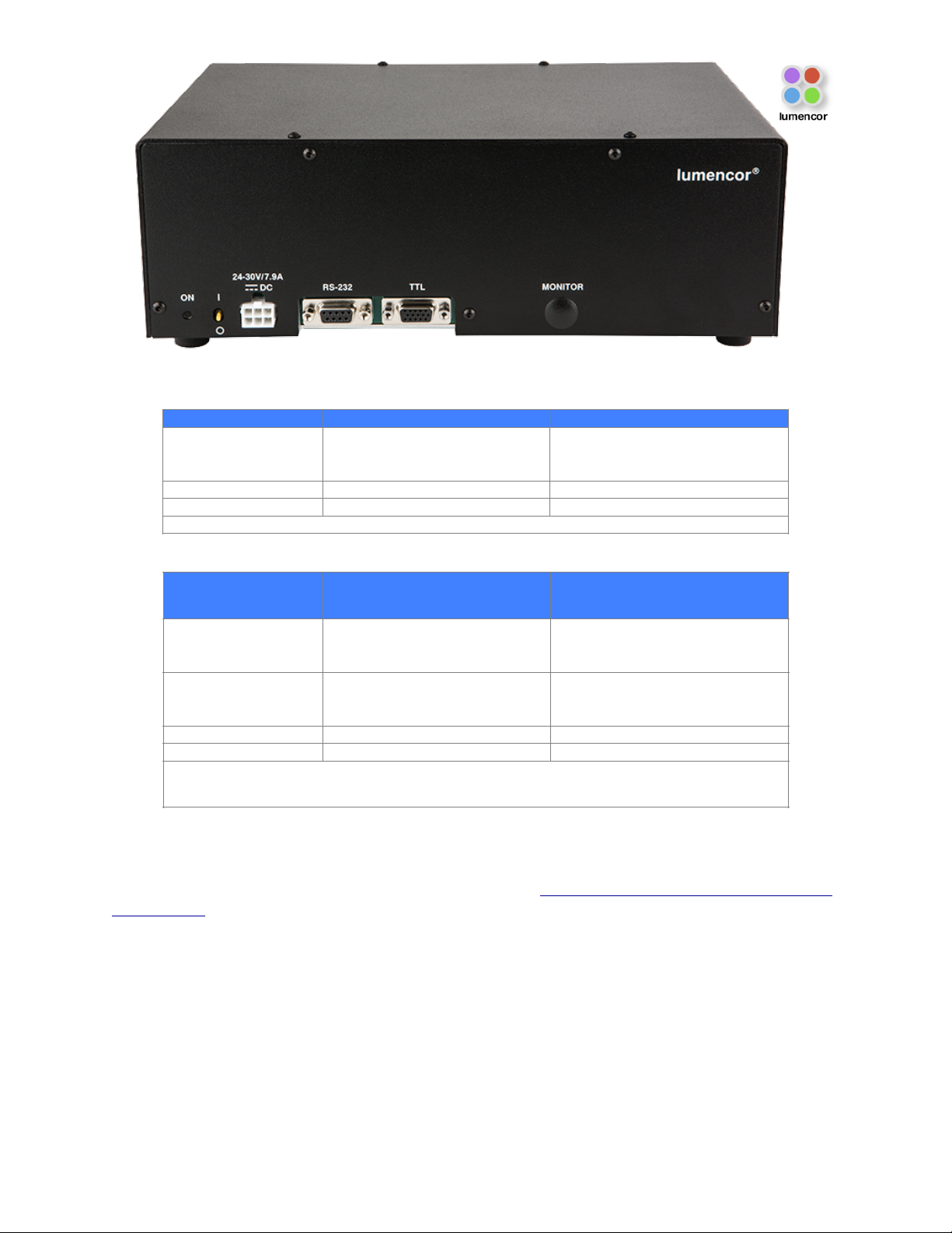
Figure 5. Control interface connections on SPECTRA light engine rear panel.

!
3.3 Operation Using the Light Engine Control Pod"
1.
Move the master power switch on the lower left of the SPECTRA rear panel (Figure 5) to the ON position. A
green LED next to the switch indicates that power to the light engine is ON.
2.
Connect the USB A port of the light engine control pod accessory (83-10007) to the RS-232 port on the
SPECTRA (Figure 5) using the USB-to-RS-232 cable (29-10011). Connect the USB B port of the control pod
to a USB A port on a host computer [1].
3.
Press and hold the right button on the pod until a menu of light engines appears. Turn the rotary dial to select
“SPECTRA” from the menu. Press the right button again to return to the main (0–100 analog intensity) display
screen.
4.
Before turning the light output on, be sure the output end of the light guide or optical fiber is safely directed into
an enclosed optical path (e.g. microscope input collimator or a beam dump).
5.
Press the left button to select the desired color channel. Successive presses will cycle through the available
color channels.
6.
Press the right button to turn the selected light source on [2]. Adjust the output intensity using the rotary dial.
Press the right button again to turn the selected light source off.
7.
Press and hold the left button to view a digital rendition of the intensity setting [3,4]. Press the right button to
return to the main display screen.
8.
Serial commands sent from a host computer to the USB B port of the control pod will automatically switch the
pod from local to pass-through mode, indicated by the message “PC pass through mode active” shown on the
pod display screen. Local command mode is disabled as long as pass-through mode remains active.
9.
To quit pass-through mode and return to local command mode, press the right button on the pod twice [5].
10.
Further details of control pod operation are provided in a downloadable instruction sheet.
Notes
[1] When configured for pass-through operation, the host
computer supplies electrical power to the pod. The pod will
turn on when the connection is made. For stand-alone
operation (no pass-through), connect a DC power supply
(5V/500mA) to the USB B port of the pod.
[2] There is no warm-up time; the light engine output
stabilizes less than 1 second after the light output is switched
on. Light output can be switched off during intervals when it
is not required for active viewing or data collection. After light
output is switched off, the cooling fan will continue to run for
5 minutes, after which it will automatically stop until light
output is turned back on.
[3] Output intensity can be set from 0–100% in 1% increments;
however operation in the 0–5% range is not recommended.
[4] The current intensity settings are internally stored. When the
pod is powered down, the settings are retained and will be restored at the next restart.
[5] Changes to light output ON/OFF status and intensity level made on the host computer during pass-through
operation will be automatically replicated in the pod settings.
SPECTRA and SPECTRA X Instruction Manual" !9
Figure 6. USB connectors on the rear of
the light engine control pod.

3.4 Operation Using Computer Workstation"
1.
Although the following instructions specify Lumencor’s SPECTRA GUI, operations using third-party image
acquisition control software that provide co-ordinated operation of the light engine with cameras and other
peripherals are generally similar.
2.
Operation and installation of the SPECTRA GUI requires a computer running the Windows operating system
with a free USB port.
3.
Download the zip file for the SPECTRA GUI INSTALLER from http://lumencor.com/resources/documentation-
software/.
4.
Unzip the file and run setup.exe to install the SPECTRA GUI.
5.
Connect the USB A-to-RS-232 cable between the computer and the RS-232 serial port on the SOLA (Figure
5).
6.
Successful installation is indicated by the appearance of “USB Serial Port (COM #)” under the “Ports (COM
&LPT)” tab in the Windows Device Manager. If the virtual COM port (VCP) is not registered by the operating
system, download and install the VCP driver from http://lumencor.com/resources/documentation-software/.
7.
Connect the DC power supply to the SPECTRA.
8.
Check that the liquid light guide or optical fiber is securely connected to the output adapter on the front panel
and that the output end is safely directed into an enclosed optical path (e.g. microscope input collimator or a
beam dump).
9.
Toggle the power switch on the rear panel to the ON position. The green LED next to the switch (Figure 5)
indicates that power to the light engine is ON.
10.
Run the GUI by going to the Program Menu and selecting LLE 7CH GUI.
11.
In the COM pulldown menu (GUI window, upper right), select COM # assigned to USB-Serial port.
12.
Press the “INIT” button in the GUI.
13.
The computer should now have control of the SPECTRA. In the GUI window, a graduated slider controls the
output intensity for each component light source [1,2]. The ON-OFF button below each intensity slider turns
light output from the selected source on or off.
14.
The G/Y button selects green or yellow light output from SPECTRA light engines. Green output is the default
selection on start up. For SPECTRA X light engines, this control is inactive and green/yelllow output selection is
accomplished by manual interchange of filters (Figure 3).
15.
There is no warm-up time; the light engine output stabilizes less than 1 second after the light output is switched
on. Light output can be switched off during intervals when it is not required for active viewing or data
collection. After light output is switched off, the cooling fan will continue to run for 5 minutes, after which it will
automatically stop until light output is turned back on.
Notes
[1] Output intensity can be set from 0–100%; however operation in the range 0–5% is not recommended.
[2] Setting the intensity slider to zero is not functionally equivalent to turning light output off using the ON-OFF button. In
this condition, the fan will continue to run as the light sources are still energized, even though their output may not be
detectable.
3.5 TTL Interface"
The TTL interface provides users with a faster method of switching color channel outputs on and off. Individual TTL lines
are provided for each color channel (Figure 5). These can be conveniently addressed using an accessory BNC breakout
cable (Lumencor part number 29-10015 or 29-10080) connected to the rear panel DB15 TTL port. Note that TTL and
serial on/off commands have a logical OR relationship. Therefore source on/off controls on the light engine control pod,
in the SPECTRA GUI or in third-party image acquisition control software must be set in the “OFF” state when using TTL
control. The TTL interface does not control source output intensity, which remains under serial (RS-232) control. TTL
polarity (ACTIVE = HIGH or ACTIVE = LOW) is factory set according to order specifications.
SPECTRA and SPECTRA X Instruction Manual" !10

!
3.6 Metered Dosage Operation"
Open loop and closed loop output monitoring and feedback systems are available as optional add-ons for SPECTRA
and SPECTRA X light engines. These systems consist of a modified output adapter that directs a small fraction of the
light output to an onboard reference photodiode, together with supporting signal processing electronics. For open loop
monitoring , the reference signal is output to a rear panel BNC connector (Figure 7) for external display or processing. In
closed loop operation, activation of the selected light source starts an onboard counter that accumulates the active
reference count from the photodiode and compares it to a control count value input by the user. When the reference
count reaches the control value (i.e. when the metered light dose has been delivered), the light output automatically shuts
off. All closed loop metered dosage functions are controlled from a serially connected computer. A Windows GUI
implementation is available free on request. The GUI also includes standard SPECTRA source selection and intensity
setting controls (Section 3.4). Further details of metered dosage operation are provided in a downloadable technical
bulletin."
SPECTRA and SPECTRA X Instruction Manual" !11
Figure 7. Rear panel of a SPECTRA X light engine equipped with metered dosage option. 1. Indicator LED.
Illuminates when DC power supply (3) is connected and power switch (2) is ON. 2. ON (I)/OFF (O) electrical power
switch. 3. Input connection from DC power supply. 4. Serial port for control from Lumencor GUI or third-party
software. Requires virtual serial port (VSP) driver installation on host computer. 5. Provides independent on/off control
of each component light source via TTL pulses delivered via BNC breakout cable (Lumencor part number 29-10080 or
29-10015). 6. Outputs analog signals synchronized to light dose on and off time points. 7. Outputs 0–5V square wave
with frequency proportional to light flux detected by the reference photodiode for external display or processing.

4.Spectral Output"
SPECTRA light engines can have 3–7 discrete spectral outputs, depending on their customer-specified configuration.
SPECTRA X light engines have 7 discrete outputs (Figure 8) derived from an array of 6 solid state light sources. The
SPECTRA X teal source can optionally be replaced by a near-infrared (nIR) source providing output from 710–750 nm
(depending on the associated filter bandpass).
5. Routine Maintenance and Trouble Shooting"
Remove any built-up dust or accumulation on the air intake ports. A vacuum may be used to remove debris so that a
steady supply of air is available for cooling. It is recommended that these dust-filters be cleaned by a gentle suction
device at least every 6 months and more often in dusty or smoke-filled environments. There are no user-replaceable
components or sub-assemblies inside the SPECTRA. Opening the light engine enclosure will void the manufacturer’s
warranty. The same stipulations apply to the SPECTRA X with the exception of permitted access to the filter
compartment as shown in Figure 3.
SPECTRA and SPECTRA X Instruction Manual" !12
Figure 8. Representative spectral output of a SPECTRA X light engine equipped with bandpass filters compatible
with Chroma Technology quad band dichroic VCGR-SPX-P01-PC and emitter VCGR-SPX-P01-EM. All outputs
are electronically selectable except for Green/Yellow, which is accomplished by manual interchange of filters.

!
6. Customer Support"
For technical support of SPECTRA and SPECTRA X light engines, please contact Lumencor by phone at 503.213.4269
(select option #4) or via e-mail at techsupport@lumencor.com. Please be prepared to provide the 4- or 5-digit serial
number of the light engine (located on an identification label on the underside), a description of the problems encountered and information on the usage context (e.g. what microscope and what control software is being used). This information will help to determine whether the problems can be resolved in situ by adjustments to the system configuration,
or whether a fault has developed in the light engine that requires its return to Lumencor’s facility in Beaverton, Oregon for
evaluation and, if necessary, repair. Any light engine return to Lumencor for service or repair requires a material autho-
rization (RMA) number. To obtain a RMA number, submit the online request form at http://lumencor.com/support/lumen-
cor-rma-request-form. It is the customer’s responsibility to properly package and safely ship products to Lumencor.
Instructions for shipping will be provided in the e-mail giving notification of the RMA number.
SPECTRA and SPECTRA X Instruction Manual" !13
Specification
Detail
Temperature
Operating
32 to 95° F (0 to 35° C)
Non-operating
-4 to 158° F (-20 to 70° C)
Humidity
Operating and non-operating
0 to 80% relative humidity, non-condensing
Altitude
Operating
0 to 10,000 feet (3,048 meters)
Non-operating
0 to 20,000 feet (6,096 meters)
Dimensions (WxLxH)
28 cm x 19 cm x 11 cm /11.0 in x 7.5 in x 4.3 in
Weight
9.9 lb / 4.5 kg
Lifetime
> 20,000 hours
#
Input Power Requirements
24VDC / 5A (SPECTRA X-YYY- Z), 28-30VDC / 7.9A (SPECTRA X-YYY-SZ or
SPECTRA X X-YYY-SZ)
Warm-up Period
1 s
Ingress Protection
IP Rating of IPX0
Sound Level
Sound Level at 1 meter < 65db(A)
Connections
RS-232 (DB9) for serial connection to controller pod or host computer. TTL
(DB15HD) for independent source triggering via accessory BNC breakout cable
Warranty
36 months parts and labor
# Hours of operation with light output >70% of levels reported on the original certificate of conformance

7. Product Specifications"
SPECTRA and SPECTRA X light engines must be operated and stored within the environmental conditions specified.
Performance specifications for individual light engines are listed on the certificate of conformance included with the
shipping documents e-mailed to the customer (Figure 1). It is important to retain the certificate of conformance for
reference. In the event that the light engine is sold or transferred, the certificate of conformance should be conveyed to
the new owner. Certificates of conformance are also recorded in Lumencor’s database and copies can be requested by
e-mail to techsupport@lumencor.com. The request message must include the 4- or 5- digit serial number of the light
engine.
8. Warranty
SPECTRA and SPECTRA X light engines come with a 36 month warranty, starting on the original date of shipment from
Lumencor. Please fill out and submit the online warranty registration form . This will facilitate provision of warranty
service should it be required. An extended warranty option is available; extended warranties must be purchased in
advance of receipt of goods or within 90 days of the date of original shipment from Lumencor. Accessories including
(but not limited to) liquid light guides, optical fibers, collimators, cables and control consoles are not covered by the
warranties attached to light engines.
SPECTRA and SPECTRA X Instruction Manual" !14
 Loading...