

Page 1
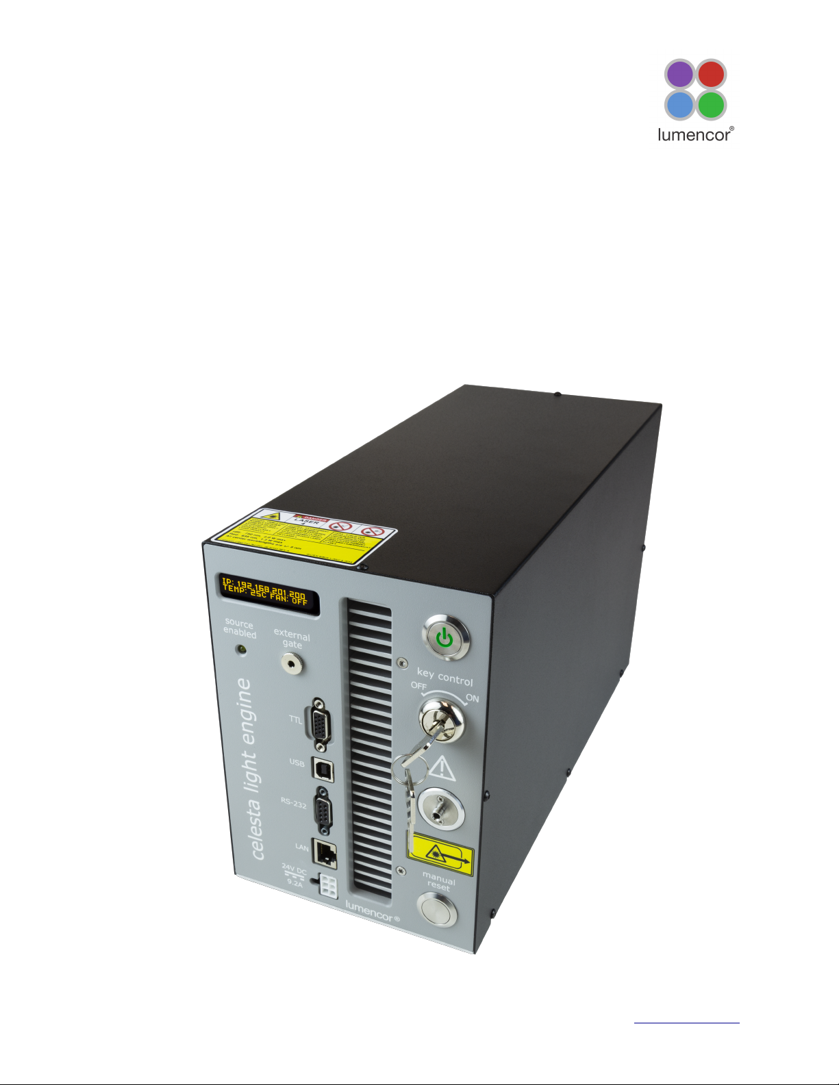
CELESTA Light Engine
®
Instruction Manual
Lumencor, Inc. Document Number 57-10015 www.lumencor.com
Page 2

Regulatory Models
Lumencor utilizes regulatory model names for all certified and CE marked products. The regulatory model
names are traceable to all regulatory documentation, third party reports and certifications.
“Regulatory Model: Celesta” is used as a representative model for all certified and CE marked Celesta
Products.
Emissions
This equipment has been tested and found to comply with the limits of EMC directive 2014/30/EU and FCC
part 15 (CISPR 11:+A1:2016). These limits are designed to provide reasonable protection against harmful
interference when the equipment is operated in a commercial environment. This equipment generates, uses,
and can radiate radio frequency energy and, if not installed and used in accordance with the instruction
manual, may cause harmful interference to radio communications.
Safety Certifications
TUV SUD America, CB Certification (IEC 61010-1:2010)
TUV SUD America, NRTLus Certification (UL 61010-1:2012-05)
TUV SUD America, cNRTL Certification (CAN/CSA-C22.2 No. 61010-1:2012)
TUV SUD America, EN Certification (EN 61010-1:2010)
Underwriters Laboratories (UL), CB Certification (IEC/EN 60825-1:2007 & 2014 Safety of laser products)
CE Marking
Low Voltage Directive (2014/35/EU)
EMC Directive (2014/30/EU)
RoHS Directive (2011/65/EU)
REACH Regulation (EC) No. (1907/2006/EC)
EU Declarations of Conformity can be found at http://lumencor.com/company/regulatory-compliance/
Lumencor, Inc.
14940 NW Greenbrier Parkway
Beaverton, OR 97006
T 503.213.4269
www.lumencor.com
Document Number 57-10015
Revision B
031919
CELESTA Light Engine® Instruction Manual
2
Page 3

Table of Contents
1. Introduction
2. Precautions and Warnings
3. Installation and Operating Instructions
4. Light Output Characteristics
5. Operational Specifications
6. Routine Maintenance and Troubleshooting
7. Customer Support
8. Warranty
CELESTA Light Engine® Instruction Manual
3
Page 4

1. Introduction!
The CELESTA light engine consists of individually addressable solid-state laser light sources with integrated
electronic control systems. The outputs of the laser light sources are refined by bandpass filters and
merged into a common optical train directed to the light output port on the front panel. The light output port
has a built-in adapter for connection to an SMA-terminated optical fiber. An onboard photodiode array
continuously monitors the light output and generates a reference signal that is applied to the constituent
sources in a feedback loop to maintain constant light output over time. The light sources within the
CELESTA light engine are controlled by software; via one of two serial interfaces, USB/RS-232 or TCP, to an
onboard microprocessor operating Lumencor firmware. The user can enable or disable each source
independently by serial commands as well as change the intensity of each source independently. The
CELESTA light engine can be controlled by third party microscopy data acquisition software or by a GUI
resident on the onboard microprocessor. Alternatively, the light sources may be turned on and off by TTL
inputs from a trigger device such as a camera or a real-time controller. Optimal internal operating
temperature is maintained by negative pressure air cooling with the air intake at the front of the light engine
and the exhaust fan at the rear.
CELESTA Light Engine® Instruction Manual
4
Page 5
2. Precautions and Warnings {Précautions et mises en garde}!
A few simple practices will ensure trouble-free operation for the life of the light engine.
Les quelques règles simples suivantes permettront d’assurer un fonctionnement fiable pendant toute la
durée de service de la source lumineuse.
Safety Instructions:
Please read and follow all safety instructions provided BEFORE using the CELESTA light engine. Failure to
comply with the safety instructions may result in fire, electrical shock, or personal injury and may damage or
impair protection provided by equipment. Please save all safety instructions.
Instructions de sécurité:
Veiller à lire et à respecter toutes les instructions de sécurité fournies AVANT d’utiliser le CELESTA light
engine afin d’écarter les risques d’incendie, de décharge électrique, de blessure corporelle et de possibles
dommages ou défaillance de la protection offerte par l’appareil. Conserver toutes les instructions de sécurité.
Safety Definitions {Définitions relatives à la sécurité}:
Warning: Statements identify conditions or practices that could result in personal injury.
Avertissement: déclarations qui identifient des situations ou des pratiques susceptibles
d’entraîner des blessures corporelles.
Caution: Statements identify conditions or practices that could result in damage to your equipment.
Attention: déclarations qui identifient des situations ou des pratiques susceptibles d’endommager le
matériel.
Safety Items {Mesures de sécurité}:
Warning: ONLY use the power supply provided by Lumencor. The Lumencor-supplied 24 VDC, 9.2 A
external power supply is required for use with the CELESTA light engine. The equipment is required to be
supplied by a properly approved/certified DC power source meeting the minimum electrical ratings of the
product. The DC power supply must have the AC power cord connected to a receptacle with a protective
safety (earth) ground terminal.
Avertissement: utiliser uniquement l'alimentation fournie par Lumencor. Le Lumencor fourni 24 VDC/
9.2 A alimentation externe est recommandé pour une utilisation avec le moteur de lumière CELESTA. Il est
impératif que l'alimentation DC a la sortie protection contre les surintensités, que la puissance de l’CELESTA
est pas fusionné. L'alimentation DC doit répondre aux exigences d'un circuit courant limité par la clause 9.4
de la IEC 61010-1 3rd ed. Branchez le cordon d'alimentation à une prise avec une sécurité de protection
(terre) borne de terre.
CELESTA Light Engine® Instruction Manual
5
Page 6
Warning: DO NOT look into the output of the light engine. The brightness of this light source is higher
than most commercial lighting fixtures and is intended to couple directly into a microscope or other
bioanalytjcal instrument.
Avertissement: NE PAS regarde directement la sortie de la source lumineuse. L’intensité lumineuse
de cette source est supérieure à celle de la majorité des appareils d’éclairage disponibles dans le commerce
et est conçue pour un raccordement direct à un microscope ou autre appareil de bioanalyse.
Warning: DO NOT turn on the light without!the output end of the light guide safely!directed!into an
enclosed optical path. "DO NOT point the light output directly onto any flammable or burn-susceptible
material." This includes all animal or vegetable tissues, plastics, fabrics, paper and liquids.!
Avertissement: NE PAS allumer la lumière sans l'extrémité de sortie du guide de lumière dirigée en
toute sécurité dans un chemin optique fermé. NE PAS pointer la sortie de lumière directement sur un
matériau susceptible d'être inflammable ou susceptible de brûler. Cela comprend tous les tissus, les
plastiques, les tissus, le papier et les liquides animaux ou végétaux.
Caution: Use of controls or adjustments or performance of procedures other than this specified herein
may result in hazardous radiation exposure.!
Attention: L'utilisation de commandes ou de réglages ou l'exécution de procédures autres que celles
spécifiées dans le présent document peuvent entraîner une exposition à des radiations dangereuses.
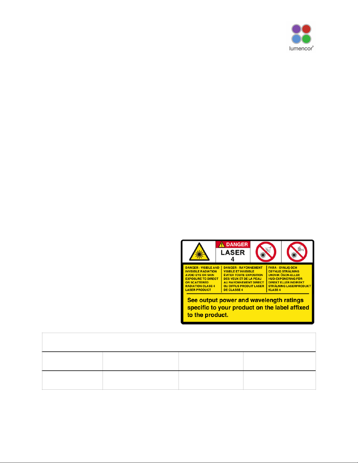
Class 4 Laser Warning
Warning: This product contains Class 4 laser
sources. Avoid eye and skin exposure to direct or
scattered visible and invisible laser radiation.
Avertissement: Ce produit contient des sources
laser de classe 4. Évitez l'exposition des yeux et de la
peau au rayonnement laser visible ou dispersé visible
et invisible.
Laser Sources
Color
Center Wavelength (nm)
Power
Beam Divergence
See label located on
product.
300 - 1150
See label located on
product.
NA: 0.39 = 23 degrees
CELESTA Light Engine® Instruction Manual
6
Page 7
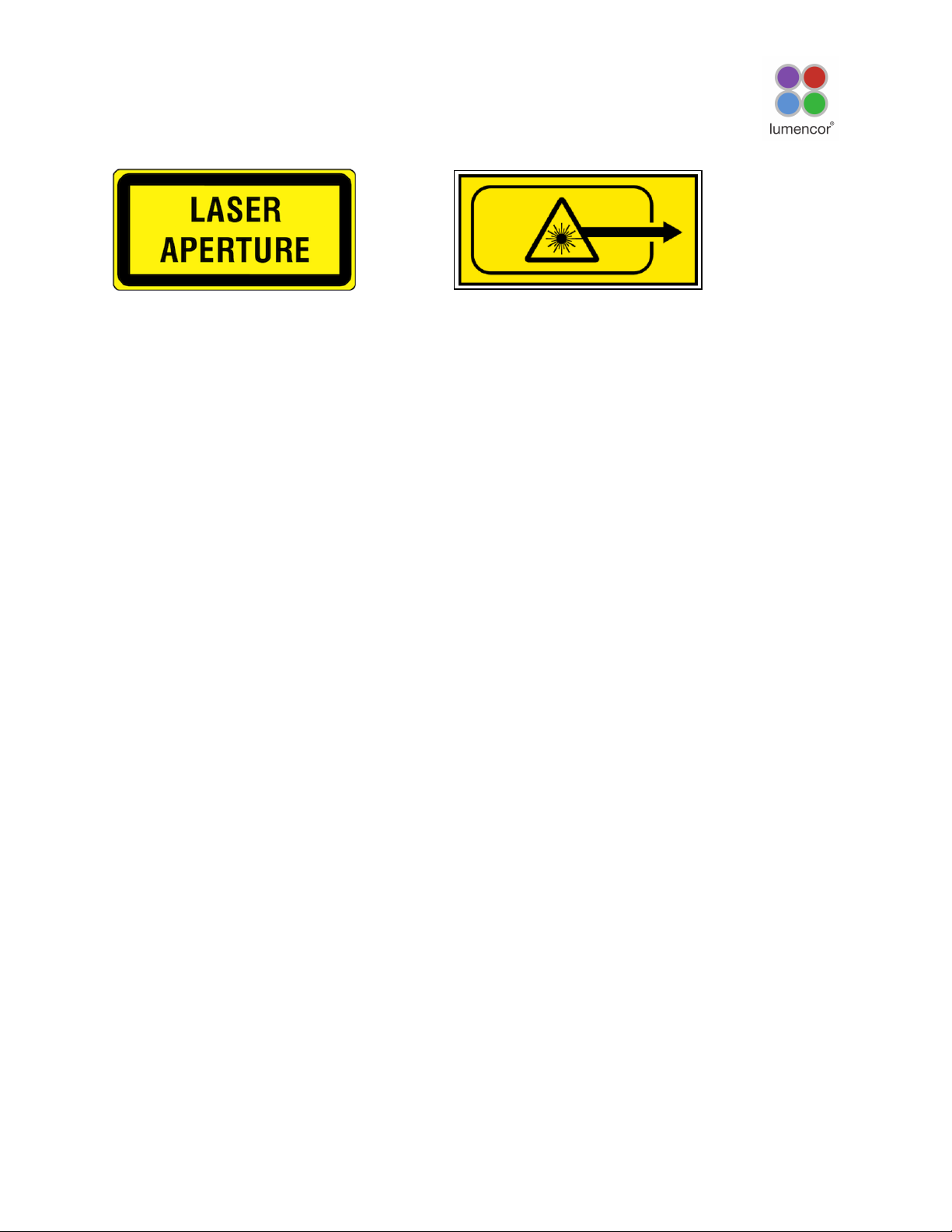
Laser Aperture Warning
Warning: Avoid exposure - laser radiation is emitted from this aperture. Do not turn on light engine without
first connecting a light guide to the output aperture. !The distal end of this light guide must be coupled into
an enclosed optical path prior to operation. Each operational control and laser aperture that can be
separated by 2m or more from a radiation warning device shall itself be provided with a radiation warning
device. Do not exceed 2m without providing a radiation warning device in accordance with EN
60825-1:2007 & 2014.
Avertissement: Évitez l'exposition - le rayonnement laser est émis à partir de cette ouverture. L'ouverture
de sortie est interverrouillée et un guide de lumière doit être connecté et couplé dans un chemin optique
inclus avant l'opération. Chaque commande opérationnelle et l'ouverture laser qui peuvent être séparées de
2 m ou plus à partir d'un dispositif d'avertissement de rayonnement doivent être munies d'un dispositif
d'avertissement de rayonnement. Ne dépassez pas 2m sans fournir un dispositif d'avertissement de
rayonnement conformément à la norme EN 60825-1:2007 & 2014.
Warning: DO NOT open the unit. There are no serviceable parts inside and opening the light engine
enclosure will void the manufacturer’s warranty.
Avertissement: NE PAS ouvrir l’appareil. Il ne contient aucune pièce réparable et l’ouverture de son
boîtier a pour effet d’annuler la garantie.
Caution: DO NOT set liquids on the light engine. Spilled liquids may damage your light engine.
Attention: NE PAS placer de liquide sur la source lumineuse. Les liquides renversés peuvent
endommager la source lumineuse.
Caution: DO NOT drop the light engine. It contains glass optical components that could be damaged or
misaligned by the shock produced by a drop onto a hard surface.
Attention: NE PAS laisser tomber la source lumineuse. Elle contient des composants optiques en verre
susceptibles d’être endommagés ou désalignés par le choc résultant d’une chute sur une surface dure.!
DISCLAIMER: Lumencor shall not be liable for injury to the user or damage to the product
resulting from the CELESTA light engine being used in a way for which it was not intended and in
complete disregard for all posted safety precautions and warnings.
AVIS DE NON-RESPONSABILITÉ: Lumencor décline toute responsabilité pour les blessures
corporelles ou les dommages au produit résultant d’une utilisation du CELESTA light engine autre
que celle prévue et du mépris total de toutes les mesures de sécurité et mises en garde affichées.
CELESTA Light Engine® Instruction Manual
7
OR
Page 8
3. Installation and Operating Instructions!
3.1 Contents!
The CELESTA light engine ships with the following list of standard components:
1. The CELESTA light engine, configured with 7 output channels
(colors) and an output adapter for connection to an SMA-
terminated optical fiber as documented on the certificate of
conformance (Figure 1).
2. A 24 V/9.2 A DC power supply (Lumencor part number
27-10019).
3. A region-specific AC power cord for the power supply (see
adjacent table).
4. RJ45 ethernet cable
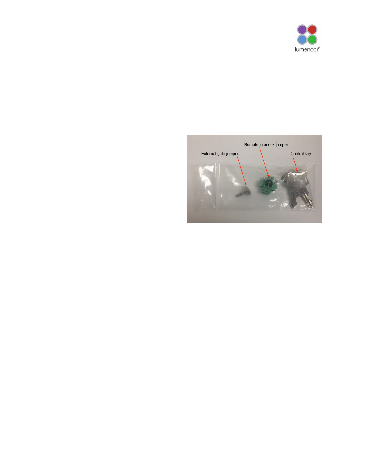
5. Control key, external gate jumper, and remote
interlock jumper (Figure 2)
6. Quickstart Guide instruction document
(85-10049)
The model name, unique 4- or 5- digit serial number and
certification markings of the light engine are carried on a
label affixed to the rear panel. Performance specifications
for individual light engines are listed on the certificate of
conformance included with the shipping documents emailed to the customer (Figure 1).
3.2 Installation!
When setting the CELESTA light engine up for use, place
the unit on a hard surface and avoid blocking or restricting
airflow at the air inlets (front panel; Figure 3) or exhaust
ports (rear panel) on the enclosure. Restricting the airflow
will cause the unit to operate at elevated temperatures
and will result in decreased product life and/or premature
failure. The CELESTA light engine must be operated in a
non-condensing environment (dew point <10ºC with
controlled ambient temperature <30º C). Thermal overload
protection is provided by the on-board computer in
conjunction with an on-board temperature sensor. If the
internal temperature registered by the sensor exceeds 50°C
OR the fan rotor is stopped, all light output channels
CELESTA Light Engine® Instruction Manual
8
AC Power Cords
Region
Part Number
North America
29-10002
Europe
29-10005
United Kingdom
29-10004
Israel
29-10008
Australia/New Zealand
29-10024
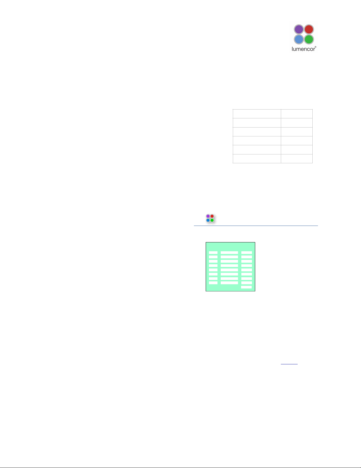
Figure 1. Specimen certificate of conformance (C of
C) for CELESTA light engine. The C of C identifies the
color channels installed in the light engine and the
bandpass filters associated with each channel. Full
(100%) power outputs measured at the terminus of
the optical fiber are recorded in the third column.
lumencor
DRAFT
14940 NW Greenbrier Parkway • Beaverton, OR 97006 • 503-213-4269 • www.lumencor.com
Performance Measurements For Lumencor Light Engine S/N
16112
Measurement Method
This product was measured using the custom output adapter installed on the light engine. The
output power was directed at a Coherent thermopile sensor head, model number ______, S/N
__________ attached to a Coherent ______________ Power Meter, S/N ___________. The
measurement system was calibrated on ____________. The meter scale was set to average mode
and the meter zeroed for each measurement. Measurements were taken at room temperature and
at initial turn-on.
Certificate of Conformance
n/a
512/30
555/28
635/22
475/28
747.5/11
440/20
406/20
Bandpass Filter
Color
Channel
Teal
n/a
Green
Red
Cyan
NIR
Blue
Violet
n/a
1000
1002
1019
1024
1013
1001
1005
Power (mW)
Mar 16, 2019
Tammy
Inspected By:
Celesta-NII-7F-A1
Lumencor Build Recipe:
Lumencor Part Number:
Customer Specification:
Document Part Number: 50-10027 rev C
Mar 26, 2018
0405I14R
0615I14R
7064
Total Power:
FieldMaxII-TO
PM30
Customer Part Number:
Fiber 1.5 - A
COC Output Adapter:
Burn-in Pattern
Note: If this light engine is re-sold, please
ensure that this certifcate is transferred to
the new owner.
n/a
Customer Deviation:
90-10512 Rev. A
SPECIMEN
Page 9
automatically turn OFF and are locked in this state until the internal temperature is below 50°C and/or the fan
restarts. The current reading of the on-board temperature sensor is displayed on the front panel status
display (Figure 3) and in the GUI (Figure 5).
3.3 Operation!
3.3.1 Controls and Interlocks!
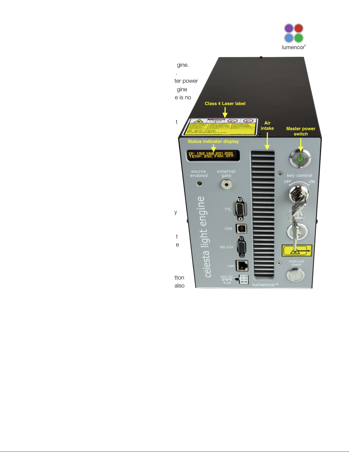
The Master Power Switch button on the front panel
(Figure 3) turns the electrical power to the unit on or off.
A green power indicator embedded in the button is lit
when the power supply is connected to the light engine
and the power button is in the on position. Initialization
of the onboard computer takes about 30 seconds after
the master power switch is turned on. When
initialization is complete, the status indicator display
(Figure 3) will activate.
The Key Control (Figure 3) must be in the on position
before the lasers can be turned on. The key must be
removed and stored in a secure location when the
product is not in use. ONLY trained individuals should
use and have access to the key. The Master Power
Switch button, Key control and Remote interlock
can be used to shut off laser output.
The Source Enabled indicator LED (below the status indicator display; Figure 3) provides a warning
indication that one or more laser sources are active and emitting invisible and/or visible radiation.
The Remote Interlock Connector (Figure 2): is provided to allow for connection of a remote interlock.
When this interlock is open it will shut off laser output. After the interlock has been opened, the Manual
Interlock Reset button will need to be pushed to resume laser output.
WARNING: Prior to turning the light output on, be sure the output end of the optical fiber is safely directed
into an enclosed optical path (e.g. a beam dump).
Note: In the event of ANY normal or abnormal interlock fault condition (including high ESD/EMP/EFT
conditions ~2kV) you MUST clear the latched fault condition by depressing the manual reset button.
3.3.2 Start Up!
1. Insert the optical fiber in the light output port (front , right-hand side) and lock it in place using the integral
threaded sleeve.[1].
2. Insert the external gate jumper (Figure 2) in the labeled socket on the front panel (Figure 3). Insert the
remote interlock jumper in the labeled socket in the lower left corner of the rear panel.
CELESTA Light Engine® Instruction Manual
9
Figure 2 . Control key, remote interlock jumper and
external gate jumper. These items are packed in a
plastic bag inside the shipping box. Their functions are
described in Section 3.3.1
Page 10
3. Insert the control key, turn it to the ON position.
4. Connect the isolated DC power supply to the light engine.
5. Connect the AC power cord to the DC power supply.
6. As soon the DC power supply is energized, the master power
button (top right) will automatically light up.! The light engine
automatically starts when the power is connected; there is no
need to push the master power button [2].
7. Wait 30–45 seconds for the initiation sequence
(onboard microprocessor boot-up) to complete.! Do not
press any buttons or insert any plugs during this time.
8. When the initiation sequence completes,
“LUMENCOR” will flash on front display panel and then
be replaced by a display showing the current light
engine IP address, the internal temperature and the fan
status.! At the same time, the fan will come on at HI for
about 2 seconds and then shut off automatically.
9. The light engine is now ready for use.
Notes
[1] Ensure that the distal end of the optical fiber is safely
directed into an enclosed optical path (e.g. microscope
epilluminator or a beam dump) before turning the light
output on. If the light engine is equipped with an output
adapter for an SMA-terminated optical fiber, connect the
fiber to the output adapter using the integral threaded
sleeve.
[2] For subsequent start ups, use the master power button
to start or shut down the light engine. Shut down can also
be accomplished using the “Shut Down” button in the Control
GUI (Figure 4).
3.3.3 Ethernet Connection and Control GUI!
The Web GUI provides a quick and easy way to control the light engine, providing the ability to turn each
source on/off, adjust the power of each source independently from off to full power (Figure 4). The GUI also
tracks the total on time for each laser light source and display output power readings from the onboard
photodiode array. A channel map stored on the onboard computer is used to the define the association of
control addresses with light sources. The channel map can be viewed by sending the command GET
CHMAP to the LAN port. To access the Web GUI on a Windows workstation, follow the protocol below:
1. Go to Start menu > Control Panel > Network & Internet and/ or Network & Sharing Center
2. Click Change Adapter Settings
3. Right-click on Local Area Connection
4. Click on Properties (in pop-up)
CELESTA Light Engine® Instruction Manual
10
Figure 3. CELESTA Light engine front panel
Page 11
5. Select Internet Protocol Version 4 (TCP/IPv4)
6. Click Properties button
7. Use the following IP addresses:
" IP Address: 192.168.201.201
" Subnet Mask: 255.255.255.0
" Default gate way and DNS Server are OK to leave blank
8. Connect the RJ45 cable (supplied with the light engine) between the LAN port on the light engine and an
ethernet port on the computer.
9. Type the Light Engine IP address (Figure) into any web browser address bar to access the resident Web
GUI. The factory default IP address is 192.168.201.200.
Control of the CELESTA light engine is implemented through a built in library of software commands. A
complete listing of the commands is provided in the Lumencor Light Engine Command Reference
(Document Number 57-10018). These commands can be delivered using using Transmission Control
Protocol (TCP) to the LAN input. The IP address of the light engine required for LAN communication is
shown on the front panel status display (Figure 3) or can be obtained using the GET IP command addressed
to the RS-232 or USB serial ports. The light engine software commands can also be delivered via the USB
or RS-232 serial ports (Figure 3) from various third-party data acquisition software packages.
CELESTA Light Engine® Instruction Manual
11
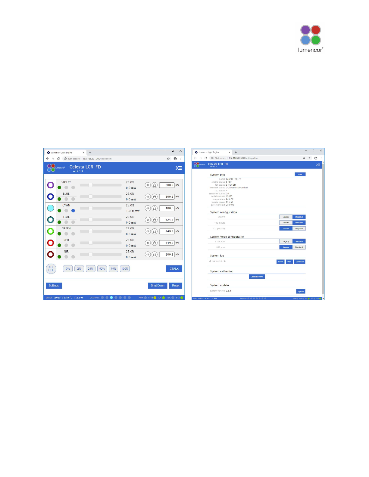
Figure 4. CELESTA GUI, Control Tab. The GUI is
accessed by typing the light engine IP address
(192.168.201.200 in this example) into a web browser.
The filled radio button indicates that Cyan channel output
is active.
Figure 5. CELESTA GUI, System Tab. The GUI is
accessed by typing the light engine IP address
(192.168.201.200 in this example) into a web browser.
Page 12
3.3.4 Control via Serial Ports!
CELESTA light engines have two serial ports, labeled USB and RS-232 (Figure 3), which can be set to
receive either LEGACY or STANDARD mode commands. Connection to the computer requires a USB-A-to-
USB B cable (29-10058) or USB-to-RS-232 cable (29-10011). LEGACY commands are limited to controlling
on/off switching and intensity adjustment of selected individual color channels. Only one of the two serial
ports can be set to LEGACY mode at one time. The STANDARD mode command set gives access to an
extensive panel of operating status reports and configuration settings in addition to the the basic control
functions of the LEGACY command set. A complete listing of STANDARD mode commands is provided in
Lumencor Light Engine Command Reference (Document number 57-10018). Note that LEGACY and
STANDARD mode communications use different serial protocols (9600,8,N,1 and 115200,8,N,1
respectively). Changes to the command mode setting for a serial port can be made via the Settings screen
of Web GUI (Figure 5). Changes are applied instantaneously and are retained between power cycles.
Select the command mode setting for the serial port that is compatible with the light engine device driver in
the control software. This selection is typically found under the “Devices” tab. The COM port address
assigned by the computer to the light engine USB serial port must be correctly registered in control software
at the same place.
3.3.5 Control From Light Engine Control Pod!
1. Connect the CELESTA to pod (p/n 83-10007) using USB A-to-USB B cable (p/n 29-10058)
2. Open the Web GUI control interface as described in Section 3.3.3.
3. Go to the SETTINGS page in the Web GUI. Make sure that the USB port configuration is set to LEGACY
mode and USB 5V is set to ENABLED.
4. The pod must be set in CELESTA control mode. The light engine control mode setting is shown in green
letters at the bottom of the pod display screen. If the pod is not in CELESTA control mode, change the
setting by holding down the MODE button on the pod until the light engine selection menu appears. Move
the cursor to “CELESTA” by turning the pod control knob. Press the MODE button again to select CELESTA
control mode and return to the main control screen.
5. Follow the instructions on Lumencor’s Light Engine Control Pod Operation sheet (p/n 54-10036). In brief,
press the COLOR button to select output light output channel, press the MODE button to toggle light output
on and off and turn the control knob to adjust intensity for the current light output channel selection.
3.3.6 TTL Control!
The TTL Interface provides users with a faster method of switching
color channel outputs on and off. Individual TTL inputs are
provided for each color channel, as shown in the adjacent table.
As a safeguard against unintended light output when the inputs
are initially connected, the light engine TTL port is disabled and
must be enabled by a serial command. To enable the TTL input,
click the Enabled button next to “TTL inputs” in the GUI under the
Settings tab (Figure 5) or send the standard mode command SET
TTLENABLE to the LAN port. Input TTL signals can be
conveniently addressed using an accessory BNC breakout cable
CELESTA Light Engine® Instruction Manual
12
TTL Connector Pin Definitions
OUTPUT
COLOR
Pin
#
OUTPUT
COLOR
Pin
#
RED1BLUE
12
GREEN
2
VIOLET
13
CYAN
3
nIR
14
TEAL
11
Gnd
6,7,8,10
V
ihigh
(min) = 2.0V, V
ihigh
(max) = 5.5V
V
ilow
(min) = 0.0V, V
ilow
(max) = 0.8V
Page 13
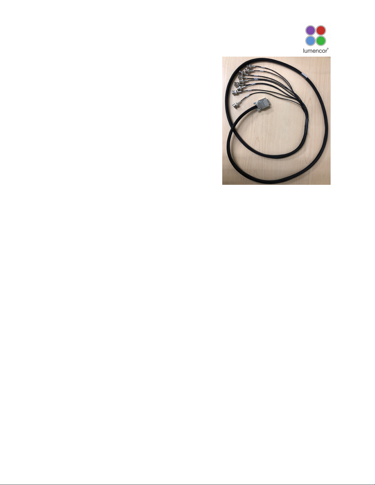
(Lumencor part no. 29-10156 or 29-10216; Figure 6) connected
to the front panel TTL port. The breakout cable also provides a
global shutter input (labeled “shutter”). TTL signals input to the
global shutter will synchronously toggle all currently enabled
source channels on and off.
4. Light Output Characteristics!
The solid state laser sources installed in the CELESTA light engine
and the bandpass filters associated with each are shown on the
Certificate of Conformance included with the shipping documents
e-mailed by Lumencor to the customer. The certificate of
conformance also shows full (100%) power outputs for each
source measured at the terminus of the optical fiber (Figure 1).
Not all sources may be turned on simultaneously. To prevent
exceeding the capacity of the DC power supply, power
consumption is tracked by the onboard computer. If a set limit
(see Governor, Figure 5) is exceeded, either by increasing
intensity settings for sources that are already on, or by turning on
additional sources, commands will be rejected. To clear the error condition, reduce intensities of sources
that are on or turn off additional sources.
Light source outputs are refined by bandpass filters. The specifications of these bandpass filters are
recorded on the certificate of conformance as CWL/FWHM where CWL =center wavelength and FWHM =
full width at half-maximum transmission, both measure in nanometers (nm). Bandpass filters are not userexchangeable and changes require return of the light engine to Lumencor’s factory for service (see Section
7). A new certificate of conformance will be provided as part of this service.
CELESTA Light Engine® Instruction Manual
13
Figure 6. BNC breakout cable (p/n
29-10156). The same cable configuration
with SMB connectors instead of BNC is
also available (29-10216)
Page 14

5. Operational Specifications!
The CELESTA light engine must be operated and stored within the environmental conditions specified in the
table below. Performance specifications for individual light engines are listed on the certificate of
conformance included with the shipping documents e-mailed to the customer (see example shown in Figure
1). It is important to retain the certificate of conformance for reference. In the event that the light engine is
sold, the certificate of conformance should be transferred to the new owner. Certificates of conformance are
also recorded in Lumencor’s database and copies can be requested by e-mail to
[email protected]. The request message must include the 4- or 5-digit serial number of the light
engine.
CELESTA Light Engine® Instruction Manual
14
Specification
Detail
Temperature
Operating
32 to 86° F (0 to 30° C)
Non-operating
-4 to 158° F (-20 to 70° C)
Humidity
Operating and non-operating
0 to 80% relative humidity, non-condensing#
Altitude
Operating
0 to 10,000 feet (3,048 meters)
Non-operating
0 to 45,000 feet (13,176 meters)
Dimensions
Size (W x L x H)
145 mm x 340 mm x 203 mm (5.7 in x 13.4 in x 8.0 in)
Weight
8.7 kg /19.1 lbs
Lifetime
Time for light engine output to decrease to 70% of the values
recorded on the original certificate of conformance

Power supply
24VDC / 9.2A
Warm-up Period
1 s
Protection
Thermal overload (Section 3.2). Power overdraw (Section 4)
Sound Level
Sound level at 1 meter < 65dB(A)
Control Interfaces
USB, RS-232, TCP, TTL
Warranty
18 months parts and labor
# The CELESTA light engine must be operated in a non-condensing environment (dew point <10ºC with
controlled ambient temperature <30º C). ¶The corresponding number of days/months/years may vary
considerably depending on the duty cycle implemented by the user and the prevailing environmental
conditions during operation.
Page 15

6. Routine Maintenance and Trouble Shooting
No routine maintenance is required. There are no user-replaceable components or sub-assemblies in the
CELESTA light engine. Opening the light engine enclosure will void the manufacturer’s warranty. In the event
that the light engine fails to perform in accordance with the specifications listed on the certificate of
conformance, please contact Lumencor Technical Support for assistance, as directed in Section 7.
7. Customer Support
For technical support of the CELESTA light engine, please contact Lumencor by phone at 503-213-4269 or
through e-, mail at [email protected]. Please be prepared to provide the 4- or 5-digit serial
number of the light engine. Any light engine returned to Lumencor for repairs or upgrades requires a preissued return material authorization (RMA) number. To obtain a RMA number, submit the online request form
at http://lumencor.com/support/lumencor-rma-request-form. It is the customer’s responsibility to properly
Troubleshooting Procedures
Problem
Check the following
No response to serial (USB or
RS-232) commands
Check that the LEGACY or STANDARD command mode selection
(GUI Settings; Figure 5) is compatible with the software driver.
No response to TTL trigger
commands
Check that TTL inputs are ENABLED (GUI Settings; Figure 5) and
that the TTL polarity setting is consistent with the trigger inputs.
Also check that all serial ON/OFF controls are in the OFF state.
No light output in response to
source ON command (serial or
TTL).
There are 4 interlocks that need to be closed, check all of these:!
1. Control key must be inserted in front panel and turned to “on”
position¶.!
2. Liquid light guide must be inserted in light output receptacle¶.!
3. Remote interlock jumper must be inserted in rear panel¶.!
4. External gate jumper must be inserted in front panel (Figure 3).
Unusually weak fluorescence
signals across all detection
channels
Weak fluorescence in all detection channels (DAPI, FITC, TRITC,
Cy5 etc) is likely to be due to poor light transmission by the liquid
light guide, the collimating adaptor or another distal component
of the microscope optical path and not to abnormally low light
output from the light engine.
Unusually weak fluorescence
signals in a single detection
channel (e.g. DAPI)
1. Check that the light engine power output reading in the Web
GUI (Figure 4) is normal.!
2. Check that the dichroic beamsplitter and emission bandpass
filter in the microscope are compatible with light engine
excitation filter specifications shown on the certificate of
conformance (Figure 1).
High, spatially uniform
fluorescence background
Check that the dichroic beamsplitter and emission bandpass filter
in the microscope are compatible with light engine excitation filter
specifications shown on the certificate of conformance (Figure 1).
¶ Open interlocks for these conditions will be indicated by a red status indicator in the lower right
corner of the GUI control screen (Figure 4)
CELESTA Light Engine® Instruction Manual
15
Page 16

package and safely ship products to Lumencor. Instructions for shipping will be provided in the e-mail giving
notification of the RMA number.
8. Warranty
The CELESTA light engine is backed by a 18 month warranty to end users. Warranty coverage starts on the
original date of shipment from Lumencor. Light Engines qualifying for warranty service must be verifiably
delivering performance that is substantially at variance with the levels documented in the certificate of
conformance. The light engine must also have been used and maintained under operating conditions
consistent with the specifications given in Section 5, and observing all the Precautions and Warnings notified
in Section 2. This warranty does not extend to light engines that have been subject to misuse, accident,
tampering or improper installation. Accessories including (but not limited to) optical fibers, collimators, cables
and control consoles are not covered by the warranties attached to light engines. Please fill out and submit
the online warranty registration form. This will facilitate provision of warranty service should it be required.
CELESTA Light Engine® Instruction Manual
16
 Loading...