

Page 1
DIGITAL PANEL METER
N20PLUS
USER’S MANUAL
1
Page 2

2
Page 3

Contents
1. APPLICATION AND METER DESIGN ........................................ 5
2. METER SET ................................................................................. 6
3. BASIC REQUIREMENTS, OPERATIONAL SAFETY ................. 6
4. INSTALLATION ........................................................................... 8
5. SERVICE.................................................................................... 10
6. MODBUS REGISTER MAP ....................................................... 18
7. ERROR CODES ........................................................................ 22
8. TECHNICAL DATA .................................................................... 23
9. EXECUTION CODES ................................................................ 26
3
Page 4

4
Page 5

1. APPLICATION AND METER DESIGN
The N20PLUS meter is a digital programmable panel instrument
destined for measurements of d.c. voltages or d.c. currents: unipolar or
bipolar, temperature through thermocouples (J, K) and Pt100 resistance
thermometers.
The N20PLUS meter has a built-in RS-485 interface and the MODBUS
RTU protocol provided on it, by means of which it is possible to congure
the meter or read measured values from it. The free eCon software
(available at www.lumel.com.pl) is destined for the conguration of the
N20PLUS meter. The meter should be connected to a PC computer via
the RS485 to USB converter, e.g. PD10.
Following parameters can be reprogrammed:
– display colour, individually in three intervals,
– thresholds of displayed overows
– display precision of the result (decimal point),
– highlight of the unit,
– automatic or manual compensation: temperature of ends in
measurements with thermocouples, or wire resistance in Pt100
measurements,
– averaging time of the measurement,
– recalculation of indications (individual characteristic),
– working modes for two outputs of OC type, to choose from 6 work modes;
– RS-485 transmission parameters;
– MODBUS bus settings.
The meter is equipped with two OC type outputs. The output
switching on is signaled by the highlight of the triangular alarm index
situated at the left display side, for the suitable alarm digit. The highlight
colour is always different from the colour of the displayed (measured)
value.
The meter has a galvanic separation between the supply, measuring
inputs and RS485 interface.
5
Page 6
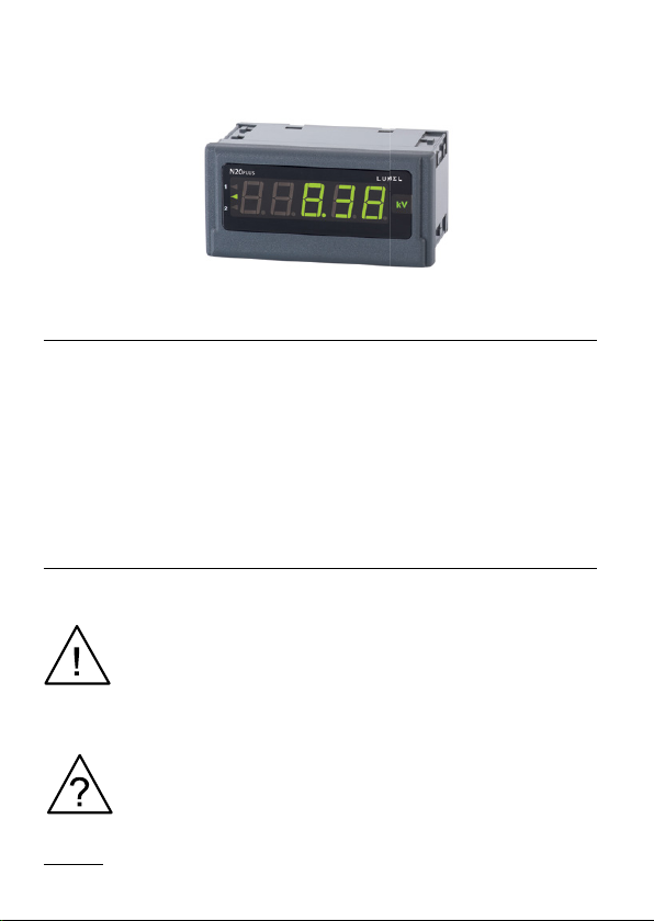
The protection grade of the meter from the front side is IP65. Dimensions
96 x 48 x 64 mm (including terminals). The meter housing is made of
self-extinguishing plastic.
Fig. 1. view of the N20PLUS meter
2. METER SET
The set is composed of:
- N20PLUS meter ........................................ 1 pc
- user’s manual ............................................ 1 pc
- clamps to x in the panel ......................... 4 pcs
3. BASIC REQUIREMENTS
AND OPERATIONAL SAFETY
Symbols located in this service manual mean:
WARNING!
Warning of potential, hazardous situations. Especially
important, one must acquaint with this before connecting
the meter. The non-observance of notices marked by these
symbols can occasion severe injuries of the personnel and
the damage of the meter.
CAUTION!
Designates a general useful note. If you observe it, handling
of the meter is made easier. One must take note of this,
when the meter is working inconsistently to the expectations.
Possible consequences if disregarded!
6
Page 7

In the safety service scope, the N20PLUS meter meets the
requirements of the EN 61010-1 standard.
Observations concerning the operational safety:
▪ All operations concerning transport, installation, and commissioning
as well as maintenance, must be carried out by qualied, skilled
personnel, and national regulations for the prevention of accidents
must be observed.
▪ Before switching the meter on, one must check the correctness of
connection to the network.
▪ The removal of the meter housing during the guarantee contract
period may cause its cancellation.
▪ The meter is destined to be installed and used in industrial
electromagnetic environment conditions.
▪ One must remember that in the building installation, a switch or a
circuit-breaker should be installed. This switch should be located
near the device, easy accessible by the operator, and suitably
marked.
7
Page 8
4. INSTALLATION
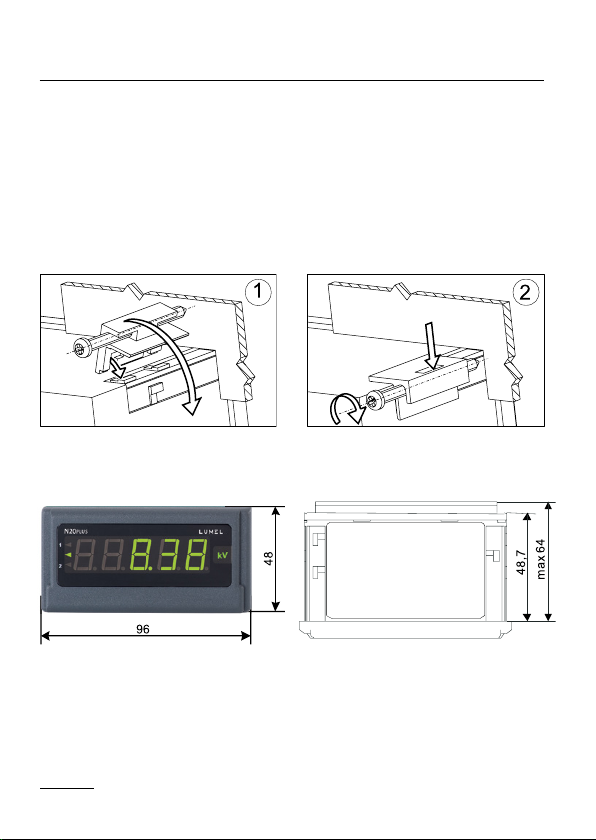
The meter has separable strips with screw terminals which enable the connection of external wires of 2.5 mm2. In the version for current measure-
ment, the plug enables permanent xing to the socket by means of screws.
One must prepare a hole of 92
thickness should not exceed 6 mm. The meter must be introduced from
the panel front with disconnected supply voltage. Before the insertion into
the panel, one must check the correct placement of the seal. After the
meter insertion into the hole, x the meter by means of the clamps ( g. 2.).
+0.6
Fig. 2. Meter xing.
45
+0.6
mm in the panel which the
Fig. 3. Meter overall dimensions
8
Page 9
4.1. Connection Diagrams
Rys. 3. Gabaryty miernika
4.1. Schematy podłączeń
~
Rys. 3. Gabaryty miernika
Rys. 4. Połączenia elektryczne miernika N20
PLUS
1 2 3
24V GND
24V
GNDA AL2 AL1 GND
RS485
B A zasilanie
~
PLUS
~
Rys. 3. Gabaryty miernika
Rys. 4. Połączenia elektryczne miernika N20
PLUS
1 2 3
Rezystor termometryczny w
układzie dwuprzewodowym z
kompensacją ręczną
1 2 3
Rezystor termometryczny w
układzie trójprzewodowym z
kompensacją automa tyczną
1 2 3
+ -
1 2 3 4 5 6 7 8 9 10 11 12 13 14 15 16
24V GND
24V
GNDA AL2 AL1 GND
RS485
B A zasilanie
Sygnały pomiarowe
~
PLUS
1 2 3
+ -
B A zasilanie
~
1 2 3 4 5 6 7 8 9 10 11 12 13 14 15 16
measuring signals
Sygnały pomiarowe
24V GND
GNDA AL2 AL1 GND
24V
B A zasilanie
RS485
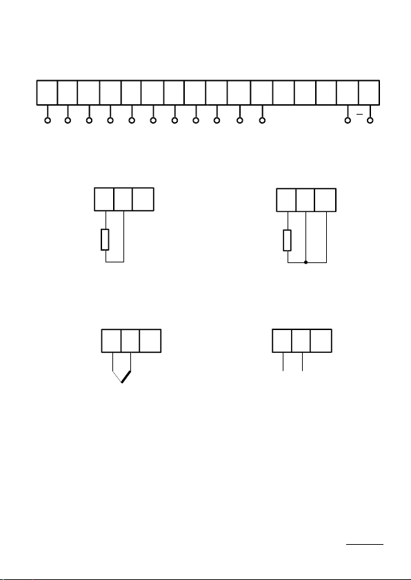
Fig. 4. Electrical connections of the N20PLUS meter
1 2 3
Resistance thermometer RTD
in a two-wire system with manual
compensation
1 2 3
+ -
in a three-wire system with automatic
Thermocouple J, K
Fig. 5. Connections of measurement inputs
The supply must be connected by a two-wire cable, of a suitable wire
diameter, ensuring its protection by means of an installation cut-out.
1 2 3
Resistance thermometer RTD
compensation
1 2 3
Current input
Voltage input
supply
9
Page 10
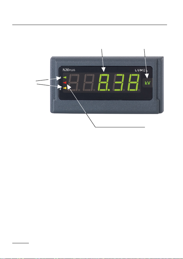
5. SERVICE
5.1. Display Description
Alarm
indexes
Fig. 6. Frontal panel
Measured
value
Indexes of actual value
displaying
Highlighted
unit
5.2. Messages after the Supply Connection
After connecting the supply, the meter displays the X, where
X the letter marking the execution of the meter: U – voltage measure-
ment, I – current measurement, r – measurement of Pt100 temperature,
t – measurement of the temperature by thermocouples, s – custom-made
execution. Next, the program version is displayed in the shape r x.xx –
where x.xx is the number of the actual program version or the number of
the custom-made execution.
Till the time to obtain the required number of correct measurements (acc.
to the table 1), the actual value from the measurement 1 is displayed,
signaled by the highlighted index of the actual value.
In case of an error occurrence or an over ow of the range value, a mes-
sage described in the section 7 will be displayed on the display.
Over ows of the measuring range are additionally signaled by the actual
value signal index.
10
Page 11
5.3. Meter Configuration
The free eCon software (available at www.lumel.com.pl) is destined for
the N20PLUS meter conguration. The meter should be connected to a
PC computer via the RS485 to USB converter, e.g. PD10, and then in the
E-Con program, select the transmission parameters according to those
set in the meter.
CAUTION! One must carry out the programming of meter parameters
when measuring circuits are switched off!
5.4. Parameters description
5.4.1. Display settings
After choosing the group: - Display settings, following elements are
possible to be congured:
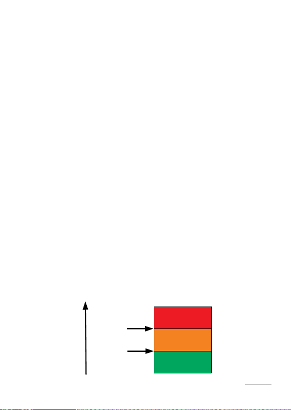
a) display colours of the measured value. The displayed range is divided
into three zones separated by KpL and KpH values (suitably the lower
threshold KpL and the upper threshold KpH of display colour change
– g.9). The colour of displayed numbers for each zone is selected
from three accessible colours: green, orange and red. KpL and KpH
values are set by the user and concern the displayed value (i.e. taking
also into consideration the individual characteristic). The manufacturer
value KpL is equal 100% of the rated value, however KpH is equal
105% of the rated value, e.g. for a 10 V meter execution they are
respectively: for KpL – 10 V and for KpH – 10.5 V.
Caution! After setting the individual characteristic, KpL and KpH
values are not automatically updated.
KpH
KpL
displayed value
Fig. 7. Display color conguration
11
Page 12

b) decimal point – measurement precision. We have 5 possible display
congurations at choice.
When choosing, one must follow the measurement precision, e.g.:
for the 10 V range – the measurement error is 0.02 V, so the choice
of precision with three places after the decimal point does not give
more precise measurements. When manufacturing, for executions
with voltage and current measurements, the precision 000.00 is set;
for executions with Pt100 temperature measurement – 0000.0; for
execution with the temperature measurement through thermocouples
– 00000.
c) unit highlight. The unit highlight can be enabled or disabled. When
manufacturing it is enabled.
5.4.1. Measurement settings
We can congure the measurement by changing the following elements:
a) Compensation (of terminal temperatures in the version with thermo-
couple measurement or resistance of wires for the version with Pt100
measurements). The switching of the automatic compensation off,
enables to give terminal temperature values or the wire resistance
used in calculations. As the resistance, one must give the sum of
both wires. At the beginning, the compensation is switched by the
manufacturer on.
b) Averaging time: till the time to obtain the required number of correct
measurements (according to the table 1), the actual value from 1 measurement is displayed. After measuring a denite number of measurements, the arithmetic mean of measured measurements is displayed.
Subsequent measurements are added on the principle of “rolling win-
dow”, i.e. the earliest measurement is discarded and the most recently
measured one is put in its place. The measurement of a value beyond
the measuring range causes the display of overow and the start to
count correct measurements from the beginning. The time is set on 1
s by the manufacturer.
12
Page 13
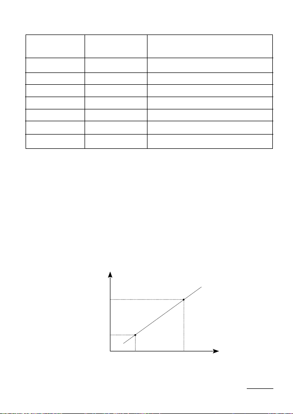
Table 1
wyświetlana
Averaging
time
0.5 s 2 every 0.5 s
1 s 7 every 0.5 s
3 s 20 every 0.5 s
5 s 33 every 0.5 s
10 s 67 every 0.5 s
15 s 100 every 0.5 s
20 s 133 every 0.5 s
Number of
averaging time
Updating of displayed values
c) thresholds of displayed overows: one can narrow limits beyond which
overows will be displayed, taking into consideration the individual
characteristic.When the measured value is beyond 0…110% of the
rated value (e.g. for the 10 V execution, it is the range -1…11 V),
the overow is displayed. In manufacturing conditions, the range
–19999…99999 is set.
d) switching the individual characteristic on. In manufacturing conditions
the characteristic is switched off.
The conguration of the individual characteristic consists in dening
the points of the linear characteristic used to convert the measured
value into the displayed value (Figure 8).
displayed
wartość
value
Y2
Y1
X1 X2 wartość mierzona
measured value
Fig. 8. Individual characteristic
13
Page 14
For example, to get values in kV, set points X1, X2, Y1, Y2 as follows:
y=A⋅x+B
Rys. 8. Charakterystyka indywidualna
X1 = 0, Y1 = 0, X2 = 10, Y2 = 1
y=A⋅x+B
A
=
Y
1−Y
2
X
1−X
2
B=Y1−
Y
1−Y
2
X
1−X
2
⋅X1
X1 X2 wartość mierzona
Y2
Y1
wartość
wyświetlana
X1 = 0, Y1 = 0, X2 = 10, Y2 = 1
This record means that for each measured value in the range
0 ... 10, the displayed value in the range 0 ... 1 will be calculated.
Having the points X1, Y1, X2, Y2, the coefcients A and B of the straight
line with the equation should be determined
according to the rule:
Coefcients A and B are individual characteristic parameters.
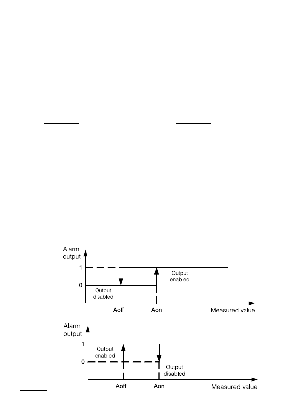
5.4.3. Setting of Alarm Parameters
Two alarms are available in the N20PLUS meter. Both alarms
are working independently and each of them has 6 working modes:
n-on, n-off, on, off, hon and hoff, which are presented on the g. 9. Alarm
thresholds Aoff and Aon are set in values of the measured quantity taking
into consideration the individual characteristic. In manufacturing conditions
both alarms are set on the n-on mode.
Additionally, for each alarm, you can set the parameter for the
delay of switching the state.
a) n-on
b) n-off
14
Page 15
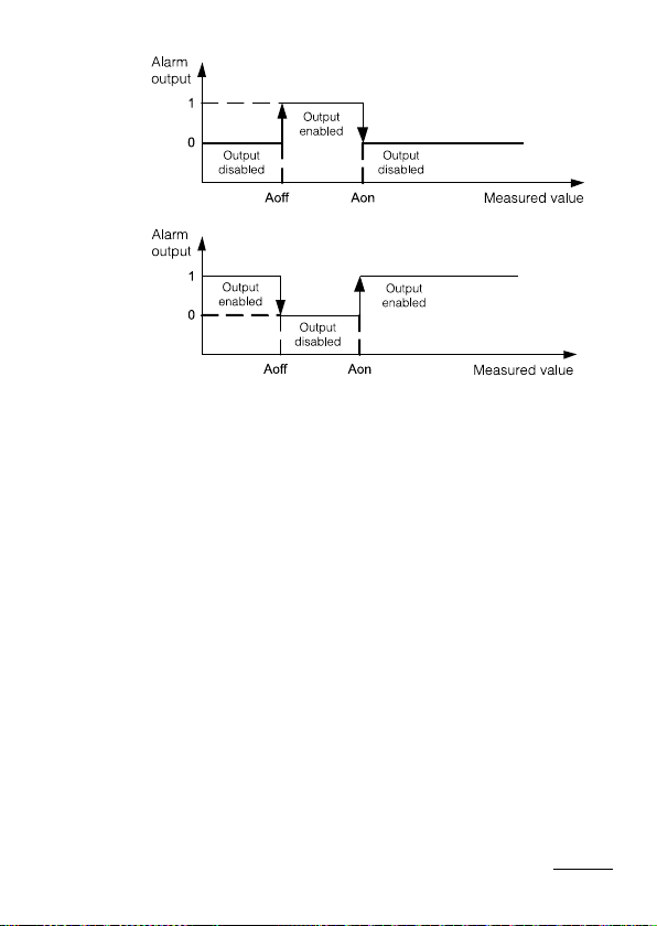
c) on
d) off
Fig. 9. Alarm types: a) n-on, b) n-off, c) on, d) off
Remaining types of the alarm: h-on – always switched on;
h-off – always switched off.
5.4.4. Communication Parameters
The N20PLUS meter is equipped with an isolated
RS-485 interface and communication takes place via the Modbus RTU
protocol. The following parameters are available to congure the correct
communication:
- address on the Modbus, can take values from the range 1 ... 247
- baud rate, are available: 4800, 9600, 19200, 38400, 57600,
115200 bps
- transmission mode, available for selection: 8N2, 8E1, 8O1, 8N1
15
Page 16
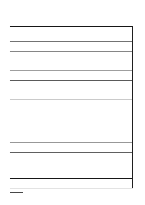
5.4. Manufacturer Parameters
Table 2
Parameter description Range/value Manufacturer value
Display colour of the measured
upper value
Display colour of the measured
middle value
Display colour of the measured
lower value
Upper threshold - KpH -19999…99999
Lower threshold - KpL -19999…99999
Decimal point
Highlight of the measured unit switched off, switched on switched on
Automatic compensation of
the terminal temperature/wire
resistance
Manual compensation value:
terminal temperature
wire resistance
in other cases
Averaging time
Upper overow of the
measurement
Lower overow of the
measurement
Individual characteristic switched off, switched on switched off
Parameter a of the individual
characteristic
Parameter b of the individual
characteristic
red, green, orange red
red, green, orange orange
red, green, orange green
105% of rated value Un,
In or 200°C
100% of rated value Un,
In, or 100°C
00000, 0000.0, 000.00,
00.000, 0.0000,
switched off, switched on
-20…60°C
0…20 Ω
0
0.5 s, 1 s, 3 s; 5 s, 10 s,
15 s, 20 s,
-19999…99999 99999
-19999…99999 -19999
-19999…99999 1
-19999…99999 0
000.00 for U,I, 00000 for
thermocouples J and K
0000.0 for Pt100
switched on (for Pt100,
thermocouples J and K),
switched off for other
executions
40°C
0 Ω
0
1 s
16
Page 17
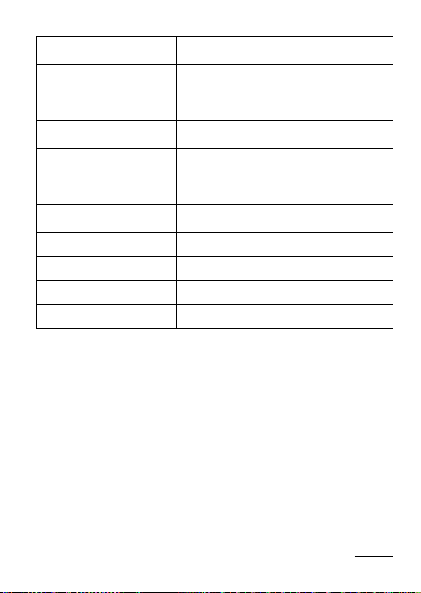
Action mode of the alarm output 1
Upper value of the alarm 1
switching - Aon
Lower value of the alarm 1
switching - Aoff
Delay of the alarm 1 switching
time
Action mode of the alarm output 2
Upper value of the alarm 2
switching - Aon
Lower value of the alarm 2
switching - Aoff
Delay of the alarm 2 switching
time
Modbus device address 1...247 1
Baud rate
Transmission mode 8N2, 8E1, 8O1, 8N1 8N2
n-on, n-off, on, off, h-on,
h-off
-19999…99999
-19999…99999
0…120 0 second
n-on, n-off, on, off, h-on,
h-off
-19999…99999
-19999…99999
0…120
4800, 9600, 19200,
38400, 57600, 115200
105% of rated value Un,
100% of rated value Un,
105% of rated value Un,
100% of rated value Un,
In, or 100°C
0 second
9600
n-on
In, or 200°C
In, or 100°C
n-on
In, or 200°C
17
Page 18
6. MAP OF MODBUS REGISTERS
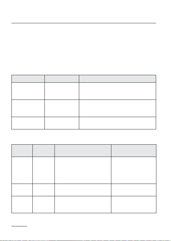
In the N20PLUS meter, the data is placed in 16 and 32 bit registers.
Parameters and measured values of the meter are placed in the address
space in a way depending on the variable value type. In 16-bit registers,
bits are numbered from the youngest to the oldest (b0-b15). 32-bit regis-
ters contain oat numbers. The list of available registers is presented in
Table 3. The ranges of changes in the value of registers are presented
in tables 4 and 5.
Address range Value type Description
4000 - 4023 Integer (16 bits) Configuration of meter operation
7600 - 7609 Float (32 bits) Configuration of meter operation
7610 - 7611 Float (32 bits) Measured values (oating point). Value
Address
4000 RW Decimal point of the display
4001 RW Unit backlight 0 – off
4002 RW Display color for values below
Register
type
(display precision)
the KpL threshold (Fig. 7) set
in register 7603
parameters (fixed-point parameters).
Value placed in one 16-bit register.
parameters (oating point parameters).
Value placed in one 32-bit register.
placed in one 32-bit register.
Description Changes range
0 - 00000
1 - 0000.0
2 - 000.00
3 - 00.000
4 - 0.0000
1 – on
0 - orange
1 - red
2 - green
Table 3
Table 4
18
Page 19

4003 RW Display color for values
between KpL and KpH
thresholds (Fig. 7) set in
registers 7602 and 7603
4004 RW Display color for values above
the KpH threshold (Fig. 7) set
in register 7602
4005 RW Alarm type 1 (section 5.4.3) 0 – n-on
4006 RW Alarm 1 delay time 0...120
4007 RW Alarm type 2 (section 5.4.3) 0 – n-on
4008 RW Alarm 2 delay time 0...120
4009 RW Switching on of individual
characteristics.Characteristics
parameters placed in registers
7600 and 7601
4010 RW Averaging time (section 5.4.2 b) 0 – 0.5 s
4011 RW Temperature compensation
mode of terminal / wire
resistance
0 - orange
1 - red
2 - green
0 - orange
1 - red
2 - green
1 – n-off
2 – on
3 – off
4 – hon
5 – hoff
1 – n-off
2 – on
3 – off
4 – hon
5 – hoff
0 – individual char. off
1 – individual char. on
1 – 1 s
2 – 3 s
3 – 5 s
4 – 10 s
5 – 15 s
6 – 20 s
0 - manual, value in
reg. 7610
1 - automatic
19
Page 20
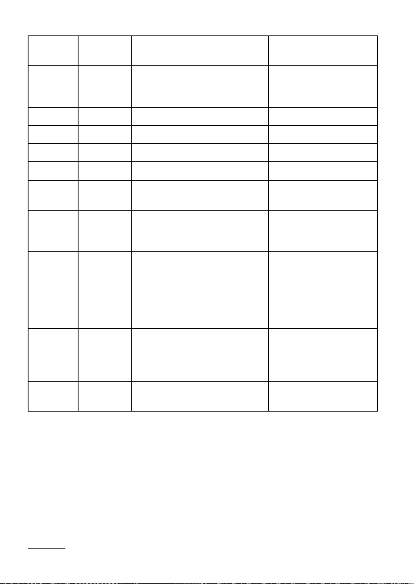
4012 R Restoring factory parameters
of the meter
4013 R The meter status, read only
value, represents the current
operating status.
4014 RW reserved Not applicable
4015 R reserved Not applicable
4016 R reserved Not applicable
4017 R reserved Not applicable
4018 R Meter’s serial number (older
16 bits of 32-bit value)
4019 R Meter’s serial number
(younger 16 bits of 32-bit
value)
4021 RW Baud rate (change requires
acceptance by writing to
registry 4023)
4022 RW Transmission mode (change
requires acceptance by writing
to registry 4023)
4023 RW Application of transmission
parameters.
0 - do not do anything
1 - restore parameters
Not applicable
Not applicable
0 – 4800
1 – 9600
2 – 19200
3 – 38400
4 – 57600
5 – 115200
0 – 8N2
1 – 8E1
2 – 8O1
3 - 8N1
0 - do not do anything
1 - apply changes
20
Page 21
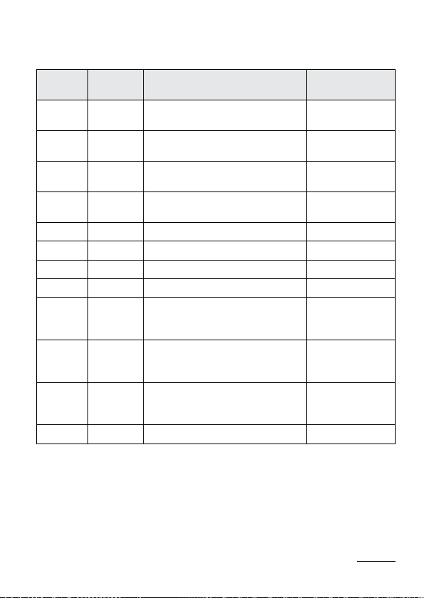
Table 5
Address
7600 RW Parameter A of the individual
7601 RW Parameter B of the individual
7602 RW Value of exceeding the upper
7603 RW Value of exceeding the lower
7604 RW Upper alarm trigger threshold 1 -19999…99999
7605 RW Alarm trigger lower threshold 1 -19999…99999
7606 RW Upper alarm trigger threshold 2 -19999…99999
7607 RW Alarm trigger lower threshold 2 -19999…99999
7608 RW The upper threshold for the color
7609 RW The lower threshold for the color
7610 R Value for manual temperature
7611 R Measured value of the input signal Not applicable
Register
type
Description Changes range
-19999…99999
characteristic (section 5.4.2.d)
-19999…99999
characteristic (section 5.4.2.d)
-19999…99999
display value
-19999…99999
display value
-19999…99999
change of the KpH display (section
5.4.1.a)
-19999…99999
change of the KpL display (section
5.4.1.a)
-20..60
compensation of terminals / wire
resistance
21
Page 22

7. ERROR CODES
After connecting the meter to the network, messages about errors may
appear. Causes of errors are presented below:
Overow of the upper value of the programmed indica-
tion range. In the option with Pt100, it also signals the
incorrect connection of the wire to the terminal 4.
Overow of the lower value of the programmed indica-
tion range.
ErrCA Loss of meter calibration values – In such a case, one
ErrEE Incorrect values in meter conguration data. One must
must contact an authorized service workshop.
set up again meter parameters by means of the eCon
software.
22
Page 23

7. TECHNICAL DATA
Measuring ranges:
INPUTS:
Measuring ranges of Un voltage:
-165 mV...-150 mV...150 mV...165 mV
-1 mV...0 mV...150 mV...165 mV
-82,5 mV...-75 mV...75 mV...82.5 mV input resistance > 1 M
-1 mV...0 mV...75 mV...82.5 mV
-1 V... 0 V...10 V...11 V
-11 V... -10 V...10 V...11 V
Measuring ranges of In current:
-1...0... 20...22 mA input resistance 10 1%
3.6...4... 20...22 mA input resistance 10 1%
-22...-20... 20...22 mA input resistance 5 1%
Temperature measurement
through Pt100: - 50... 400°C
current owing through
the sensor < 300 mA
Resistance of wires connecting
the resistance thermometer to
the meter: £ 10 (of one wire)
Temperature measurement
through thermocouple J: - 50...1200°C
Temperature measurement
through thermocouple K: - 50...1370°C
Preheating time: 30 min.
Intrinsic error
(at manufacturer settings): (0.2% of the range 1 digit)
23
Page 24

Additional errors in rated
operating conditions:
- compensation of reference
junction temperature changes: 0.2% of the range
- compensation of wire
resistance changes: 0.2% of the range
- from ambient temperature
changes: (0.1% of the range/10 K)
Averaging time: £ 0.5s (1s by default)
Alarm outputs: outputs of OC type (30 V, 20 mA),
passive outputs acc. to EN 62053-31
Output to supply external
transducers: 24 V 5%, 30 mA
Serial interface: RS-485, address 1..247
mode: 8N2, 8E1, 8O1, 8N1
baude rate: 4.8, 9.6, 19.2, 38.4, 57.6, 115.2 kbit/s
transmission protocol: modbus RTU
time to start the answer: 100 ms
Rated operating conditions:
- supply voltage: 85...253 V a.c. (45...65 Hz) or d.c.
20...40 V a.c. (45...65 Hz) or d.c.
- ambient temperature: - 10...23...55°C
- storage temperature: - 25... + 85°C
- relative air humidity: < 95% (inadmissible condensation
of water vapour)
- working position: any
Sustained overload capacity
(measurement of voltage, current): 10%
24
Page 25

Short duration overload
capacity (3 s):
- sensor inputs 30 V
- voltage input 10 Un
- current input 10 In
Readout eld 5-digit three-colour LED displays:
- digit height: 14 mm,
- colours: green, orange, red
- indication range: -19999...99999
Ensured protection grade
from frontal side IP 65 acc. EN 60529
Overall dimensions 96 48 64 mm (with terminals)
+0.6
Cut-out dimensions in panel 92
45
+0.6
mm
Weight < 0.25 kg
Power consumption < 6 VA
Galvanic isolation between:
– supply - measuring input 3.2 kV d.c.
Electromagnetic compatibility:
– noise immunity acc. to EN 61000-6-2
– noise emission acc. to EN 61000-6-4
Safety requirements acc. to EN 61010-1 standard:
– isolation between circuits basic
– installation category III
– pollution degree 2
– maximal phase-to-earth
working voltage:
– for supply circuit 300 V (at supply 85...253 V),
– for measuring input 50 V,
– for input destined for programming 50 V.
– altitude above sea level: < 2000 m
25
Page 26

9. ORDERING CODES
Input:
Pt100: -50...400 °C 1
Thermocouple J: -50...1200 °C 2
Thermocouple K: -50...1370 °C 3
0...20 mA 4
4...20 mA 5
20 mA
0...75 mV 7
0...10 V 8
10 V
0...150 mV A
75 V
150 V
Supply:
85...253 V a.c./d.c. 1
20..40 V a.c./ d.c. 2
Unit:
unit code number acc. to table 7 XX
Version:
standard 00
custom-made XX
Language:
Polish P
English E
Acceptance test:
without additional quality requirements 0
with an extra quality inspection certicate 1
with an extra calibration certicate 2
acc.to customer’s request* X
N20PLUS X X XX XX X X
6
9
B
C
Table 6
* only after agreeing with the manufacturer
26
Page 27
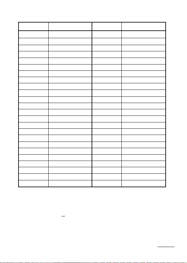
Code of the highlighted unit Table 7
Code Unit Code Unit
00 without unit
01 V
02 A
03 mV
04 kV
05 MA
06 mA
07 kA
08 MA
09 °C
10 °F
11 K
12 Hz
13 kHz
14 Ah
15 kAh
16 m/s
17 mm
18 mm
19 cm
20 m
21 km
22 l
23 l/s
1)
- After agreeing with the manufacturer
24 l/h
25 ms
26 s
27 h
28 N
29 kN
30 Pa
31 hPa
32 kPa
33 MPa
34 bar
35 rad
36
37 k
38 %
39 °
40 rev.
41 rps
42 rpm
43 rph
44 m/h
45 km/h
46 imp
XX on order
1)
ORDERING EXAMPLE:
The Code N20PLUS 910100E0 - means: N20ZPLUS meter with voltage
input on 10 V, supply 85... 253 V a.c., standard version, user’s manual
in English, without aditional quality requirements. Unit„V”
27
Page 28

28
LUMEL S.A.
ul. Sulechowska 1, 65-022 Zielona Góra, POLAND
tel.: +48 68 45 75 100, fax +48 68 45 75 508
www.lumel.com.pl
Export department:
tel.: (+48 68) 45 75 139, 45 75 233, 45 75 321, 45 75 386
fax.: (+48 68) 32 54 091
e-mail: [email protected]
N20PLUS-09
 Loading...