

Page 1
1
LARGE SIZE DIGITAL
DISPLAYS
DL11, DL12 and DL13 types
USER’S MANUAL
Page 2

2
Page 3

3
CONTENTS:
1. APPLICATION .............................................................................................................................2
2. DISPLAY SET ..............................................................................................................................2
3. BASIC REQUIREMENTS, OPERATIONAL SAFETY .................................................................2
4. DESIGN DESCRIPTION AND INSTALLATION ..........................................................................2
5. ELECTRICAL CONNECTIONS ..................................................................................................4
6. CONFIGURATION OF THE DL DISPLAY ..................................................................................5
6.1 Configuration of the connection .............................................................................................
6
6.2 Changing transmission parameters .......................................................................................
6
6.3 Display configuration .............................................................................................................
6
6.4 Setting time/date ....................................................................................................................
7
6.5 Setting the luminosity brightness ...........................................................................................
8
6.6 Display status ........................................................................................................................
8
6.7 configuration of the display for data read-out from additional devices ..................................
8
7. INTERFACE .................................................................................................................................9
7.1 Registers: 4000...4031 ..........................................................................................................
9
7.2 Registers: 4300...4349 ........................................................................................................
10
7.3 Registers: 7500...7653 ........................................................................................................
14
8. TECHNICAL DATA ....................................................................................................................16
9. ORDER CODES .........................................................................................................................17
10. BEFORE A DAMAGE WILL BE DECLARED ............................................................................18
11. MAINTENANCE AND SERVICE ................................................................................................19
LARGE SIZE DIGITAL DISPLAYS
DL11, DL12 and DL13 types
January 2007
Page 4

4
Page 5

5
1. APPLICATION
Large-size digital displays of DL type are destined to display measured values o set values through the
communication interface. Taking in consideration the application of 7-segment LED displays they are
destined to be installed inside buildings.
The 100 mm digit height ensures a good readout from the distance of 40 m.
They find application in office accommodations , production workshops, in production management
rooms as information about production parameters, state of machines or devices.
The displayed value is transmitted from external devices working in MODBUS standard. The display
is working as the network „master”. The basic display version includes three digits and the unit, in two
rows or three rows.
It is possible to make the display in the configuration required by the customer.
2. DISPLAY SET
The display set is composed of:
- DL11, DL12 or DL13 display 1 pc
- Suspension holder 2 pcs
- Diskette with software 1 pc
- User’s manual 1 pc
- Guarantee card 1 pc
When unpacking the display, please check whether the type and execution code on the data plate
correspond to the order.
3. BASIC REQUIREMENTS, OPERATIONAL SAFETY
Symbols located in this service manual mean:
WARNING!
Warning of potential, hazardous situations.
Especially important. One must acquaint with this before connecting the digital display.
The non-observance of notices marked by these symbols can occasion severe injuries of
the personnel and the damage of the device.
CAUTION!
Designates a general useful note. If you observe it, handling of the device is made easier.
One must take note of this, when the device is working inconsistently to the expectations.
Possible consequences if disregarded!
In the security scope the digital display meets the requirements of the EEC
Low-Voltage Directive (EN 61010 -1 issued by CENELEC ).
Remarks concerning the operator safety:
1. G
eneral
n The DL large displays are destined to be mounted in accordance with customer’s requirements.
n Non-authorized removal of the required housing, inappropriate use, incorrect installation or
operation creates the risk of injury to personnel or damage to equipment. For more detailed
information please study the User’s Manual.
n All operations concerning transport, installation, and commissioning as well as maintenance must
be carried out by qualified, skilled personnel and national regulations for the prevention of
accidents must be observed.
n According to this basic safety information, qualified, skilled personnel are persons who are
familiar with the installation, assembly, commissioning, and operation of the product and who
have qualifications necessary for their occupation.
Page 6

6
2. TransporT, sToraGe
n Please observe the notes on transport, storage and appropriate handling.
n Observe the climatic conditions given in Technical Data.
3. I
nsTallaTIon
n The DL digital display must be installed according to the regulation and instructions given in this
User’s Manual.
n Ensure proper handling and avoid mechanical stress.
n Do not bend any components and do not change any insulation distances.
n Do not touch any electronic components and contacts.
n Devices may contain electrostatically sensitive components, which can easily be damaged by
inappropriate handling.
Do not damage or destroy any electrical components since this might endanger your health!
4. e
lecTrIcal connecTIon
n Before switching the device on, one must check the correctness of connection to the network.
n In case of the protection terminal connection with a separate lead one must remember to connect
it before the connection of the device to the mains.
n When working on live devices, the applicable national regulations for the prevention of accidents
must be observed.
n The electrical installation must be carried out according to the appropriate regulations (cable
cross-sections, fuses, PE connection). Additional information can be obtained from the user’s
guide.
n The documentation contains information about installation in compliance with EMC (shielding,
grounding, filters and cables). These notes must be observed for all CE-marked products.
n The manufacturer of the digital display or installed devices is responsible for the compliance with
the required limit values demanded by the EMC legislation.
n Do not connect the digital display to the mains through an autotransformer.
n The RS-485 socket serves only to connect devices working with the MODBUS protocol.
5. o
peraTIon
n Measuring systems including DL digital displays, must be equipped with protection devices
according to the corresponding standard and regulations for prevention of accidents.
n After the display has been disconnected from the supply voltage, live components and power
connections must not be touched immediately because capacitors can be charged.
n The housing must be closed during operation.
n The protection degree ensured by the housing is defined as IP40 and IP10 from the connection
side.
6. M
aInTenance and servIcInG
n Please observe the manufacturer’s documentation.
n Read all product-specific safety and application notes in this User’s Manual.
n Before taking the device housing out, one must turn the supply off.
n The removal of the device housing during the guarantee contract period may cause its
cancellation.
4. DESIGN DESCRIPTION AND INSTALLATION
The display housing is made of profiles and aluminium sheets, painted in black colour.
The frontal surface is made of polycarbonate as an anti-reflexive glass.
The protection degree ensured by the housing is defined as IP40.
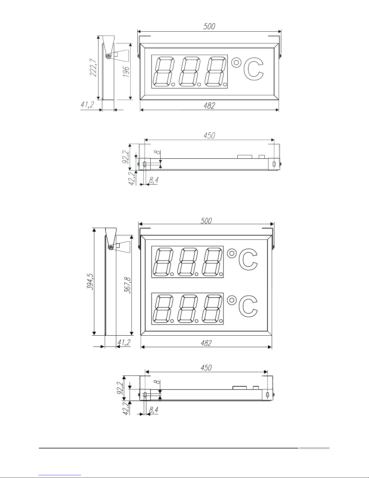
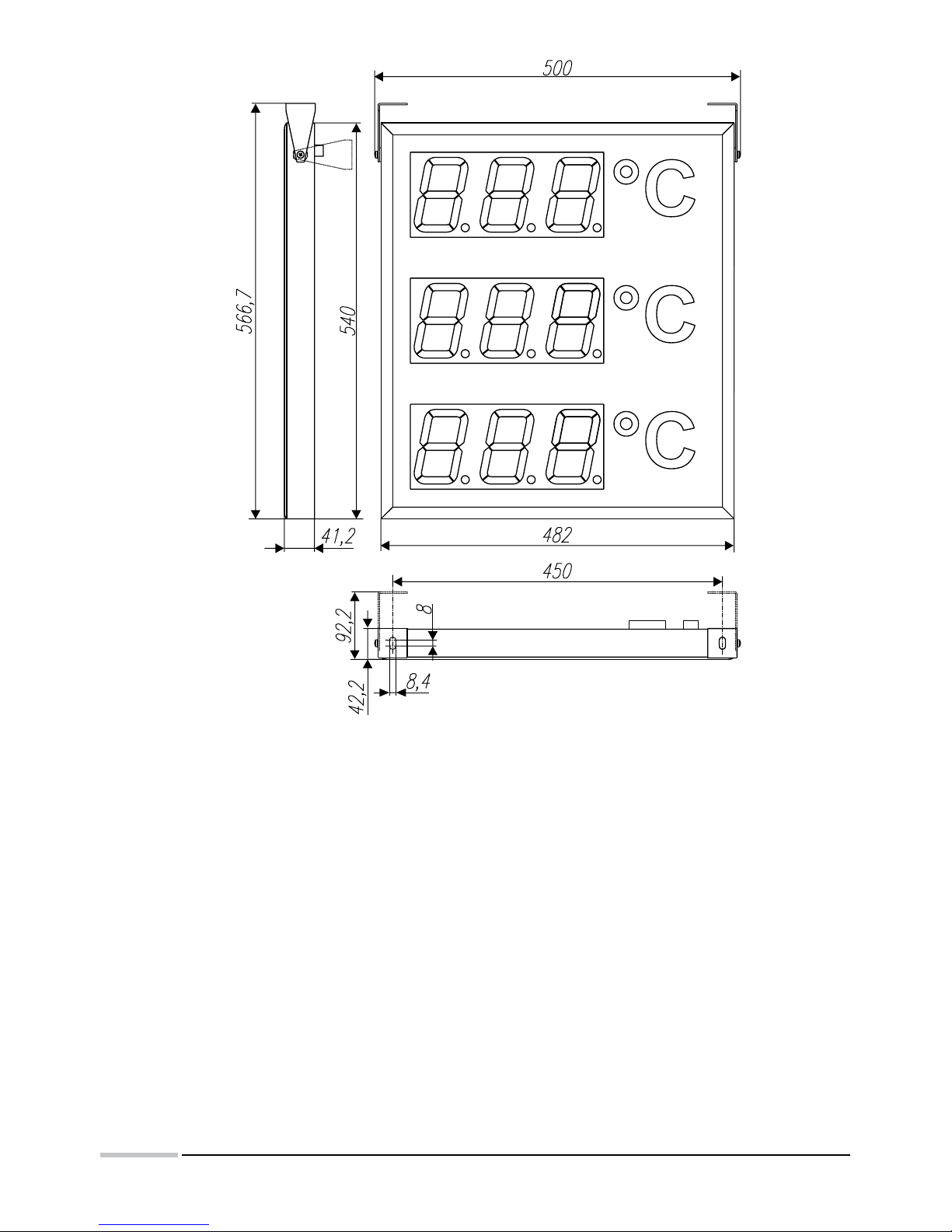
The view and overall dimensions of DL11, DL12 and DL13 displays are presented on fig. 1, 2 and 3.
The design enables to fix the display on a wall.
Page 7
7
Fig.1 overall dimensions of the DL11 display.
Fig.2 overall dimensions of the DL12 display.
Page 8
8
Fig.3 overall dimensions of the DL13 display
5. ELECTRICAL CONNECTIONS
Caution: the installation and display connections should be carried out by a qualified
personnel.
The connection of supplying wires and interface should be carried out only in accordance with the
user’s manual. In case of inconsistent connections with the assigned connectors the display can be
damaged. For the connection of control signals one must apply a wire coil in a shield.
In case of an environment with a low level of noise it is admissible to apply a wire coil non-shielded.
Caution: in case of a sudden change of the ambient temperature, dew may occur and it is forbidden
to connect the display to the supply. It is recommended before mounting the display which changes
suddenly its temperature, to wait at least 60 minutes before the first start.
Page 9
9
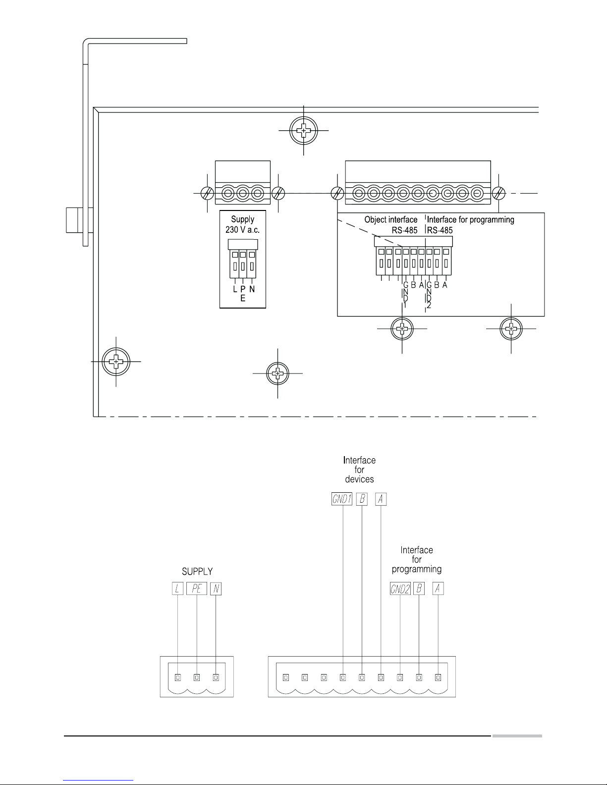
Fig.4. Markings of connectors for DL11, DL12, DL13:
Page 10
10
Before carrying out changes of the given parameter, it
s recommended to carry out the read-out of the current
configuration and modify the chosen parameter.
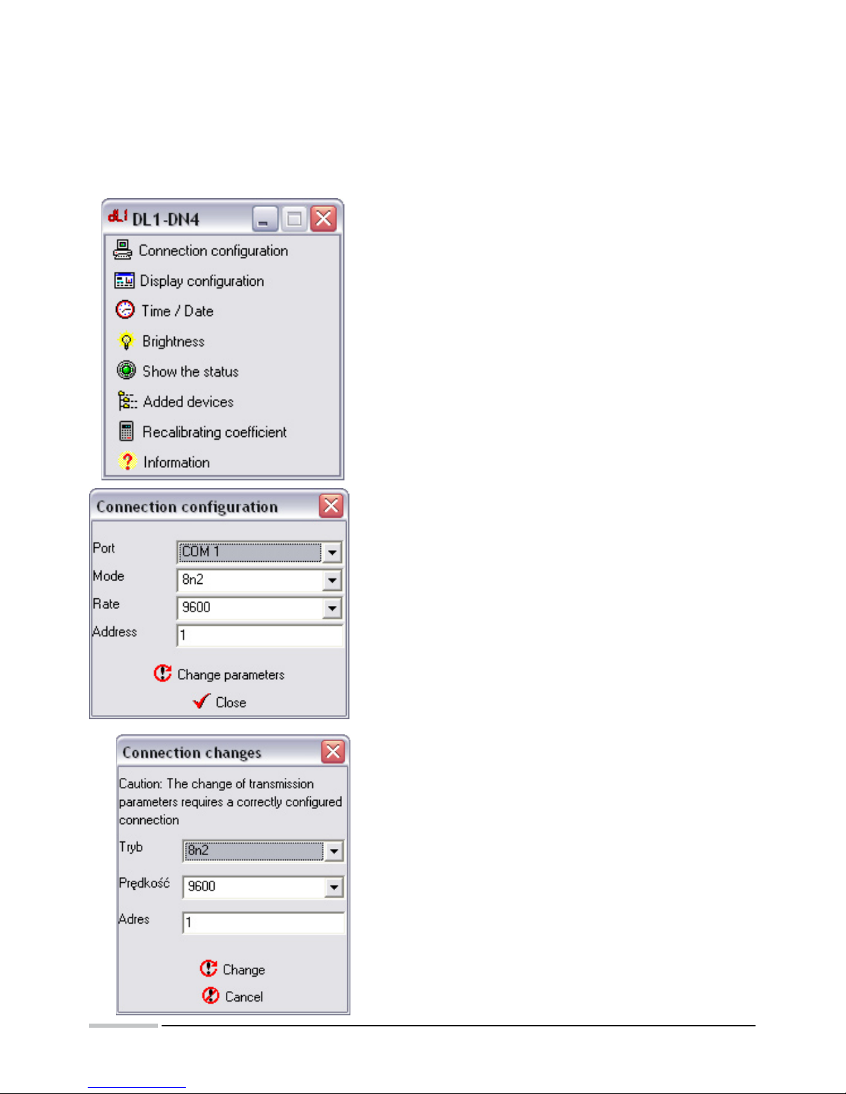
Transmission default parameters of the DL1 display:
- address in the network: 1
- transmission mode: RTU8n2
- baud rate: 9600 bit/sec.
Transmission parameters can be freely changed by
the user. It is recommended to write new and previous
transmission parameters.
The view of the main window of the DL1 program is
presented on the window design.
6.1. Connection configuration
In order to configure connections, one must choose
the option „Connection configuration” from the main
program window. Then, the dialog window presented
on the design will start.
After choosing connection parameters, one can check
the transmission correctness, choosing the option
„Check” or close the window in order to a further work
with the program.
Moreover, the user can also choose the option „Change
parameters” serving to change parameters - see
section 6.2. „Change of transmission parameters..
6.2. Changing transmission parameters”
In order to change connection parameters, one must
choose „Connection configuration” and next, choose
the option Change Parameters in the dialog window
Connection Configuration.
Caution: The change of transmission parameters
can be only made when the connection is correctly
configured..
In the dialog window Connection Change, the user
must give required connection parameters and choose
Change in order to change connection parameters or
Cancel, to resign of introducing changes.
6. CONFIGURATION OF THE DL DISPLAY
The DL11 display is default configured to the display of values being in the register 7500.
The change of display parameters is carried out through the suitable modification of values in
configuring registers. To change parameters, one can use any program destined to read-out and
write registers in MODBUS RTU networks.
Together with the display, a program for the display configuration is delivered, allowing the
modification of all accessible parameters.
Page 11
11
6.3. Display configuration
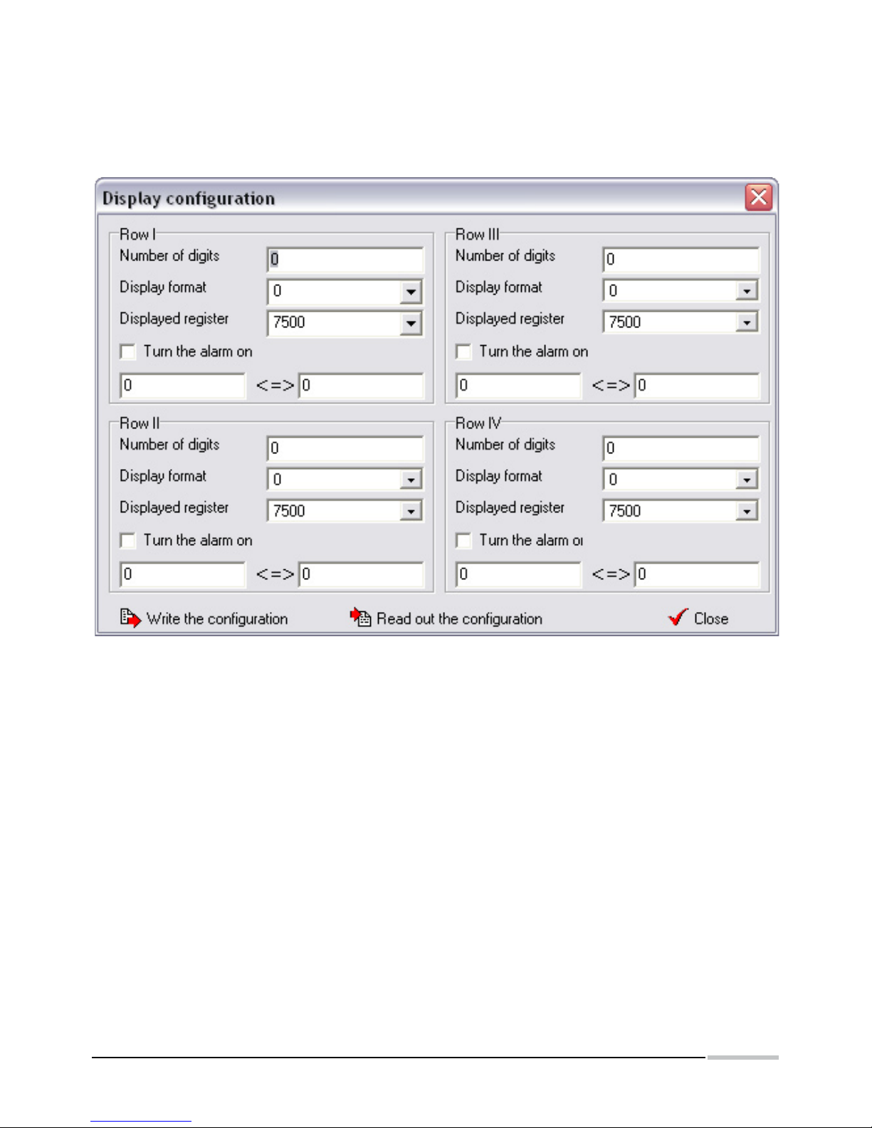
The dialog window Display Configuration serves to the display configuration. The display field can be
freely configured. It is admitted that one display row is destined to display one quantity.
The DL1 program services displays composed maximally of four rows.
In order to change display configuration it is recommended to read out the current configuration,
and next to modify it suitably.
The marking of fields in the dialog window is as follows:
· Number of digits - means the number of digits in the row. The zero value, means the lack of row.
The first row must include one digit at least.
· Display format - the number of digits after the decimal point, defines the number of places after
the decimal point that will be displayed.
· Displayed register - defines the register index, the value of which will be displayed on the display.
· Turn the alarm on - causes the flickering switching of the display after exceeding given values,
signalling in this way the alarm state. Threshold values for the alarm are given in the textual fields
situated under the switch Turn the alarm on.
After carrying out the modification, the configuration write is made by the push-button Write the
configuration.
6.4. Setting time /date
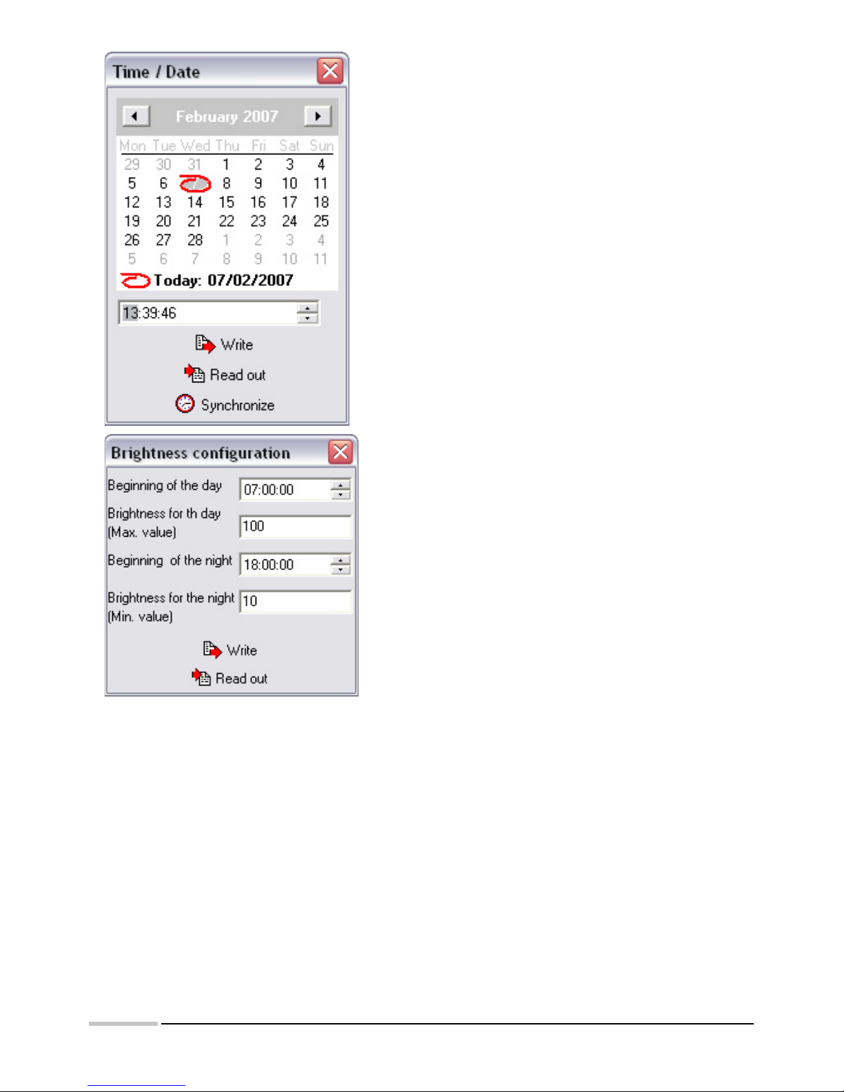
The setting of the current time and date of the internal real time clock is carried out through the choice
of the Time/Date option in the main program window.
The user can select two options of time setting:
Page 12
12
The write of time parameters and their write in the
display or the selection of the Synchronize option,
what will cause the time and date sampling from the
computer and the write of these quantities to the
display.
The selection of the Synchronize option performs the
synchronization of the internal display clock with the
computer clock with a one-second precision, however
the
time write, by giving the date and time value, is carried
out with a one-minute precision (seconds introduced
by the user are omitted).
6.5. Setting the luminosity brightness
DL displays have the possibility to program the luminosity
brightness definition. The luminosity brightness can be
defined in two time periods, named in the program as
brightness for the day and brightness for the night. It
is possible to set the brightness in such a way that the
display will be switched on (increasing the brightness)
in the defined hour and switched off automatically
(decreasing the brightness) in the foreseen hour.
The brightness configuration consists of defining the
starting hour for the day and for the night and defining
the brightness for these periods.
6.6. Display status
The selection of the option Show the Status in the main program window causes the readout of status
registers from the DL display and the display of the window with informing flags. The set flags can be
erased by the marking of the given flag.
The status informs the users about the state of the DL display controller and about the transmission
state between the DL display and devices added to the display.
6.7. Display configuration for the data readout from added devices
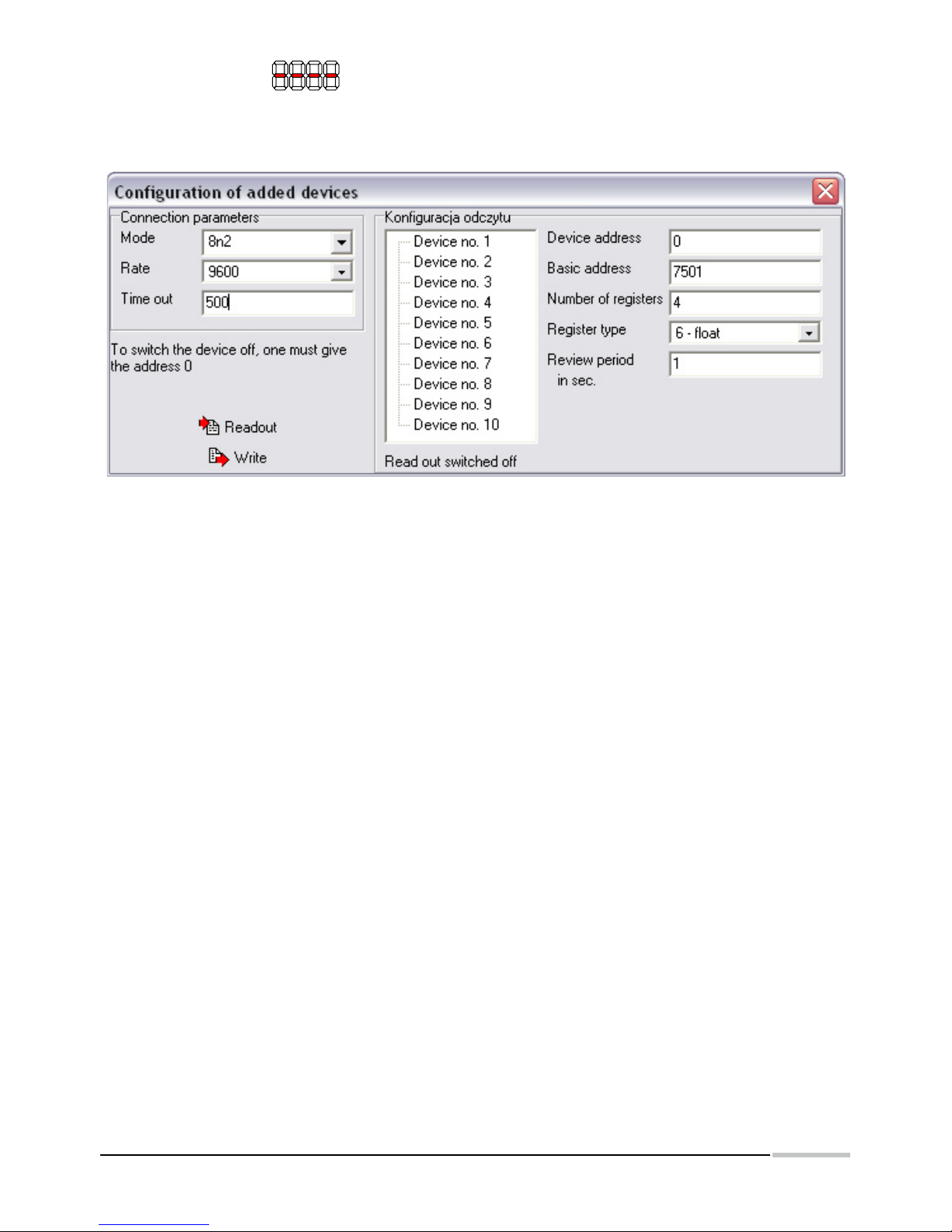
One can configure the display for data readout from external devices working in the MODBUS RTU
mode. All added devices must have identical transmission parameters and different addresses.
The register type, number of registers and register address from which begins the data readout,
is freely configured by the user. The review period (frequency of data readout from the device) is
programmed by the user. Taking in consideration the device response time, it may occur that the time
between successive readouts will be longer than the programmed.
Data readout errors cause the setting of the check bit in the display status register. If errors occur in
the communication with the device which the value is displayed, this will cause the display of an error
Page 13
13
transmission message on the readout field.
The configuration of data readout parameters is carried out in the program after choosing the option
Added Devices from the main program menu what will cause the display of the dialog window
presented below.
The user must define connection parameters, i.e. transmission mode, baud rate and the waiting time to
the device response (time out) given in milliseconds. In order to configure the given device, one must
choose the device to be configured from the list, and next give data readout parameters. To switch the
device off, one must give the zero value as the address.
Before each configuration parameter change, it is recommended to carry out the configuration readout
from the display, and after its modification, choose the option write in order to write changes into the
display.
7. INTERFACE
DL11, DL12 and DL13 displays are equipped with two communication interfaces working in MODBUS
RTU standard. The type of transmission frame and the baud rate are configured through the write of
suitable values into the register.
The interface nr 1 is working all the time in the mode of the slave device (slave) and is destined to
configure display parameters or the change of the displayed quantity.
The interface nr 2 is working in the master mode in the network and serves to the data readout from
additional devices added to the display.
Displays possess the implemented MODBUS function:
· Function 3 - readout of n registers
· Function 16 - write of n registers
· Function 17 - identification of the device.
In order to data readout from external devices, the display unfairs advantage of the function nr 3.
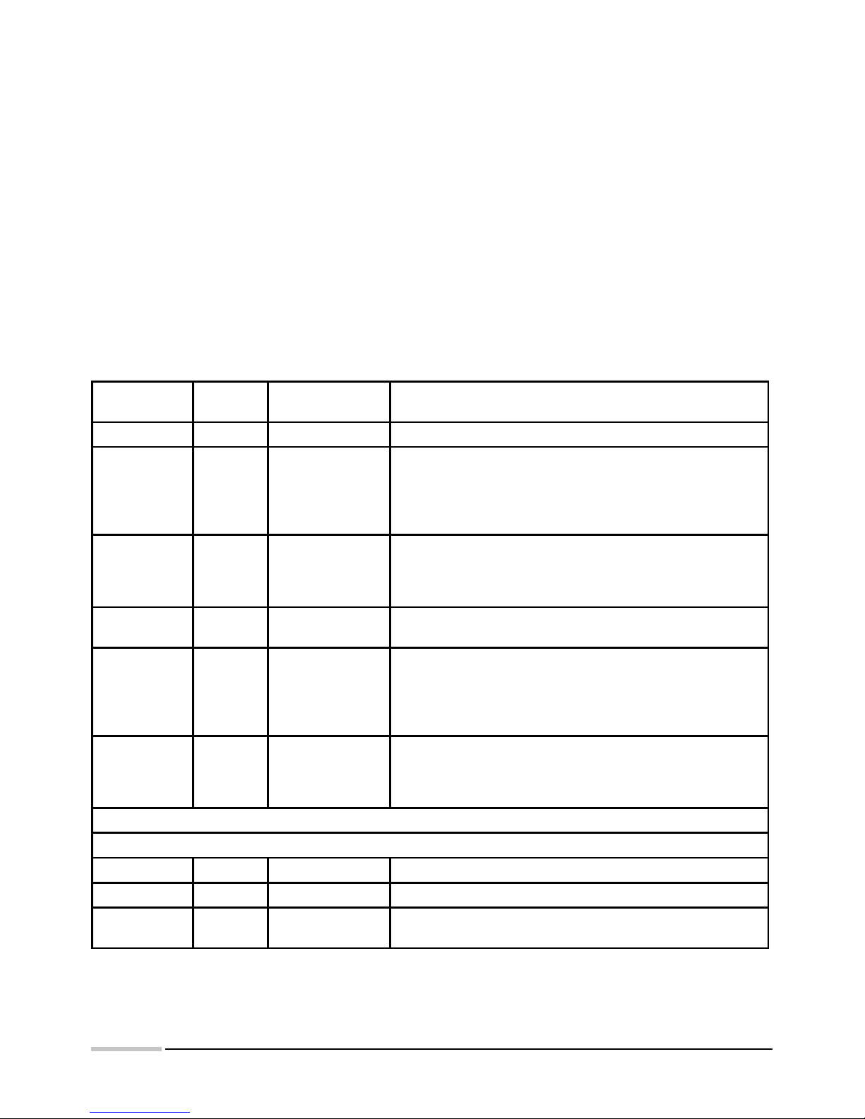
Controller registers are divided into 3 groups:
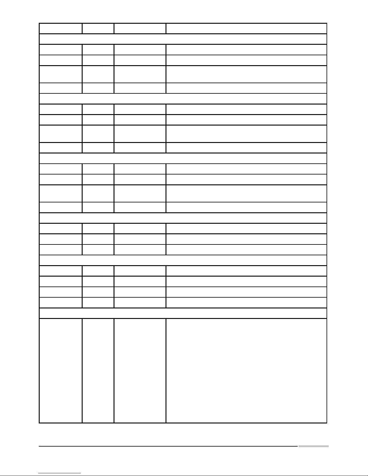
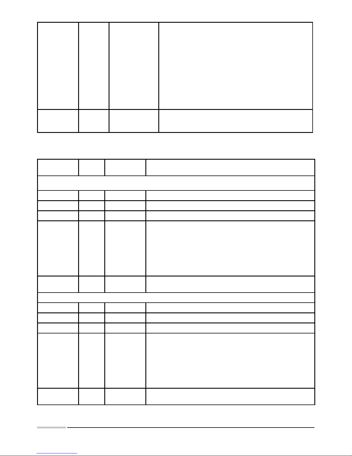
· Registers 4000...4031 - hexadecimal bit registers destined for the configuration of
connection parameters, display and systemic registers,
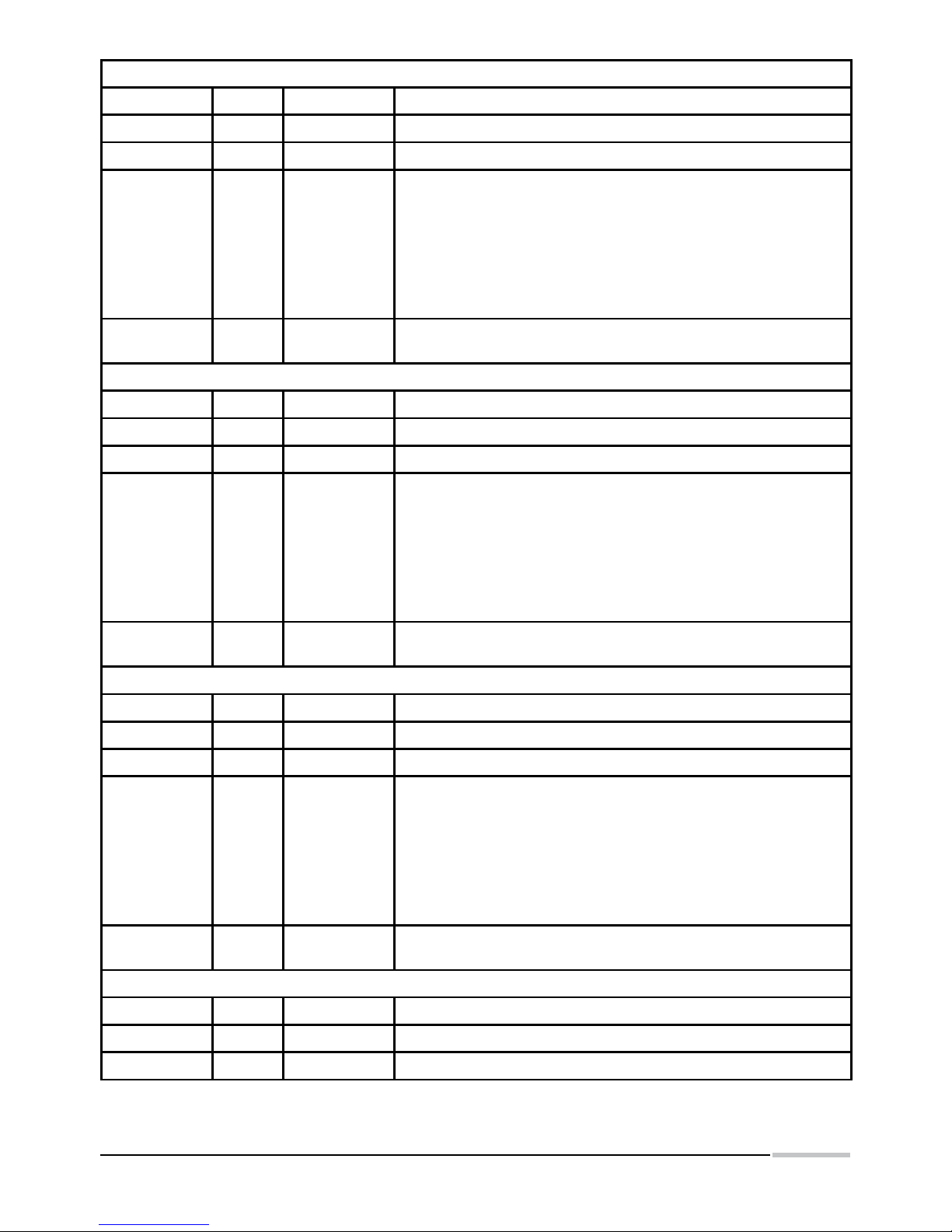
· Registers 4300...4349 - hexadecimal bit registers destined for the readout configuration
from external devices working in MODBUS RTU standard,
· Register 7500...7653 - thirty-two bit registers of float type including data read out from
external devices, measured values and registers of general assignments.
Caution: Values in general registers 7600...7609 have the 1E+20 value after switching the supply on,
Page 14
14
and the value written in these registers is not stored after switching the supply off.
The value introduced in general registers with addresses: 7614...7641, is written in the non-volatile
controller memory.
The switching of the panel on does not cause the lost of values written in these registers.
If the register value to display is higher than 1E+20, then it will be decreased to the 1E+20 value.
Is the register value to display is lower than - 1E+20 , then it will be increased to
the - 1E+20 value.
The data readout from external devices is carried out with a ca 200 ms interval between successive
queries and can be subject to extension in case when the added devices have a long response time
to the query. In case of switching all devices on, or questioning devices with long response time, it can
happen that the time between successive data readouts from the given device will be longer than the
programmed in the panel, what has a relation with response times of devices added to the display and
the number of these devices.
If the added device to the display does not respond or the response is erroneous, then registers with
readout values will be filled with 1E+20 values.
7.1. Registers 4000... 4031
Register
address
Operations Range Description
4000 RW 1…247 Address of interface nr 1 - user’s interface
4001 RW 0…3
Working mode of interface nr 1:
0: RTU 8N1
1: RTU 8N2
2: RTU 8E1
3: RTU 8O1
4002 RW 0…9
Baud rate of interface nr1 [b/s]:
0 – 2400; 1 – 4800; 2 – 9600; 3 – 14400;
4 – 19200; 5 – 28800; 6 – 38400; 7 – 57600;
8 – 76800; 9 – 115200
4003 RW 1…50
Waiting time to the response of slave device for the port 2
expressed as the multiple of 100 ms
4004 RW 0…3
Working mode of interface nr 2
0: RTU 8N1
1: RTU 8N2
2: RTU 8E1
3: RTU 8O1
4005 RW 0…9
Baud rate of interface nr2 [b/s]:
0 – 2400; 1 – 4800; 2 – 9600; 3 – 14400;
4 – 19200; 5 – 28800; 6 – 38400; 7 – 57600;
8 – 76800; 9 – 115200
Konfiguracja of display rows
Row number 1
4006 RW 1…20 Number of digits in the first row
4007 RW 0…3 Display format - number of places after the decimal point
4008 RW 0…149
Number of the register to display, as the shift in respect to the
address 7500
Page 15
15
4009 RW 0,1 Switch the alarm on
Row number II
4010 RW 0…20 Number of digits in the second row
4011 RW 0…3 Display format - number of places after the decimal point
4012 RW 0…149
Number of the register to display, as the shift in respect to the
address 7500
4013 RW 0,1 Switch the alarm on
Row number III
4014 RW 0…20 Number of digits in the third row
4015 RW 0…3 Display format - number of places after the decimal point
4016 RW 0…149
Number of the register to display, as the shift in respect to the
address 7500
4017 RW 0,1 Switch the alarm on
Row number IV
4018 RW 0…20 Number of digits in the fourth row
4019 0…3 Display format - number of places after the decimal point
4020 RW 0…149
Number of the register to display, as the shift in respect to the
address 7500
4021 RW 0,1 Switch the alarm on
Time and date
4022 RW 2001…2100 Current year in the YYYY format
4023 RW 101…1231 Current date in the MMDD format
4024 RW 0000…2359 Current time in the GGMM FORMAT
Luminosity brightness
4025 RW 1…100 Brightness for the day
4026 RW 1…100 Brightness for the night
4027 RW 0000…2359 Beginning of the day
4028 RW 0000…2359 Beginning of the night
Systemic registers
4029 RW No concerns
Status – Successive bits represent flags informing about
events:
Bit 15 – work in service mode - requires service authorization;
Bit 14 – Error of EEPROM memory - manufacturer settings
are restored;
Bit 13 – Error of the RTC clock settings or uncertain settings;
Bit 12 – the summer/winter time was changed or inversely;
Bit 11 – Error of the external lighting sensor (only for options
made with a sensor);
Bit 10 – Break in the supply;
Bit 09 – Measurement error in the line 2 - value beyond the
range;
Bit 08 – Measurement error in the line 1 - value beyond the
range;
Bits 07…00 – no used - always value 0.
Page 16
16
4030 RW No concerns
Status of devices added to the display. Successive bits inform
about the transmission state with slave devices:
Bit 15 – There were transmission errors;
Bit 09 – error of the device number 10;
Bit 08 – error of the device number 9;
Bit 07 – error of the device number 8;
Bit 06 – error of the device number 7;
Bit 05 – error of the device number 6;
Bit 04 – error of the device number 5;
Bit 03 – error of the device number 4;
Bit 02 – error of the device number 3;
Bit 01 – error of the device number 2;
Bit 00 – error of the device number 1;
4031 RW No concerns
Access code to the calibration data and some configuration
settings. In order to change calibration coefficients, one must
introduce the correct password.
7.2. Registers 4300... 4349
Register
address
Opera-
tions
Range Description
Device number 1
4300 RW 0,1…247 Slave device address. 0 - switches the device off
4301 RW 0…65535 Basic address
4302 RW 1…10 Number of read out registers
4303 RW 0…6
Register type:
0 - variable of char type
1 - variable of unsigned char type
2 - variable of integer type
3 - variable of unsigned integer type
4 - variable of long type
5 - variable of unsigned long type
6 - variable of float type
4304 RW 1…60
Review period in seconds. Defines the asking frequency of the slave
device.
Device number 2
4305 RW 0,1…247 Slave device address. 0 - switches the device off
4306 RW 0…65535 Basic address
4307 RW 1…10 Number of read out registers
4308 RW 0…6
Register type:
0 - variable of char type
1 - variable of unsigned char type
2 - variable of integer type
3 - variable of unsigned integer type
4 - variable of long type
5 - variable of unsigned long type
6 - variable of float type
4309 RW 1…60
Review period in seconds. Defines the asking frequency of the slave
device.
Page 17
17
Device number 3
4310 RW 0,1…247 Slave device address. 0 - switches the device off
4311 RW 0…65535 Basic address
4312 RW 1…10 Number of read out registers
4313 RW 0…6
Register type:
0 - variable of char type
1 - variable of unsigned char type
2 - variable of integer type
3 - variable of unsigned integer type
4 - variable of long type
5 - variable of unsigned long type
6 - variable of float type
4314 RW 1…60
Review period in seconds. Defines the asking frequency of the slave
device.
Device number 4
4315 RW 0,1…247 Slave device address. 0 - switches the device off
4316 RW 0…65535 Basic address
4317 RW 1…10 Number of read out registers
4318 RW 0…6
Register type:
0 - variable of char type
1 - variable of unsigned char type
2 - variable of integer type
3 - variable of unsigned integer type
4 - variable of long type
5 - variable of unsigned long type
6 - variable of float type
4319 RW 1…60
Review period in seconds. Defines the asking frequency of the slave
device.
Device number 5
4320 RW 0,1…247 Slave device address. 0 - switches the device off
4321 RW 0…65535 Basic address
4322 RW 1…10 Number of read out registers
4323 RW 0…6
Register type:
0 - variable of char type
1 - variable of unsigned char type
2 - variable of integer type
3 - variable of unsigned integer type
4 - variable of long type
5 - variable of unsigned long type
6 - variable of float type
4324 RW 1…60
Review period in seconds. Defines the asking frequency of the slave
device.
Device number 6
4325 RW 0,1…247 Slave device address. 0 - switches the device off
4326 RW 0…65535 Basic address
4327 RW 1…10 Number of read out registers
Page 18
18
4328 RW 0…6
Register type:
0 - variable of char type
1 - variable of unsigned char type
2 - variable of integer type
3 - variable of unsigned integer type
4 - variable of long type
5 - variable of unsigned long type
6 - variable of float type
4329 RW 1…60
Review period in seconds. Defines the asking frequency of the slave
device.
Device number 7
4330 RW 0,1…247 Slave device address. 0 - switches the device off
4331 RW 0…65535 Basic address
4332 RW 1…10 Number of read out registers
4333 RW 0…6
Register type:
0 - variable of char type
1 - variable of unsigned char type
2 - variable of integer type
3 - variable of unsigned integer type
4 - variable of long type
5 - variable of unsigned long type
6 - variable of float type
4334 RW 1…60
Review period in seconds. Defines the asking frequency of the slave
device.
Device number 8
4335 RW 0,1…247 Slave device address. 0 - switches the device off
4336 RW 0…65535 Basic address
4337 RW 1…10 Number of read out registers
4338 RW 0…6
Register type:
0 - variable of char type
1 - variable of unsigned char type
2 - variable of integer type
3 - variable of unsigned integer type
4 - variable of long type
5 - variable of unsigned long type
6 - variable of float type
4339 RW 1…60
Review period in seconds. Defines the asking frequency of the slave
device.
Device number 9
4340 RW 0,1…247 Slave device address. 0 - switches the device off
4341 RW 0…65535 Basic address
4342 RW 1…10 Number of read out registers
4343 RW 0…6
Register type:
0 - variable of char type
1 - variable of unsigned char type
2 - variable of integer type
3 - variable of unsigned integer type
4 - variable of long type
5 - variable of unsigned long type
6 - variable of float type
Page 19
19
4344 RW 1…60
Review period in seconds. Defines the asking frequency of the slave
device.
Device number 10
4345 RW 0,1…247 Slave device address. 0 - switches the device off
4346 RW 0…65535 Basic address
4347 RW 1…10 Number of read out registers
4348 RW 0…6
Register type:
0 - variable of char type
1 - variable of unsigned char type
2 - variable of integer type
3 - variable of unsigned integer type
4 - variable of long type
5 - variable of unsigned long type
6 - variable of float type
4349 RW 1…60
Review period in seconds. Defines the asking frequency of the slave
device.
7.3. Registers 7500... 7653
Adres rejestru Operacje Zakres Opis
7500 R n.d. Device 1 – First register read out
7501 R n.d. Device 1 – Second register read out.
7502 R n.d. Device 1 – Third register read out
7503 R n.d. Device 1 – fourth register read out
7504 R n.d. Device 1 – Fifth register read out
7505 R n.d. Device 1 – Sixth register read out
7506 R n.d. Device 1 – Seventh register read out
7507 R n.d. Device 1 – Eighth register read out
7508 R n.d. Device 1 – Ninth register read out
7509 R n.d. Device 1 – Tenth register read out
7510 R n.d. Device 2 – First register read out
7511 R n.d. Device 2 – Second register read out.
7512 R n.d. Device 2 – Third register read out
7513 R n.d. Device 2 – fourth register read out
7514 R n.d. Device 2 – Fifth register read out
7515 R n.d. Device 2 – Sixth register read out
7516 R n.d. Device 2 – Seventh register read out
7517 R n.d. Device 2 – Eighth register read out
7518 R n.d. Device 2 – Ninth register read out
7519 R n.d. Device 2 – Tenth register read out
7520 R n.d. Device 3 – First register read out
7521 R n.d. Device 3 – Second register read out.
7522 R n.d. Device 3 – Third register read out
Page 20
20
7523 R n.d. Device 3 – fourth register read out
7524 R n.d. Device 3 – Fifth register read out
7525 R n.d. Device 3 – Sixth register read out
7526 R n.d. Device 3 – Seventh register read out
7527 R n.d. Device 3 – Eighth register read out
7528 R n.d. Device 3 – Ninth register read out
7529 R n.d. Device 3 – Tenth register read out
7530 R n.d. Device 4 – First register read out
7531 R n.d. Device 4 – Second register read out.
7532 R n.d. Device 4 – Third register read out
7533 R n.d. Device 4 – fourth register read out
7534 R n.d. Device 4 – Fifth register read out
7535 R n.d. Device 4 – Sixth register read out
7536 R n.d. Device 4 – Seventh register read out
7537 R n.d. Device 4 – Eighth register read out
7538 R n.d. Device 4 – Ninth register read out
7539 R n.d. Device 4 – Tenth register read out
7540 R n.d. Device 5 – First register read out
7541 R n.d. Device 5 – Second register read out.
7542 R n.d. Device 5 – Third register read out
7543 R n.d. Device 5 – fourth register read out
7544 R n.d. Device 5 – Fifth register read out
7545 R n.d. Device 5 – Sixth register read out
7546 R n.d. Device 5 – Seventh register read out
7547 R n.d. Device 5 – Eighth register read out
7548 R n.d. Device 5 – Ninth register read out
7549 R n.d. Device 5 – Tenth register read out
7550 R n.d. Device 6 – First register read out
7551 R n.d. Device 6 – Second register read out.
7552 R n.d. Device 6 – Third register read out
7553 R n.d. Device 6 – fourth register read out
7554 R n.d. Device 6 – Fifth register read out
7555 R n.d. Device 6 – Sixth register read out
7556 R n.d. Device 6 – Seventh register read out
7557 R n.d. Device 6 – Eighth register read out
7558 R n.d. Device 6 – Ninth register read out
7559 R n.d. Device 6 – Tenth register read out
7560 R n.d. Device 7 – First register read out
7561 R n.d. Device 7 – Second register read out.
Page 21

21
7562 R n.d. Device 7 – Third register read out
7563 R n.d. Device 7 – fourth register read out
7564 R n.d. Device 7 – Fifth register read out
7565 R n.d. Device 7 – Sixth register read out
7566 R n.d. Device 7 – Seventh register read out
7567 R n.d. Device 7 – Eighth register read out
7568 R n.d. Device 7 – Ninth register read out
7569 R n.d. Device 7 – Tenth register read out
7570 R n.d. Device 8 – First register read out
7571 R n.d. Device 8 – Second register read out.
7572 R n.d. Device 8 – Third register read out
7573 R n.d. Device 8 – fourth register read out
7574 R n.d. Device 8 – Fifth register read out
7575 R n.d. Device 8 – Sixth register read out
7576 R n.d. Device 8 – Seventh register read out
7577 R n.d. Device 8 – Eighth register read out
7578 R n.d. Device 8 – Ninth register read out
7579 R n.d. Device 8 – Tenth register read out
7580 R n.d. Device 9 – First register read out
7581 R n.d. Device 9 – Second register read out.
7582 R n.d. Device 9 – Third register read out
7583 R n.d. Device 9 – fourth register read out
7584 R n.d. Device 9 – Fifth register read out
7585 R n.d. Device 9 – Sixth register read out
7586 R n.d. Device 9 – Seventh register read out
7587 R n.d. Device 9 – Eighth register read out
7588 R n.d. Device 9 – Ninth register read out
7589 R n.d. Device 9 – Tenth register read out
7590 R n.d. Device 10 – First register read out
7591 R n.d. Device 10 – Second register read out.
7592 R n.d. Device 10 – Third register read out
7593 R n.d. Device 10 – fourth register read out
7594 R n.d. Device 10 – Fifth register read out
7595 R n.d. Device 10 – Sixth register read out
7596 R n.d. Device 10 – Seventh register read out
7597 R n.d. Device 10 – Eighth register read out
7598 R n.d. Device 10 – Ninth register read out
7599 R n.d. Device 10 – Tenth register read out
7600 RW n.d. General register nr 1
Page 22
22
7601 RW n.d. General register nr 2
7602 RW n.d. General register nr 3
7603 RW n.d. General register nr 4
7604 RW n.d. General register nr 5
7605 RW n.d. General register nr 6
7606 RW n.d. General register nr 7
7607 RW n.d. General register nr 8
7608 RW n.d. General register nr 9
7609 RW n.d. General register nr 10
7610 RW n.d. Alarm 1 – down limitation
7611 RW n.d. Alarm 1 – up limitation
7612 RW n.d. Alarm 2 – down limitation
7613 RW n.d. Alarm 2 – up limitation
7614 RW n.d. Alarm 3 – down limitation
7615 RW n.d. Alarm 3 – up limitation
7616 RW n.d. Alarm 4 – down limitation
7617 RW n.d. Alarm 4 – up limitation
7618 RW n.d. General register
7619 RW n.d. General register
7620 RW n.d. General register
7621 RW n.d. General register
7622 RW n.d. General register
7623 RW n.d. General register
7624 RW n.d. General register
7625 RW n.d. General register
7626 RW n.d. General register
7627 RW n.d. General register
7628 RW n.d. General register
7629 RW n.d. General register
7630 RW n.d. General register
7631 RW n.d. General register
7632 RW n.d. General register
7633 RW n.d. General register
7634 RW n.d. General register
7635 RW n.d. General register
7636 RW n.d. General register
7637 RW n.d. General register
7638 RW n.d. General register
7639 RW n.d. General register
Page 23
23
7640 RW n.d. General register
7641 RW n.d. General register
8. TECHNICAL DATA
Readout field:
Digit height:100 mm
DL11 one row of 3 digits + unit field
DL12 two rows of 3 digits + unit field
DL13 three rows of 3 digits + unit field
Colour of the readout field:
Red, green and yellow - possibility of colour combination for DL12 and DL13
Power consumption:
DL11 < 12VA
DL12 < 24VA
DL13 < 36VA
Communication:
Interface RS-485
Transsmision protocol: MODBUS
Reaction against decay and supply recovery:
Preservation of configuration data in the display.
Dimensions:
DL11 482 x 196 x 41 mm
DL12 482 x 368 x 41 mm
DL13 482 x 540 x 41 mm
Reference conditions and rated operational conditions:
- working temperature 0...
23...50°C
- storage temperature -20... 75°C
- humidity 25... 95%
- supply 85...230...253 V a.c.
- frequency 45...50...60 Hz
- external magnetic field 0...40...400 A/m
- working position any
Standards fulfilled by panels:
Electromagnetic compatibility:
- noise emissions acc. to EN 61000-6-4
- noise immunity acc. to EN 61000-6-2
- resistance to supply decay acc. to EN 61000-6-2
Safety requirements:
acc. to EN 61010-1
· isolation ensured by the housing: basic
· isolation between circuits: basic
· installation category: III
· pollution degree: 2
· maximal working voltage in relation to earth for supply circuits: 300 V, and 50 V for others.
Page 24
24
9. ORDER CODES
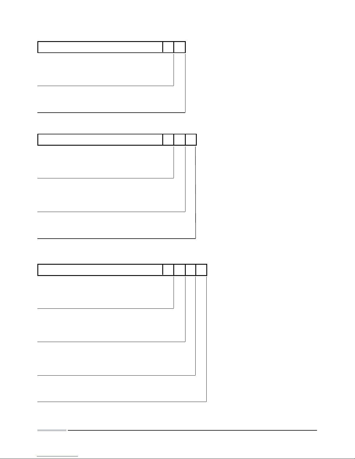
DIGITAL DISPLAY DL11 - X XX
Colour of display field:
Red ...............................................................................R
Yellow ...........................................................................Y
Green............................................................................G
Kind of versions:
Standard ............................................................................. 00
custom-made* ....................................................................XX
Table 1
DIGITAL DISPLAY DL12 - X X XX
Colour of the I display field:
Red ...............................................................................R
Yellow ...........................................................................Y
Green............................................................................G
Colour of the II display field:
Red ...................................................................................... R
Yellow .................................................................................. Y
Green...................................................................................G
Kind of versions:
Standard .....................................................................................00
custom-made* ...........................................................................XX
Table 2
DIGITAL DISPLAY DL13 - X X X XX
Colour of the I display field:
Red ...............................................................................R
Yellow ...........................................................................Y
Green............................................................................G
Colour of the II display field:
Red ...................................................................................... R
Yellow .................................................................................. Y
Green...................................................................................G
Colour of the III display field:
Red ............................................................................................. R
Yellow ......................................................................................... Y
Green.......................................................................................... G
Kind of versions:
Standard ............................................................................................ 00
custom-made* .................................................................................. XX
Table 3
Caution: when ordering, one must give communication parameters
of the measuring devices
Page 25
25
Coding Example
The Code: DL13 - R Y G 00 means:
DL13 - Digital display consisting of 3 rows
R - digits in the upper row are red
Y - digits in the middle row are yellow
G - digits in the lower row are green
00 - in standard version
Other versions of displays are possible acc. customer’s needs after agreeing with the manufacturer.
10. BEFORE A DAMAGE WILL BE DECLARED
If the display remains inconsistently with the customer expectations, one must firstly check the
display configuration.
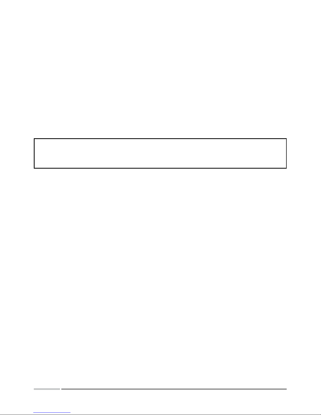
Problem Solution
Lack of display
One must check the connection correctness
Displayed symbol The displayed symbol signals a lack of transmission with
the device which the value has to be displayed from.
One must check the correctness of the interface connec
-
tion and the configuration of additional devices.
Displayed symbol The value to display cannot be situated in the display
field. The value is too high to be displayed.
Lack of communication with the
display
Check the correctness of connections and check the
correctness of transmission parameter settings. In case
when settings are unknown, one must contact the manufacturer or try lately used settings
One must check, if the introduced number of digits for
the given row is not higher than the physical number of
display digits (for the given row).
The displayed result is incomplete.
Lack of the most significant digits
Page 26
26
11. MAINTENANCE AND SERVICE
Displays of DL type do not require a periodical maintenance. One cannot use solvents, petrols, corrosive
means, which can damage painted surfaces of the display or the frontal glass. Antielectrostatic cleaning
foams are the most suitable to clean the display.
When washing the display, one must take care that moisture does not penetrate inside the display.
In case of some incorrect operations:
1. After the dispatch date and within the period stated in the guarantee card
One should return the device to the LUMEL’s Quality Inspection Dept.
If the device has been used in compliance with the instructions, LUMEL S.A. guarantees to repair it
free of charge.
The disassembling of the housing causes the cancellation of the granted guarantee.
2. After the guarantee period:
One should send the device to repair it in an authorized service workshop. Spare parts are available
for the period of five years from the date of purchase.
LUMEL S.A. policy is one of continuous improvement and we reserve the right to make
changes in design and specifications of any products as engineering advances or
necessity requires and revise the above specifications without notice.
Page 27

27
Page 28
28
QUALITY PROCEDURES
According to ISO 9001 and ISO 14001 international requirements.
All our instruments have CE mark .
For more information, please write to or phone our Export Department
Lubuskie Zak³ady Aparatów Elektrycznych LUMEL S.A.
ul. Sulechowska 1, 65-022 Zielona Góra, Poland
Tel.: (48-68) 329 51 00 (exchange)
Fax: (48-68) 329 51 01
e-mail:[email protected]
http://www.lumel.com.pl
Export Department
:
Tel.: (48-68) 329 53 02 or 53 04
Fax: (48-68) 325 40 91
e-mail: [email protected]
MEASUREMENT
CONTROL
RECORDING
SALES PROGRAM
n DIGITAL and BARGRAPH PANEL METERS
n MEASURING TRANSDUCERS
n ANALOG PANEL METERS (DIN INSTRUMENTS)
n ANALOG and DIGITAL CLAMP-ON METERS
n INDUSTRIAL and HOUSEHOLD CONTROLLERS
n CHART AND PAPERLESS RECORDERS
n POWER CONTROL UNITS and RELAYS
n AUTOMOTIVE DASHBOARD INDICATORS
n ELECTRONIC WATT-HOUR-METERS
n ACCESSORIES FOR MEASURING INSTRUMENTS
n MEASURING SYSTEMS (ENERGY, HEAT, CONTROL)
n CUSTOM-MADE PRODUCTS
WE ALSO OFFER OUR SERVICES IN THE PRODUCTION OF:
n ALUMINIUM ALLOY PRESSURE CASTINGS
n PRECISION ENGINEERING AND THERMOPLASTICS PARTS
n ASSEMBLY OF PC BOARDS and ELECTRONIC DEVICES
§ CUSTOM-MADE PRODUCTS
 Loading...