

Page 1
+
SAFETY AND OPERATING MANUAL
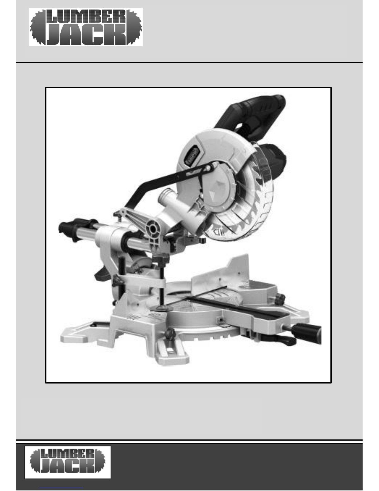
SINGLE BEVEL SLIDING COMPOUND MITRE SAW
SCMS210SB
ORIGINAL INSTRUCTIONS
SCMS210SB
Page 2
TABLE OF CONTENTS
Welcome to Lumberjack!
Dear customer, Congratulations on your purchase. Before using the
Product for the first time please be sure to read these instructions for use.
They provide you with all information necessary for using the product safely and to
ensure its long service life.
Closely observe all safety information in these instructions!
General Power Tool Safety Warnings………………………………….…......01
Symbols & Cable Rating Chart ……….…………………………………….………06
Machine Details and Product features……….…………………………….….07
Assembly……………………………………………………………………………………..08
Operation…………………………………………………………………………………….10
Working advice……………………………………………………………………………11
Maintenance and Service…………………………………………………………….12
Lumberjack Guarantee…………………………………………………………………13
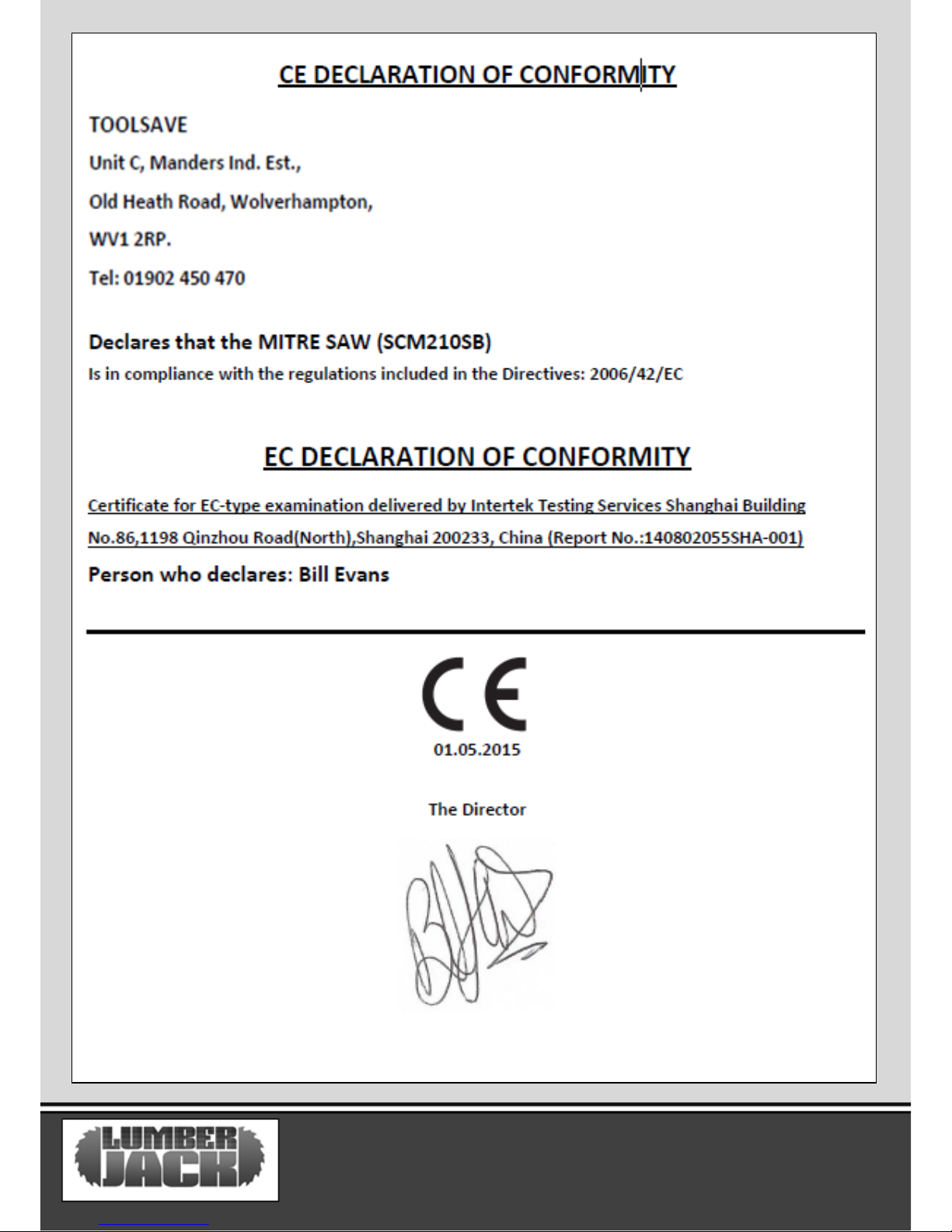
Declaration of conformity……………………………………………………………15
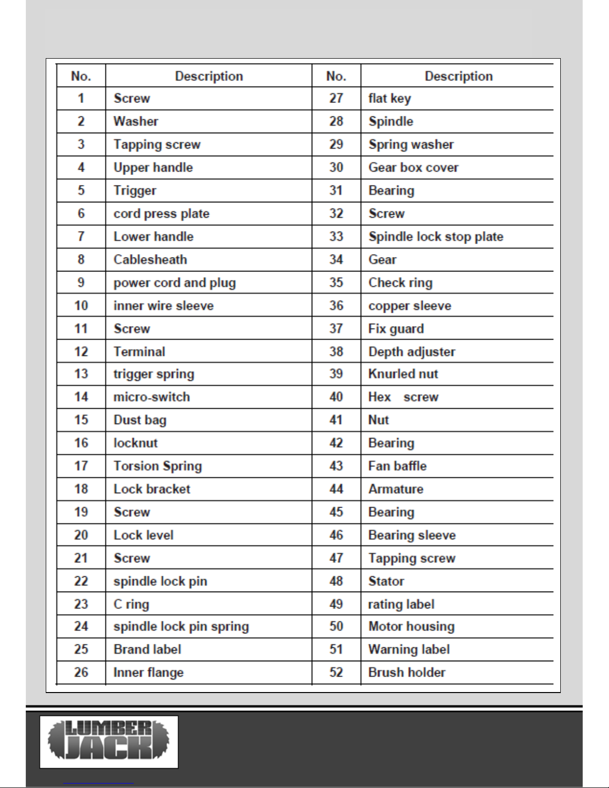
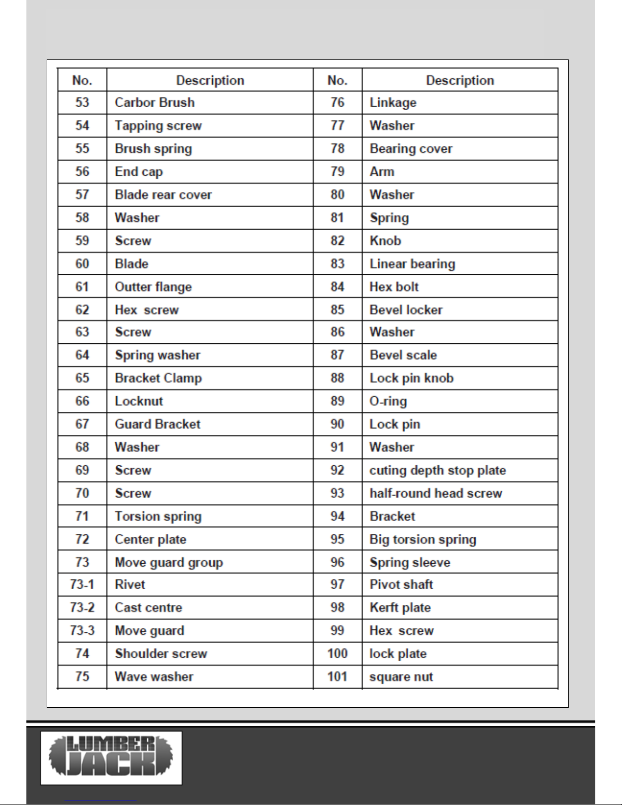
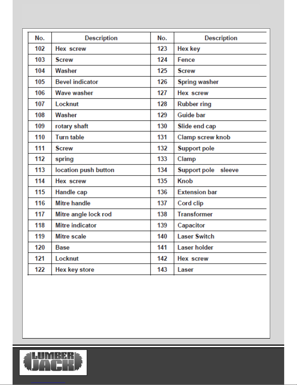
Parts list……………………………………………………………………………………...16
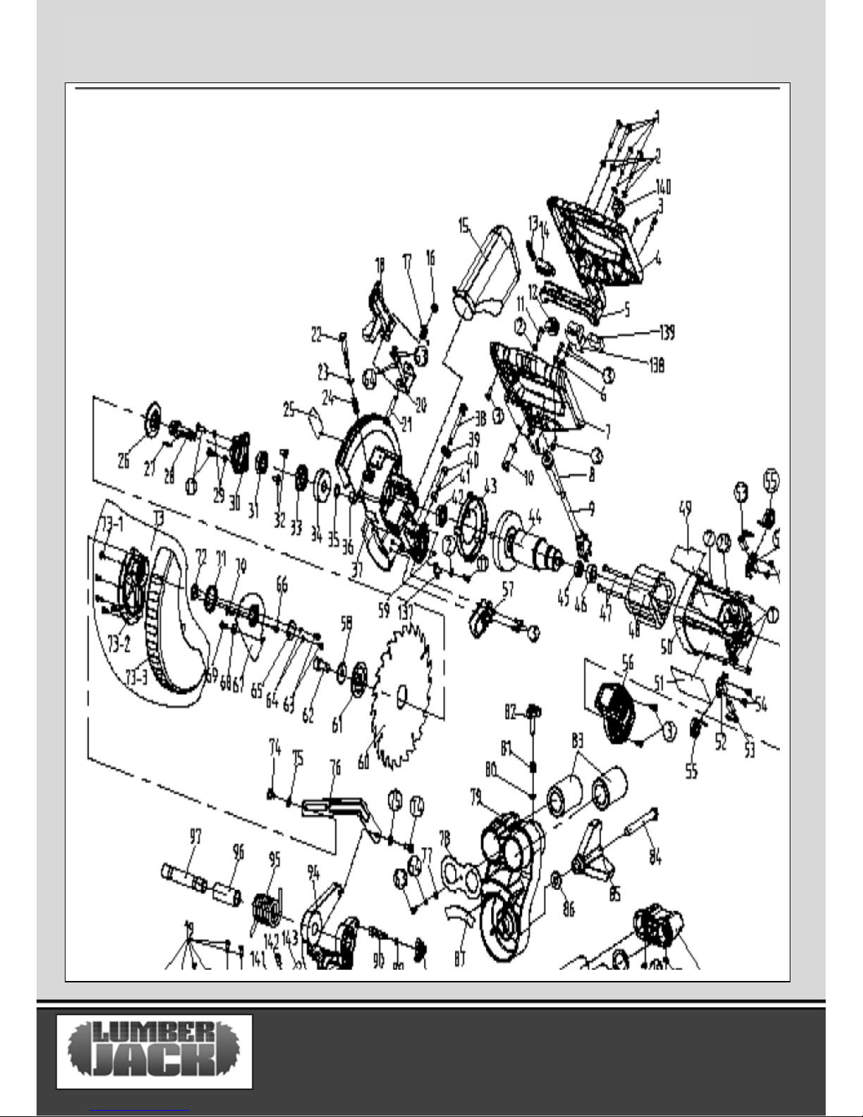
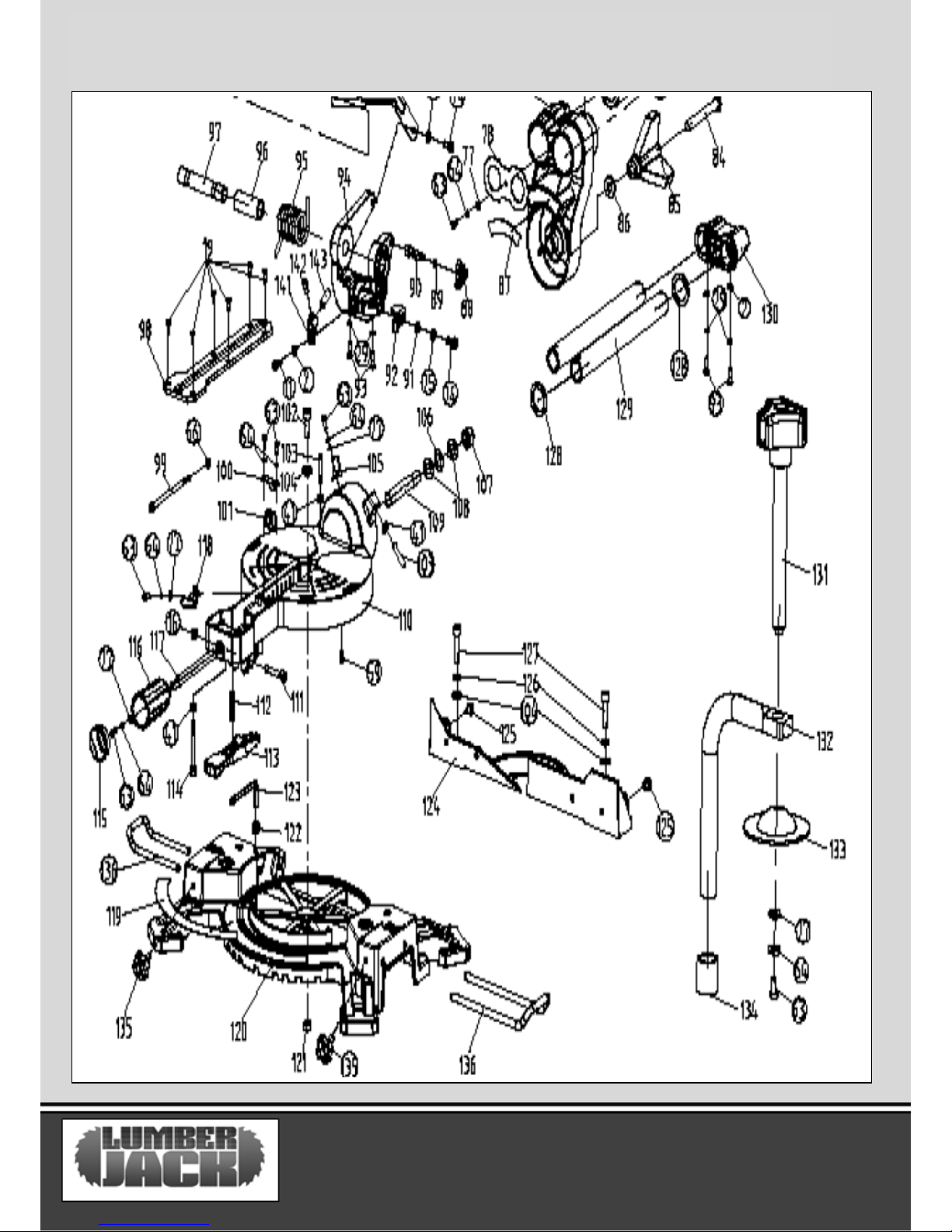
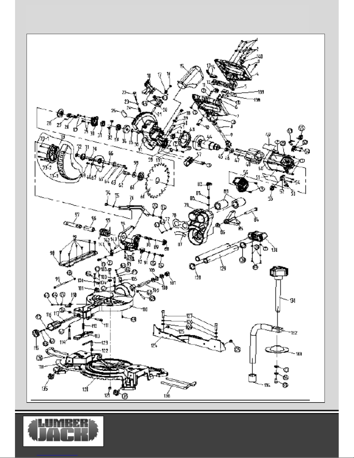
Parts Diagram………………………………………………………………………………19
SCMS210SB
Page 3
SCMS210SB 01
GENERAL POWER TOOL SAFETY WARNINGS
WARNING Read all safety warnings and
all instructions. Failure to follow the warnings
and instructions may result in electric shock, fire
and/or serious injury.
Save all warnings and instructions for
future reference. The term "power tool" in
the warnings refers to your electric (corded)
power tool or battery-operated (cordless) power
tool.
1. Work area safety
a) Keep work area clean and well lit. Cluttered
or dark areas invite accidents.
b) Do not operate power tools in explosive
atmospheres, such as in the presence of
flammable liquids, gases or dust. Power tools
create sparks which may ignite the dust or
fumes.
c) Keep children and bystanders away while
operating a power tool. Distractions can cause
you to lose control.
2. Electrical safety
a) Power tool plugs must match the outlet.
Never modify the plug in any way. Do not use
any adapter plugs with grounded power tools.
Unmodified plugs and matching outlets will
reduce risk of electric shock.
b) Avoid body contact with grounded surfaces,
such as pipes, radiators, ranges and
refrigerators. There is an increased risk of
electric shock if your body is grounded.
c) Do not expose power tools to rain or wet
conditions. Water entering a power tool will
increase the risk of electric shock.
d) Do not abuse the cord. Never use the cord for
carrying, pulling or unplugging the power tool.
Keep cord away from heat, oil, sharp edges or
moving parts. Damaged or entangled cords
increase the risk of electric shock.
e) When operating a power tool outdoors, use an
extension cord suitable for outdoor use. Use of a
cord suitable for outdoor use reduces the risk of
electric shock.
f) If operating a power tool in a damp location is
unavoidable, use a residual current device (RCD)
protected supply. Use of an RCD reduces the risk
of electric shock.
3. Personal safety
a) Stay alert, watch what you are doing and use
common sense when operating a power tool. Do
not use a power tool while you are tired or under
the influence of drugs, alcohol or medication. A
moment of inattention while operating power
tools may result in serious personal injury.
b) Use personal protective equipment. Always
wear eye protection. Protective equipment such
as dust mask, non-skid safety shoes, hard hat, or
hearing protection used for appropriate conditions
will reduce personal injuries.
c) Prevent unintentional starting. Ensure the
switch is in the off position before connecting to
power source and/or battery pack, picking up or
carrying the tool. Carrying power tools with your
finger on the switch or energising power tools that
have the switch on invites accidents.
d) Remove any adjusting key or wrench before
turning the power tool on. A wrench or a key left
attached to a rotating part of the power tool may
result in personal injury.
Page 4
SCMS210SB 02
e) Do not overreach. Keep proper footing and
balance at all times. This enables better control
of the power tool in unexpected situations.
f) Dress properly. Do not wear loose clothing or
jewellery. Keep your hair, clothing and gloves
away from moving parts. Loose clothes,
jewellery or long hair can be caught in moving
parts.
g) If devices are provided for the connection of
dust extraction and collection facilities, ensure
these are connected and properly used. Use of
dust collection can reduce dust-related hazards.
4. Power tool use and care
a) Do not force the power tool. Use the correct
power tool for your application. The correct
power tool will do the job better and safer at the
rate for which it was designed.
b) Do not use the power tool if the switch does
not turn it on and off. Any power tool that
cannot be controlled with the switch is
dangerous and must be repaired.
c) Disconnect the plug from the power source
and/or the battery pack from the power tool
before making any adjustments, changing
accessories, or storing power tools. Such
preventive safety measures reduce the risk of
starting the power tool accidentally.
d) Store idle power tools out of the reach of
children and do not allow persons unfamiliar
with the power tool or these instructions to
operate the power tool. Power tools are
dangerous in the hands of untrained users.
e) Maintain power tools. Check for misalignment
or binding of moving parts, breakage of parts and
any other condition that may affect the power
tool’s operation. If damaged, have the power tool
repaired before use. Many accidents are caused
by poorly maintained power tools.
f) Keep cutting tools sharp and clean. Properly
maintained cutting tools with sharp cutting edges
are less likely to bind and are easier
g) Use the power tool, accessories and tool bits
etc. in accordance with these instructions, taking
into account the working conditions and the work
to be performed. Use of the power tool for
operations different from those intended could
result in a hazardous situation.
5. Service
a) Have your power tool serviced by a qualified
repair person using only identical replacement
parts. This will ensure that the safety of the power
tool is maintained.
b) If the replacement of the supply cord is
necessary, this has to be done by the
manufacturer or its agent in order to avoid a
safety hazard.
6. Battery Tool Use and Care
a) Recharge only with the charger specified by
the manufacturer. A charger that is suitable for
one type of battery pack may create a risk of fire
when used with another battery pack.
b) Use power tools only with specifically
designated battery packs. Use of any other
battery packs may create a risk of injury or fire.
GENERAL POWER TOOL SAFETY WARNINGS
Page 5
SCMS210SB 03
GENERAL POWER TOOL SAFETY WARNINGS
c) When Battery pack is not in use, keep it away
from other metal objects, like paper clips, coins,
keys, nails, screws or other small metal object
that can make a connection from one terminal
to another. Shorting the battery terminals
together may cause burns or a fire.
D) User abusive conditions, liquid may be
ejected from the battery; Avoid contact. If
contact accidentally occurs, flush with copious
amounts of water. If liquid contacts eyes, seek
medical help immediately. Liquid ejected from
the batter may cause irritation or burns.
7. Additional Safety and working
Instructions
7.1. Dust from materials such as lead-containing
coatings, some wood types, minerals and
metals can be harmful to one’s health and
cause allergic reactions, leading to respiratory
infections and/or cancer. Materials containing
asbestos may only be worked by specialists.
Observe the relevant regulations in your country
for the materials to be worked.
7.2. Prevent dust accumulation at the
workplace. Dust can easily ignite.
8 Safety Warnings for Chop and Mitre
Saws
8.1 Never stand on the power tool. Serious
injuries can occur when the power tool tips over
or when inadvertently coming into contact with
the saw blade.
8.2 Make sure that the guard operates properly
and that it can move freely. Never lock the
guard in place when opened.
8.3 Never remove cutting remainders, wood
chips, etc. from the sawing area while the
machine is running. Always guide the tool arm
back to the neutral position first and then switch
the machine off.
8.4 Guide the saw blade against the work piece
only when the machine is switched on.
Otherwise there is damage of kickback, when the
saw blade becomes wedged in the work piece.
8.5 Keep handles dry, clean, and free from oil and
grease. Greasy, oily handles are slippery causing
loss of control.
8.6 Operate the power tool only when the work
area to the work piece is clear of any adjusting
tools, wood chips, etc. Small pieces of wood or
other objects that come in contact with the
rotating saw blade can strike the operator with
high speed.
8.7 Keep the floor free of wood chips and
material remainders. You could slip or trip.
8.8 Always firmly clamp the piece to be worked.
Do not saw work pieces that are too small to
clamp. Otherwise, the clearance of your hand to
the rotating saw blade is too small.
8.9 Use the machine only for cutting the
materials listed under Intended Use.
Otherwise, the machine can be subject to
overload.
8.10 If the saw blade should become jammed,
switch the machine off and hold the work piece
until the saw blade comes to a complete stop. To
prevent kickback, the work piece may not be
moved until after the machine has come to a
complete stop. Correct the cause for the jamming
of the saw blade before restarting the machine.
Page 6
SCMS210SB 04
GENERAL POWER TOOL SAFETY WARNINGS
8.11 Do not use dull, cracked, bent or damaged
saw blades. Unsharpened or Improperly set saw
blades produce narrow kerf causing excessive
friction, blade binding and kickback.
8.12 Always use saw blades with correct size
and shape (diamond versus round) of bore.
Saw blades that do not match the mounting
hardware of the saw will run eccentrically,
causing loss of control.
8.13 Do not use high speed steel (HSS) saw
blades. Such saw blades can easily break.
8.14 Do not touch the saw blade after working
before it has cooled. The saw blade becomes
very hot while working.
8.15 Never operate the machine without the
insert plate. Replace a defective insert plate.
Without flawless insert plates, injuries are
possible from the saw blade.
8.16 Check the cable regularly and have a
damaged cable repaired only through an
authorised customer service agent. Replace
damaged extension cables. This will ensure that
the safety of the power tool is maintained.
8.17 Store the machine in a safe manner when
not being used. The storage location must be
dry and lockable. This prevents the machine
from storage damage, and from being operated
by untrained persons.
8.18 Secure the work piece. A work piece
clamped with clamping devices or in a vice is
held more secure than by hand.
8.19 Never leave the machine before it has
come to a complete stop. Cutting tools that are
still running can cause injuries.
8.20 Never use the machine with a damaged
cable. Do not touch the damaged cable and pull
the mains plug when the cable is damaged while
working. Damaged cables increase the risk of an
electric shock.
9. Safety Warnings for Lasers
The mitre saw has a built‐in laser light. The laser is
CLASS 2. These lasers do not normally present an
optical hazard. However, DO NOT stare at the
beam, as this can cause flash blindness.
9.1 Do not remove or deface any product labels.
Removing product labels increases the risk of
exposure to laser radiation.
9.2 The laser beam can be harmful to the eyes.
Always avoid direct expose to eyes. Do not project
the laser beam directly into the eyes or at any
object other than the work piece.
9.3 Do not look directly into the laser‐beam‐
output aperture during operation.
9.4 Turn the laser on only when making cuts.
The laser on the mitre saw is not a toy. Always
keep it out of the reach of children. The laser light
emitted from this device should never be directed
toward any person for any reason.
9.5 Always turn the laser beam off when it is not
in use. Leaving the tool on increases the risk of
someone inadvertently staring into the laser’s
beam.
9.6 Be sure that the laser beam is aimed at a
work piece (such as wood or a rough‐coated
surface) that does not have a reflective Surface
Page 7
SCMS210SB 05
GENERAL POWER TOOL SAFETY WARNINGS
9.7 Do not use on materials that have shiny,
reflective surfaces, such as sheet metal.
The reflective surface could reflect the beam
back at the operator. Be aware that laser light
reflected off of a mirror or any other reflective
surfaces can also be dangerous.
9.8 Always wear laser‐protective eyewear
when working on or near reflective surfaces.
9.9 Do not attempt to activate the laser when
the tool housing is removed.
9.10 The laser is activated by means of a
button switch that is independent of the main
switch for the saw.
9.11 Do not replace the laser light assembly
with a different one. Any repairs must be
carried out by the laser manufacturer or an
authorized service agent.
9.12 Do not attempt to repair the laser guide
by yourself.
9.13 Do not attempt to change any parts of
the laser guide.
10. Using an Extension Cable.
10.1. If an extension cable is required, use an
approved triple core extension cable suitable for
the power input of the tool.
10.2. Grounded tools always require a three wire
extension cable.
10.3. As the distance from the supply outlet
increases you must use a heavier gauge extension
cable. Using extension cables with inadequately
sized wire causes a serious drop in voltage,
resulting in loss of power and possible tool
damage.
10.4. The smaller the gauge number of the wire
the greater the capacity of the cord.
10.5. When using a cable reel, always unwind the
cable completely.
Page 8
SYMBOLS AND POWER RATING CHART
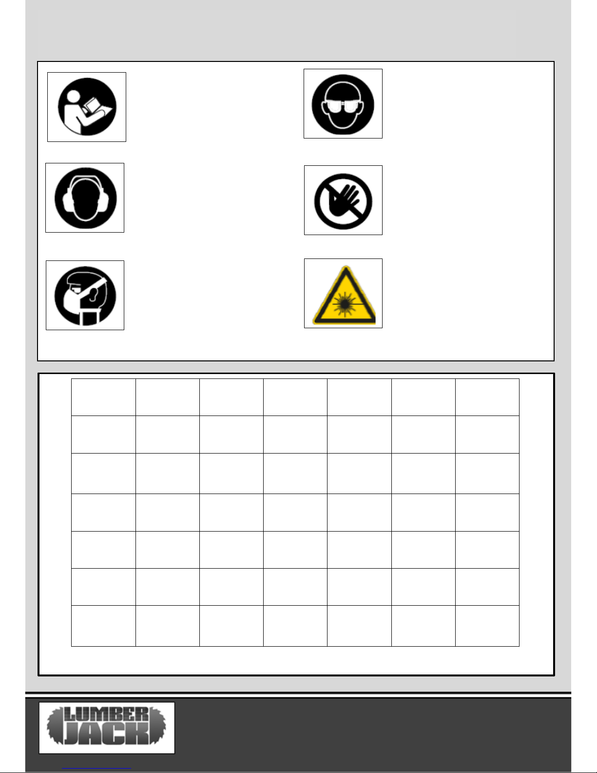
Danger! – Read the operating
instructions to reduce the risk of
injury.
Caution! Wear safety goggles.
Caution! Wear ear defenders. The
impact of noise can cause
damage to hearing.
Amperes
7.5M
15M
25M
30M
45M
60M
0 – 2.0
6 6 6 6 6
6
2.1 – 3.4
6 6 6 6 6
6
3.5 - 5.0
6 6 6 6 10
15
5.1 – 7.1
10
10
10
10
15
15
7.1 – 12.0
15
15
15
15
20
20
12.1 – 20.0
20
20
20
20
25
-
Caution! Risk of Injury! Do
not reach into the running
saw blade.
Caution! Wear a dust mask.
SCMS210SB
06
Caution: Laser radiation. Do
not look into the beam! Laser
class 2 product!
SCMS210SB 06
Page 9
SCMS210SB
08
SCMS210SB 07
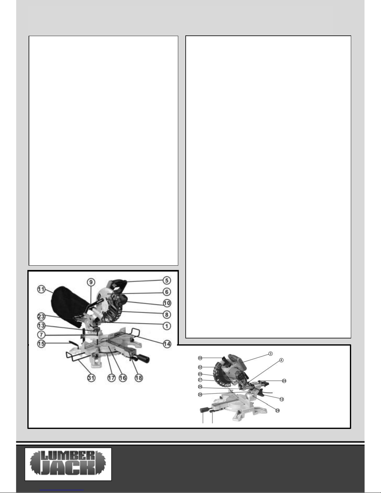
MACHINE DETAILS AND PRODUCT FEATURES
Machine Details
Specifications:
Mains Voltage ‐ 230V / 50Hz
Power Consumption ‐ 1500W
Blade Spec ‐ 210x30x3.2mm/24T
Cutting Capacity:
At 0 / 0 degrees ‐ 210x70mm
At 0 / +45 degrees ‐ 147x70mm
At +45 / 0 degrees ‐ 210x35mm
At +45 / +45 degrees ‐ 147x35mm
Gross Weight ‐ 11.3kg
Nett Weight ‐ 9.8kg
Package Contents:
210mm Mitre saw
Dust Bag
“G” clamp
Hex Key
2 x Extension Bars
Product Features
1. Laser light
2. Laser light on/off switch
3. Saw arm
4. Release knob
5. Operating handle
6. Upper fixed blade guard
7. “G” Clamp
8. Rotating blade guard
9. Guard retraction arm
10. Blade bolt cover
11. Dust bag
12. Bevel lock
13. Bevel scale
14. Fence
15. 6mm Hex key
16. Mitre table
17. Mitre scale
18. Table insert
19. Switch trigger
20. Mitre lock knob
21. Mitre latch
22. Spindle lock
23. Slide bars
24. Slide lock
25. Trenching depth adjustment screw
26. Trenching stop
27. Trenching depth lock nut
28. 45°Bevel adjustment screw
29. 0°Bevel adjustment screw
30. Release latch
31. Side support bars (x2)
Intended Use
The power tool is intended as a stationary machine for making
straight lengthways and crossways cuts in wood. In this, mitre
angles from –45° to +45° as well as bevel angles from ‐45° to 45°
are possible. The capacity of the power tool is designed for
sawing hardwood and softwood. The power tool is not suitable
for cutting aluminium or other non‐ferrous metals or alloys.
Page 10
SCMS210SB 08
ASSEMBLY
Avoid unintentional starting of the
machine. During assembly and for all
work on the machine, the power plug
must not be connected to the mains
supply.
Carefully remove all parts included in the
delivery from their packaging.
Remove all packaging material from the
machine and the accessories provided.
Before starting the operation of the machine
for the first time, check if all parts listed in the
box content section have been supplied.
Note: Check the power tool for possible
damage. Before further use the machine,
check that all protective devices are fully
function. Any lightly damaged parts must be
carefully checked to ensure flawless operation
of the tool. All parts must be properly
mounted and all conditions fulfilled that
ensure faultless operation.
Damaged protective devices and parts must be
immediately replaced by an authorised service
centre.
Always tighten the locking knob (20) &
(12) firmly before sawing. Otherwise the
saw blade can become wedged in the
workpiece.
Transportation
Lift the mitre saw only when the saw arm is
locked in the down position, the saw is
switched off and the plug is removed from the
power point. Only lift the saw by the operating
handle (5) or outer castings. Do not lift the saw
using the guards.
Stationary or Flexible Mounting
To ensure safe handling, the machine
must be mounted on a level and stable
surface (e.g. workbench) prior to using.
Mounting to a Working Surface
– Fasten the power tool with suitable screw
fasteners to the working surface. The mounting
holes serve for this purpose.
– Clamp the power tool with commercially
available screw clamps by the feet to the
working surface.
Mounting to a Saw Stand
Any universal saw stand which will accept
mounting holes 404mm wide by 263mm in
length will suffice.
Read all safety warnings and instructions
included with the worktable. Failure of
observing safety warnings and instructions can
lead to electrical shock, fire and/or cause serious
injuries.
Assemble the worktable properly before
mounting the power tool. Perfect assembly
is important in order to prevent the risk of
collapsing.
– Mount the power tool in transport position on
the saw stand.
Dust/Chip Extraction
Dusts from materials such as lead‐containing
coatings, some wood types, minerals and metal
can be harmful to one’s health.
Touching or breathing‐in the dusts can cause
allergic reactions and/or lead to respiratory
infections of the user or bystanders.
Page 11
Certain dusts, such as oak or beech dust, are
considered as carcinogenic, especially in
connection with wood‐treatment additives
(chromate, wood preservative). Materials
containing asbestos may only be worked by
specialists.
– Always use dust extraction or the Dust bag
provided (11).
– Provide for good ventilation of the working
place.
– It is recommended to wear a P2 filter‐class
respirator.
Observe the relevant regulations in your
country for the materials to be worked.
The dust/chip extraction can be blocked by
dust, chips or workpiece fragments.
– Switch the machine off and pull the mains
plug from the socket outlet.
– Wait until the saw blade has come to a
complete stop.
– Determine the cause of the blockage and
correct it.
Integrated Dust Extraction.
– Insert the dust bag firmly onto the machine
During sawing, the dust bag must never come
in contact with moving tool components.
Always empty the dust bag in good time.
External Dust Extraction
For dust extraction, you can also connect the
extraction port to a vacuum hose (internal Ø
40 mm).
The dust extractor must be suitable for the
material being worked. When vacuuming dry
dust that is especially detrimental to health or
carcinogenic, use a special dust extractor.
Changing the Blade
– Make sure that the electrical plug is removed
from the power point.
– Push down on the operating handle (3) and
pull the release knob (4) to disengage the saw
arm (3).
– Raise the saw arm (3) to its highest position.
– Loosen the cover plate screw about 2 turns
with a Phillips screwdriver. Do not remove this
screw from the tool.
– Pull the rotating blade guard (8) down.
When the rotating blade guard (8) is positioned
over the upper fixed blade guard
(6 it is possible to access the blade bolt.
– Lift and hold up the lower blade guard (8) to
expose the threaded blade bolt.
– Hold the rotating guard (8) up and press the
spindle lock button (22). Rotate the blade until
the spindle locks.
– Use the 6 mm hex key provided to loosen and
remove the blade bolt. (Loosen in a clockwise
direction as the blade screw has a left hand
thread).
– Remove the flat washer, outer blade washer
and the blade.
–Wipe a drop of oil onto the inner blade washer
and the outer blade washer where they contact
the blade.
– Fit the new blade onto the spindle taking care
that the inner blade washer sits behind the
blade.
– Replace the outer blade washer.
– Depress the spindle lock button (22) and
replace the flat washer and blade bolt.
– Use the 6 mm hex key to tighten the blade bolt
securely (tighten in an anti‐clockwise direction).
– Lower the blade guard hold the rotating lower
blade guard (8) and blade bolt cover
(10) in position and tighten the fixing screw to
secure the blade bolt cover in position.
SCMS210SB 09
ASSEMBLY
Page 12
SCMS210SB 10
OPERATION
– Check that the blade guard operates
correctly and covers the blade as the saw arm
is lowered.
– Connect the saw to the power supply and
run the blade to make certain that it is
operating correctly.
Operation
Setting the Table Square with the
Blade
– Make sure that the electrical plug is removed
from the power point.
– Push the saw arm (3) down to its lowest
position and engage the release knob (4) to
hold the saw arm in the transport position.
– Loosen the mitre locks (20) and lifting up the
mitre latch (21).
– Rotate the table (16) until the pointer is
positioned at 0°
– Release mitre latch (21) and tighten the
mitre locks (20).
– Loosen the bevel lock (12) and set the saw
arm (3) at 0°bevel (the blade at 90°to the
mitre table). Tighten the bevel lock (12).
– Place a set square against the table (16) and
the flat part of the blade.
– Rotate the blade by hand and check the
blade‐to‐table alignment at several points.
– The edge of the set square and the saw blade
should be parallel.
– If the saw blade angles away from the set
square, adjust as follows.
– Use a 10 mm wrench or adjustable wrench to
loosen the lock nut securing the 0° bevel
adjustment screw (29). Also, loosen the bevel
lock (12).
– Adjust the 0° bevel adjustment screw (29)
using a 4mm hex key to bring the saw blade
into alignment with the square.
– Loosen the Phillips head screw holding the
pointer of the bevel scale (13) and adjust the
position of the pointer so that it accurately
indicates zero on the scale. Retighten the screw.
– Retighten the bevel lock (12) and the lock nut
securing the 0° bevel adjustment screw (29).
Setting the Fence Square with the
Table
– Make sure that the electrical plug is removed
from the power point.
– Push the saw arm (3) down to its lowest
position and engage the release knob (4) to hold
the saw arm in the transport position.
– Loosen the mitre locks (20) and lifting up the
mitre latch (21).
– Rotate the table (16) until the pointer is
positioned at 0°
– Release mitre latch (21) and tighten the mitre
locks (20).
– Using a 5 mm hex key, loosen the two screws
securing the fence (14) to the base.
– Place a square against the fence (14) and
alongside the blade.
– Adjust the fence (14) until it is square with the
blade.
– Tighten the screws securing the fence (14).
– Loosen the Phillips head screw holding the
pointer of the mitre scale (17) and adjust it so
that it accurately indicates the zero position on
the mitre scale.
– Retighten the screw securing the mitre scale
pointer.
Setting the Cutting Depth
The depth of cut can be pre‐set for even and
repetitive shallow cuts.
– Slide the stop plate (24) towards the front
position.
Page 13
SCMS210SB 11
OPERATION & WORKING ADVICE
– Loosen the lock nut (25) to free the lock
knob (23), turn the stop knob until the teeth of
the blade are at the desired depth.
– While holding the upper arm in that position,
tighten the lock nut to secure the stop knob.
– Re-check the blade depth by moving the
cutting head front to back through the full
motion of typical cut along the control arm.
Working Advice
General Sawing Instructions
For all cuts, it must first be ensured
that the saw blade at no time can
come in contact with the fence,
screw clamps or other machine
parts. Remove possibly mounted
auxiliary stops or adjust them
accordingly.
Protect the saw blade against impact and
shock. Do not subject the saw blade to
lateral pressure.
Do not saw warped/bent work pieces.
The work piece must always have a
straight edge to face against the fence.
Long work pieces must be under laid or
supported at their free end.
Position of the Operator
– Do not stand in a line with the
saw blade in front of the machine.
Always stand aside of the saw
blade.
This protects your body against possible
kickback.
– Keep hands, fingers and arms away from
the rotating saw blade. Observe the
following instructions:
– Hold the work piece securely with both
hands and press it firmly against the saw
table.
– When sawing narrow work pieces and
bevel angles, always use the supplied hold‐
down stick.
Transport
Before transporting the power tool, the
following steps must be carried out:
– Bring the machine into the transport position.
– Remove all accessories that cannot be
mounted firmly to the power tool.
If possible, place unused saw blades in an
enclosed container for transport.
– Carry the machine by the base or the carry
handle only.
The power tool should always be carried
by two persons in order to avoid back
injuries. When transporting the power
tool, use only the transport devices and
never use the protective devices.
Page 14
SCMS210SB 12
Maintenance and Service
Before any work on the machine itself,
pull the mains plug.
If the machine should fail despite the care
taken in manufacturing and testing
procedures, repair should be carried out by an
approve service centre.
– Store the tool, instruction manual and
accessories in a secure place. In this way you
will always have all the information and parts
on hand.
Cleaning
For safe and proper working, always keep the
power tool and its ventilation slots clean.
The retracting blade guard must always be
able to move freely and retract automatically.
Therefore, always keep the area around the
retracting blade guard clean.
Remove dust and chips after each working
procedure with a brush or by blowing out with
compressed air.
Keep the tool’s air vents unclogged and clean
at all times.
Never use caustic agents to clean plastic parts.
General Inspection
– Regularly check that all the fixing screws are
tight. They may vibrate loose over time.
Service
– Tool service must be performed only by
qualified repair personnel. Service or
maintenance performed by unqualified
personnel could result in a risk of injury.
–When servicing a tool, use only identical
replacement parts. Follow instructions in the
Maintenance section of this manual. Use of
unauthorized parts or failure to follow
Maintenance Instructions may create a risk of
electric shock or injury.
Page 15
SCMS210SB 13
LUMBERJACK GUARANTEE
1. Guarantee
1.1 Lumberjack guarantees that for a
period of 12 months from the date of
purchase the components of
qualifying products (see clauses 1.2.1
to 1.2.8) will be free from defects
caused by faulty construction or
manufacture
1.2 During this period, Lumberjack, will
repair or replace free of charge any
parts which are proved to be faulty
in accordance with paragraph 1.1
providing that:
1.2.1 You follow the claims procedure
set out in clause 2.
1.2.2 Lumberjack and its Authorised
Dealers are given reasonable
opportunity after receiving notice
of the claim to examine the
product.
1.2.3 If asked to do so by lumberjack or
its Authorised Dealer, you return
the product at your own cost to
Lumberjack’s or the supplying
Authorised Dealer’s Premises -
For the examination to take place clearly
stating the Returns Material Authorisation
Number given.
1.2.4 The fault in question is not caused by
industrial use, accidental damage, fair wear
and tear, wilful damage, neglect, incorrect
electrical connection, misuse, alteration or
repair of the product without approval.
1.2.5 The product has been used in a
domestic environment only.
1.2.6 The fault does not relate to
consumable items such as blades, bearings,
drive belts or other wearing parts which
can reasonably be expected to wear at
different rates depending on usage.
1.2.7 The product has not been used for
hire purposes.
1.2.8 The product has been purchased by
you, as the guarantee is not transferable
from a private sale.
Page 16
SCMS210SB 14
LUMBERJACK GUARANTEE
2. Claims Procedure
2.1 In the first instance please contact the
Authorised Dealer who supplied the product to
you. In our experience many initial problems
with machines that are thought to be fault due
to faulty parts are actually solved by correct
setting up or adjustment of the machine. A good
Authorised Dealer should be able to resolve the
majority of these issues much more quickly than
processing a claim under the guarantee. If a
return is requested by the Authorised Dealer or
Lumberjack, you will be provided with a Returns
Material Authorisation Number which must be
clearly stated on the returned package, and any
accompanying correspondence. Failure to
provide a Returns Material Authorisation
Number may result in item being refused
delivery.
2.2 Any issues with the product resulting in a
potential claim under the guarantee must be
reported to the Authorised Dealer from which it
was purchased within 48 hours of receipt.
2.3 If the authorised Dealer who supplied the
product to you has been unable to satisfy your
query, any claims made under this guarantee
should be made directly to Lumberjack. The
claim itself should be made in a letter setting out
the date and place of purchase, giving a brief
explanation of the problem which has led to the
claim.
2.4 Please note that it is essential that the letter of
claim reaches Lumberjack on the last day of this
guarantee at the latest. Late claims will not be
considered.
3. Limitation of Liability.
3.1 We only supply products for domestic and
private use. You agree not to use the product for
any commercial, business or resale purposes and
we have no liability to you for any loss of profit,
loss of business, business interruption or loss of
business opportunity.
3.2 This guarantee does not confer any rights
other than these expressly set out above and does
not cover any claims for consequential loss or
damage. This guarantee is offered as an extra
benefit and does not affect your statutory rights
as a consumer.
4. Notice
This guarantee applies to all product purchased
from an Authorised Dealer of Lumberjack within
the United Kingdom. Terms of guarantee may vary
in other countries.
Page 17
SCMS210SB 15
Page 18
SCMS210SB 16
PARTS LIST
Page 19
SCMS210SB 17
PARTS LIST
Page 20
SCMS210SB 18
PARTS LIST
Page 21
SCMS210SB 19
PARTS DIAGRAM PART 1
Page 22
SCMS210SB 20
PARTS DIAGRAM PART 2
Page 23
SCMS210SB 21
PARTS DIAGRAM FULL
 Loading...