

Page 1
Description and operating
instructions
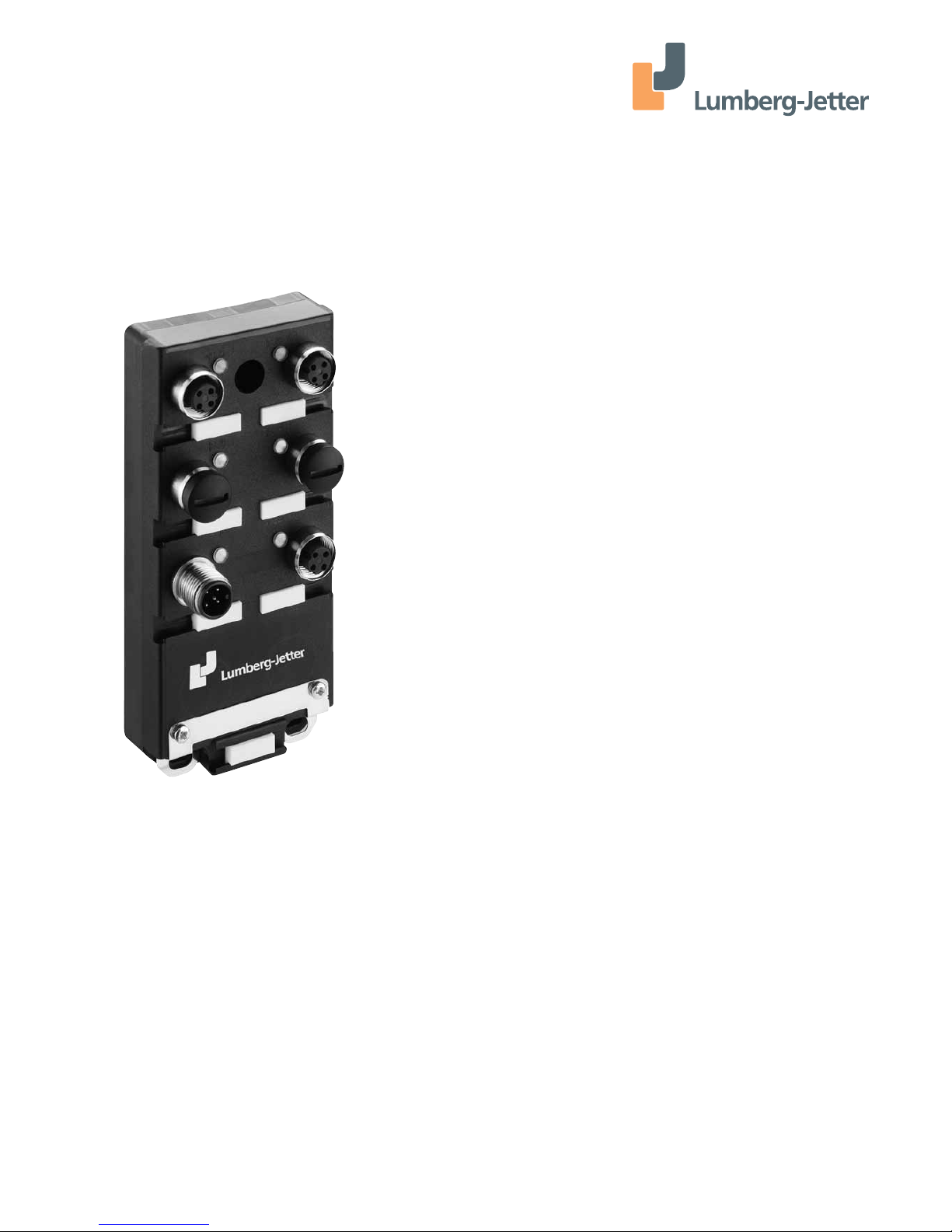
IP67 ETHERNET-Switch
The IP67 Ethernet switch has been especially designed for use in
industrial environments. It supports ETHERNET10 MBit/s and Fast
ETHERNET 100 MBit/s.
The Ethernet switch modules support switched ETHERNET
networks in accordance with IEEE standard 802.3 (10BASE-T) or
802.3u (100BASE-TX) using copper technology.
The switch modules are fitted at the installation site using screws.
The switch modules have five 10/100 Mbit/s twisted pair ports
(10BASET/100BASE-TX, shielded M12 connectors).
It is possible to connect up to five DTEs (data terminal equipment)
or other TP/TX network segments to these ports using twisted
pair cabling.
The TP ports support auto negotiation, autopolarity and
autocrossing.
The IP67 switch conforms with protection class IP67 (protection
against shock and foreign particles: dust proof, water protection:
protected against the effects at temporary immersion in water).
Order No.
0982 EEC 100
Page 2
2
The performance features described here are binding only if they
have been expressly guaranteed in the contract. We have checked
that the contents of the technical publication agree with the
hardware and software described. However, it is not possible to
rule out deviations completely, so we are unable to guarantee
complete agreement. However, the details in the technical publication are checked regularly. Any corrections which prove necessary are contained in subsequent editions. We are grateful for
suggestions for improvement.
We reserve the right to make technical modifications.
Permission is not given for the circulation or reproduction of this
document, its use or the passing on of its contents unless granted
expressly. Contravention renders the perpetrator liable for compensation for damages. All rights reserved, in particular in the
case of patent grant or registration of a utility or design.
Note
We would point out that the content of these operating instructions is not part of, nor is it intended to amend an earlier or existing agreement, permit or legal relationship. All obligations on
Lumberg-Jetter arise from the respective purchasing agreement
which also contains the full warranty conditions which have sole
applicability. These contractual warranty conditions are neither
extended nor restricted by comments in these operating instructions.
We would furthermore point out that for reasons of simplicity, these
operating instructions cannot describe every conceivable problem
associated with the use of this equipment. Should you require further information or should particular problems occur which are not
treated in sufficient detail in the operating instructions, you can
request the necessary information from your local Lumberg-Jetter
sales partner or directly from the Lumberg-Jetter office (address:
refer to chapter entitled „Notes on CE identification“).
Safety Instructions
This manual contains instructions which must be observed to
ensure your own personal safety and to avoid damage to devices
and machinery. The instructions are highlighted with a warning
triangle and are shown as follows according to the degree of
endangerment:
Danger!
means that death, serious injury or considerable damage to
property will result if the appropriate safety measures are
not taken.
Warning!
means that death, serious injury or considerable damage to
property can result if the appropriate safety measures are not
taken.
Caution!
means that light injury or damage to property can result if
the appropriate safety measures are not taken.
Note: is an important piece of information about the product,
how to use the product, or the relevant section of the documentation to which particular attention is to be drawn.
Certified usage
Please observe the following:
Warning!
The device may only be employed for the purposes described
in the catalog and technical description, and only in conjunction with external devices and components recommended or
approved by Lumberg-Jetter. The product can only be operated correctly and safely if it is transported, stored, installed
and assembled properly and correctly. Furthermore, it must
be operated and serviced carefully.
Safety Guidelines
Power Supply
Warning!
The devices may only be connected to the supply voltage
shown on the type plate. The devices are designed for operation with a safety extra-low voltage. Thus, they may only be
connected to the supply voltage connections with PELV circuits or alternatively SELV circuits with the voltage restrictions
in accordance with IEC/EN 60950.
For the case where the module is operated with external
power supply: Use only a safety extra-low voltage in accordance
with IEC 950/EN 60 950/VDE 0805 to power the system.
First of all you connect the ground connection, before you
establish the further connections. When you remove connections,
you disconnect the ground connection last.
Relevant for North America:
The subject unit is to be suppplied by a Class 2 power source complying with the requirements of the National Electrical Code,
table 11(b). If power is redundant supplied (two individual power
sources) the power sources together should comply with the
requirements of the National Electrical Code, table 11 (b).
Relevant for North America:
Use 60/75°C or 75°C copper (CU) wire only.
Safety Guidelines
Shielding Ground
Note: The shielding of the twisted pair wires which can be
connected must be grounded on the plug housing.
Beware of possible short circuits when connecting a cable
section with conductive shielding braiding.
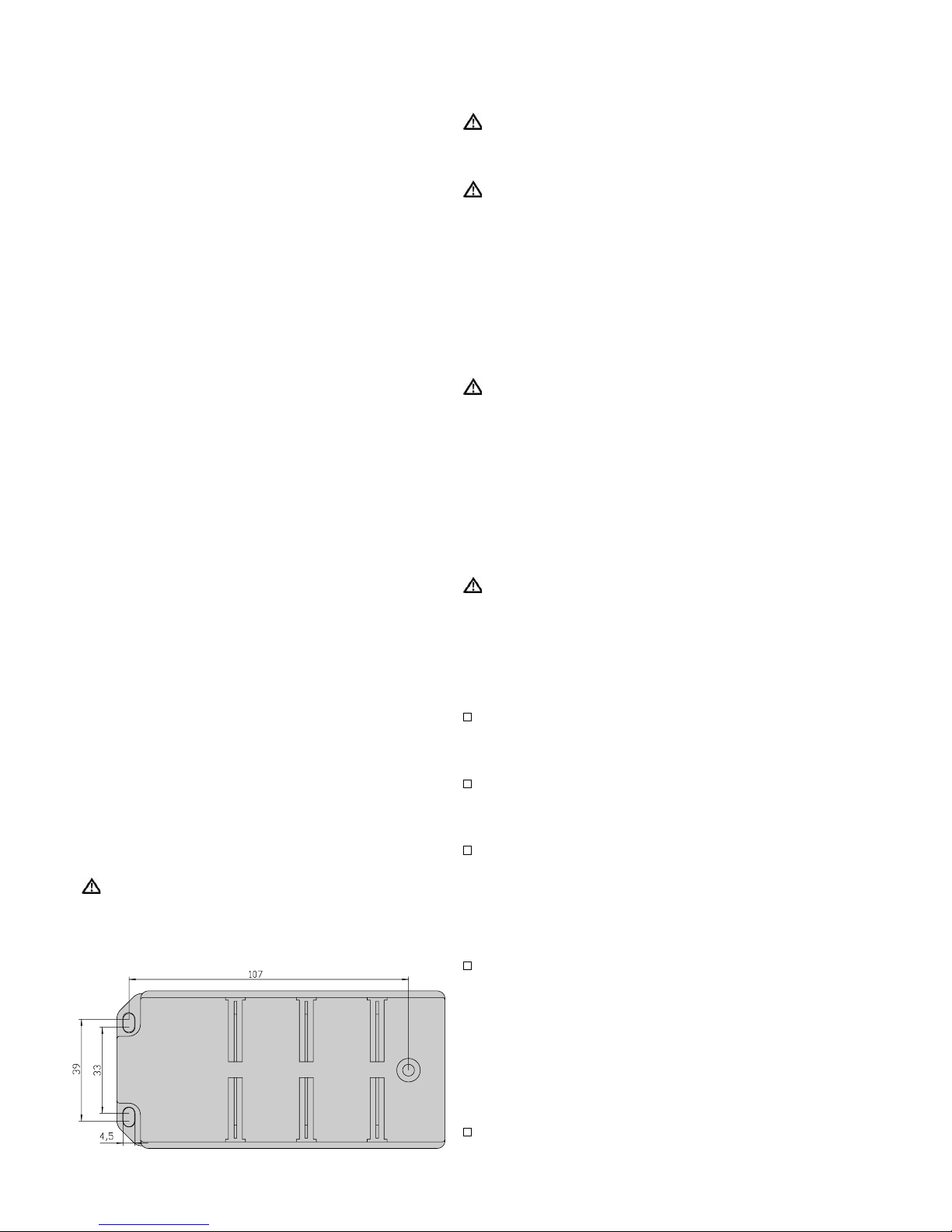
Fig. 1: Drilling jig for assembling the IP 67 switch
Page 3

3
Safety Guidelines Housing
Warning!
Do not try to open the housing of the device.
Make sure that the electrical installation meets local or
nationally applicable safety regulations.
Safety Guidelines Environment
Warning!
The device may only be operated in the listed ambient
temperature range.
The installation location is to be selected so as to ensure compli-
ance with the climatic limits listed in the Technical Data.
Staff qualification requirements
Note: Qualified personnel, as understood in this manual and in
the warning signs, are persons who are familiar with the setup,
assembly, startup, and operation of this product and are appropriately qualified for their job. This includes, for example, those persons who have been:
– trained or directed or authorized to switch on and off, to
ground and to label power circuits and devices or systems in
accordance with current safety engineering standards;
– trained or directed in the care and use of appropriate safety
equipment in accordance with the current standards of safety
engineering;
– trained in providing first aid.
General Safety Instructions
This device is electrically operated. Adhere strictly to the safety
requirements relating to voltages applied to the device as
described in the operating instructions!
Warning!
Failure to observe the information given in the warnings
could result in serious injury and/or major damage.
Only personnel that have received appropriate training
should operate this device or work in its immediate vicinity.
The personnel must be fully familiar with all of the warnings
and maintenance measures in these operating instructions.
Correct transport, storage, and assembly as well as careful
operation and maintenance are essential in ensuring safe and
reliable operation of this device. Use only undamaged parts!
These products are only to be used in the manner indicated in
this version of the ”Description and Operating Instructions”.
Particular attention is to be paid to all warnings and items of
information relating to safety.
Warning!
Any work that may have to be performed on the electrical
installation should be performed by fully qualified technicians
only.
Based specifications and standards
The devices fulfil the following specifications and standards:
– EN 61000-6-2:2001 Generic standards – Immunity for industrial
environments
– EN 55022:1998 + A1 2000 – Information technology
equipment – Radio disturbance characteristics
– EN 60950:1997 – Safety of Information
Technology Equipment (ITE)
– EN 61131-2:1994 + A12 2000 – Programmable Controllers
– FCC 47 CFR Part 15:2000 – Code of Federal Regulations
– cUL 508:1998 – Underwriters Labratories Inc.
Safety for Industrial Control Equipment.
Certified devices are marked with a certification identifier.
Notes on CE identification
The devices comply with the regulations of the following
European directive:
89/336/EEC: Council Directive on the harmonization of the
legal regulations of member states on electromagnetic compatibility (amended by Directives 91/263/EEC, 92/31/EEC and
93/68/EEC). The EU declaration of conformity is kept available
for the responsible authorities in accordance with the abovementioned EU directives at:
Lumberg-Jetter GmbH & Co. KG, 58579 Schalksmühle
Tel. ++49 (0)2355 / 83-5 85
The product can be used in the industrial sphere and in the
residential sphere (residential sphere, business and trade
sphere and small companies).
– Interference immunity: EN 61000-6-2:2001
– Radio interference level: EN 55022:1998 + A1 2000 Class A
Warning!
This is a Class A device. This equipment may cause radio interference if used in a residential area; in this case it is the operator´s responsibility to take appropriate measures.
The precondition for compliance with EMC limit values is
strict adherence to the construction guidelines specified in
this description and operating instructions.
FCC Note:
This equipment has been tested and found to comply with the
limits for a Class A digital device, persuant to part 15 of the FCC
Rules. These limits are designed to provide reasonable protection
against harmful interference when the equipment is operated in
a commercial environment. This equipment generates, uses, and
can radiate radio frequency energy and, if not installed and used
in accordance with the instruction manual, may cause harmful
interference to radio communications. Operation of this equipment in a residential area is likely to cause harmful interference
in which case the user will be required to correct the interference
at his own expense.
Recycling Note:
After its use, this product has to be processed as electronic scrap
and disposed of according to the prevailing waste disposal regulations of your community / district / country / state.
Page 4
4
1. Functional description
The 10/100BASE-T(X) ports of the switch represent a terminal
connection for the connected LAN segment. You can connect
single devices or complete network segments.
1.1 FRAME SWITCHING FUNCTIONS
Store and Forward
All data received by the switch from the system bus or at the
ports are stored and checked for validity. Invalid and defective
frames (> 1.522 byte or CRC error) as well as fragments (< 64 byte)
are discarded. The switch forwards the valid frames.
Multi address capability
The switch learns all source addresses per port. Only packets with
– unknown addresses
– addresses learnt at this port
– a multi/broadcast address
in the destination address field are sent to this port.
The switch learns up to 1000 addresses. This becomes necessary if
more than one terminal device is connected to one or more ports.
In this way several independent subnetworks can be connected to
the switch.
Learnt addresses
The switch monitors the age of the learned addresses. The switch
deletes address entries from the address table which exceed a
certain age (300 seconds).
Note: Restarting deletes the learned address entries.
Tagging (IEEE 802.1Q)
The IEEE 802.1 Q standard designates the VLAN tag to be included in a MAC data frame for the VLAN and prioritizing functions.
The VLAN tag consists of 4 bytes (2 bytes tag protocol identifier
TPID, 2 bytes tag control information TCI). It is inserted between
the source address field and the type field. Data packets with
VLAN tag are transmitted unchanged by the switch.
1.2 SPECIFIC FUNCTIONS OF THE TP/TX INTERFACE
Link control
The switch monitors the connected TP line segments for short-circuit or interrupt using regular link test pulses in accordance with
IEEE standard 802.3 10BASE-T/-100BASETX. The switch does not
transmit any data to a TP segment from which it does not receive
a link test pulse.
Note: A non-occupied interface is assessed as a line interrupt. The
TP line to terminal equipment which is switched off is likewise
assessed as a line interrupt as the deenergised bus coupler cannot
transmit link test pulses.
Auto polarity exchange
If the receive line pair is incorrectly connected (RD+ and RDswitched) polarity is automatically reversed.
Autonegotiation
Autonegotiation is a procedure in which the switch automatically
selects the operating mode of its 10/100 M12 ports. When a connection is set up for the first time, the switch detects the speed
(10 or 100 Mbit/s) and the transmission mode of the connected
network (half duplex or full duplex).
Autocrossing
The switch detects the transmit and receive pairs (MDI, MDI-X).
The switch automatically configures its port for the correct transmit and receive pins. Consequently it does not matter whether
you connect devices using a cross-over or straight cable.
1.3 FURTHER FUNCTIONS AND FEATURES
Reset
The switch will be reset by the following action:
– input voltages fall below a threshold
After a reset the following action is carried through:
– initialization
1.4 DISPLAY ELEMENTS
Equipment status
These LEDs provide information about statuses which affect the
function of the entire switch.
PWR – Power
– lit green: – supply voltage present
Port status
These LEDs display port-related information
LNK/ACT 1 to 5 – Data, Link status
– not lit: – no valid link
– lit green: – valid link
– flashes green: – receiving data
1.5 INTERFACES
10/100 Mbit/s connection (TP port)
M12 socket (4-pin)
Five 10/100 Mbit/s ports (4-pin shielded M12 socket with D coding)
allow the connection of data terminal equipment or independent
network segments conforming to the IEEE 802.3 100BASE-TX /
10BASE-T standard. These ports support auto negotiation and the
auto polarity function. The shielding of the twisted pair wires
which can be connected must be grounded on the plug housing
of the M12 connector.
Pin configuration of the M12 socket:
– Pin 1: TD+ Transmit Data +
– Pin 2: RD+ Receive Data +
– Pin 3: TD- Transmit Data – Pin 4: RD- Receive Data – housing: shield
Power supply connector
M12 connector (5-pin)
The power for the switch is supplied via a 5-pin M12
connector (A coding). Typically, the supply voltage is +24V DC. It is
electrically isolated from the function ground.
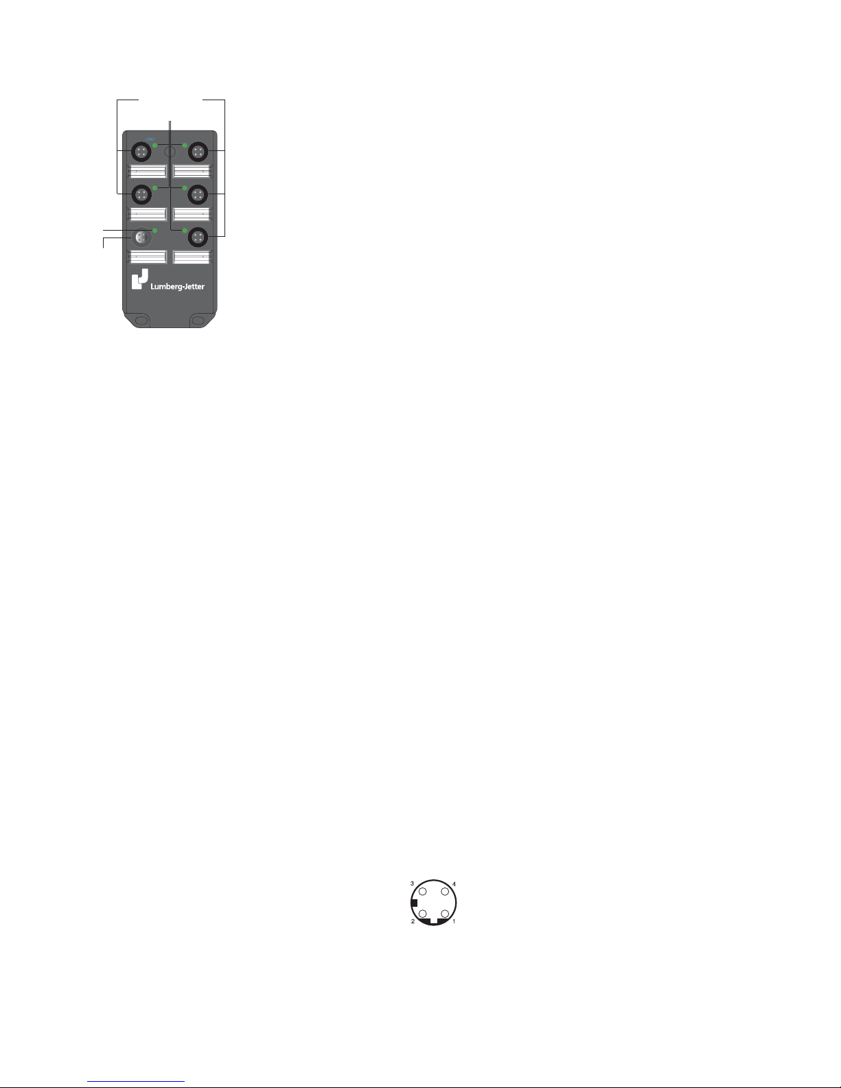
LNK/ACT LNK/ACT
LNK/ACT LNK/ACT
PWR
LNK/ACT
five 4 pin M12 sockets
(Twisted Pair Ports 1 to 5)
5 pin M12 connector
(power supply
connection)
LED display
Power
LED displays
per port
Fig. 2: Overview display elements and interfaces of the IP67 switch
Fig. 3: Pin configuration of an
TP/TX interface (M12 socket)
Page 5
Pin assignment of the M12 connector:
– pin 1: input voltage +
– pin 2: not assigned
– pin 3: input voltage – pin 4: not assigned
– pin 5: function ground
Warning!
The switch devices are designed for operation with a safety
extra-low voltage. Thus, they may only be connected to the
supply voltage connections with PELV circuits or alternatively
SELV circuits with the voltage restrictions in accordance with
IEC/EN 60950.
Voltage supply: The supply voltage is electrically isolated from
the housing.
Ground
The device is grounded via the fixing screws of the chassis or via
the pin 5 of the power supply connector. The grounding via the fixing screws is to be prefered.
2. Configuration
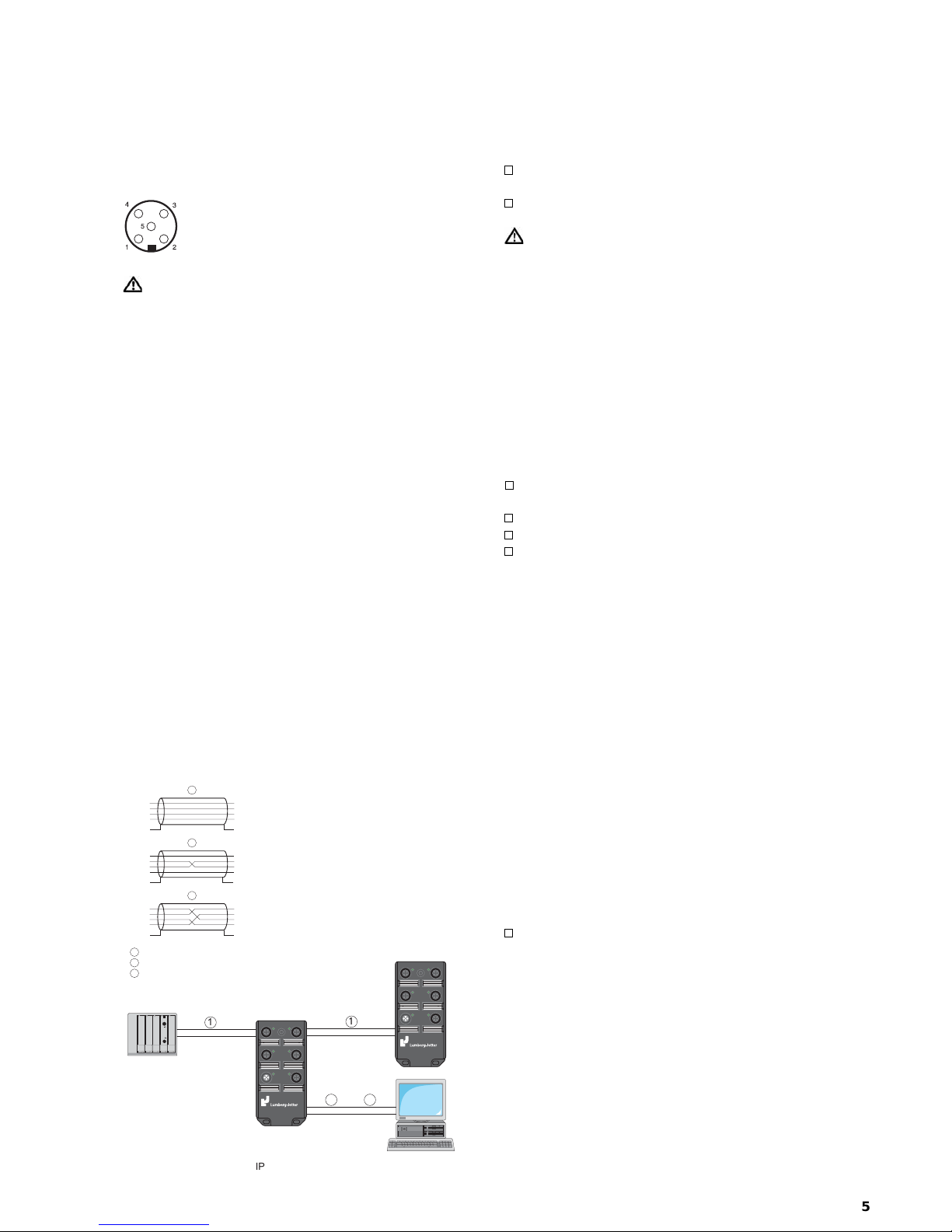
2.1 CONNECTING DTE AND OTHER NETWORK SEGMENTS
It is possible to connect up to five data terminal equipment (DTE)
or other network segments to the 10/100 Mbit/s ports of the
switch using twisted pair cabling (ref. Fig. 5).
2.2 PATCH CABLES
To operate the IP 67 switch, use patch cables
as shown in Figs. 5 and 6.
Notes:
– Use a shielded CAT5 cable.
– Use a shielded 4-pin M12 connector.
– Connect the cable shield to the connector housing.
– You only need one M12-M12 patch cable version.
3. Assembly, startup procedure and dismantling
3.1 UNPACKING, CHECKING
Check whether the package was delivered complete
(see scope of delivery).
Check the individual parts for transport damage.
Warning!
Use only undamaged parts!
3.2 ASSEMBLY
The equipment is delivered in a ready-to-operate condition.
To protect the exposed contacts of the components still to be
installed from dirt, the individual system components must be
connected in a dry and clean area.
Ports which are not assigned are to be closed with the covering
caps contained in the scope of delivery.
Note: Connectors are not electrical isolating devices. Therefore,
first plug the connector to the power supply plug and then switch
on the power supply.
The following sequence is the best for assembly:
drill holes at the installation site
Prepare assembly at the installation site:
drill holes at the installation site
Mechanical assembly at the installation site
Electrical connection with peripheral devices
Connect the signal lines with the twisted pair ports
Assembly:
– Fit the module on a level surface with three M4x16 screws.
– Provide a low impedance ground connection via the clips at
the screen plate, either by mounting directly on a conductive
surface or by the additional connection of a ground wire to
a fastening strap on the screen plate. Use toothed locking
washers for a good electrical connection.
A drill hole dimensioning can be found on page 2, Fig. 1.
Connection:
– The protection class IP 67 is only achieved when bolted
together.
– Empty slots must be sealed with the protective caps supplied.
Notes on wiring:
In keeping with the general installation regulations, ensure that
the signal and power lines > 60 V are laid separately (cable duct,
clamps). The signal and 24 V supply voltage lines should be laid
off the module as straight as possible.
Notes on strain relief:
Provide sufficient strain relief and secure cable fastening for all
connected wiring.
3.3 STARTUP PROCEDURE
You start up the IP 67 switch by connecting the supply voltage
via the 5-pin M12 connector.
4. Further support
In the event of technical queries, please talk to the
Lumberg-Jetter contract partner responsible for looking after
your account or directly to the Lumberg-Jetter office. You can
find the addresses of our contract partners
– on the Internet (www.lumberg-jetter.com)
Our support line is also at your disposal:
Tel. +49 (0) 2355 - 83-187 · Fax +49 (0) 23 55 - 83-586
"
!
#
5
1
1
IP67 switch data terminal
device
SPS
LNK/ACT LNK/ACT
LNK/ACT LNK/ACT
PWR
LNK/ACT
LNK/ACT LNK/ACT
LNK/ACT LNK/ACT
PWR
LNK/ACT
2 or
3
Fig. 4: Pin assignment of the M12 connector
(power supply connector)
TX+
RX+
TXRX-
shield
M12
1
2
3
4
S
TX+
RX+
TXRX-
shield
M12
1
2
3
4
S
RX+
RXTX+
TX-
shield
RJ45, MDI-X
1
2
3
6
S
TX+
RX+
TXRX-
shield
M12
1
2
3
4
S
TX+
TXRX+
RX-
shield
RJ45, MDI
1
2
3
6
S
TX+
RX+
TXRX-
shield
M12
1
2
3
4
S
3
2
1
1
connection M12 <-> M12
connection M12 <-> RJ45, MDI-X
connection M12 <-> RJ45, MDI
2
3
Fig. 6: Patch cables for operating the
IP 67 switch
Fig. 5: Possible network
configuration with the
IP67 switch
Page 6
5. Technical data
General data
Operating voltage NEC Class 2 power source 24 VDC (-25% +33%)
safety extra-low voltage (SELV/PELV)
5 A maximum
Buffer time min. 10 ms at 24 VDC
Potential difference between input Potential difference to input voltage, +24 VDC: 32 V DC
voltage and housing Potential difference to input voltage, ground: -32 V DC
Current consumption at 24 V DC 2.4 W max.
Dimensions W x H x D 60 mm x 126 mm x 31 mm
Weight 210 g
Ambient temperature 0 ºC to + 60 ºC
Storage temperature - 25 ºC to + 70 ºC
Atmospheric pressure min. 79 kPa
Protection type IP 67, according to EN 60529
Protection against shock and foreign particles Full shock protection, impenetrable to dust
Water protection Protected against water penetration, during submersion under
specified pressure and time conditions
Interference proof
Discharge of static electricity
– Contact discharge EN 61000-4-2 Test level 2
– Air discharge EN 61000-4-2 Test level 3
Electromagnetic fields EN 61000-4-3 Test level 3
Fast transients EN 61000-4-4 Test level 3
Surge voltage symmetrical EN 61000-4-5 Test level 2
Surge voltage asymmetrical EN 61000-4-5 Test level 3
Cable-based RF faults EN 61000-4-6 Test level 3
EMC emitted immunity
EN 55022 Class A
FCC 47 CFR Part 15 Class A
Stability
Vibration IEC 60068-2-6 Test FC, testing level in line with IEC 61131-2 E2 CDV
Shock IEC 60068-2-27 Test Ea, testing level in line with IEC 61131-2 E2 CDV
Certifications
UL 508 / C22.2 No.14-M95 pending
Network size
TP-Port 10BASE-T/100BASE-TX
Length of a twisted pair segment 100 m (328 ft) maximum
Interfaces
5 TP ports M12 sockets (4-pin, D coding), 10/100 MBit/s
Displays
Equipment status 1 x green LED PWR – power, supply voltage present
Port status 5 x green LEDs LNK/ACT – data, link status
Scope of delivery
IP 67 Switch covers for sealing unused ports
labels, description and operating instructions
Order number 0982 EEC 100
Product designation LJN-EEC-100-SW5
Im Gewerbepark 2
58579 Schalksmühle
GERMANY
Tel. +49 (0)2355-83-585
Fax +49 (0)23 55- 83-589
E-Mail
[email protected]
www.lumberg-jetter.com
Lumberg-Jetter GmbH & Co. KG
Printed in Germany · Subject to alterations / Version 1.0 / 05-2004
 Loading...