

Page 1
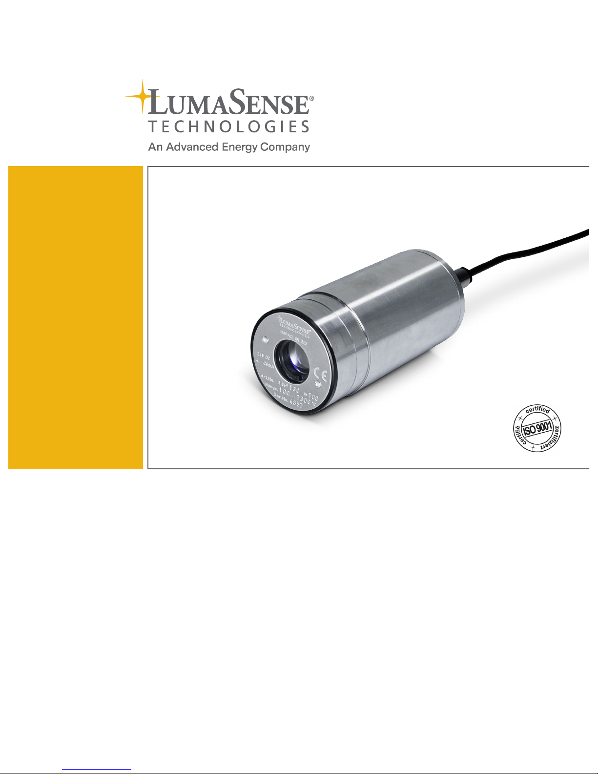
Series 5
IN 5/5 IMPAC Pyrometer
MANUAL
Page 2

Confidential Information
The material contained herein consists of information that is the property of LumaSense
Technologies, an Advanced Energy Company, and intended solely for use by the purchaser of
the equipment described in this manual.
All specifications are subject to change without notice. Changes are made periodically to the
information in this publication, and these changes will be incorporated in new editions.
LumaSense Technologies prohibits the duplication of any portion of this manual or the use
thereof for any purpose other than the operation or maintenance of the equipment described
in this manual, without the express written permission of LumaSense Technologies or Advanced
Energy Industries, Inc.
Any unauthorized use of this manual or its contents is strictly prohibited.
Copyright
© 2019 LumaSense Technologies, Inc. All Rights Reserved. LumaSense Technologies, Inc., a
subsidiary of Advanced Energy Industries, Inc.
Trademarks
IMPAC is a trademark of LumaSense Technologies.
All other trademarks are trademarks, registered trademarks, and/or service marks of their
respective holders.
Service Centers
LumaSense Technologies, Inc.
North America
Sales & Service
Santa Clara, CA, USA
Ph: +1 800 631 0176
Ph: +1 408 727 1600
Fax: +1 408 727 1677
LumaSense Technologies GmbH
Other Than North America
Sales & Support
Frankfurt, Germany
Ph: +49 (0) 69 97373 0
Fax: +49 (0) 69 97373 167
Global and Regional Centers
Our Headquarters
LumaSense Technologies, Inc.
Santa Clara, CA, USA
Ph: +1 800 631 0176
Fax: +1 408 727 1677
Americas, Australia, & Other Asia
LumaSense Technologies, Inc.
Santa Clara, CA, USA
Ph: +1 800 631 0176
Fax: +1 408 727 1677
Europe, Middle East, Africa
LumaSense Technologies GmbH
Frankfurt, Germany
Ph: +49 (0) 69 97373 0
Fax: +49 (0) 69 97373 167
France
LumaSense Technologies Sarl
Erstein, France
Ph: +33 3 8898 9801
Fax: +33 3 8898 9732
India
LumaSense Technologies, India
Mumbai, India
Ph: +
91 22 67419203
Fax: + 91 22 67419201
China
LumaSense Technologies, China
Shanghai, China
Ph: +86 133 1182 7766
Ph: +86 21 5899 7915
E-mail
info@l umasenseinc.c om
Website
http://www.lumasenseinc.com
Part No 3 869 019
Revision January 2019
Page 3

IN 5/5 Operating Manual Contents • iii
Contents
1 General........................................................................................................................ 5
1.1 Information abou t th e user manual ................................................................... 5
1.1.1 Legend ..................................................................................................... 5
1.1.2 Termi nology.............................................................................................. 5
1.2 Safety .................................................................................................................. 5
1.2.1 Electrical connection .................................................................................. 6
1.3 Limit of liability and warranty ........................................................................... 6
1.4 Unpacking the Instrument .................................................................................. 6
1.5 Service Request, Repair, or Support ................................................................... 7
1.6 Shipments to LumaSense for Repair................................................................... 7
1.7 Tr ansport, pac kaging, st orage ............................................................................ 8
1.8 Disposal / decommissioning................................................................................ 8
2 Introduction ................................................................................................................ 9
2.1 App ro priate use .................................................................................................. 9
2.2 Scope of delivery ................................................................................................ 9
2.3 Technical data ..................................................................................................... 9
2.4 Dimensions........................................................................................................ 11
2.5 Phys ic al User Interfac e ...................................................................................... 11
2.6 Accessories (Op t ion a l)....................................................................................... 12
3 Controls and Connections......................................................................................... 13
3.1 Electrical Installation ........................................................................................ 13
3.2 Pin assignment at the pyrometer ..................................................................... 14
3.3 Op t ics................................................................................................................. 14
3.4 Alignment of the instrumen t............................................................................ 15
4 Settings / Parameter Descriptions ............................................................................ 17
4.1 Factory settings................................................................................................. 17
4.2 Instrument settings........................................................................................... 17
4.3 Emissivity (EMI)................................................................................................. 17
4.4 Response time / exposure time (t90).................................................................. 19
4.5 Avoiding reading errors caused by faulty assembly ........................................ 19
5 Maint enanc e ............................................................................................................. 21
5.1 Safety ................................................................................................................ 21
5.2 Service ............................................................................................................... 21
6 Referenc e nu mb ers ................................................................................................... 23
6.1 Referenc e nu mb ers instrument ........................................................................ 23
6.2 Referenc e nu mb ers access or ies ........................................................................ 23
Page 4

IN 5/5 Operating Manual Contents • iv
7 Troublesho oting........................................................................................................ 25
Index ............................................................................................................................... 27
Page 5
IN 5/5 Operating Manual General • 5
1 General
1.1 Information about the user manual
Congratulations on choosing the high quality and highly efficient IMPAC pyrometer.
This manual provides important information about the instrument and can be used as a work of
reference for installing, operating, and maintaining your IMPAC pyrometer. It is important that
you carefully read the information contained in this manual and follow all safety procedures
before you install or operate the instrument.
To avoid handling errors, keep this manual in a location where it will be readily accessible.
1.1.1 Legend
Note: The note symbol indicates tips and useful information in this manual. All notes
should be read to effectively operate the instrument.
Warnings and Cautions: The general warnings and cautions symbol signifies the
potential for bodily harm or damage to equipment.
MB Shortcut for Temperature range (in German: Messbereich).
1.1.2 Terminology
The terminology used in this manual corresponds to the VDI- / VDE-directives 3511, Part 4.
1.2 Safety
This manual provides important information on safely installing and operating the IMPAC
pyrometer. Several sections of this manual provide safety warnings to avert danger. These safety
warnings are specified with a warning symbol. You must read and understand the contents of
this manual before operating the instrument even if you have used similar instruments or have
already been trained by the manufacturer.
It is also important to continually pay attention to all labels and markings on the instrument and
to keep the labels and markings in a permanent readable condition.
Warning: The pyrometer is only to be used as described in this manual. It is
recommended that you only use accessories provided by the manufacturer.
In addition, signs and markings on the device are to be observed and maintained in legible
condition.
Page 6

IN 5/5 Operating Manual General • 6
1.2.1 Electrical connection
Follow common safety regulations for mains voltage (e.g. 230 or 115 V AC) connecting
additional devices operating with this mains voltage (e.g. transformers). Touching mains voltage
can be mortal. A non-expert connection and mounting can cause serious health or material
damages.
Only qualified specialists are allowed to connect such devices to the mains voltage.
1.3 Limit of liability and warranty
All general information and notes for handling, maintenance, and cleaning of this instrument
are offered according to the best of our knowledge and experience.
LumaSense Technologies is not liable for any damages that arise from the use of any examples
or processes mentioned in this manual or in case the content of this document should be
incomplete or incorrect. LumaSense Technologies reserves the right to revise this document and
to make changes from time to time in the content hereof without obligation to notify any
person or persons of such revisions or changes.
All instruments from LumaSense Technologies have a regionally effective warranty period.
Please check our website at http://info.lumasenseinc.com/warranty
for up-to-date warranty
information. This warranty covers manufacturing defects and faults, which arise during
operation, only if they are the result of defects caused by LumaSense Technologies.
The warranty is VOID if the instrument is disassembled, tampered with, altered, or otherwise
damaged without prior written consent from LumaSense Technologies; or if considered by
LumaSense Technologies to be abused or used in abnormal conditions. There are no userserviceable components in the instrument.
1.4 Unpacking the Instrument
Thoroughly inspect the instrument upon delivery to purchaser. Check all materials in the
container against the enclosed packing list. LumaSense Technologies cannot be responsible for
shortages against the packing list unless a claim is immediately filed with the carrier. The
customer must complete final claim and negotiations with the carrier.
Save all packing materials, including the carrier’s identification codes, until you have inspected
the pyrometer and find that there is no obvious or hidden damage. Before shipment, the
pyrometer was examined and has been tested. If you note any damage or suspect damage,
immediately contact the carrier and LumaSense Technologies, Inc.
Page 7

IN 5/5 Operating Manual General • 7
1.5 Service Request, Repair, or Support
Contact LumaSense Technologies Technical Support in case of a malfunction or service request.
Provide clearly stated details of the problem as well as the instrument model number and serial
number. Upon receipt of this information, Technical Support will attempt to locate the fault
and, if possible, solve the problem over the telephone.
If Technical Support concludes that the instrument must be returned to LumaSense Technologies
for repair, they will issue a Return Material Authorization (RMA) number.
Return the instrument upon receipt of the RMA number, transportation prepaid. Clearly
indicate the assigned RMA number on the shipping package exterior. Refer to Section 1.6,
Ship ments t o LumaSens e f o r Rep air, for shipping instructions.
Technical Support can be contacted by telephone or email:
Santa Clara, California
• Telephone: +1 408 727 1600 or +1 800 631 0176
• Email: [email protected]
Frankfurt, Germany
• Telephone: +49 (0) 69 97373 0
• Email: [email protected]
Erstein, France
• Telephone +33 (0)3 88 98 98 01
• Email: [email protected]
1.6 Shipments to LumaSense for Repair
All RMA shipments of LumaSense Technologies instruments are to be prepaid and insured by
way of United Parcel Service (UPS) or preferred choice. For overseas customers, ship units airfreight, priority one.
The instrument must be shipped in the original packing container or its equivalent. LumaSense
Technologies is not responsible for freight damage to instruments that are improperly packed.
Contact us to obtain an RMA number (if Technical Support has not already assigned one).
Clearly indicate the assigned RMA number on the shipping package exterior.
Send RMA Shipments to your nearest technical service center:
Customers in No rth Americ a
should send RMA Shipments to:
Santa Clara, California
All other customers should
send RMA Shipments to:
Frankfurt, Germany
LumaSense Technologies, Inc.
3301 Leonard Court
Santa Clara, CA 95054 USA
Telephone: +1 408 727 1600
+1 800 631 0176
Email: [email protected]
LumaSense Technologies GmbH
Kleyerstr. 90
60326 Frankfurt
Germany
Telephone: +49 (0)69-97373 0
Email: [email protected]
Page 8

IN 5/5 Operating Manual General • 8
1.7 Transport, packaging, storage
With faulty shipping, the instrument can be damaged or destroyed. To transport or store the
instrument, please use the original box or a box padded with sufficient shock-absorbing
material. For storage in humid areas or shipment overseas, the device should be placed in
welded foil (ideally along with silica gel) to protect it from humidity.
The pyrometer is designed for a storage temperature of -20 to 70 °C with non-condensing
conditions. Storing the insturment out of these conditions can cause damage or result in
malfunction of the pyrometer.
1.8 Disposal / decommissioning
Inoperable IMPAC pyrometers mus t be disposed of in compliance with local regulations for
electro or electronic material.
Page 9
IN 5/5 Operating Manual Introduc tion • 9
2 Introduction
2.1 Appropriate use
The IN 5/5 is a stationary infrared thermometer for non-contact temperature measurement of
glass and quartz glass surfaces with temperature ranges between 100 and 2500 °C.
For optimal match of the instrument to the application the pyrometers are equipped ex works
with the desired optics (for every instrument 3 different optics are available).
2.2 Scope of delivery
Instrument with selected optic, works certificate, operation manual.
Note: The connection cable is not included with the instrument and mu st be ordered
separately (see section 7, Reference numbers).
2.3 Technical data
Temperature Ranges:
100 ... 600 °C (MB 6)
200 ... 800 °C (MB 8)
100 ... 1300 °C (MB 13)
400 ... 2500 °C (MB 25)
(Further MB on request)
IR Detector:
Thermopile
Data Handling:
Digital
Spectral Range:
5.14 μm
Power Supply:
24 V DC (10 ... 30 V)
Power Consumption:
Max. 20 mA
Load:
Max. 700 Ω @ 24 V (max. 100 Ω @ 12 V)
Response Time t90:
0.08 s; adjustable in the pyrometer: 0.5 s; 1 s; 2 s; 5 s
Analog Output:
4 ... 20 mA (linear)
Parameters:
Adjustable on the pyrometer: Emissivity, Exposure time
Emissivity ε:
0.2 ... 1 adjustable
Measurement
Uncertainty:
Dependent on object
temperature T and
ambient temperature
T
amb
(ε = 1, t90 = 1 s)
T < 1300 °C:
0.6% of reading in °C or 2 °C (T
amb
= 15 ... 30 °C)1
1% of reading in °C or 1.5 °C (T
amb
= 0 ... 15 or 30 ... 63 °C)1
T = 1300 ... 1800 °C:
0.8% of reading in °C (T
amb
= 15 ... 30 °C)
1.2% of reading in °C (T
amb
= 0 ... 15 or 30 ... 63 °C)
T = 1800 ... 2500 °C:
1% of reading in °C (T
amb
= 15 ... 30 °C)
1.4% of reading in °C (T
amb
= 0 ... 15 or 30 ... 63 °C)
Repeatability:
(ε = 1, t90= 1 s)
0.3% of reading in °C or 0.6 °C1
Page 10
IN 5/5 Operating Manual Introduc tion • 10
Noise Equivalent
Temperature Difference
(NETD):
(ε = 1, T
amb
= 23 °C)
@ t90 = 80 ms: 0.7 °C (@ 110 °C measuring temperature)
@ t90 = 1 s: 0.4 °C (@ 110 °C measuring temperature)
Protection Class:
IP65 (DIN 40050)
Ambient
Temperature:
0 ... 70 °C
Storage Temperature:
-20 ... 70 °C
Rel. Humidity:
Non-condensing conditions
Weight:
Approx. 410 g
Housing:
Stainless steel
Operating Position:
Any
Optics:
Zinc-Sulfide lens (ZnS)
CE-label:
According to EU directives about electromagnetic immunity
1
Whichever value is greater. The instrument must be at a const. amb. temp. for min. 15 min. and
has to be connected to the power supply.
Note: The determination of the technical data of this pyrometer is carried out in
accordance with VDI/VDE directive IEC TS 62942-2, “Determination of the technical data
for radiation thermometers”.
The calibration / adjustment of the instruments was carried out in accordance with
VDI/VDE directive “Temperature measurement in industry, Radiation thermometry,
Calibration of radiation thermometers”, VDI/VDE 3511, Part 4.4.
For additional details on this directive, see http://info.lumasenseinc.com/calibration or
order the directive from “Beuth Verlag GmbH” in D-10772 Berlin, Germany.
Page 11
IN 5/5 Operating Manual Introduc tion • 11
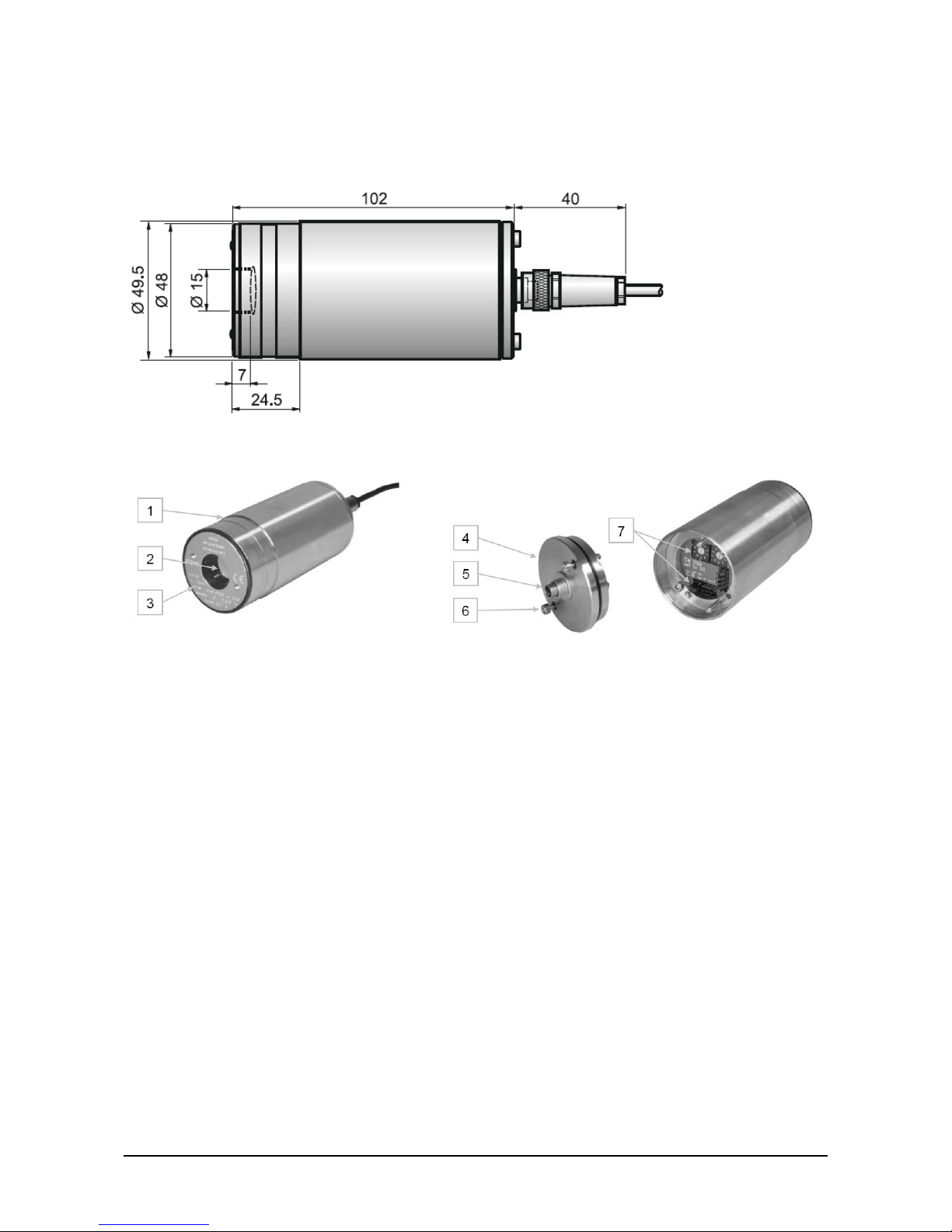
2.4 Dimensions
2.5 Physical User Interface
1 Stainless steel housing
2 Optics
3 Type label
4 Rear panel
5 Electrical connection
6 Fixing screws for rear panel
7 Settings at the pyrometer
Page 12
IN 5/5 Operating Manual Introduc tion • 12
2.6 Accessories (Optional)
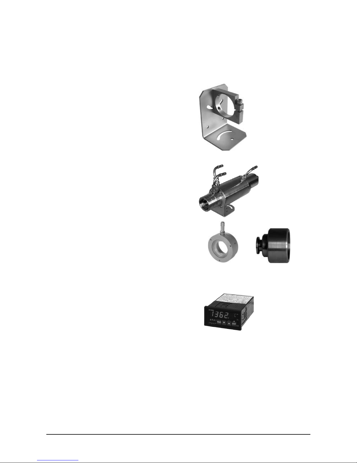
Numerous accessories guarantee easy installation of the pyrometer. The following overview
shows a selection of suitable accessories. You can find the entire accessory program with all
reference numbers in Chapter 7, Refer ence n umbers.
Mounting:
For easy mounting and aligning the pyrometer to
the measured object an adjustable mounting angle is
available.
Mounting angle
Cooling:
The completely covered water cooling jacket made
from stainless steel protects the pyrometer if
exposed to a hot environment. It is designed for
ambient temperatures up to 180 °C.
Water cooling
jacket with
integrated air purge
Miscellaneous:
The air purge protects the lens from contamination
with dust and moisture. It has to be supplied with
dry and oil-free pressurized air and generates an air
stream shaped like a cone.
The pyrometer can be easily fixed on a vacuum
chamber with the KF 16 vacuum support with
sighting window.
Air purge Vacuum support
Display:
For temperature indication of the pyrometer IMPAC
offers several digital displays.
Digital display
DA 6000
Page 13
IN 5/5 Operating Manual Controls and Connecti ons • 13
3 Controls and Connections
3.1 Electrical Installation
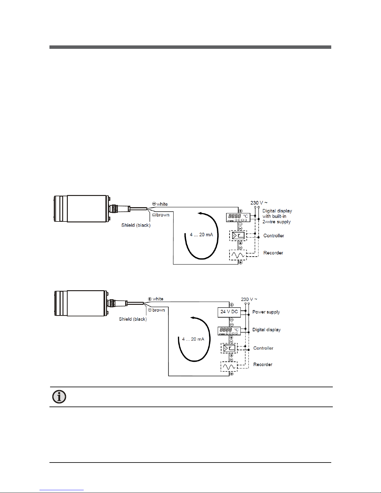
The pyrometers are powered by 24 V DC nominal (possible range: 10 ... 30 V). When connecting
the device to the power supply ensure correct polarity. The power consumption (in this case
4 ... 20 mA) is also the measuring signal. The instrument doesn’t need any time for starting or
preheating and is immediately ready for operation.
To switch off the instrument, interrupt the power supply or unplug the electrical connector.
To meet the electromagnetic requirements (EMV), a shielded connecting cable must be used.
The shield of the connecting cable has to be connected only on the pyrometer’s side. On side of
the power supply (switch board) the shield must be open to avoid ground loops. IMPAC offers
connecting cables, they are not part of standard scope of delivery (see Chapter 7, Reference
Numbers).
Example for wiring using a digital display with integrated power supply:
Example for wiring using an external power supply:
Note: Additional analyzing instruments, e.g. controllers, recorders, etc can be
connected in series as shown in drawing above.
Page 14
IN 5/5 Operating Manual Controls and Connecti ons • 14
3.2 Pin assignment at the pyrometer
3.3 Optics
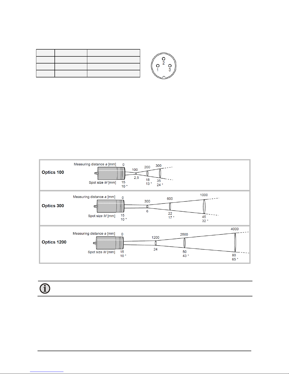
The pyrometers are equipped ex works with one of the following optics. These lenses are
focusing to certain distances. In these distances each lens achieves its smallest spot size. The spot
size will enlarge in any other distance (shorter or longer). Please notice that the measuring
object must be as least as big as the spot size.
The name of the optics (e.g. optics 300) shows the measuring distance in mm (e.g. 300 mm,
measured from the front of the lens) in which it has the smallest spot size (e.g. 6 mm).
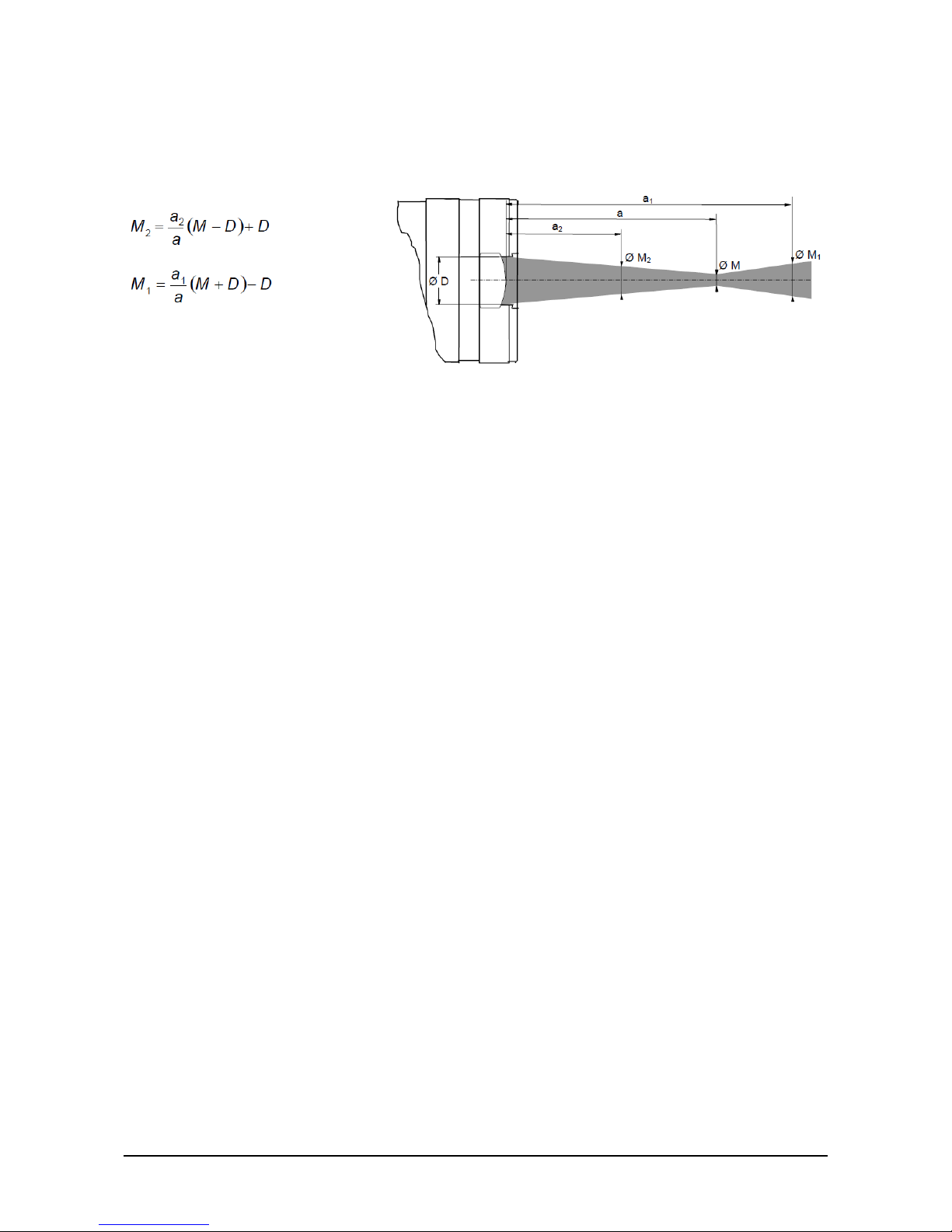
The following drawings show the size of the spots in mm in dependence of the measuring
distance. Values between the mentioned data can be calculated by interpolation. The spot size
for measuring distance 0 is the aperture diameter D of the optics.
*Data based on the IN 5/5, MB 25.
Note: Please note that the optical profiles show nominal dimensions. The spot size
diameter or the focal distance may be slightly different due to lens tolerances.
Pin
Cable Color
Connection
1 white
+24 V DC (10 ... 30 V)
2
brown
0 V
3 black Shield
Instrument’s plug:
3 pin flange connector
Page 15
IN 5/5 Operating Manual Controls and Connecti ons • 15
Spot sizes for intermediate distances, that are not shown on the optical profiles, may be
calculated using the following formula:
3.4 Alignment of the instrument
For exact measurement of the object temperature the pyrometer must be aligned correctly onto
the object. The instruments are not equipped with a sighting so that the aligning must be done
thermally. When measuring a hot object in front of a cooler background, it usually suffices to
align the pyrometer to achieve the highest temperature reading.
Page 16

IN 5/5 Operating Manual Controls and Connecti ons • 16
To ensure consistent document formatting, this page was intentionally left blank.
Page 17
IN 5/5 Operating Manual Settings / Parameter Descriptions • 17
4 Settings / Parameter Descriptions
4.1 Factory settings
Emissivity (EMI) = 100%
Exposure time (t
90
) = 0.08 s
4.2 Instrument settings
The emissivity of the measuring object and the and instrument’s exposure time can be set via
controls in the pyrometer housing.
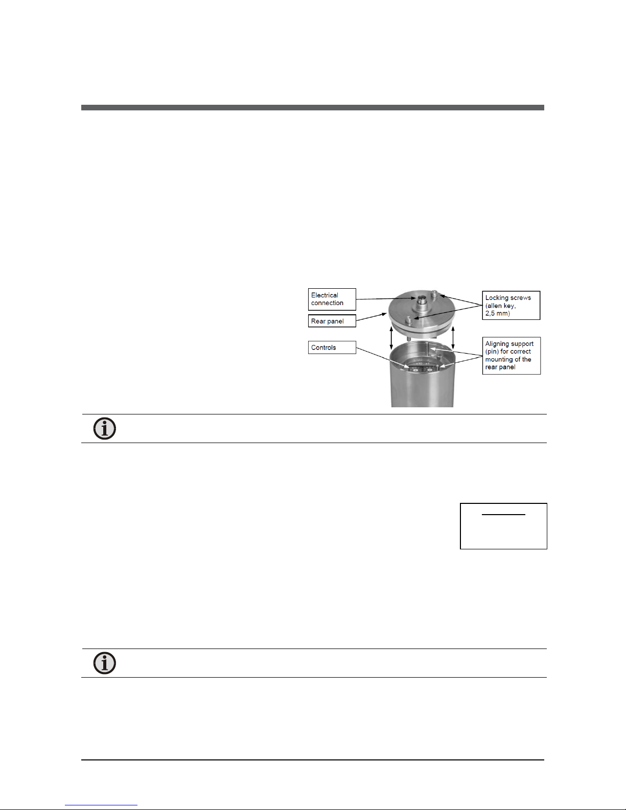
The controls can be accessed by removing
the rear panel in the following way:
1. Disconnect the electrical
connection.
2. Unscrew the rear screws with a
2.5 mm allen screw.
3. Take the cover off, making sure it
remains straight (without bending
or twisting it).
Note: Please make sure that the pyrometer is not contaminated while open.
Assembling: When reassembling the cover, insert it carefully into the guide pins and then fasten
it with the screws. The connector cable can now be plugged in.
4.3 Emissivity (EMI)
For a correct measurement it is necessary to adjust the emissivity. This
emissivity is the relationship between the emission of a real object and the
emission of a black body radiation source (this is an object which absorbs all
incoming rays and has an emissivity of 100%) at the same temperature.
Different materials have different emissivities ranging between 0% and 100% (settings at the
pyrometer between 20 and 100%). Additionally, the emissivity is depending on the surface
condition of the material, the spectral range of the pyrometer and the measuring
temperature. The emissivity setting of the pyrometer has to be adjusted accordingly. Typical
emissivity values of various common materials for the two spectral ranges of the instruments are
listed below. The tolerance of the emissivity values for each material is mainly dependent on the
surface conditions. Rough surfaces have higher emissivities.
Note: The minimum emissivity setting for the pyrometer is 20%!
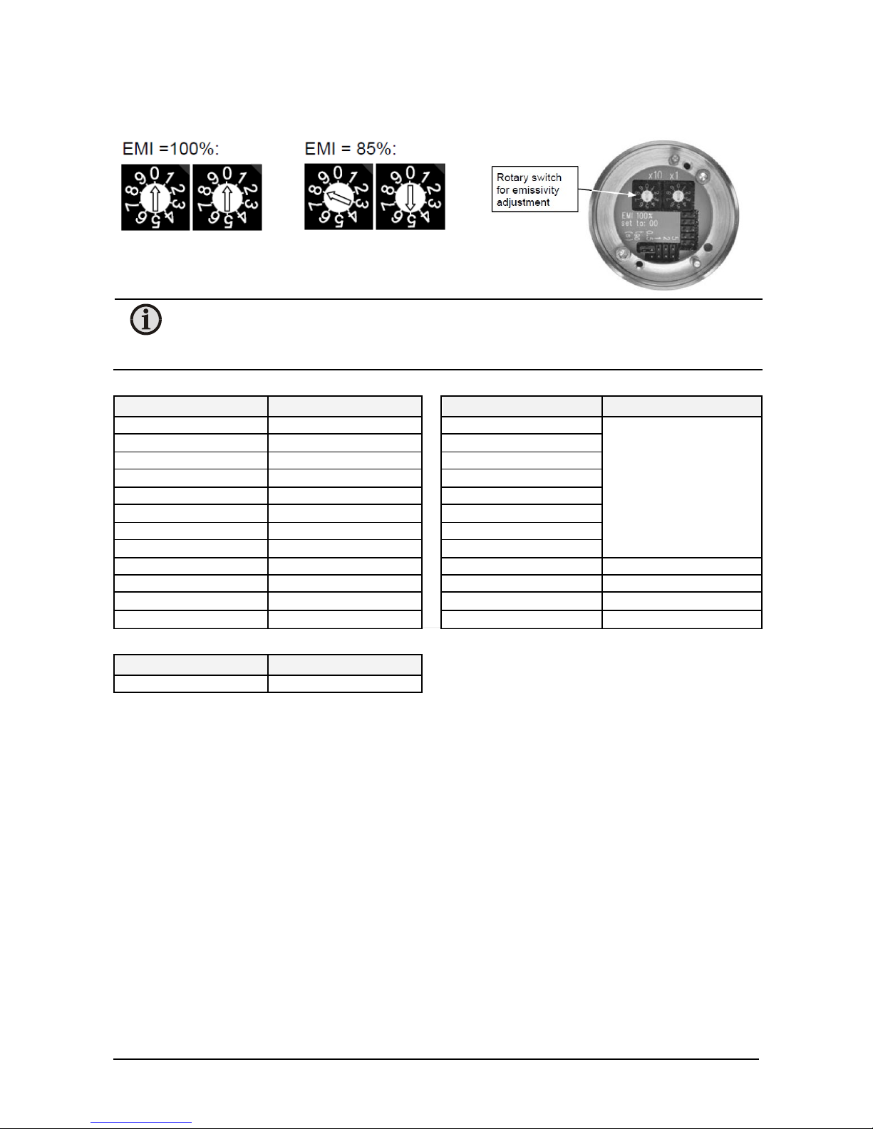
The settings will be done via the rotary switch.
Settings:
100%
.
.
.
20%
Page 18
IN 5/5 Operating Manual Settings / Parameter Descriptions • 18
Setting examples:
Note: If the emissivity is set to an incorrect value (below 20%) the instrument will
automatically utilize an emissivity value of 100%. The setting 00 is interpreted as
EMI = 100%.
Measuring object
EMI (@ 8 ... 14 μm)
Measuring object
EMI (@ 8 ... 14 μm)
“Black body furnace“
100%
Brickwork
85... 95%
Human skin
98%
Fire clay
Black dull varnish
95%
Rubber
Carbon soot
95%
Porcelain
Wood
80 ... 92%
Ceramics
Paper
92 ... 95%
Varnish
Asphalt
85%
Plaster
Glass / quartz glass
72 ... 87%
Oil paint
Textile
75 ... 95%
Steel (oxidized)
60 ... 80%
Graphite
75 ... 92%
Steel (smooth)
10 ... 30%
Cement
90%
Aluminum (smooth)
2 ... 15%
Water
95%
Aluminum (anodized)
90%
Measuring object
EMI (@ 5.14 μm)
Glass / quartz glass
97%
One way to determine an accurate emissivity value for a material is to make a comparison
measurement as follows: If possible, coat a portion of the object with dull black paint or carbon
soot. Paint and carbon soot have high emissivities (95%) and take on the same temperature as
the object. Measure the temperature of the painted area with the emissivity control set to 95%.
Then measure the temperature of an adjacent unpainted area of the object and adjust the
emissivity until the pyrometer displays the same temperature.
Page 19
IN 5/5 Operating Manual Settings / Parameter Descriptions • 19
4.4 Response time / exposure time (t90)
The exposure time t90 is the time interval from the start of measurement up to the respective
change in the output signal (4 ... 20 mA) which is the time taken to reach 90% of the recorded
temperature difference.
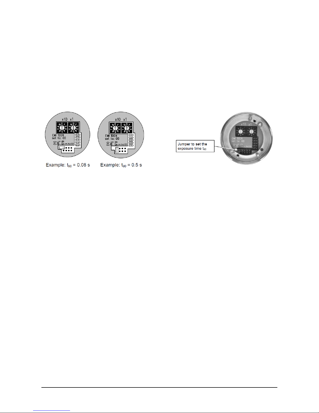
The exposure time is changed by adjusting the jumper position. In the open position shown in
the diagram on the left, the response time is 0.08 s.
For alternative settings (t
90
= 0.5 s, 1 s, 2 s or 5 s) select the respective jumper position.
Longer exposure times are useful when measuring objects with fluctuating temperatures.
4.5 Avoiding reading errors caused by faulty assembly
To avoid reading errors, please note the following points when mounting the pyrometer:
1. The diameter of the measuring object cannot be smaller than the pyrometer’s spot size
(see section 3.3, Optics).
2. A source of radiation behind or around the measuring object can influence the result. If
the object is transparent or partly transparent another material behind the object could
transmit its radiation to the pyrometer as well. In this case the location of the pyrometer
should be changed, or, if the background radiation remains constant it can be
compensated for by changing the emissivity setting respectively.
3. Please take into account that radiation, from other hot materials around the measured
object, can be reflected by these materials and influence the result. If the measured
object has a low emissivity, the temperature measured will be mainly that from the
reflected object - not from the intended measured object itself. To prevent ambient
radiation from reaching the spot area, a mounting tube should be used.
The mounting tube should be placed as near as possible to the measured object so that
the tube’s shadow blocks out all the ambient radiation from the side.
Page 20

IN 5/5 Operating Manual Settings / Parameter Descriptions • 20
To ensure consistent document formatting, this page was intentionally left blank.
Page 21

IN 5/5 Operating Manual Maintenance • 21
5 Maintenance
5.1 Safety
Attention during pyrometer services: Should the pyrometer be integrated in a
running machine process the machine has to be switched off and secured against
restart before servicing the pyrometer.
5.2 Service
The pyrometer does not have any parts which require regular service, only the lens has to be
kept clean. The lens can be cleaned with a soft cloth in combination with alcohol (do not use
acid solutions or dilution).
Also, standard cloths for cleaning glasses or photo objectives can be used.
Page 22

IN 5/5 Operating Manual Maintenance • 22
To ensure consistent document formatting, this page was intentionally left blank.
Page 23

IN 5/5 Operating Manual Reference numbers • 23
6 Reference numbers
6.1 Reference numbers instrument
Type
Optics
Temperature Range1
Reference Number
IN 5/5
When ordering please select one
optics (optics a = 100, 300, or 1200)
100 ... 600 °C
3 869 110
200 ... 800 °C
3 869 120
100 ... 1300 °C
3 869 130
400 ... 2500 °C
3 869 140
1
Other temperature ranges on request.
Scope of delivery: Instrument with selected optic, works certificate, operation manual.
Ordering details: A connection cable is not included with the instrument and has to be
ordered separately.
6.2 Reference numbers accessories
3 820 ... Connection cable for IN 5/5:
2 m
5 m
10 m
15 m
30 m
... 210
... 560
... 570
... 580
... 590
3 852 290 Power supply NG DC (100 ... 240 V AC ⇒ 24 V DC, 1 A)
3 852 540 Power supply NG 0D (85 ... 265 V AC => 24 V DC, 600 mA)
3 890 650 DA 4000: LED digital display, 2 limit switches, 230 V AC
3 891 220 DA 4000: LED digital display, 2 limit switches, 115 V AC
3 890 520 DA 6000: LED digital display, digital and analog input, 2 limit switches, maximum
value storage, analog output, RS232
3 890 530 DA 6000 with RS485
3 826 510 PI 6000: programmable PID controller
3 834 210 Adjustable mounting support
3 835 160 Air purge unit
3 835 440 Air purge unit, stainless steel
3 837 230 Water cooling jacket (heavy design) with integrated air purge unit (metric
mounting threads)
5 837 230 (Same with UNC mounting threads)
3 837 340 Heavy water cooling jacket with protection window
3 837 370 Water cooling jacket (lightweight design) with integrated air purge unit (metric
mounting threads)
5 837 370 (Same with UNC mounting threads)
3 837 390 Lightweight water cooling jacket with protection window
3 846 100 Mounting tube
3 846 120 Flange tube
3 837 540 Cooling plate for series 5 and 6, with air purge
3 846 620 Vacuum flange KF16 with protection window
3 846 650 Spare protection window, Ø 25 x 3 with Viton-O-ri ng
Page 24

IN 5/5 Operating Manual Reference numbers • 24
To ensure consistent document formatting, this page was intentionally left blank.
Page 25

IN 5/5 Operating Manual Troubl eshooting • 25
7 Troubleshooting
Before sending the pyrometer for repair, try to find the error and to solve the problem with th e
help of the following list.
Temperature indication too low
• Incorrect alignment of the pyrometer to the object.
⇒ New correct alignment to achieve the max. temperature signal (see 3.4).
• Measuring object smaller than spot size.
⇒ Check measuring distance, smallest spot size is at nominal measuring distance (see 3.3).
• Emissivity set too high.
⇒ Set lower correct emissivity slope corresponding to the material (see 4.3).
• Lens contaminated
⇒ Clean lens carefully (see 6.2)
Temperature indication too high
• Emissivity slope set too low.
⇒ Set lower correct emissivity slope corresponding to the material (see 4.3).
• The measurement is influenced by reflections of hot machine parts.
⇒ Use mechanical construction to avoid the influence of the interfering radiation.
Measuring errors
• Indicated temperature is decreasing during the use of the pyrometer, contamination of the
lens.
⇒ Clean lens. Recommendation: use of air purge (see 2.6, 6.2).
• Indicated temperature is decreasing during the use of the pyrometer, although the air purge
unit is used. Probably compressed air is not clean or air failed.
⇒ Clean the lens and use clean, dry and oil free compressed air.
• Air contamination in the sighting path between pyrometer and object
⇒ Change position of the pyrometer with a clean sighting path (if necessary use a ratio
pyrometer).
• HF-interferences.
⇒ Correct the connection of the cable shield (see 3.1).
• Instrument overheated
⇒ Use cooling jacket with air or water cooling (see 2.6).
• Temperature Indication is fluctuating, probably caused by changing emissivity
⇒ Wrong pyrometer type, use of ratio pyrometer recommended
Page 26

IN 5/5 Operating Manual Troubl eshooting • 26
To ensure consistent document formatting, this page was intentionally left blank.
Page 27

IN 5/5 Operating Manual Index • 27
Index
A
Accessories 12
Appropriate use 9
C
Connection cable 9
Controls and Connections 13
D
Disposal 8
E
Electrical Installation 13
Emissivity 17
F
Factory settings 17
G
General 5
I
Installation, electrical 13
L
Legend 5
Liability 6
M
Maintenance 21
O
Optical head 14
P
Packaging 8
Parameter descriptions 17
R
Reference numbers 23
Repair 7
Response time / exposure time 19
S
Scope of delivery 9
Service Request 7
Settings 17
Storage 8
Support 7
T
Technical data 9
Transport, packaging, storage 8
Trouble shooting 25
U
Unpacking 6
W
Warranty 6
 Loading...