

Warranty voided if not installed as per installation instructions
INSTALLATION INSTRUCTIONS
Lumascape Lighting Industries Pty Ltd
38-44 Enterprise Street, Cleveland, QLD 4163, Australia
PO Box 1875, Cleveland D.C., QLD 4163, Australia
T 07 3286 2299
F 07 3286 6599
E sales@lumascape.com.au
W www.lumascape.com.au
Single colour connection
IN0026 - 26 August 2013
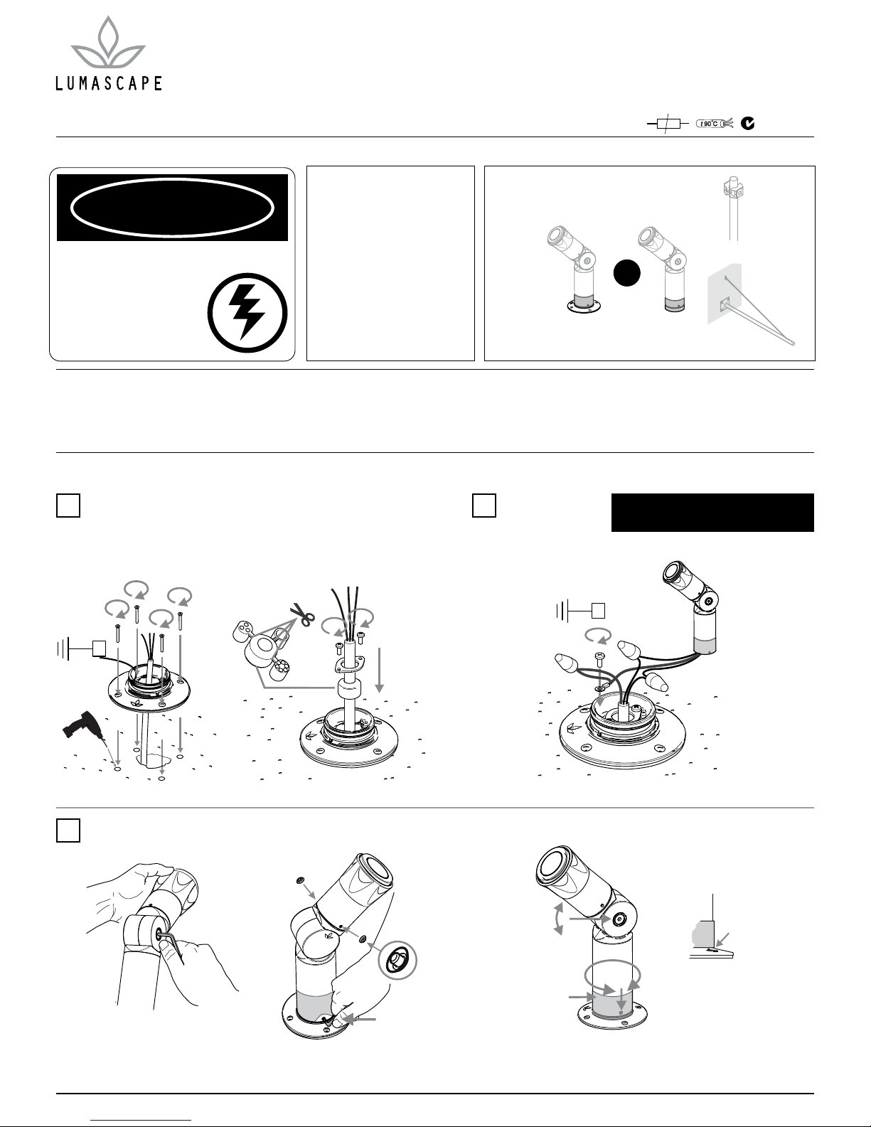
DANGER
ISOLATE LUMINAIRE FROM POWER
Failure to isolate power
supply before installation or
maintenance may result in
fire, serious injury, electric
shock, death and may
damage the luminaire.
Luminaire can become very hot.
Use discretion in placement.
Ensure that installation complies
with local authority standards.
All connections must be kept
dry; failure to do so may result
in product reliability issues.
Screw seals and sleeve must be
fitted or warranty void.
WARNING
LS6023
(ordered separately)
LS411
Surface Mount
Base
LS411
Adaptor Base
LS6025
(ordered separately)
OR OR
LS411
Concrete Anchor /
Spike
Select Mounting Option
See individual mounting accessory
instructions overleaf
1.
Power supply must be isolated prior to
connection or disconnection of cables.
2.
Terminate luminaire.
Select the grommet to suit wiring conductors. Screw mounting base to mounting accessory or screw directly to mounting surface using 4 screws provided
(holes for mounting screws may be supplied blind. Drill through as required
with a 4.5 mm drill. A screw must be used for each hole drilled to achieve IP67
rating.)
Surface Mount Base
For All Mounting Options
Use discretion in placement as luminaire can become very hot and may burn. Run conduit and drill holes as specified.
To aim luminaire loosen socket head screw on the side of the knuckle, position
luminaire and retighten using the 5 mm Allen key supplied.
3.
0.5 Nm
5 Nm
IMPORTANT:
Attach screw seals
Peel back sleeve to
tighten screws
screw seal
base
Sleeve must
meet base
MODEL: LS411LED
INPUT VOLTAGE: 100-240 V AC 50/60 Hz
A.C.N. 0105 72 773
t 90 C
90
o
SPOTLIGHT AND FLOODLIGHT
LS411LED: Line Voltage
E
E
Copyright ©2013 Lumascape Lighting Industries Pty. Ltd. ABN 21 010 572 773
ww w.lumascape.com.au
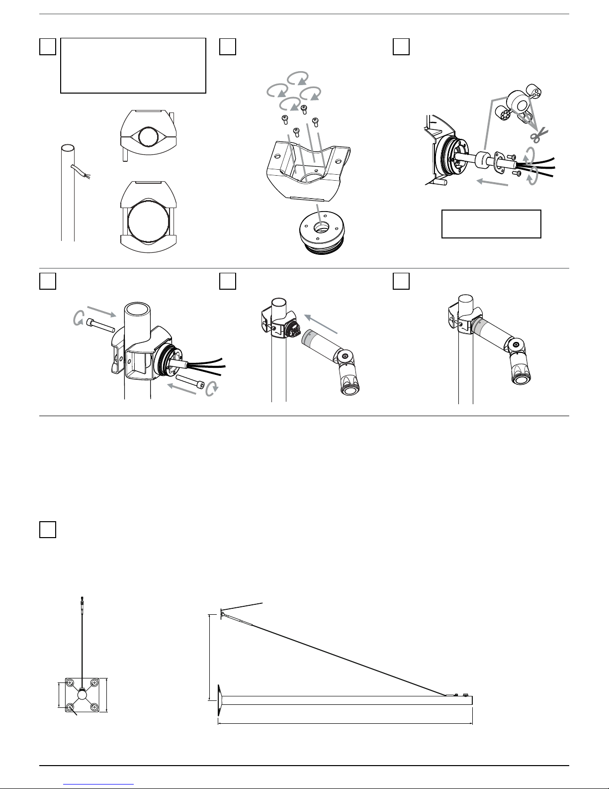
2.
Use M4 x 10 mm screws to fit base
to bracket.
Secure bracket to pole (6 mm Allen key
required).
3.
Fit grommet assembly (Required for IP rating).
1.
4.
LS6023 - pole clamp accessory
Mark luminaire location on post and drill
clearance hole to suit cable used.
NOTE: Cable exit location is aligned central
to luminaire base.
Minimum pipe size
38 mm
(1.5 in)
PIPE SIZE RANGE
78 mm (3.0 in)
Maximum pipe size
Adaptor Base for pole
5. 6.
Connect wiring and fit luminaire to base. Aim luminaire. Refer to Surface Mount Base
section for lamping instructions.
NOTE: Use only 1 x circular
cable to keep IP rating
IN0026 - 26 August 2013
4x Screws/Bolts and Washers
to suit Ø8 mm hole required
2x screws to suit Ø5 mm hole required
Hole Centres
110 mm Square
150 mm Square
1220 mm
450 mm
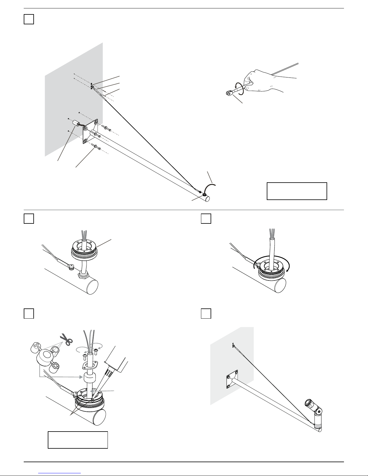
1.
LS6025 - signage system accessory
1. Drill/cast holes and run cables as per lighting plan. Cable will need to exit the mounting surface
into the hollow of the signage pole.
2. Use discretion in placement as luminaire can become very hot and may burn.
3. Select/purchase appropriate stainless steel fasteners for mounting substrate. (Not supplied.)
Adaptor Base for signage
Copyright ©2013 Lumascape Lighting Industries Pty. Ltd. ABN 21 010 572 773
ww w.lumascape.com.au
Base of luminaire
Saddle
Conduit
Supply Cable
Mounting Stud
4x Screws/Bolts and Washers
to suit Ø8 mm hole required
Turnbuckle
Turnbuckle
2x Screws to suit 5 mm hole
2.
3. 4.
1. Feed supply cable through pole until exiting mounting stud at the end.
2. Bolt signage pole to wall.
3. Open turnbuckle to approximately half of it’s adjustment range. Extend the rope assembly up the wall and fasten saddle in place.
4. Fit rope assembly to saddle and lightly adjust tension if required.
Remove base from luminaire and feed through
supply cable.
Screw luminaire base onto mounting stud.
Terminate supply cable.
NOTE: Use only 1 x circular
cable to keep IP rating
IN0026 - 26 August 2013
Cable entry
4x Through
Holes
5. 6.
IMPORTANT: Seal cable entry point and 4 small
holes in base with silicone.
Finalise installation and aim as desired. Refer to Surface
Mount Base section for lamping instructions.
NOTE: Use only 1 x circular
cable to keep IP rating
Copyright ©2013 Lumascape Lighting Industries Pty. Ltd. ABN 21 010 572 773
ww w.lumascape.com.au
IN0026 - 26 August 2013
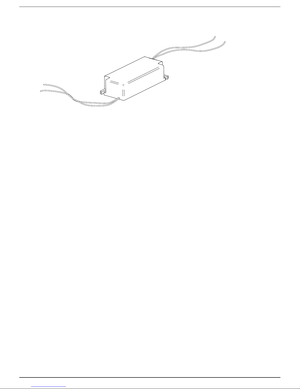
Wiring
LS6095 9 W Single Colour Remote Driver
LS6127 15 W Single Colour Remote Driver
purple or other colour wire - LED+
white wire - ACTIVE
black wire - LED-
black wire - NEUTRAL
WARNING - To reduce the risk of FIRE or INJURY:
1. Luminaires and transformers to be installed by licensed electrical contractors.
2. Luminaires to be used for intended purpose only.
3. Do not operate the luminaires with a missing or damaged parts.
4. Use only genuine Lumascape parts to replace damaged or missing components.
5. Refer to instructions for installation and operating requirements.
6. Ensure installation complies with local regulations
Voltage insulation test (megger) will permanently damage product and will void warranty.
SAVE THESE INSTRUCTIONS.
SAFETY INSTRUCTIONS
 Loading...