

Lumantek VENTUS 2.0 User Manual
VENTUS 2.0 / Manual Updated 2013/2/15
Chapter No. 1-4, Appendix A.B.
P
manual
1. VENTUS Introduction ---------------- 7
1.1 System overview 7
1.2 Development Concept 7
1.3 Pump mode 8
1.4 Basic Organization 8
2 Product Description ----------------- 9
2.1 View and Dimension 9
2.2 Package Contents 10
3 System Operation ------------------- 11
3.1 Hardware Install 11
3.2 Driver Operation 11
3.3 Driver Install 12
3.4 Multi Driver Installation 14
3.5 T-Pump Install 18
4 T-Pump Operation ------------------- 20
4.1 TS-IN Option : ASI Input 22
4.2 TS-OUT Option : ASI Out put 24
4.3 RF OUTPUT Option : CW 24
4.4 RF OUTPUT Option : CW Oeration 26
4.5 RF OUTPUT Option : DVB-T/H(2, 8K) 26
4.6 RF OUTPUT Option : DVB-T/H(4K) 29
4.7 RF OUTPUT Option : DVB-C 31
4.8 RF OUTPUT Option : DVB-S 33
4.9 RF OUTPUR Option : DVB-S2 34
4.10 RF OUTPUR Option : DVB-T2 35
4.11 RF OUTPUT Option : DAB+/DMB+MUX 39
4.12 RF OUTPUT Option : OpenCable 47
4.13 RF OUTPUT Option : ATSC 49
4.14 RF OUTPUT Option : ISDB-T/Tb 51
4.15 RF OUTPUT Option : CMMB 53
4.16 RF OUTPUT Option : ATSC-M/H 64
4.17 AUTO TEST 81
4.18 AWGN
(Addictive White Gaussian Noise)
88
Appendix. A. Ventus User Menu Summary 92
Appendix. B. Ventus API for C/C++ 94
VENTUS 2.0

2
VENTUS 2.0 Manual / Updated 2013/2/15/ Operational Manual
VENTUS 2.0
TRADEMARKS & COPYRIGHT
This document contains information that is
proprietary to LUMANTEK. No part of this publication
may be reproduced, stored in a retrieval system,
or transmitted, in any form, or by any means,
electronically, mechanically, by photocopying, or
otherwise, without the prior written permission of
LUMANTEK. Nationally and internationally recognized
trademarks and trade names are the property of their
respective holders and are hereby acknowledged.
Portions of this software are © 1996-2011 LUMANTEK
Ltd. All intellectual property rights in such portions
of the Software and documentation are owned
by LUMANTEK and are protected by United States
copyright laws, other applicable copyright laws and
international treaty provisions. LUMANTEK and its
suppliers retain all rights not expressly granted.
Disclaimer
The information in this document is furnished for
informational purposes only, is subject to change
without prior notice, and should not be construed
as a commitment by LUMANTEK. The information in
this document is believed to be accurate and reliable;
however LUMANTEK assumes no responsibility or
liability for any errors or inaccuracies that may appear
in this document, nor for any infringements of
patents or other rights of third parties resulting from
its use. No license is granted under any patents or
patent rights of LUMANTEK.
This document was written by the Technical Support
Department of LUMANTEK, Korea. We are committed
to maintaining a high level of quality in all our
documentation. Towards this eort, we welcome your
comments and suggestions regarding the content
and structure of this document. Please fax or mail
your comments and suggestions to the attention of:
LUMANTEK Attn: Product Support Department
Unit 1208, Woolim Lion’s Valley II, 680 Gasan-Dong,
Gumcheon Gu, Seoul Korea (153-830), +82 2 2027
2400, Fax: +82 2 2027 2409
Environmental Issues
Thank you for buying a product which contributes to
a reduction in pollution and thereby helps save the
environment.
Our products reduce the need for travel and transport
and thereby reduce pollution. Our products have
either no or few consumable parts (chemicals, toner,
gas, paper). Our products are low energy consuming
products.
Waste handling:
There is need to send material back to LUMANTEK.
Please contact your local dealerfor information on
recycling the product by sending the main parts of
the product for disassembly at local electronic waste
stations.
Production of products:
Our factories employ the most ecient environmental
methods for reducing waste and pollution by
ensuring that
the products are recyclable.

3
VENTUS 2.0 Manual / Updated 2013/2/15/ Operational Manual
VENTUS 2.0
3
For your protection, please read these safety
instructions completely before operating the
equipment and keep this manual for future reference.
The information in this summary is intended for
operators. Carefully observe all warnings, precautions
and instructions both on the apparatus and in the
operating instructions.
Equipment Markings
The lighting ash symbol within an equilateral triangle
is intended to alert the user to the presence of un
insulated “dangerous voltages” within the product’s
enclosure that may be of sucient magnitude to
constitute a risk of electrical shock. The exclamation
mark within an equilateral triangle is intended to alert
the user to the presence of important operating and
maintenance (servicing) instructions within literature
accompanying the equipment.
Warnings
Water and Moisture :
Do not operate the equipment under or near water - for
example near a bathtub, kitchen sink, or laundry tub, in
a wet basement, near a swimming poor or in areas with
high humidity. Cleaning - Unplug the apparatus from
the wall outlet before cleaning or polishing. Do not use
liquid cleaners or aerosol cleaners. Use a lint-free cloth
lightly moistened with water for cleaning the exterior
of the apparatus.
Ventilation :
Do not block any of the ventilation openings of the
apparatus. Install in accordance with the installation
instructions. Never cover the slots and openings with a
cloth or other material. Never install the apparatus near
heat sources such as radiator, heat registers, stoves, or
other apparatus (including ampliers) that produce
heat.Grounding or Polarization - Do not defeat the
safety purpose of the polarized or grounding-type
plug. A polarized plug has two blades with one wider
OPERATOR SAFETY SUMMARY
than the other. A grounding type plus has two blades
and a third grounding prong.
The wide blade or third prong is provided for your
safety. If the provided plug does not t into your outlet,
consult an electrician. Power-Cord Protection - Route
the power cord so as to avoid it being walked on or
pinched by items placed upon or against it, paying
particular attention to the plugs, receptacles, at the
point where the cord exits form the apparatus.
Attachments :
Only use attachments as recommended by the
manufacture.
Accessories :
Use only with a cart, stand, tripod, bracket, or table
specied by the manufacturer, or sold with the
apparatus. When a cart is used, use caution when
moving the cart/apparatus combination to avoid injury
from tip-over.
Lighting :
Unplug this apparatus during lightning storms or when
unused for long periods of time.
ISDN cables :
CAUTION - to reduce the risk of re, use only No. 26
AWG or larger telecommunication line cord.
Servicing :
Do not attempt to service the apparatus yourself
as opening or removing covers may expose you to
dangerous voltages or other hazards, and will void
the warranty. Refer all servicing to qualied service
personnel.
Damaged Equipment :
Unplug the apparatus from the outlet and refer
servicing to qualied personnel under the following
conditions - When the power cord or plug is damaged
or frayed If liquid has been spilled or objects have fallen
into the apparatus If the apparatus has been exposed

4
VENTUS 2.0 Manual / Updated 2013/2/15/ Operational Manual
VENTUS 2.0
to rain or moisture If the apparatus has been subjected
to excessive shock by being dropped, or the cabinet
has been damaged If the apparatus fails to operate in
accordance with the operating instruction
Warranty Period
Lumantek Test & Measurement and Broadcasting
products normally carry a 1-year limited warranty
(including labor and parts) Unless noted, Lumantek
Digital Media products normally carry a 1-year limited
warranty (including labor and parts).
Return Material Authorization Policy
No product may be returned directly to Lumantek
without rst contacting Lumantek for a Return Material
Authorization (“RMA”) Code. If it is determined that the
product is defective, you will be given an RMA Code
and instructions for product return for servicing or
replacement. An unauthorized return such as where
an RMA Code has not been issued, the product will be
returned to you at your expense. Authorized returns are
to be shipped prepaid and insured to the address on
the RMA in an approved shipping container (original
box and packaging materials or similar). To request an
RMA Code, please visit on http://www.lumantek.com/
support/rma_services_instruction.html
Warranty Limitations
Lumantek’s limited warranty provides that, subject to
the following limitations, each product will be free from
defects in material and workmanship and will conform
to Lumantek’s specication for the particular product.
Limitation of Remedies
Your exclusive remedy for any defective product is
limited to the repair or replacement of the defective
product.
Lumantek may elect which remedy or combination of
remedies to provide in its sole discretion. Lumantek
shall have a reasonable time after determining that a
defective product exists to repair or replace a defective
product. Lumantek’s replacement product under its
limited warranty will be manufactured from new and
serviceable used parts. Lumantek’s warranty applies
to repaired or replaced products for the balance of
the applicable period of the original warranty or
ninety days from the date of shipment of a repaired or
replaced product, whichever is longer.
Limitation of Damages
Lumantek’s entire liability for any defective product
shall in no event exceed the purchase price for the
defective product. This limitation applies even if
Lumantek cannot or does not repair or replace any
defective product and your exclusive remedy fails of its
essential purpose.
No Consequential or Other Damages
Notwithstanding anything else in this policy or
otherwise, Lumantek will not be liable with respect
to the products under any contract, negligence,
strict liability or other legal or equitable theory (i) for
any amount in excess of the purchase price for the
defective product or (ii) for any general, consequential,
punitive, incidental or special damages. These include
loss of recorded data, interruption of use, the cost of
recovery of lost data, lost prots and the cost of the
installation or removal of any products, the installation
of replacement products, and any inspection, testing,
or redesign caused by any defect or by the repair or
replacement of products arising from a defect in any
product. This section does not limit liability for bodily
injury of a person.

5
VENTUS 2.0 Manual / Updated 2013/2/15/ Operational Manual
VENTUS 2.0
Your Use of the Product
Lumantek will have no liability for any product returned
if Lumantek determines that:
The product was stolen from Lumantek.
The asserted defect:
- Is not present,
- Cannot reasonably be xed because of damage
occurring when the product is in the possession of
someone other than Lumantek, or
- Is attributable to misuse, improper installation,
alteration (including removing or obliterating labels and
opening or removing external covers (unless authorized
to do so by Lumantek), accident or mishandling while in
the possession of someone other than Lumantek.
The product was not sold to you as new.
The product was not used in accordance with Lumantek
specications and instructions.
The product was not used for its intended function.
Additional Limitations on Warranty
Lumantek’s warranty does not cover products which
have been received improperly packaged, altered, or
physically damaged.
6
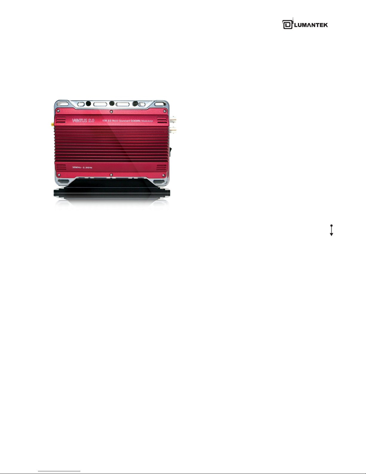
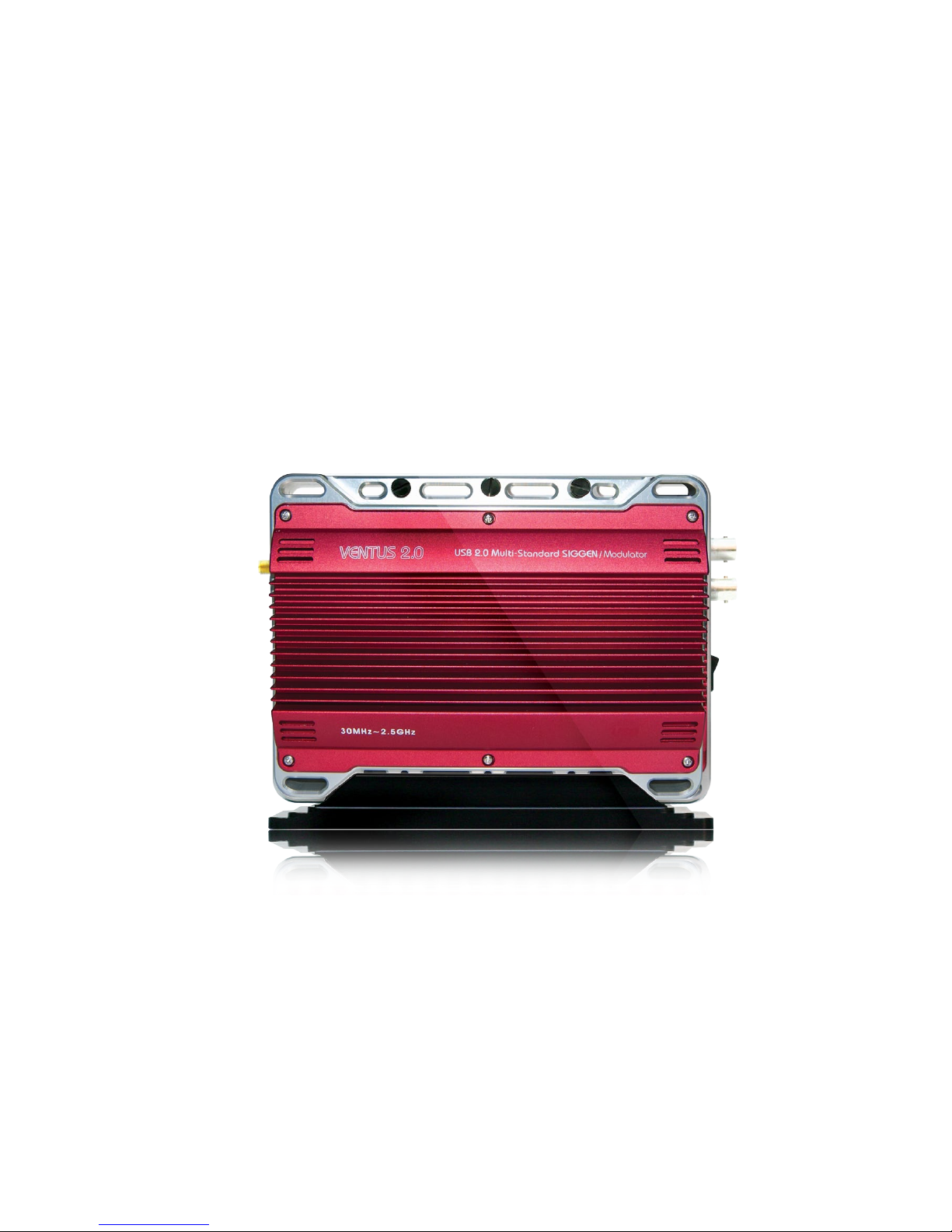
USB 2.0 Multi-Standard SIGGEN / Modulator
Frequency 30MHz ~ 2.5GHz
VENTUS 2.0
7
VENTUS 2.0 Manual / Updated 2013/2/15/ Operational Manual
VENTUS 2.0
1.1 / VENTUS System Overview
1.2 / VENTUS Development Concept
1. VENTUS 2.0 / Introduction
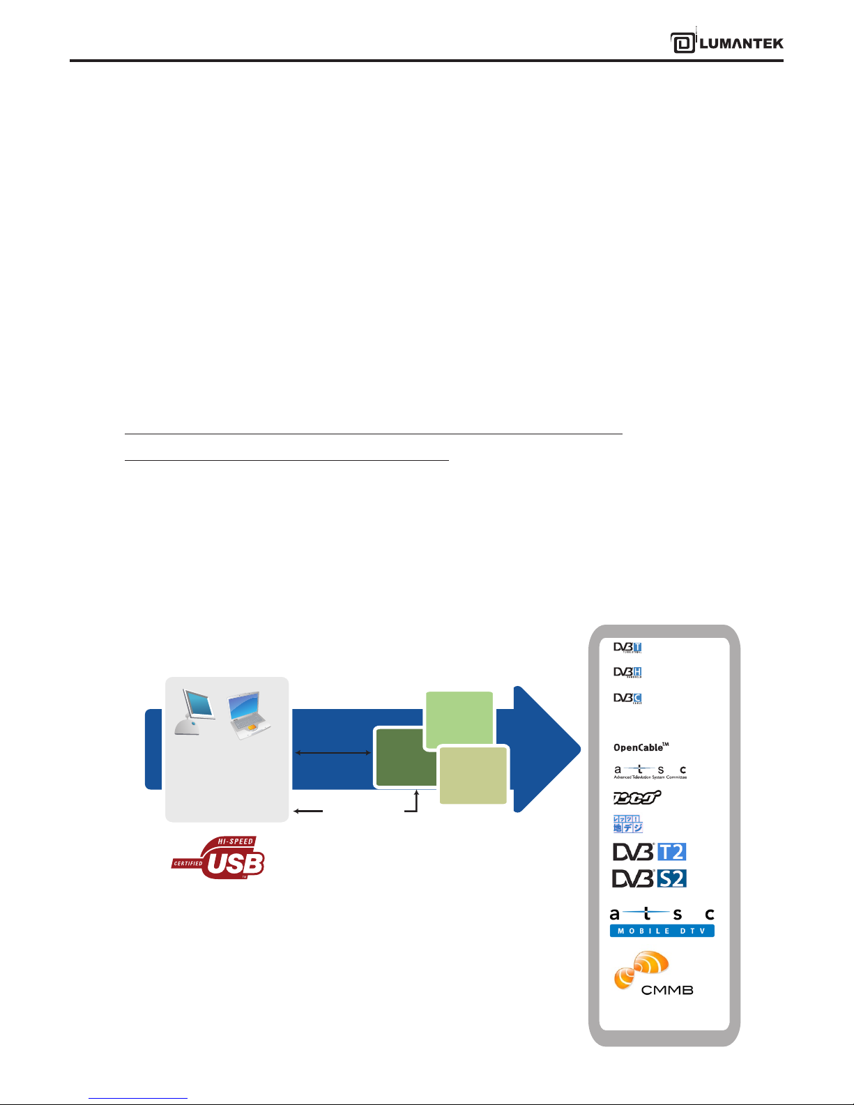
VENTUS is a product that broke away from the existing measurement system. It is designed so that it can be con-
nected to the user’s PC or notebook USB interface. It is a portable measurement system unlike the existing Signal
Generator. It can be used for many purposes such as development, product demonstration, marketing, and domestic
and overseas business trip purposes.
Basically, it consists of ASI-INPUT, ASI-OUTPUT port, RF Modulator, and RF Upconverter. If the user wants, any DTV SD
format in the world can be used. DTV SD formats supported by VENUS are as follows.
DVB-T/H, DVB-C (A,C), ATSC(8VSB), ATSC-M/H, OpenCable, ISDB-T/Tb,
T-DMB/DAB+, CMMB, DTMB, DVB-T2, DVB-S2
VENTUS solution can be used to test all DTV SD formats in the world. It is a All-in-One type measurement solution. As
it is a portable product, it has maximized user convenience.
Desktop
Computer
Laptop
Computer
Ventus
Application
ASI OUT
ASI IN
Ventus
RF OUT
Upcoverter
Attenuator
T-DMB/DAB+
8
VENTUS 2.0 Manual / Updated 2013/2/15/ Operational Manual
VENTUS 2.0
1.3 / T-Pump Mode
1.4 / VENTUS Basic Organization
Pump has the interface for USB IN/OUT and ASI IN/OUT RF OUT(Data). Also it has 8M Byte or 16M Byte’s Hardware Buf-
fer inside the pump. Pump’s mode are RF OUT. RF OUT Raw. ASI OUT. ASI IN. ASI IN to RF OUT. Please reference below
explains, VTS_PumpMode_t type declaration and the PumpSet Mode function.
RF OUT Mode: This mode is that MPEG transmit stream (TS, Transport Stream), ports by USB IN, sends it as RF
OUT(Data) through H/W buer.
RF OUT Raw Mode: This mode is received the reated byte stream at software through USB INand sends it as RF OUT
(date) through H/W buer.
ASI OUT Mode: This mode is to get MPEG TS by USB IN, then put it out as ASI OUT through H/W buer.
ASI IN Mode: This mode is to get MPEG TS by ASI IN, then put it out to USB OUT through H/W buer. Also, this mode
is possible to output as selective ASI OUT at the same time.
ASI IN to RF OUT Mode: This mode is to get MPEG TS by ASI IN, then put it out to RF OUT. Also, this mode is possible
to output as selective ASI OUT at the same time.
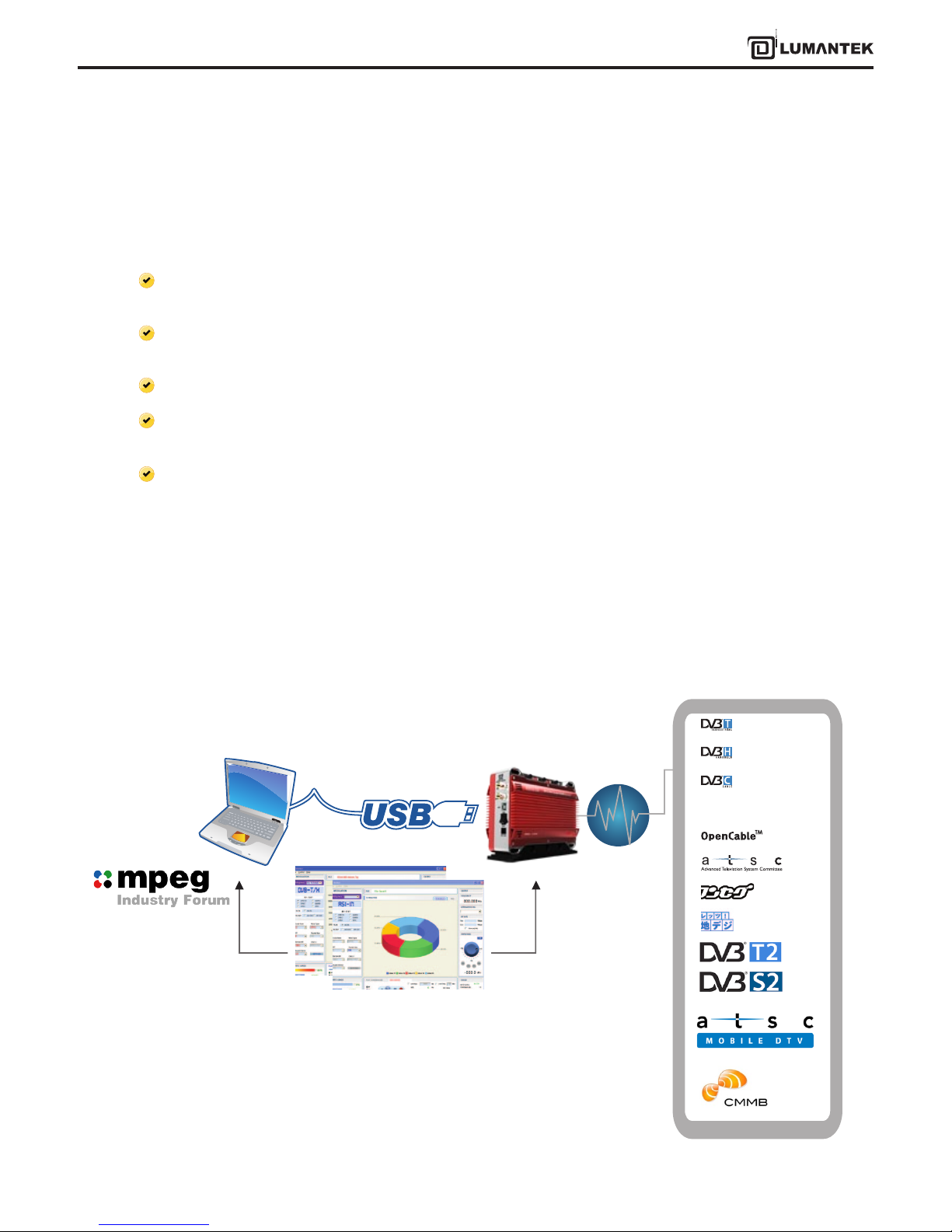
VENTUS device is possible to transmit DTV Skill Standard by RF through USB Interface between VENTUS and PC or
Notebook.
VENTUS Basic Organization
TS Stream
T-pump (VENTUS Application)
T-DMB/DAB+
9
VENTUS 2.0 Manual / Updated 2013/2/15/ Operational Manual
VENTUS 2.0
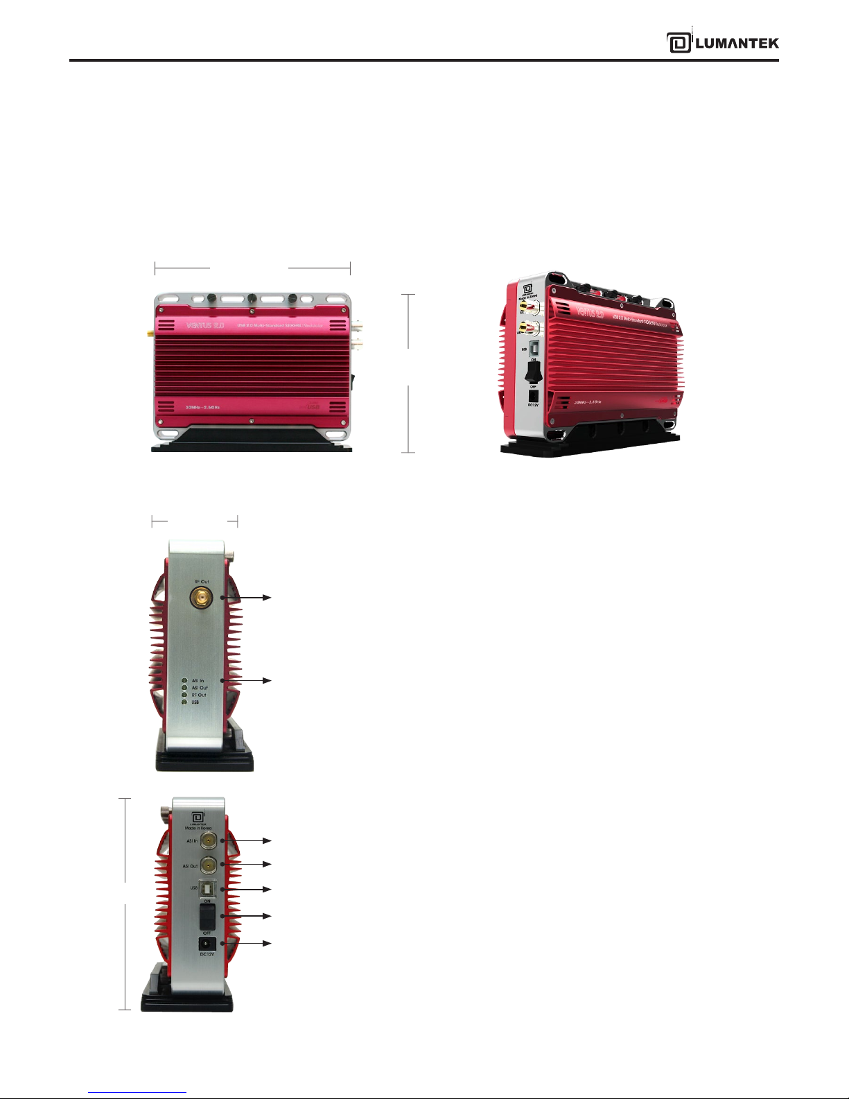
2.1 / Product Views and Dimensions
2. VENTUS 2.0 / Product Description
- USB LED: (On) when connected USB
- RF OUT LED: (On) under normal RF Output
- ASI IN LED: (On) when using ASI Input Port
- ASI OUT LED: (On) when using ASI Output Port
- RF OUT (-20dBm) : RF Output Port
- POWER SW: VENTUS power Switch
- POWER port
- Attenuator Power : Power connecting port
-> When using Amp & Attenuator, it controls by USB port
-> USB port connects Ventus
- ASI-OUT : ASI Out port
- ASI-IN : ASI Input port
FRONT Perspective
140 mm
200 mm
RF Output
Status LED
Right Side Panels Interface
Left Side Panels Interface
120 mm
ASI IN
USB IN
POWER
PWR SW
ASI OUT
70 mm
10
VENTUS 2.0 Manual / Updated 2013/2/15/ Operational Manual
VENTUS 2.0
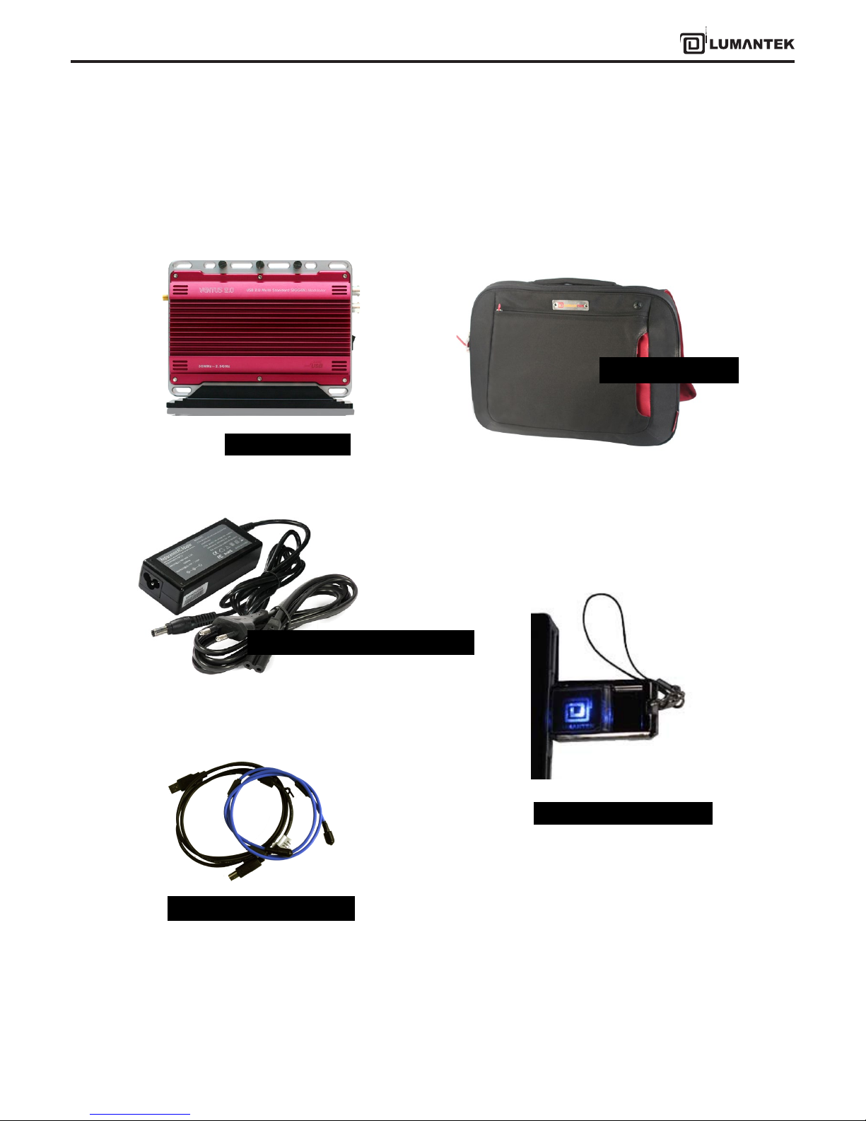
2.2 / VENTUS 2.0 Package Contents
VENTUS 2.0 Body
AC Power Adapter & AC Power Cord
VENTUS Portable Case
VENTUS Driver / T-pump /
Software / Manual
Calibration Report
Antenna USB Cable : A-B Type
USB Flash Memory & Strap
11
VENTUS 2.0 Manual / Updated 2013/2/15/ Operational Manual
VENTUS 2.0
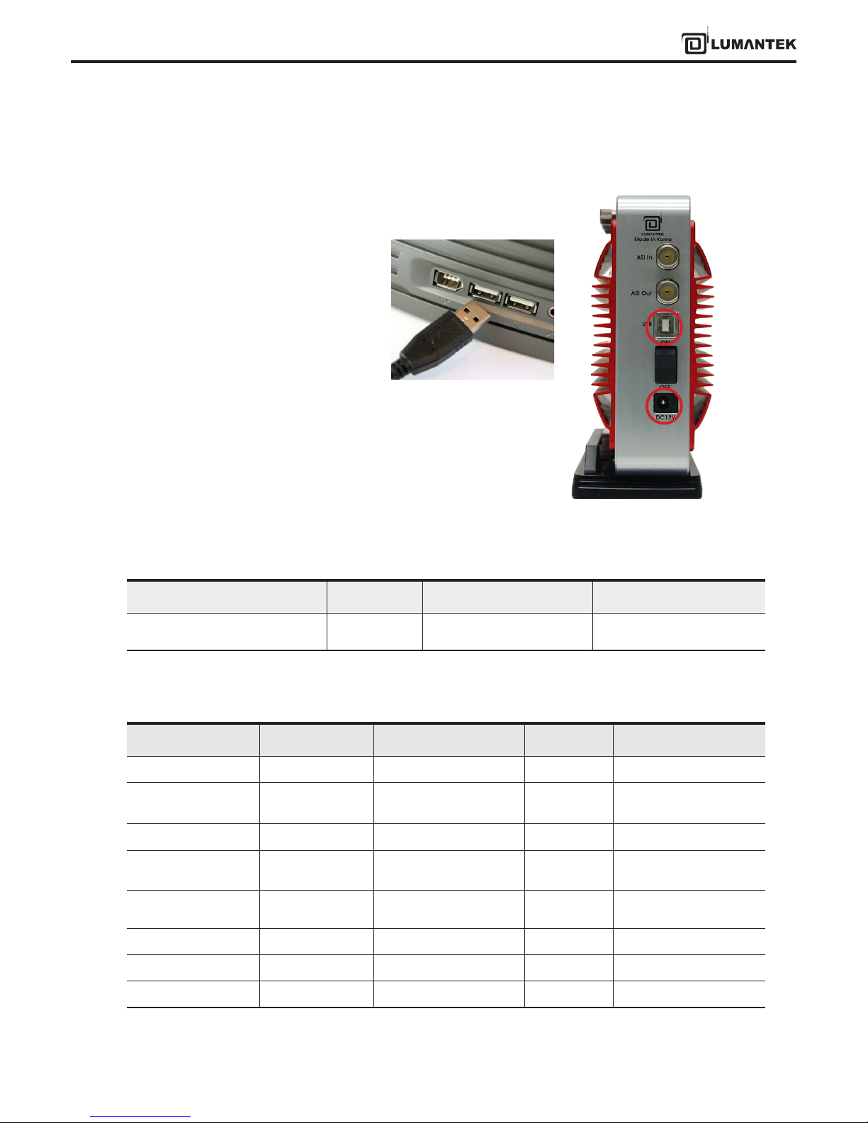
3.1 / VENTUS Hardware Install
3.2 / VENTUS Driver Operation
* VHF/UHF RF Attenuator (Optional)
As explained in Chapter 2, after check-
ing VENTUS components, the user can
use it after just connecting power and
installing T-pump without installing
the hardware. Connect Power and PC
or Notebook’s USB cable(A-B Type) to
VENTUS’ USB port.
For operating VENTUS, you have to install DVB-ASI In/Out Module Driver and VENTUS Modulator Driver.
-> Insert the USB Flash Memory and download the Driver from USB.
Driver Name Folder name Description OS
USB DTV Signal Generator
(LUMANTEK)
Driver.install
VENTUS 2.0 DTV Signal
Generator
Window XP / 2000 /2003 /
Window7
3. VENTUS 2.0 / SYSTEM OPERATING
USB Port
Power Cord
Item Unit Min. Type Max
Input Range dBm - -20 -
Output Control Range dBm -110 -
+7 dBm(+3dbm over
frequency of 1GHz)
Output Control Step dB - 0.1 -
Frequency Control
Range
MHz/GHz 30MHz - 2.5GHz
Frequency Control Step MHz - 0.001 -
Valid Temperature Celsius (ºC) 25 38 60
Power Supply Voltage V - 12V -
Power Supply Current mA - 1A 1.3A
12
VENTUS 2.0 Manual / Updated 2013/2/15/ Operational Manual
VENTUS 2.0
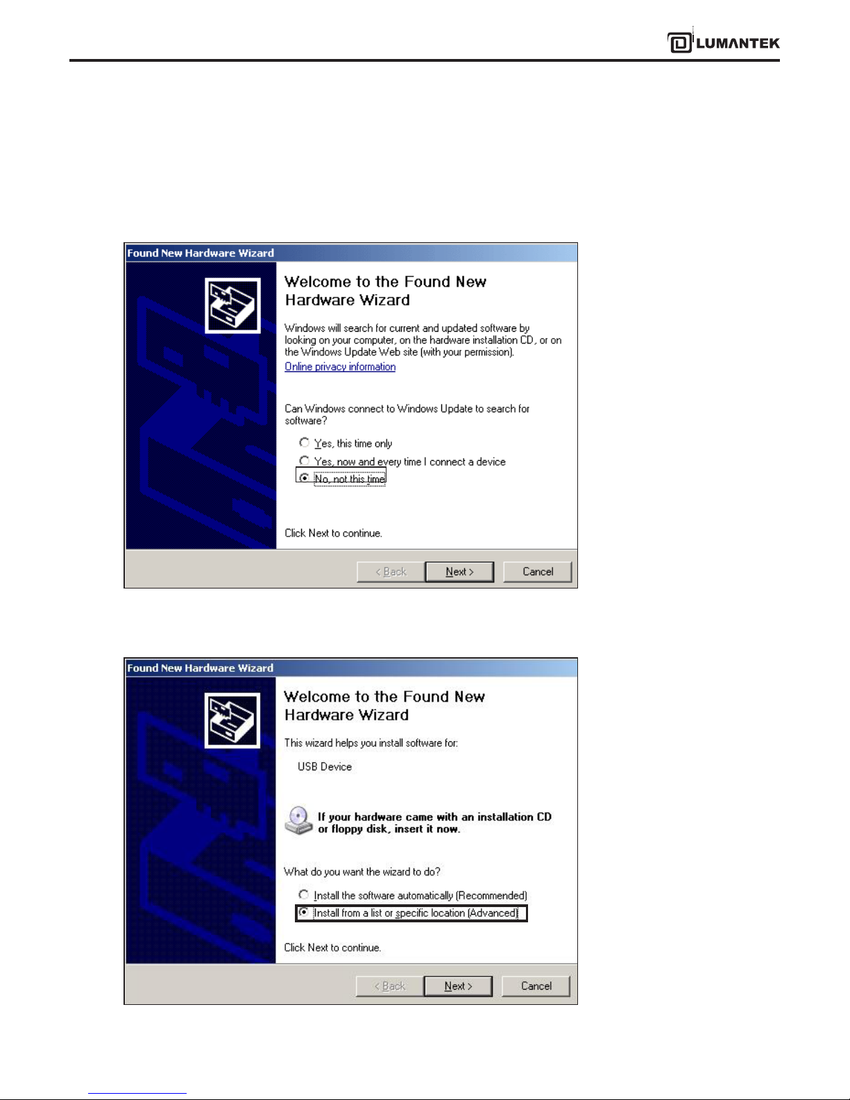
3.3 / VENTUS Driver Installation
Upon connecting the VENTUS for the rst time, “Found New Hardware Wizard” window will pop up. Check “No, not this
time”, then click “Next”.
Select “Install from a list or specic location(Advanced)”, then click “Next”.
13
VENTUS 2.0 Manual / Updated 2013/2/15/ Operational Manual
VENTUS 2.0
Click [Browse] and go to the le location. It’s placed at [..\VENTUS\Driver.install] in supplied USB Flash Memory. Choose
the one folder between Window OS 32bit and 64 bit.
Continue installing.
Once you’ve nished installing driver, you need to
check out the device manager. On windows XP,
you can check it by going to the Control Panel, click
System. And click Hardware. A Device Manager
should look like the picture below.
14
VENTUS 2.0 Manual / Updated 2013/2/15/ Operational Manual
VENTUS 2.0
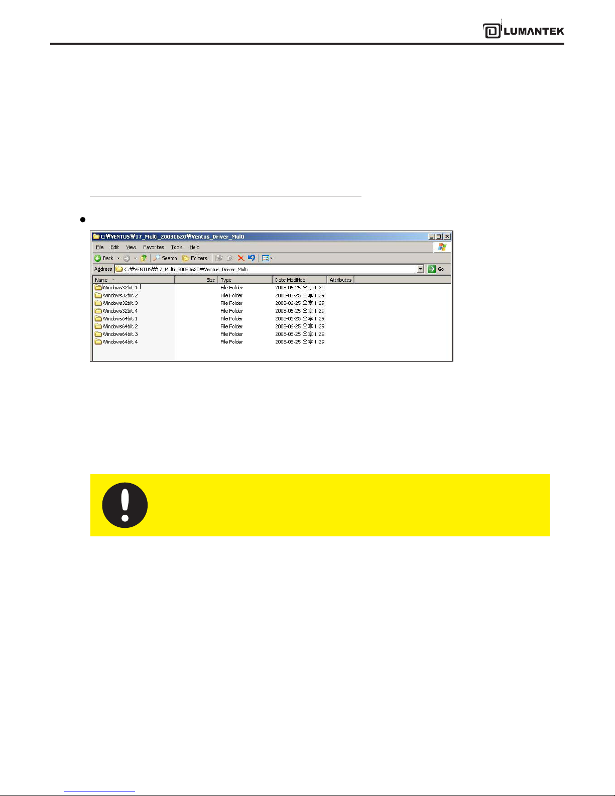
3.4 / VENTUS Multi Driver Installation
In case you need to operate more than 2 VENTUS on one computer, you must use dierent drivers for operating.
Other USB. USB device has 2 type of VID(Vendor ID) and PID(Product ID). However, you may use separated drive for
instance. In this case you need a dierent driver le and installation le(*.inf ).
You can operate them upto 4 Ventus depend on your computer’s spec.
In the latest T-pump is possible to install driver per each number like above image.
Windows 32bit(1-4): Windows 2000, XP, 2003, Vista(32 bit).
Windows 64 bit(1-4): Windows XP, 2003, Vista(64 bit).
Multi- Driver installation processes same as 3.3
Package Contents
For the reference, USB device will read dierent devices as the port. if you connect them through
PC’s same port using outside hub, it will read as a dierent device and install driver again.
15
VENTUS 2.0 Manual / Updated 2013/2/15/ Operational Manual
VENTUS 2.0
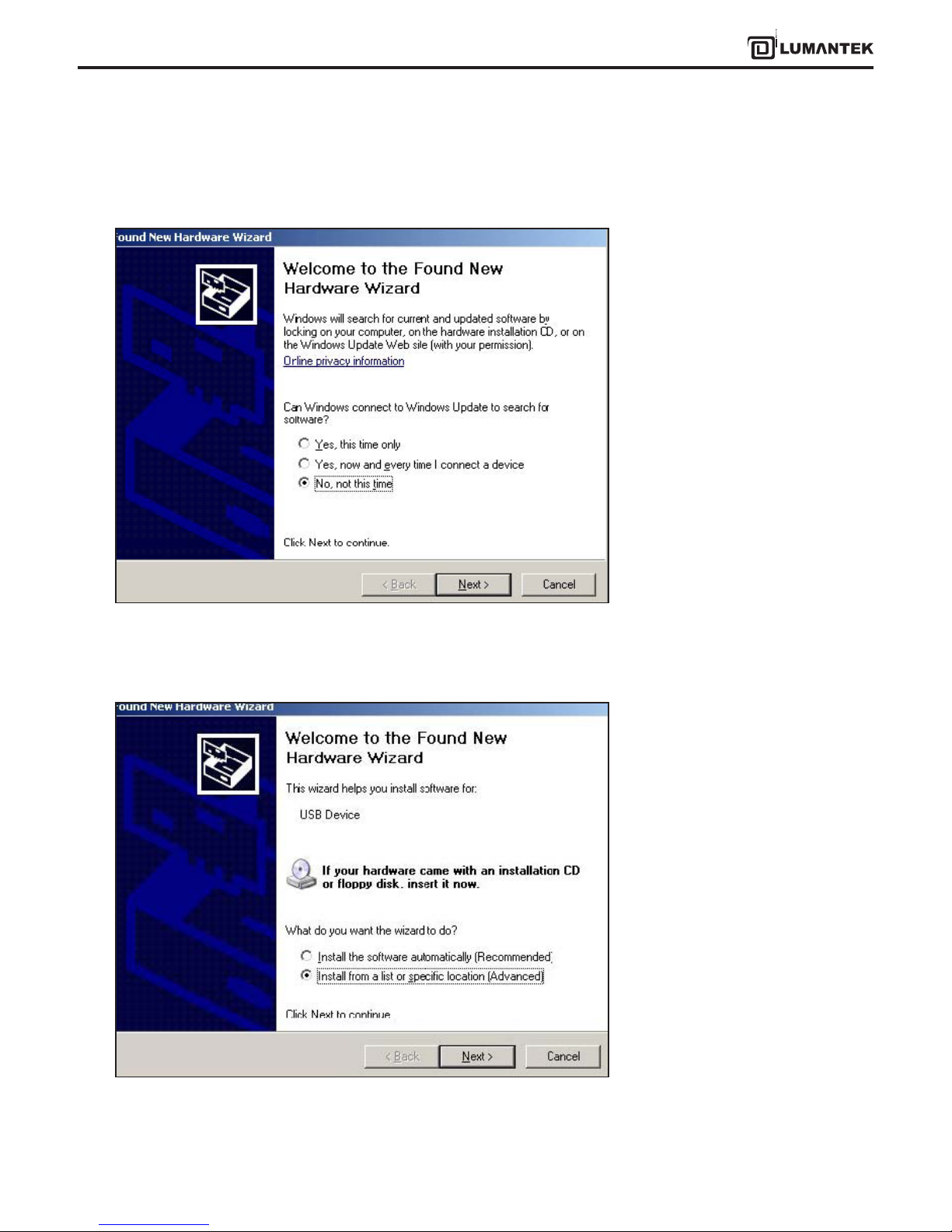
Windows will recognize it as a new hardware component and open the “Found New Hardware Wizard”. Click on ‘No, not
this time’, then Click ‘Next’.
Check ‘Install from a list or specic location (Advanced)’. Then click ‘Next’.
16
VENTUS 2.0 Manual / Updated 2013/2/15/ Operational Manual
VENTUS 2.0
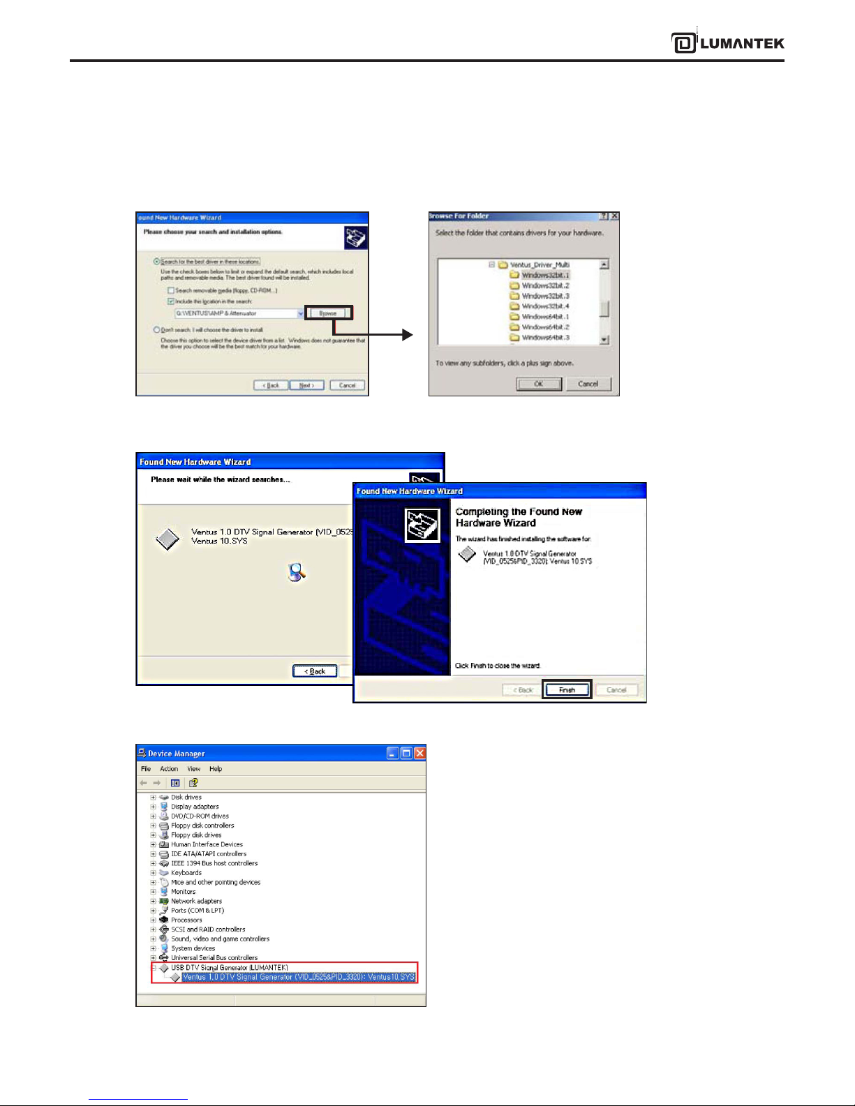
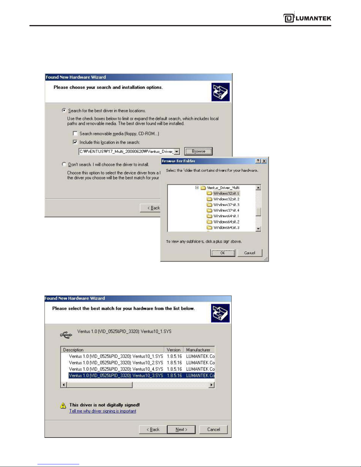
Select ‘Search for best driver in these locations’. Then, Click ‘Browse’
Navigate to the correct installation search path and assign the Driver path which doesn’t use before.4. Assign the driver
except the existing ports.
For instance, if you assian driver
No.1 before, you have to choose
other driver
numbers. We recommand use
same number of drivers to
number of devices.
17
VENTUS 2.0 Manual / Updated 2013/2/15/ Operational Manual
VENTUS 2.0
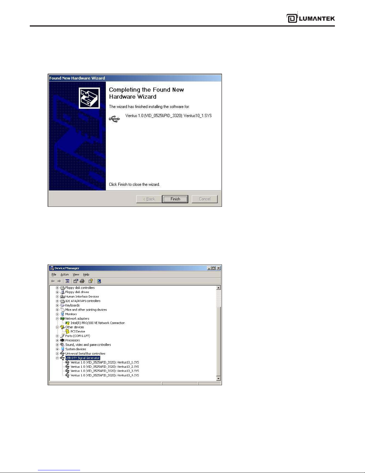
The Wizard shows that the installation has been completed.
Expand the USB DTV Singal Generator Driver in the Windows Device Manager (Control Panel > System > select Hardware
tab> click on Device Manager).
You can nd your installed several VENTUS drivers.
18
VENTUS 2.0 Manual / Updated 2013/2/15/ Operational Manual
VENTUS 2.0
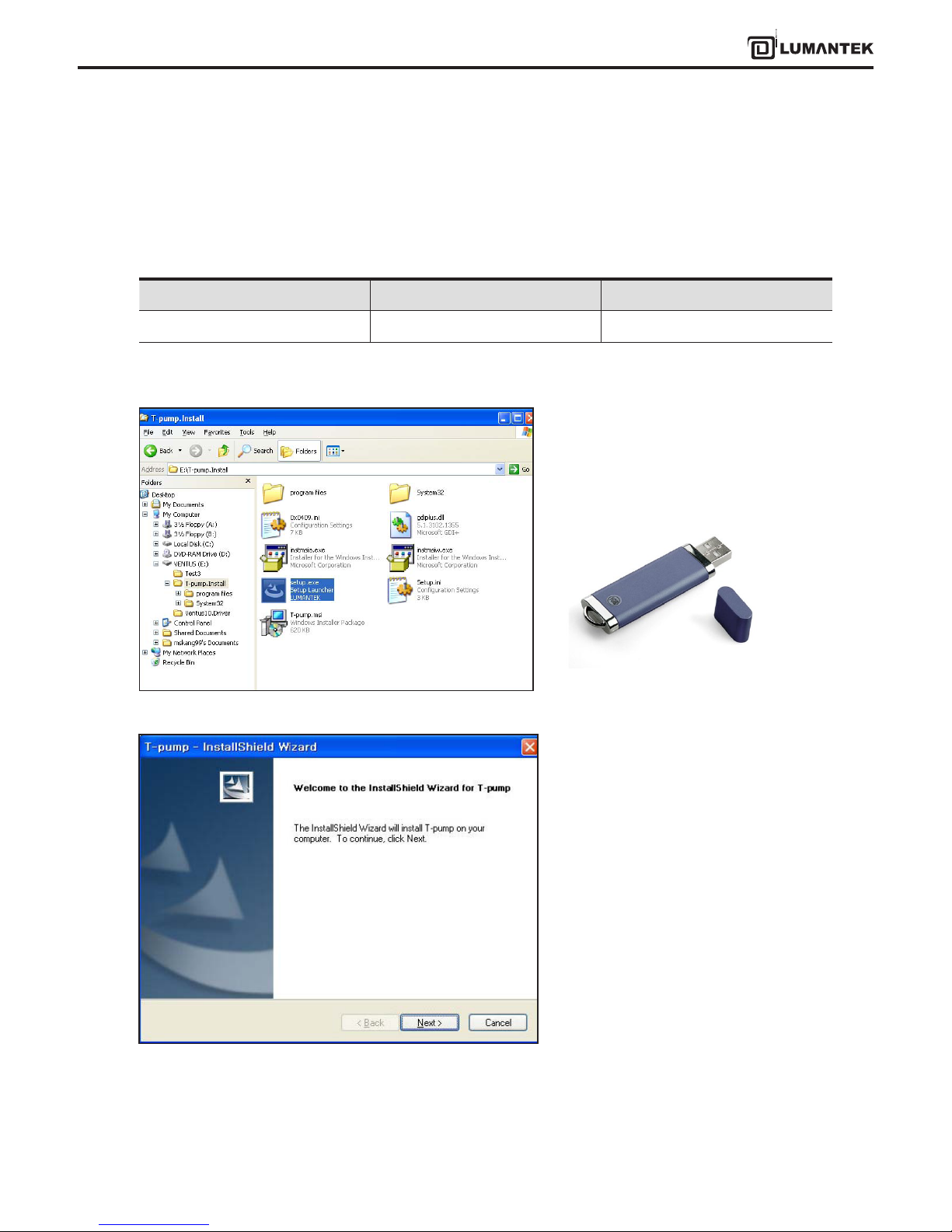
3.5 / VENTUS T-pump Install
After completing the installation of VENTUS device driver, install T-pump software, which is provided for the operation
of VENTUS, in the PC or notebook. T-pump is a program that controls all VENTUS interfaces. It controls recording, RF
transmission, ASI transmission, and DTV selection functions.
Firstly, double click ”Setup.exe”.
Including in the USB provided
T-Pump install program will run.
Program Name Folder Name Description
Setup.exe T-pump Install VENTUS Application
19
VENTUS 2.0 Manual / Updated 2013/2/15/ Operational Manual
VENTUS 2.0
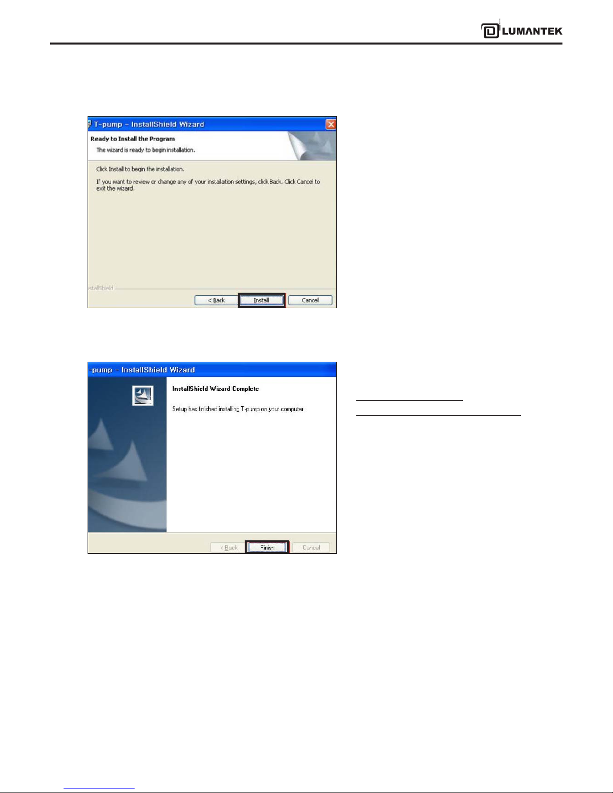
Continue T-pump installing.
The T-pump installation has been completed.
T-pump Program location :
[ C:\Program Files\(C)LUMANTEK\T-Pump ]

20
VENTUS 2.0 Manual / Updated 2013/2/15/ Operational Manual
VENTUS 2.0
After completing the installation of VENTUS device driver and T-pump software, test DTV signal transmission,
and capturing and transmission using ASI input/out using the T-pump software.
• Auto Test program works, When turn o the Ventus with ASI card.
• New option for T-DMB Mode
-> TM2, TM3, TM4 can transmits
• New option for CMMB Mode
-> Added EMM sign on Data eld.
-> Add CAS eld
-> The T-pump works, even CLCH information and the actual form does not match each other.
-> Fixed no padding data sync error rountine
-> Fixed the problem to apply in order the MF-ID when the Multi-MFS is deleted.
• Edit the problem when Lower than the range of frequency settings, it sets automatically set to the value of
the minimum
• Full-seg stream as a stream of TMCC information without modication to the output when 1 seg
• From this version, it supporting Window Vista for USB Driver
4. VENTUS 2.0 / TPUMP OPERATION
Upgrade Information (Version 3.1.0)
21
VENTUS 2.0 Manual / Updated 2013/2/15/ Operational Manual
VENTUS 2.0
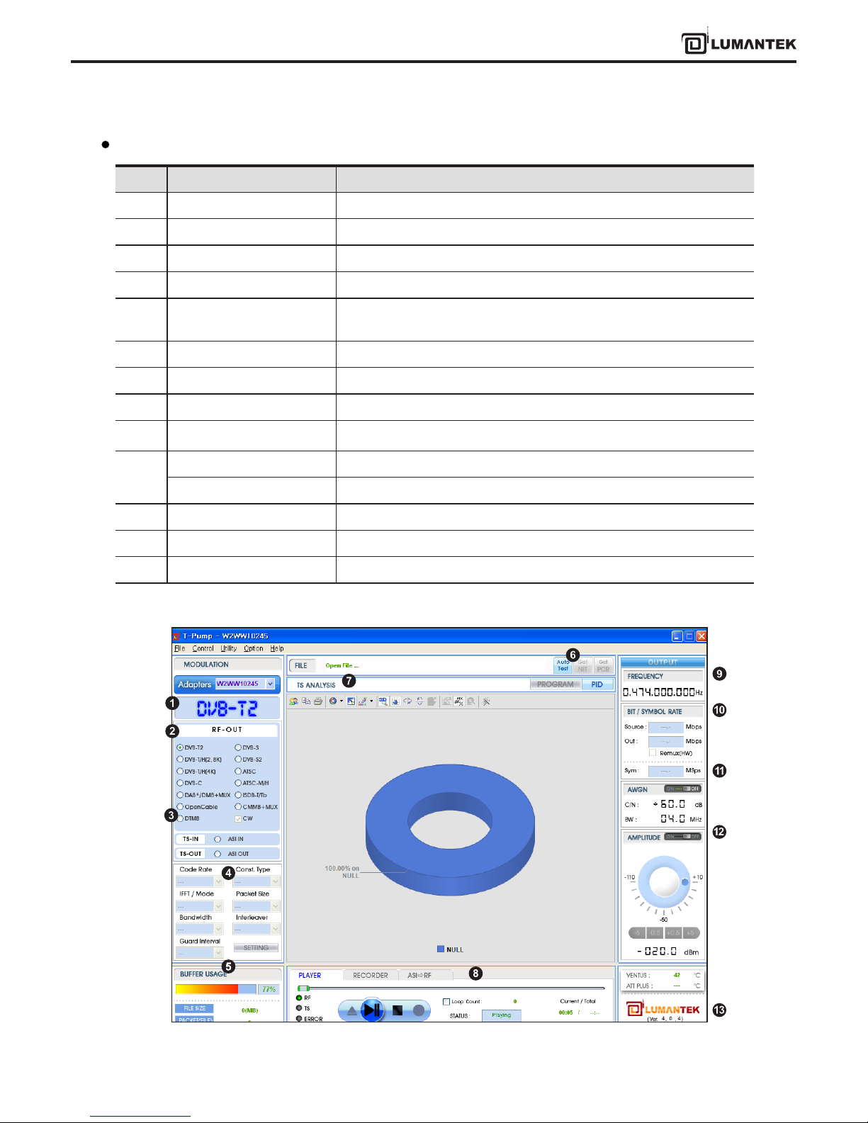
No Items Description
1 ASI-IN, OUT, DVB-T/H etc. Display selected Interface
2 RF-OUT DTV Option-> When this option is selected, the interface will change
3 TS-IN / OUT Select ASI INPUT, OUTPUT Port
4 RF Parameter Set DTV Parameter, RF OUTPUT Mode in detail
5 BUFFER USAGE Display hardware buer information usage of current selected interface
stream
6 Get NIT, Get PCR Check DVB-T,H stream’s NIT information
7 TS ANALYSIS Analyses per Program and PID
8 Play / Record / ASI to RF TS Play control, Capturing by ASI INPUT, ASI Input -> RF output
9 Frequency
Set frequency for testing
10 Bit rate Bit Rate of the testing TS File( source, output)
From File Check DVB-T stream’s NIT
11 Symbol rate Input Symbol Rate under DVB-C mode
12 Amplitude Power Level Control
13 Version Display T-PUMP Version
T-pump UI Overview
22
VENTUS 2.0 Manual / Updated 2013/2/15/ Operational Manual
VENTUS 2.0
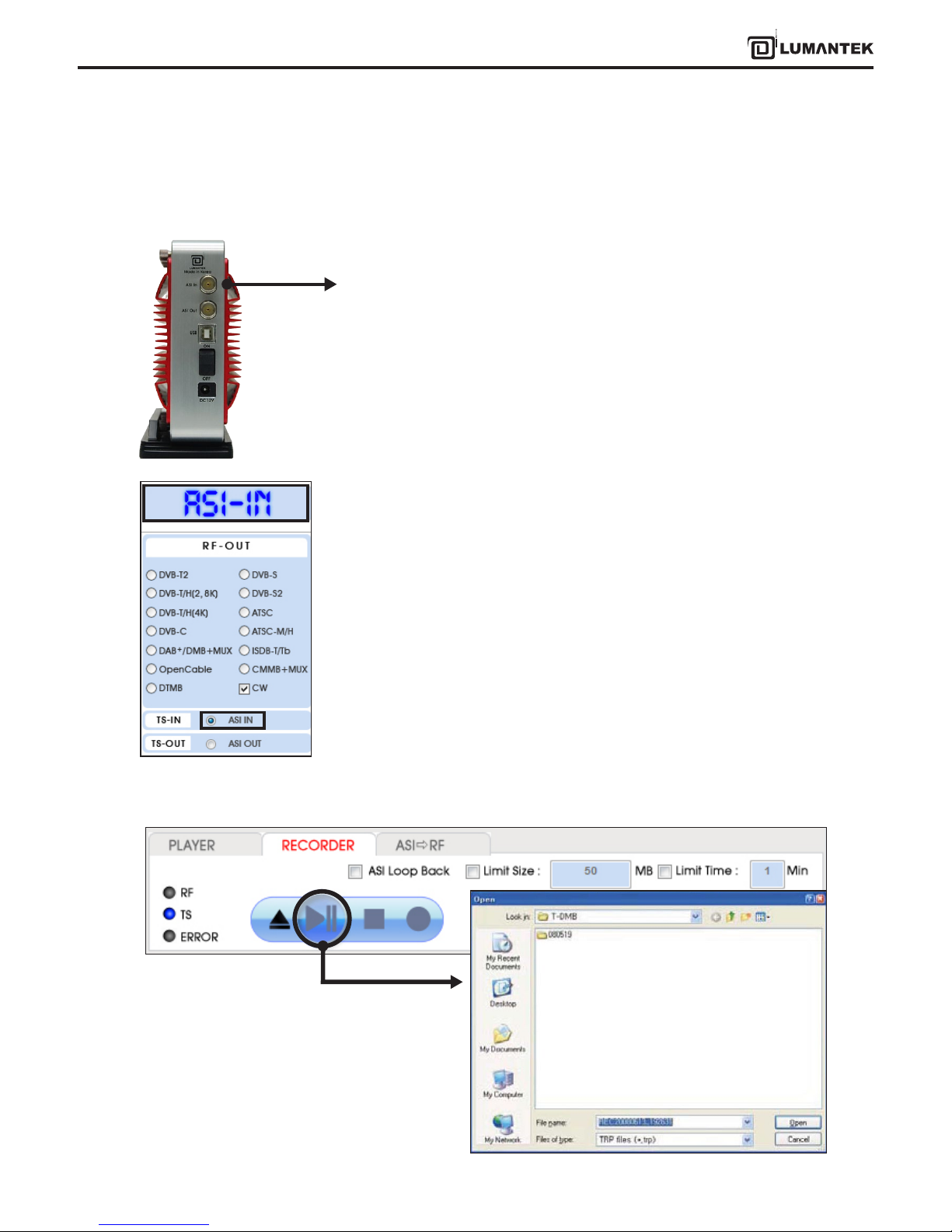
4.1 / TS-IN Option : ASI Input
1. ASI Input is for input real time stream from other ASI Output Port.
2. First, run T-pump application. -> Then on your left side menu, click TS-IN. -> On
Top Left Menu will change to ASI-IN signal.
3. When you want to capture the signal which is entering through ASI Input, Click Open icon. File browse window
will pop up.
23
VENTUS 2.0 Manual / Updated 2013/2/15/ Operational Manual
VENTUS 2.0
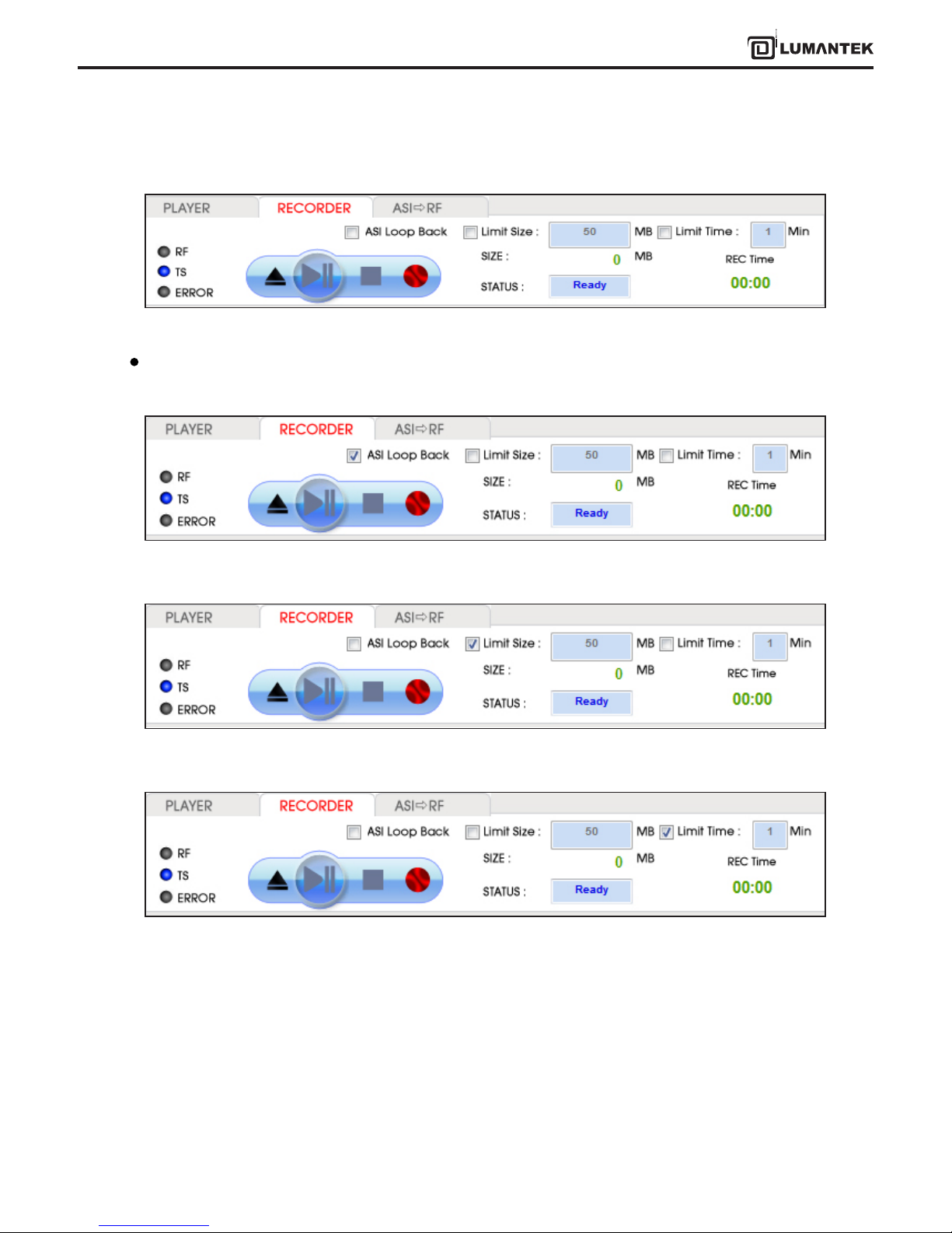
4. Click Rec button under RECORDER tab.
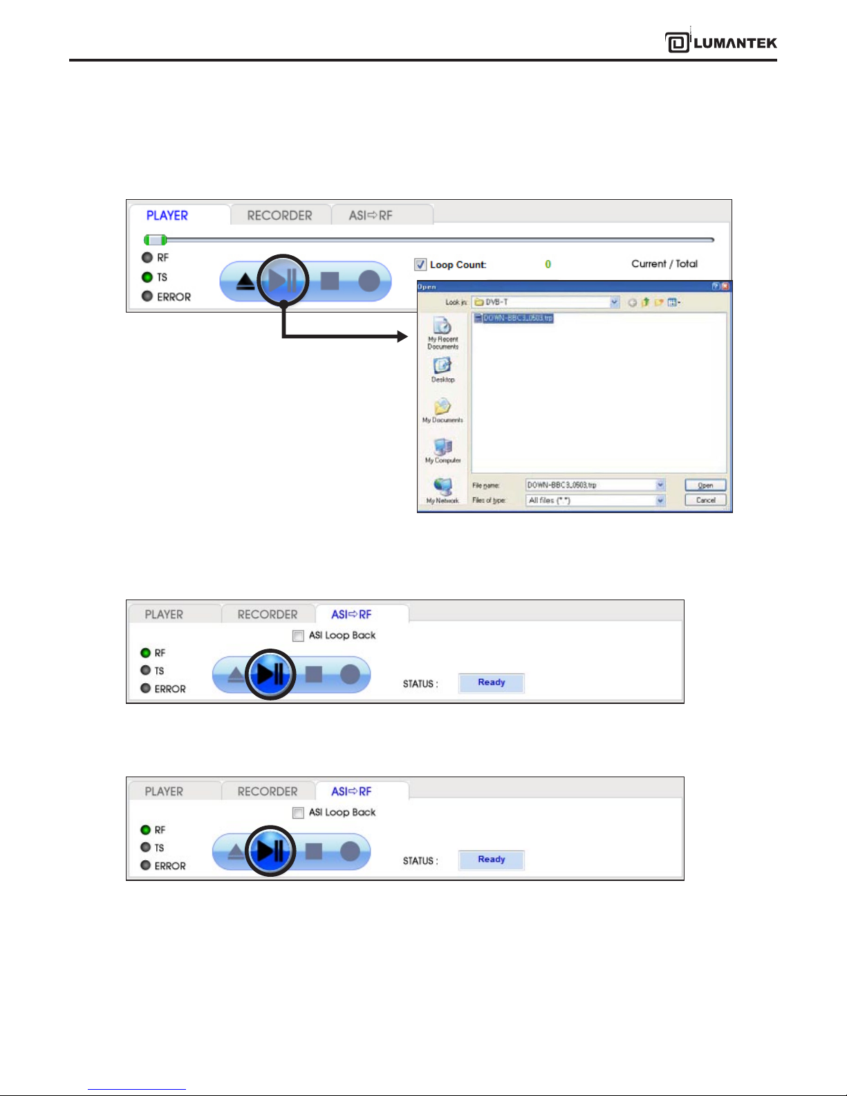
5. When you want to transmit ASI Input Signal as RF, go to [ASI->RF] tab. Then you can Select RF-OUT Modulation.
- ASI Loop Back
- ASI Loop Back
- ASI Loop Back
Detail View of RECODER tab
24
VENTUS 2.0 Manual / Updated 2013/2/15/ Operational Manual
VENTUS 2.0
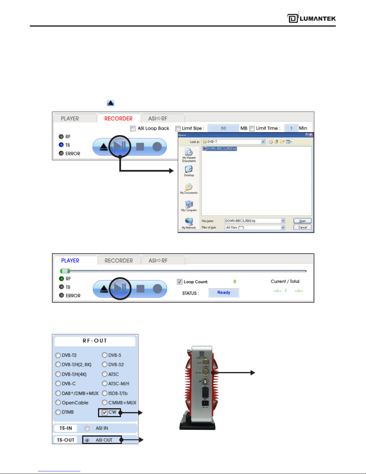
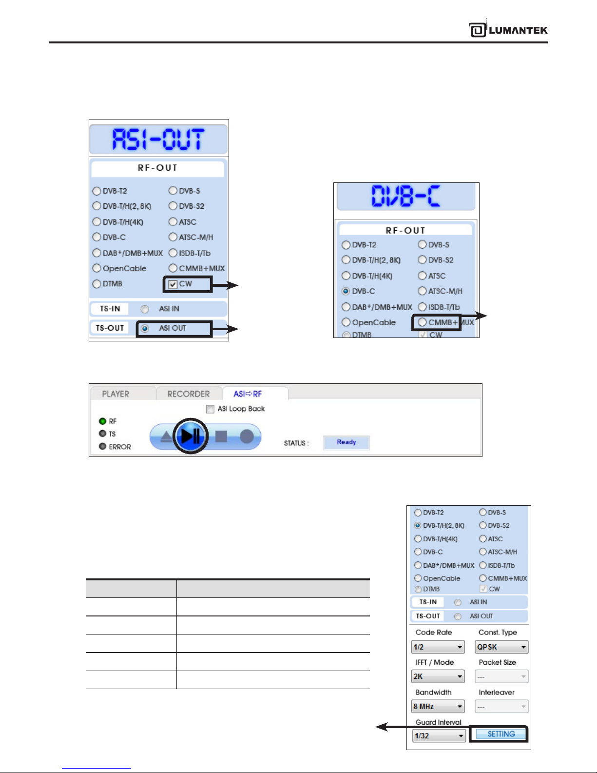
4.2 / TS-OUT Option : ASI Output
4.3 / RF Output option : CW
1. ASI Output is for transmitting the saved le [*.trp, *.tp] through ASI Output Port.
2. Top Left Menu in T-pump will change ASI-OUT when select TS-OUT option.
3. Click le open button( ) and select *.trp or *.tp to do ASI Out.
4. T-pump displays Stream le analysis per Program or PID. Status is Ready on PLAYER tab.
1. To use CW mode, rst you have to check
CW under ASI-OUT. It is NOT able to check-
ing CW option under RF-OUT.
Check CW
Check ASI OUT
ASI Output Port
25
VENTUS 2.0 Manual / Updated 2013/2/15/ Operational Manual
VENTUS 2.0
2. Select Modulation Option in RF-OUT menu, then CW option will active.
3. Select Modulation Option in RF->OUT menu, then CW option will active.
4. Move from [PLAY ] to [ASI->RF] tab, then click play button. It will transmit as CW.
26
VENTUS 2.0 Manual / Updated 2013/2/15/ Operational Manual
VENTUS 2.0
1. To use CW mode, rst you have to check CW under ASI-OUT. It is NOT
able to checking CW option under RF-OUT.
1. DVB-T/H option is divided by 2, 8k and 4k. Select suitable option for you.
Select DVB-T/H (2, 8K) on the top left of RF OUT menu in T-pump, DVB-T will
be shown.
Items Value
Code Rate 1/2, 2/3, 3/4, 5/6, 7/8
Const. Type QPSK, 16 QAM, 64 QAM
IFFT 2K, 8K, 4k
Bandwidth 5, 6, 7, 8 MHz
Guard Interval 1/32, 1/16, 1/8, 1/4
2. Select Modulation Option in RF-OUT menu, then CW option will active.
3. Move from [PLAY ] to [ASI->RF] tab, then click play button. It will transmit as CW.
Check CW
Check ASI OUT
4.4 / RF Output option : CW Operation
4.5 / RF Output Option : DVB-T/H(2, 8K)
Check CW
• DVB-T Parameter Value
Do not use under DVB-T/H(2, 8k) option
(Only for DVB-T/H(4k))
27
VENTUS 2.0 Manual / Updated 2013/2/15/ Operational Manual
VENTUS 2.0
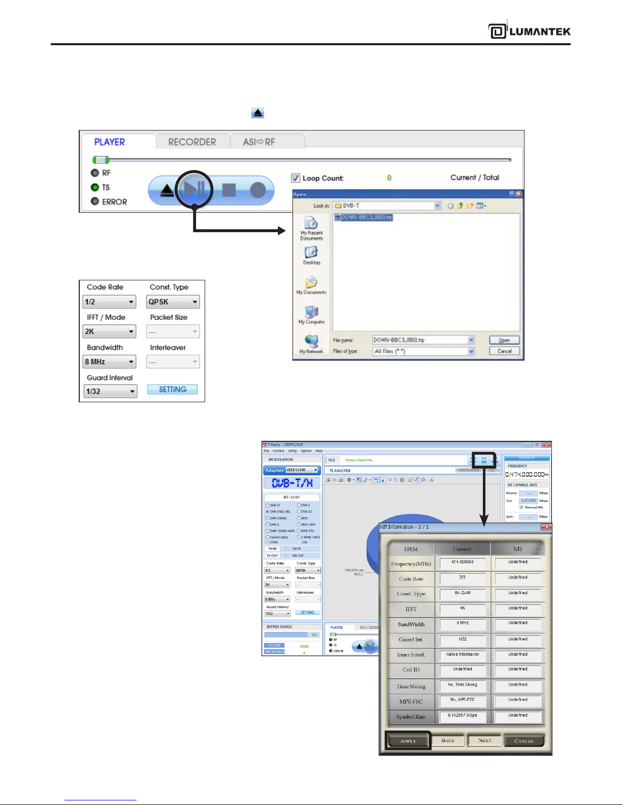
2. Select DVB-T option, Click le open button( ) and select [*.trp or *.tp] to do RF Output test.
3. Once you’ve selected a le, you can set RF Parameter as you need.
4. If you have information to the multi-NIT
with 2.4.0 version, you can check RF param-
eter. Like the picture below, if you click From
File bottom, you will get ts le’s NIT
information. After, Click [Apply], automati-
cally set all the options.
28
VENTUS 2.0 Manual / Updated 2013/2/15/ Operational Manual
VENTUS 2.0
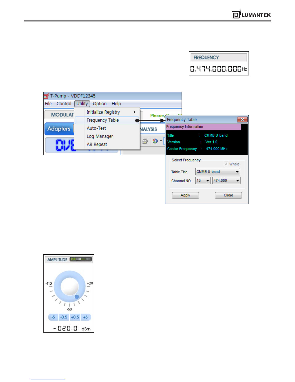
5. After select a stream le, set frequency under OUTPUT menu.
* You can set frequency by direct keyboard input
A sample *.dat le will give Frequency Table information. Create a sample le and save in [C:\Program Files\(C)
LUMANTEK\T-pump\FreqTable] folder. Now you can search on the frequency table window if you save it at.
6. When you use AMP & Attenuator, you must click [ON] on the amplitude window.
Power level changes between +7 dBm(+3dbm over frequency of 1GHz) ~ -110 dBm
per 0.5dB step by Jog Shuttle or per 0.1dB by keyboard input.
* Maximum level is +7dBm under the frequency range of 1GHz or less
Maximum level is +3dBm from the frequency range of 1GHz or more
* Or by [Frequency Table] under [Utility[ menu.
29
VENTUS 2.0 Manual / Updated 2013/2/15/ Operational Manual
VENTUS 2.0
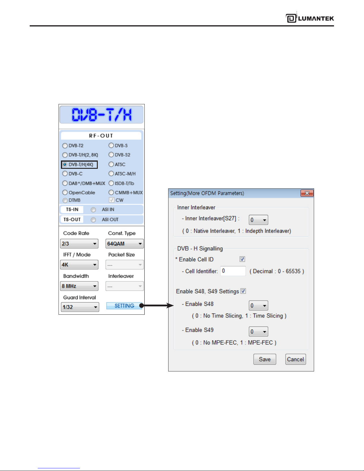
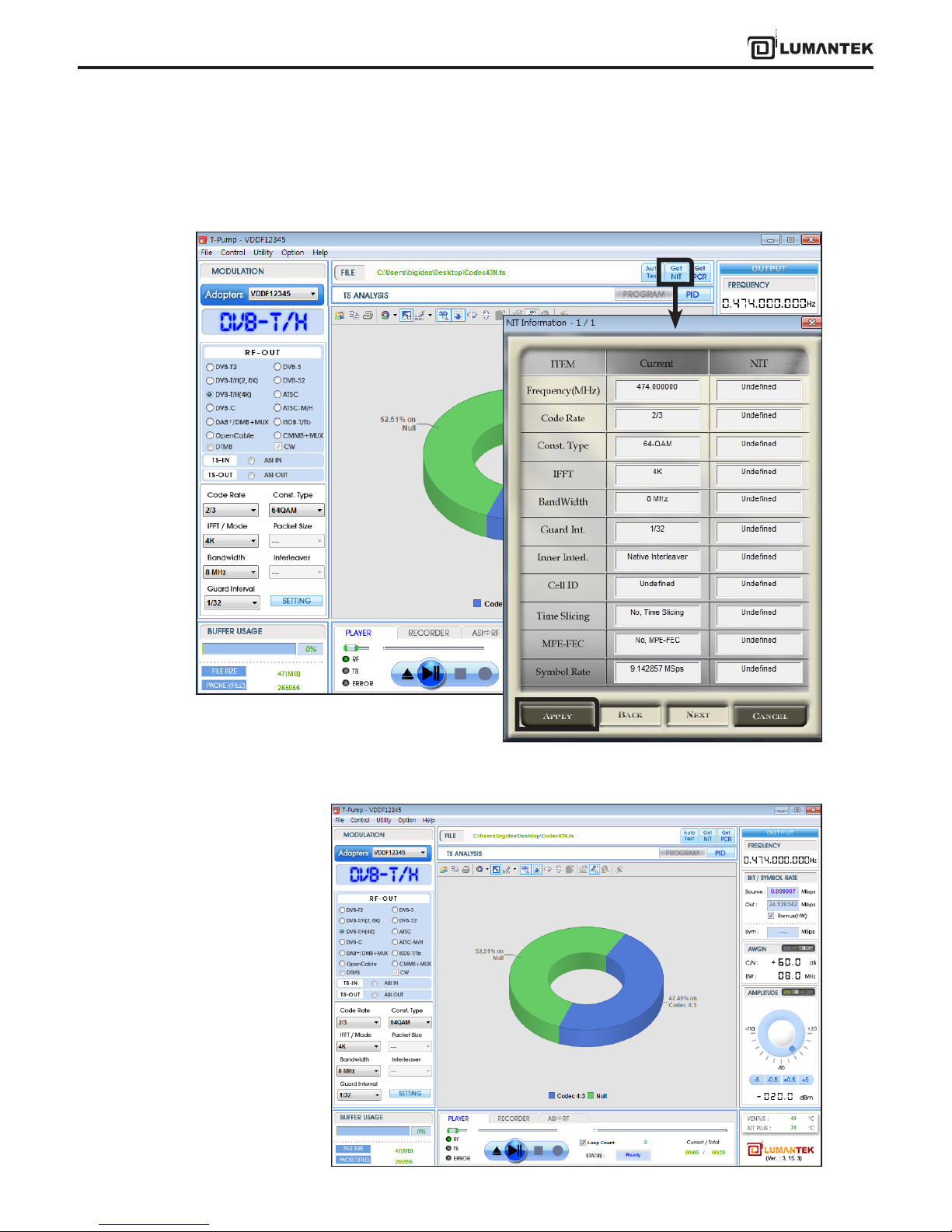
1. When you select DVB-T/H(4K), DVB-T/H will appear on display window.
2. Click [SETTING] button and set like below image.
- Inner Interleaver [S27] : 0 (Native Interleaver)
- DVB-H Signaling
- Select Enable Cell ID
- Cell Identier : Input suitable stream le Cell ID.(0~65535)
- Select Enable S48, S49 Setting
- Enable Cell ID S48 : 1 (Time Slicing)
- Enable Cell ID S49 : 1 (MPE-FEC)
* Above setting is only for a sample stream le. Thus you can change options as you need.
4.6 / RF Output Option : DVB-T/H(4K)
30
VENTUS 2.0 Manual / Updated 2013/2/15/ Operational Manual
VENTUS 2.0
3. T-pump Ver 2.2.0 updated as you could check NIT information. Click [From File] in[BIT/ SYMBOL RATE] box, then
check the information of an opened *.ts le like below images. Click [Apply], automatically set all the options.
4. Rest of process is same as DVB-T/H(2K, 8K) operating.
 Loading...