


ez-Line VM16 / Manual
Updated July. 2016
manual
ez-LINE VM16 FullHD 16x16 Matrix Router
(SD/HD/3G-SDI)
By LUMANTEK

ez-Line VM16 : Manual
ez-Line Manual
Revision Number: 1.2.3
Distribution Date: July. 2016
Copy Rights
Copyright © 2006~2015 LUMANTEK Co., Ltd.
All Rights Reserved
This document contains information that is proprietary to LUMANTEK.CO., LTD. The information in this
document is believed to be accurate and reliable; however, LUMANTEK assumes no responsibility or liability
for any errors or inaccuracies that may appear in this document, nor for any infringements of patents or other
rights to third parties resulting from its use.
This publication may contain technical issues, inaccurate information or typos. These will be revised in revised
edition, if there is any. No part of this publication is subject to be reproduced, stored in retrieval system, or
transmitted in any forms, or any means without the prior consent by Lumantek.
Trademarks
HD ENCODULATOR
PlusTM, Media BlasterTM, are Trademarks of Lumantek. Co., Ltd.
Any other trademarks than stated above in this document belongs to its pertinent corporation.
Warranty Period
Lumantek’s products comes with One(1) year limited warranty. Please contact below if you need more
information.
LUMANTEK CUSTOMER SERVICES
sales@lumantek.co.kr / TEL(Dir) : +82-2-6947-7429 / FAX: +82-2-6947-7440
TM
, SD ENCODULATOR
TM
LUMANTEK Logo, Mega CruiserTM, ORIXTM, X-CruiserTM, DTA-
2

ez-Line VM16 : Manual
Installation Precautions
This page states the safety measures the users must take to avoid circumstances where the system may
occur physical damages or injuries. Please THOROUGHLY go over this page before the system
installation/operation.
General Precautions
- Maintain dust FREE condition during and after System Installation/Operation.
- Please place the system cover in a safe location when opened.
- Securely stow tools and cables away from the passages.
- Avoid wearing loosened clothes or accessories during installation/Operation.
- Avoid any unnecessary actions that may damage/harm system or personnel.
Do NOT open the system unless advised by Lumantek representative. Lumantek takes no responsibility
on units with broken RMA seals.
Power Precautions
- Please check cable overload before connecting the system to the power supply.
- Avoid wearing metal accessories (Rings, Earrings) connecting system to the power source.
Avoid operating on wet floors. Make sure power extension cables, floors, and instruments are
grounded and in a safe operating condition.
- Please discharge static electricity by touching grounding metals before starting hardware installation.
- The grounding parts must be disassembled last.
- Manufacture takes no responsibilities on Direct/Indirect losses or damages due to use of
inappropriate parts or services by unauthorized service provider
- Supplying power during the system installation may cause damages to the system and personnel.
AC Power Precautions
- This unit utilizes AC power, the cord comes with a grounding function.
- Please connect the system to the power socket with groundings.
- Use Green/Yellow 0.75mm2 (18AWG) or higher grade grounding cables.
- Do NOT block power sockets with tools or boxes. Please keep it clear at all times.
3

ez-Line VM16 : Manual
Contents
1. Introduction ------------------------------
2. VM16 System Information ---------------
2.1 VM16 Main Frame Interface -----------
2.2 VM16 RCP Interface ---------------------
2.3 Product Components -------------------
2.4 System Operation -----------------------
3. Specifications -----------------------------
4. Communication Protocol ----------------
4.1 Transport Packet Structure.--------------
4.2 Transport Procedure---------------------
4.3 Parameter List ---------------------------
4.4 Command List ------------------------
4.5 Response/ Notification List ------------
5
6
6
7
8
9
15
16
16
16
17
18
19
5. Appendix --------------------------------
20
4
ez-Line VM16 : Manual
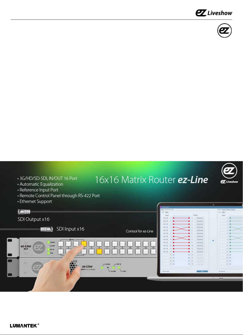
1. VM16 (FullHD 16x16 Matrix Router) Introduction
ez-line (VM16) is a SDI Matrix Router which support SD/HD/3G-SDI. it consists of 16 Input and
16 Output Ports. This equipment can be controlled with USBS 2.0, RS422, Ethernet port via the
communication protocol. Additional S/W is provided to control VM16 via USB2.0, RS422 and
Ethernet. Moreover, RS422 communication protocol to support RCP(Remote Control Panel).
• Features
① Supports SD/HD/3G-SDI
② Video IN/OUT Port (IN 16, OUT 16 / BNC Connector)
③ Supports Reference Input Port (B.B , Tri-Level)
④ Supports USB2.0, RS422, Ethernet Port
⑤ Provides simple S/W UI for PC
5
ez-Line VM16 : Manual
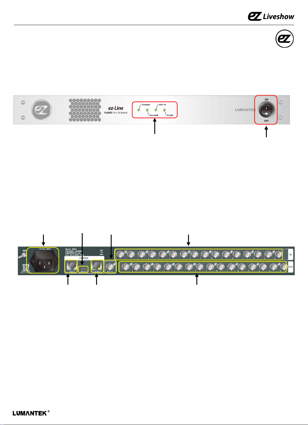
2. VM16 Interface
2.1 VM16 Main Frame Interface
< Front >
① Status LED
① LED Status
- POWER : Indication of power input, Green light indicates power on.
- ALARM : Red light will turned on if there is error on internal communication.
- REF IN : Green light will turn on when Reference input is detected.
- COM : Green light will flash when it is controlled by RS422 and Ethernet Port.
② Power Switch : AC Power ON/OFF Switch
⑤ UPDATE
⑦ REF IN
⑧ SDI IN ③ AC Power
< Rear>
② Power Switch
④ RS422
⑥ ETHERNET
⑨ SDI OUT
③ AC Power : AC Power input (100 -240V, 50/60Hz)
④ RS422 : RS422 communication Port for RCP and UI. communication protocol control (RJ45)
⑤ UPDATE : USB Port for UI. communication protocol control and firmware UPDATE (Micro USB)
⑥ ETHERNET : ETHERNET port. UI and communication protocol control (RJ45)
⑦ REF IN : Reference port. Support Black Burst, Tri-level (BNC Connector)
⑧ SDI IN : consist of 16 video input port (BNC Connector)
⑨ SDI OUT : consist of 16 video output port (BNC Connector)
6

ez-Line VM16 : Manual
2.2 VM16 RCP Interface
① Status LED
< Front >
② SDI IN
③ SDI OUT
④ SHIFT
⑤ PANEL Lock
⑥ LOAD/SAVE
① Status LED
- POWER : Green light will turned on when the power is on.
- ALARM : Red light will turned on if there is error on internal communication.
- REF IN : Green light will turn on when Reference input is detected.
- COM : Green light will flash when it is control by RS422 and Ethernet Port.
② SDI IN : 16 SDI Input control buttons.
③ SDI OUT : 16 SDI Out control buttons.
④ SHIFT : Use SHIFT button, if SDI input ports are more than 16 ( Max in/output 32 port)
⑤ PANEL Lock : PANEL Lock button (LED ON : Panel Locked, LED OFF Status : Panel Unlocked )
⑥ LOAD/SAVE : When this button is pressed, 4 input and output buttons will turned on. 4 input
button to saving the configuration and output button for load the configuration.
① RS422
① RS422 : RS422 Communication Port
< Rear >
7

ez-Line VM16 : Manual
2.3 Product Components
- Basic Components
① VM16 Main Frame
② POWER CABLE
- Optional RCP
① Remote Control Panel
8

ez-Line VM16 : Manual
2.4 Product Operation
1) UI connection using RS422 or USB2.0 Communication
① Run EXE file -double click on “ “
② Select RS422 Tab ③ PC COM recognition. Disabled if recognition failed.
④ Press “Connect”
⑤ Device Information and Network Setting will be updated when communication is connected.
9

ez-Line VM16 : Manual
2) UI connection using Ethernet Communication
① Run EXE file -double click on “ “
② Select Ethernet Tab.
③ Setting for default IP address.
④ Press “Connect”
⑤ Device Information and Network Setting will be updated when communication is connected.
10

ez-Line VM16 : Manual
⑥ Communication failure lead to “No response from device” message on screen.
Connect through RS422 communication check IP address and change to desired IP
address.
3) Changing IP address using RS422 Communication..
① Run EXE file -double click on “ “
② Select RS422 Tab ③ PC COM recognition. Disabled if recognition failed.
④ Select Connect button
⑤ Enter the desirable IP address
eg) 192.168.10.191
⑥ Press Apply button
⑦ IP address has been change to
192.168.10.191
11

ez-Line VM16 : Manual
4) Setting for Input/Output S/W UI
① Using RS422 or Ethernet communication, connect to device UI.
② Select Current In-out Link Tab.
③ Input/Output setting is set by dragging mouse from input to output or output to input.
④ Input window displays the signal information. X will display on the box If there is no signal input.
⑤ If user click ‘Auto apply‘ box , any changes on input/output setting will be applied immediately.
⑥ if user left ‘Auto apply‘ box unchecked , then user must press ‘ Apply’ button manually after
changing input/output setting to apply it.
②
③
④
⑤
⑦ Can use this device as a SDI distributor, set a single input to multiple outputs.
⑥
⑦
12

ez-Line VM16 : Manual
5) Load and Save feature for input/output settings
① Use RS422 or Ethernet communication to connect the equipment and S/W UI
② Support up to 4 Preset settings. (below showing Preset 0 setting)
③ Input/output setting is set by dragging mouse from input to output or output to input.
④ When you press ‘Save’ button ,the setting will be saved on Preset 0 , but current input and
output is not applied. (if ‘Auto save’ box is clicked then the setting is saved automatically)
⑤ Current input/output settings.
⑤
②
③
⑥ Click arrow button to apply Preset 0 Setting to current setting.
④
⑥
13

ez-Line VM16 : Manual
6) RCP Connection Using RS422 or Update Port
① VM16 Main Frame RS422 setting
② VM16 RCP (Remote Control Panel RS422 setting
③ VM16 Main Frame and RCP are connected by Direct Cable.
14

ez-Line VM16 : Manual
3. Specification
Data Input
SDI Video Input: SD/HD/3G-SDI (BNC 75Ω) x16
Reference Input: B.B , TRI (BNC 75Ω) x1
Data Output
SDI Video Input: SD/HD/3G-SDI (BNC 75Ω) x16
Connections
Remote Control: RS-422 (RJ45)x1
Ethernet: Ethernet Support (RJ45)x1
Update: Debug (Micro-USB)x1
Electrical
Power Input: 100~240VAC @ 50/60Hz
Power Consumption: 18W(max.)
Operation Temperature: 0~40℃
Physical
Dimension: 44(H) X 483(W) X 240(D)
Weight: 2.0 kg
15

ez-Line VM16 : Manual
4. Communication Protocol
4.1 Transmission Packet Structure
▶ It can communicated with common serial terminal software and Command based
communication, also using checksum to allow error detection.
Index
Header
#(0x23)
$(0x24)
▶ Index Header: Command and Response ‘#’, Notification ‘$’. If command line does not
Index Space Command/
Response/
Notification
0~
65535
‘ ‘
(0x20)
_ ` a~z
(0x5F~0x7A)
Space Parameters Space Check
sum
‘ ‘
(0x20)
0~9
(0x30~0x39)
‘ ‘(0x20)
‘ ‘
(0x20)
A~P
(0x41~
0x50)
Carriage
Return
‘/r’
(0x0D)
start with #, it will consider to not having Index.
▶ Index: Command Response Notification indexing number (10) decimal 1~5 digits
(0~65535)
▶ Command/Response/Notification: ASCII code consist of 2 special characters and small
letters, between 0x5F~0x7A, See Command and Response/Notification list
▶ Parameter: determined by number of Command/Response/Notification, each parameter
is separated by space
▶ Checksum: displayed in hexadecimal with capital A~P. Add byte from Index header to
Checksum in 2 byte size. expressed in 4 digits hexadecimal. Simplified hexadecimal so that
doesn’t use (0~9)(A~F). Use continues A~P , take 4 bits from each checksum byte and
add A to convert it. (see Appendix 1 -example)
▶ Carriage Return: ‘/r’ text sent as a packet terminal indication, see Terminal settings.
4.2 Transfer Procedure
▶ Transferring side: Command
▶ Reception Side: Reception Command/ execution and then transfer /execution results
Response
▶ After sending Command if there is no response for 10ms, then Time-Out.
▶ Time-Out or er r or responses, 3 times further repeated t r ansfer and then give up. Communication
error .
▶ Notification is sent t o indicate a state changes from device t o t he host .
16

ez-Line VM16 : Manual
4.3 Parameter List
# Input Channel Category 0: SDI Input 1
Category Parameter List
1: SDI Input 2
2: SDI Input 3
3: SDI Input 4
4: SDI Input 5
5: SDI Input 6
6: SDI Input 7
7: SDI Input 8
8: SDI Input 9
9: SDI Input 10
10: SDI Input 11
11: SDI Input 12
12: SDI Input 13
13: SDI Input 14
14: SDI Input 15
15: SDI Input 16
31: No Connect
# Output Channel Category 0: SDI Output 1
1: SDI Output 2
2: SDI Output 3
3: SDI Output 4
4: SDI Output 5
5: SDI Output 6
6: SDI Output 7
7: SDI Output 8
8: SDI Output 9
9: SDI Output 10
10: SDI Output 11
11: SDI Output 12
12: SDI Output 13
13: SDI Output 14
14: SDI Output 15
15: SDI Output 16
# Preset Category 0: Preset 1
1: Preset 2
2: Preset 3
3: Preset 4
# Loss Category 0: Signal is not loss
1: Signal is loss
17

ez-Line VM16 : Manual
4.4 Command List
Command NOP Description
set_cfg_all 16
get_cfg_all 0
set_cfg_one 2
get_cfg_one 1
get_inloss_all 0
get_inloss_one 1
set_ipaddr 4
get_ipaddr 0
set_subnetmask 4
get_subnetmask 0
set_gateway 4
get_gateway 0
set_port 1
get_port 0
get_macaddr 0
set_default 0
get_refinled 0
set_save_preset0 16
get_preset0 0
set_save_preset1 16
get_preset1 0
set_save_preset2 16
get_preset2 0
set_save_preset3 16
get_preset3 0
set_apply_preset 1
Set command for 16 outport associated 16 inport
Param1~Param16, refer to Input Channel List
Get command for 16 outport associated 16 inport
Set command for specified 1 outport associated 1 inport
Param1: see Output Channel List
Param2: see Input Channel List
Get command for specified 1 outport associated 1inport
Param1: see Output Channel List
Get command for 16 inport associated Loss [off/on] information
Get command for specified 1 inport signal Loss [off/on] information
Param1: See Input Channel List
command to set for IP address
command to get the IP address
command to set subnet mask
command to get the subnet mask
Command to set the default gateway
Command to get the default gateway
Command to set the port number
Command to get the port number
Command to get the Mac address
Load to default value and save to EEPROM
Command to get REF IN LED on/off status
Command to save 16 outport associated with 16 inport information
on to EEPROM(Preset)
Param1: See Input Channel List
Command to get 16 outport associated with 16 inport information
(Preset)
Command to save 16 outport associated with 16 inport information
on EEPROM (Preset)
Param1: See Input Channel List
Command to get 16 outport associated with 16 inport (Preset)
Command to save 16 outport associated with 16 inport on EEPROM (Preset)
Param1: See Input Channel List
Command to get 16 outport associated with 16 inport information
(Preset)
Command to save 16 outport associated with 16 inport information on EEPROM (
Preset)
Param1: See Input Channel List
Command to get 16 outport associated with 16 inport information
(Preset)
Command to read and apply from Preset 0/1/2/3 EEPROM
Param1: See Preset List
get_rcpll 0
checksum_en 0
checksum_dis 0
get_model 0
get_ver 0
Command to get the information of RCP Lock LED Off/On
Enable checksum
Disable checksum
Model Name output
Version information output
18

ez-Line VM16 : Manual
4.5 Response/ Notification List
Response/
Notification
NOD Description
ok 0 Communication success
error_too_short 0 Communication failure: checksum digit is short
error_bad_checksum 0
Communication failure: checksum parameter is not right,
checksum digit is too long.
error_checksum 0 Communication failure: checksum value is not right
error_invalid_param 0 Communication failure: invalid parameter
error_invalid_comman
d
state_model 1
Communication failure: invalid command
0
Model name output
Data1: Model name (VM16, VS6, VM6, VM4,…)
Version information
state_ver 3
Data1: Major Version
Data2: Minor Version
Data3: Revision
state_cfg_all 16
Information status of 16 outport associated 16 inport
Data1 ~ Data16 : See Input Channel List
Information status of specified 1 outport
state_cfg_one 2
Data1: See Output Channel List
Data2: See Input Channel List
state_inloss_all 16
Information status of Signal Loss [off/on] for 16 inport
Data1 ~ Data16: See Loss List
Information status of signal Loss [off/on] for specified inport
state_inloss_one 2
Data1: Input Channel loss List
Data2: See Loss List
state_ipaddr 4
state_subnetmask 4
state_gateway 4
state_port 1
state_macaddr 6
state_refinled 1
state_preset0 16
state_preset1 16
state_preset2 16
state_preset3 16
state_rcpll 1
IP address status
Data1~ Data4 : IP address
Subnet mask status
Data1~ Data4 : Subnet mask address
Gateway status
Data1~ Data4 : Gateway address
Port number status
Data1: Port number
Mac address status
Data1~ Data6 : Mac address
REF IN LED status
Data1: 0/1 = led off/led on
Information status for 16 outport associated with 16 inport
(preset)
Data1 ~ Data16 : See Input Channel List
Information status for 16 outport associated with 16 inport
(preset)
Data1 ~ Data16 : See Input Channel List
Information status for 16 outport associated with 16 inport
(preset)
Data1 ~ Data16 : See Input Channel List
Information status for 16 outport associated with 16 inport
(preset)
Data1 ~ Data16 : See Input Channel List
RCP Lock Led status [0/1=off/on], 0 respresent RCP controling
Data1: 0/1 = led off/led on
19

ez-Line VM16 : Manual
99
95
32
5. Appendix
Appendix A
checksum_dis AFBC
c h e c k s u m _ d i s
10
10
99
4
Decimal : 1298 = hexadecimal 0x0512
0 + A = A
5 + A = F
1 + A = B
2 + A = C
1
107
11
11
10
5
7
10
9
0
105
11
tot
al
129
he
x
05
0 5 1 2
8
12
5
che
cks
um
A F B C
20
 Loading...