

Page 1

700 Series Bullet
500 Series Bullet
HD Analog Surveillance Camera
Installation &
Operation
Manual
Page 2
2
Luma 500/700 Series Bullet Camera
Installation
Before you start, ensure that the device is in good condition and all the assembly parts are included.
We recommend installing with RG-59 or RG-6 cabling with two-wire power (either regular or siamese). This
provides better performance over distance than using traditional category cable with baluns. For more details, see
the product page at SnapAV.com.
} Make sure that all equipment is powered off during installation.
} Ensure the wall is strong enough to withstand three times the weight of the camera and the mount.
} If the mounting surface is cement, use the included expansion screws to install the camera. If mounting to
a wood surface, use self-tapping wood screws (not included) to secure the camera.
} If the product does not function properly, please contact technical support. Do not disassemble the camera
for repair or maintenance.
Box Contents
} Camera
} Self-adhesive mounting template
} 4 x wall anchors with screws
} 3mm hex wrench
} CC tester cable
Page 3
3
Luma 500/700 Series Bullet Camera
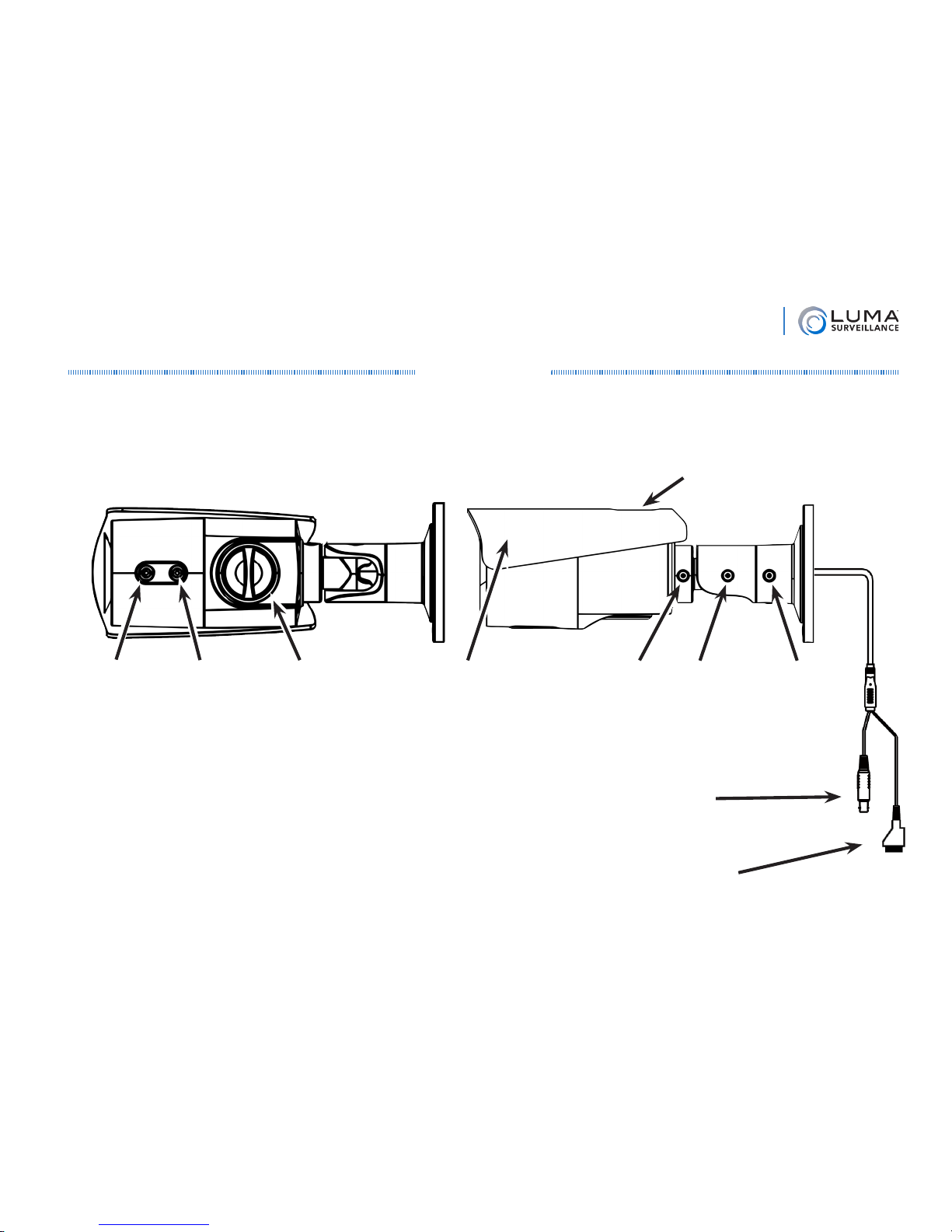
Overview
Before installing, familiarize yourself with the parts of your camera.
Required Equipment
Aside from the contents of this box, you will need to provide
} Phillips screwdriver
} Power source: either 12V DC or 24V AC
} CC-TV tester (recommended)
Focus Dial Zoom Dial Access Panel
Sunshade
Adjustment
Screw
(not visible)
Sunshade Level
Screw
C
Elbow
Screw
A
Power Cable
CVBS / HD-TVI
BNC Cable
Base
Screw
B
Page 4
4
Luma 500/700 Series Bullet Camera
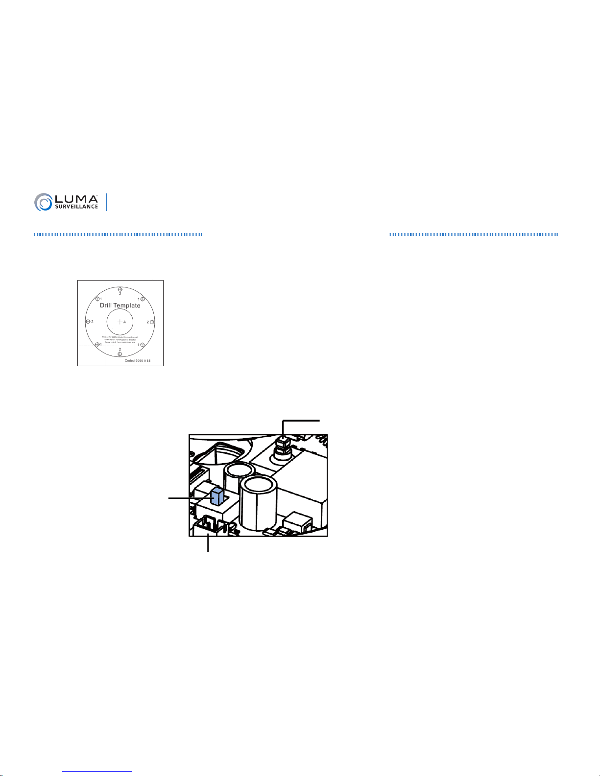
Prepare for Installation
1. Drill a cable hole and pilot holes for your screws in the ceiling, using the supplied template.
2. If you are installing this camera in an older system that does not support HD-TVI, unscrew the access panel cap
and flip the camera’s resolution toggle, shown below, to the CVBS position.
Joystick
Video/Power Test Port
Resolution
Toggle
Page 5
5
Luma 500/700 Series Bullet Camera
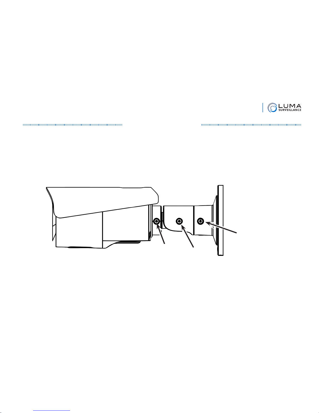
Install the Camera
3. Attach the base of the camera to the ceiling and secure it with screws.
4. Route the cables through the cable hole.
5. This camera has an elbow joint flanked by two rotational joints for perfect pan and tilt control. Loosen
the three hex screws in the camera. Adjust the angle of the elbow as desired, and tighten the elbow
hex screw, A. Rotate the camera so that it’s facing in the proper direction, and tighten the base screw,
B. Finally, spin the camera casing so that the picture is level, and tighten the level hex screw, C.
6. Connect the power and video cables.
7. Optional: If this is an HD installation and you want to use the camera’s on-screen display through your
DVR or the web interface, go into the DVR’s menu and set the camera protocol to HIK-C (Coaxitron). To
do so from the DVR’s local interface, go to Settings > Camera > PTZ, then click the PTZ Settings button.
From the web interface, go to Configure the Recorder > Camera Settings > PTZ Settings. If this is a 960H
installation, you can only use the OSD menu locally at the camera.
Level
Screw
C
Elbow
Screw
A
Base
Screw
B
Page 6
6
Luma 500/700 Series Bullet Camera
Adjust the Camera
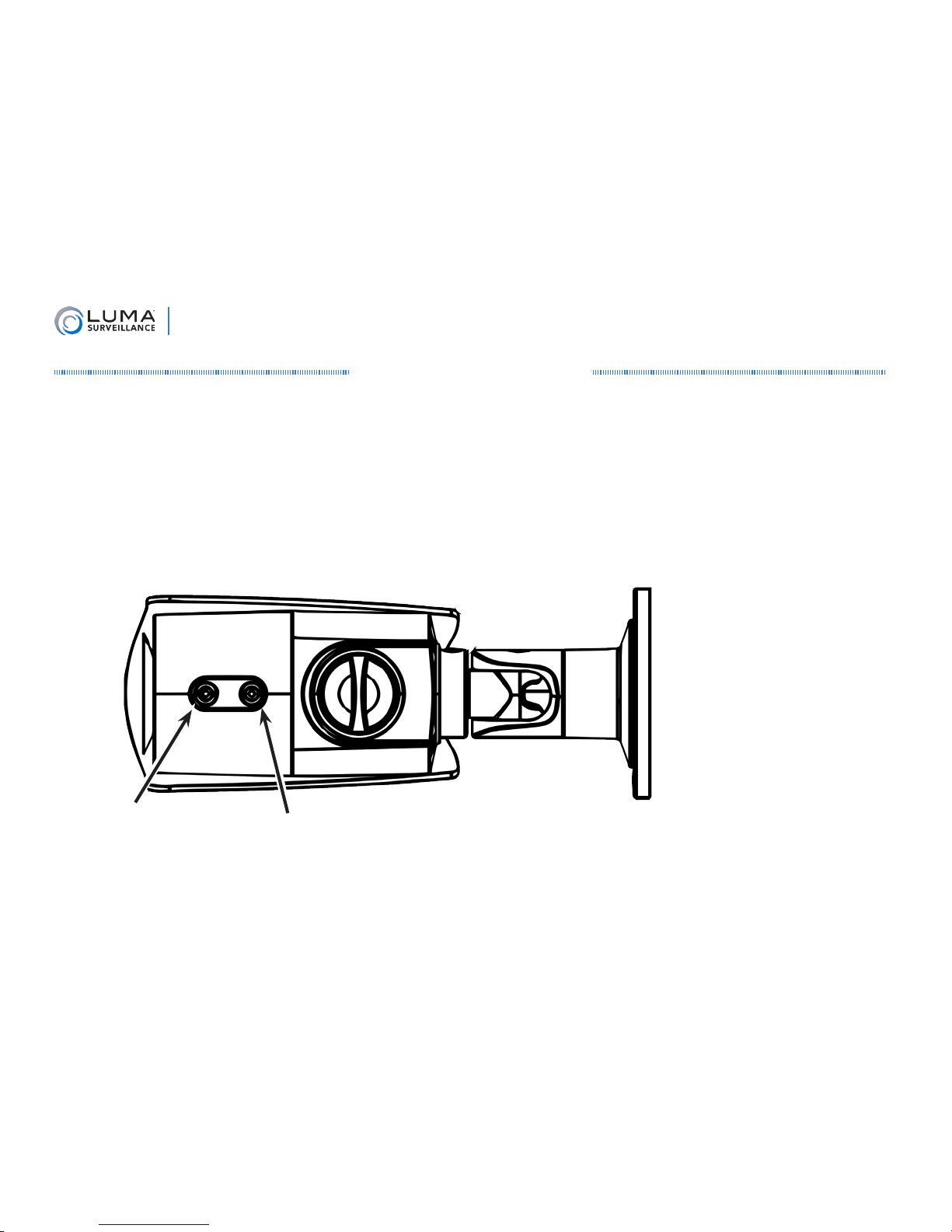
1. Adjust or remove the sunshade. You can slide the shade back and forth by loosening the screw slightly;
tighten when finished. You can remove the shade by removing the screw, then removing the shade; then
replacing the screw when finished.
2. Adjust the camera’s zoom and focus by adjusting the dials at the front of the camera using a screwdriver.
On the front (focus) screw, F and N stand for far and near, respectively. On the rear (zoom) screw, T and W
stand for wide angle and telephoto.
3. If you want to adjust the camera settings using a CC tester, do that now (see page 9). Otherwise, you’ll use
the DVR’s controls to adjust the camera settings.
Clockwise: wide-angle
Counterclockwise: telephoto
Clockwise: focus near
Counterclockwise: focus far
Page 7

7
Luma 500/700 Series Bullet Camera
Menu Operation
The in-camera menu is structured as follows:
Smart
Focus
Video Out Language
Setup
Scene Lens Exposure Backlight
White
Balance
Day &
Night
NR Special Adjust Reset Exit
Indoor Shutter WDR ATW Ext 2DNR
Camera
Title
Sharp-
ness
Factory
Outdoor AGC BLC AWC-Set Color 3DNR D-Effect Monitor
Indoor1
Sense-Up
(700 only)
HSBLC Manual
Black &
White
Motion LSC
LowLight
Bright-
ness
Privacy
True
WDR
Defect
Defog
MENU
Page 8

8
Luma 500/700 Series Bullet Camera
Main Menu Items
The DVR’s control interface can handle camera functions, or you can access the camera’s internal menu directly.
To access the camera menu through the DVR’s local interface, click the PTZ ( ) icon on the live page, then click
the menu ( ) button in the configuration bar of the control panel. Over the web, click PTZ ( ), scroll down
to Preset 95, and press the call icon. The camera’s internal menu shows up on screen, and you can use the PTZ
controls make your choices.
Throughout the menus, the up and down arrows move among the menu choices, and the left and right arrows
switch between options for that choice. The 8 symbol indicates that pressing Iris+ opens a submenu in which
you can set parameters of that menu item. (When inside the camera, the joystick moves the selection, while
pressing the joystick like a button selects the item.)
To exit the menu system, go to Setup > Exit. From deep within the menu, you can click the right arrow while
Return is selected; then, when you press Iris+, the menu closes instead of sending you back one level. The menu
also closes after a few minutes of inactivity.
Video Out
Use the arrows to send the video signal in PAL or NTSC format. North America uses NTSC.
Language
Use the arrows to select from English, French, Spanish, and many other languages. Click Iris+ to switch all menu
items to that language immediately.
Setup
Press Iris+ to open the submenu that controls the camera’s operations.
Page 9

9
Luma 500/700 Series Bullet Camera
Setup Menu Items
Smart Focus
Press Iris+ to have the camera test the view and make a recommended focus setting for varifocal lenses. It does
not adjust the camera’s focus to that number; you must do it manually. Note: This camera has a varifocal lens; its
focus can only be adjusted manually. Press Iris+ again to return to the menu.
Scene
Use the arrow buttons to set the camera’s working environment to indoor, outdoor, indoor 1 (which includes
backlight compensation), or low-light. Test the various options to find which works best for your needs.
Lens
The camera is equipped with a fixed-length lens, so this menu option cannot be changed.
Exposure
Press Iris+ to adjust the parameters below.
Shutter
This adjusts the shutter speed for the camera. Most shutter speeds are given in a fraction of a second. Slower
shutter speeds (e.g., 1/25) increase the amount of light to the image sensor but also increase movement blur;
higher values decrease the amount of light to the image sensor but provide sharper captures of moving objects.
You can also select auto (the camera determines the best speed), or FLK (the shutter changes between 50Hz and
60Hz to reduce flickering).
Page 10

10
Luma 500/700 Series Bullet Camera
AGC
Use the arrows to set the automatic gain control value from 0 (making the image darker in bright areas) to 15
(making the image brighter in dim areas).
Sense-Up (700 Series Only)
This grants your camera the ability to generate a color image at night by using ambient light. If the shutter is set to
auto or 1/25, you can enable sens-up. When sens-up is enabled, the camera slows shutter time in low-light areas,
allowing more light into the lens. This provides color data, but may result in blurry images of moving objects. If
enabled, you can press Iris+ to specify sens-up settings.
Sense-Up: Set the sense-up ratio anywhere from x2 to x30.
Return: Press Iris+ to go back to the previous menu.
Brightness
Use the arrows to control the overall brightness of the image. Low values result in a darker image; high values give
a brighter image. Extreme values can result in loss of detail in dark or brightly lit areas.
True WDR (Enhanced Algorithms in the 700 Series)
Use the arrows to enable or disable true wide dynamic range. This sets the difference between dark and light
areas to maintain a higher quality image across all lighting conditions. We recommend you use this only if the
camera is viewing both very bright and dark areas (such as backlit windows).
Defog
Enable the defog function if desired. This grants the camera better visibility in foggy ambient conditions. It does
not affect condensation on the interior or exterior of the camera. Press Iris+ to set the parameters below.
Page 11

11
Luma 500/700 Series Bullet Camera
Position/Size: This option lets you use the defog effect on only a portion of the camera’s view. You first set the
location of the upper left-hand corner of the area (defog defaults to full screen, so the first time you use this,
you will not be able to move the area). Once it is positioned correctly, confirm your choice with Iris+. Next
adjust the size of the area by moving the lower right-hand corner. Confirm your choice when done. Finally,
Again lets you redefine the area, and Ret sends you back to the previous menu. Confirm with Iris+.
Gradation: When active, this determines how much fog you want to be visible. Lower values result in a stronger
defog effect; higher values are more true to the visibility.
Default: Press Iris+ to restore the default defog settings.
Return: Press Iris+ to go back to the previous menu.
Return
Press Iris+ to go back to the previous menu.
Backlight
Use the arrows to have your camera employ WDR, BLC, HSBLC, or none of the above (off). Press Iris+ to configure
that setting’s parameters, below.
WDR (Enhanced Algorithms in the 700 Series)
Wide Dynamic Range adjusts bright and dark areas. The more uniform lighting gives a better overall effect.
Gain: Select low, middle, or high. Higher gain values result in more lightening of dark areas.
WDR Bright: Set the brightness of the processed image as a whole.
WDR Offset: Use the arrows to adjust this. Higher numbers results in a brighter image overall.
Return: Press Iris+ to go back to the previous menu.
Page 12

12
Luma 500/700 Series Bullet Camera
BLC
Backlight compensation adjusts for areas where the backlight is strong. Its chief advantage is that you can apply it
primarily to a select portion of the camera’s view (although, to preserve a natural look, it influences the appearance
of the whole screen).
Gain: Set the gain to low (for areas with minimal backlight), middle, or high (for areas with lots of backlight).
Area: Press Iris+ to determine the area to which BLC is applied. You first set the location of the upper left-hand
corner of the area. Once it is positioned correctly, confirm your choice with Iris+. Next, adjust the size of the
area by moving the lower right-hand corner. Confirm your choice when done. Finally, Again lets you redefine
the area, and Ret sends you back to the previous menu. Confirm with Iris+.
Default: Press Iris+ to restore the camera’s default BLC settings.
Return: Press Iris+ to go back to the previous menu.
HSBLC
High-suppression backlight compensation adjusts for areas where the backlight is overpowering. This option acts
like BLC for the selected area(s) only, but with the advantage of masking out over-bright areas.
The camera has four areas for HSBLC. You can arrange these as you like either to mask out several lights, or to
create a custom shape for HSBLC processing.
Select: Press Iris+ to chose an area to edit. The selected area flashes on the screen.
Display: Choose whether or not to use that area. If the area is set to on, press Iris+ to edit the size and location
of that area. You first set the location of the upper left-hand corner of the area. Once it is positioned correctly,
confirm your choice with Iris+. Next adjust the size of the area by moving the lower right-hand corner.
Confirm your choice when done. Finally, Again lets you redefine the area, and Ret sends you back to the
previous menu. Confirm with Iris+.
Page 13

13
Luma 500/700 Series Bullet Camera
Level: Set the HSBLC level from 0 to 100; this determines how bright something must be for the camera to
apply HSBLC to it. Lower levels mean more of the camera screen is affected; higher levels mean that only the
brightest areas are affected. This setting applies to all HSBLC areas.
Mode: Select whether you want HSBLC active all day long, or only at night (as decided by the camera’s sensor).
Black Mask: When this is on, the camera covers the brightest areas with a black mask. This setting applies to
all HSBLC areas.
Default: Select this with the Iris+ button to restore the camera’s default HSBLC settings.
Return: Press Iris+ to go back to the previous menu.
White Balance
White balance corrects the colors of the image so that white actually appears white.
Use the arrows to select ATW, AWCSet, or manual. ATW (auto-tracking white balance) has the camera handle
white balance constantly, changing the amount based on conditions. AWCSet has the camera adjust the white
balance once, and then use that setting without further change.
If manual is selected, press Iris+ and use the arrows to adjust the blue and red levels (adjusting these determines
the green level). Select Return with Iris+ to go to the previous menu.
Day & Night
Use the arrows keys to select whether you want the camera to record in color, black and white, or use the camera’s
built-in external sensor (Ext) to decide which mode to use.
If you have chosen to use the exterior sensor, press Iris+ to set the infrared LED on or off with the arrow buttons.
Turning it on gives greater image lighting; turning it off reduces reflective glare. Select Return with Iris+ to go
back to the previous menu.
Page 14

14
Luma 500/700 Series Bullet Camera
NR (Enhanced Algorithms in the 700 Series)
To edit noise reduction settings, press Iris+.
2DNR
This uses image data alone to reduce noise. Use the arrow keys to turn this on or off.
3DNR
This uses image data as evaluated over time to reduce noise. Use the arrow keys to turn this on or off. If this is on,
press Iris+ to customize its settings.
Smart NR: This option applies noise reduction, but also allows you to press Iris+ to set sensitivity.
Level: Ranges from 0 to 100; the higher the level, the stronger the noise reduction.
Start AGC: The level at which the camera starts using automatic gain control.
End AGC: The level at which the camera ceases applying automatic gain control.
Return: Press Iris+ to go back to the previous menu.
Special
Press Iris+ to specify a number of assorted functions.
Camera Title
Use the arrow keys to decide whether you want custom text to appear on the channel screen. If so, click Iris+ to
create or edit the text that you want to appear.
Within the virtual keyboard, arrows move the cursor about, and Iris+ selects that letter or command. The camera
Page 15

15
Luma 500/700 Series Bullet Camera
legend is displayed at the bottom of the keyboard; the flashing underscore shows where the next letter will go
(overwriting any letter currently there).
The arrow icons shift the flashing underscore left and right. CLR erases all text. POS lets you position the text on
the screen using the arrow keys. END finishes your edits.
D-Effect
These digital effects enhance the operation of your camera. Press Iris+ to edit the choices below.
Freeze: Use the arrow keys to freeze the image on the camera. It remains frozen until you deselect this. Note that
the camera does not record while it is in freeze mode.
Mirror: If the image is not frozen, you can adjust how the image appears on the channel. Mirror reverses the
image right-to-left, V-flip reverses the image top-to-bottom, and Rotate spins the image 180° (and is thus suited
for cameras installed on top of a surface).
D-Zoom: This option let you zoom to an area of your choice. It is disabled if Smart D-Zoom is on. When this is
on, press Iris+ to adjust its settings.
D-Zoom: Use the arrow keys to set the zoom anywhere from x2 to x62.
Pan & Tilt: Press Iris+ to adjust the pan and tilt of a PTZ camera using the arrow keys. Press Iris+ to exit.
Default: Press Iris+ to restore the default D-zoom settings.
Return: Press Iris+ to go back to the previous menu.
Smart D-Zoom: Due to the difficulties of processing, we do not recommend using this feature in most
applications. Instead, use the digital zoom feature on your DVR to direct your camera. This option has the
camera zoom in on an area when it detects motion in that area. It is disabled if D-Zoom is on. When this is
enabled, press Iris+ to adjust its settings. Smart digital zoom has two areas that you can manage.
Select: This chooses which area you wish to edit.
Page 16

16
Luma 500/700 Series Bullet Camera
Display: This item turns the selected area on or off. If the area is on, you can press Iris+ to adjust the
location of the camera using the arrow keys (the area’s size is defined by its zoom). Press Iris+ to exit.
Sensitivity: Set this from 0–60 for the selected camera. Higher numbers require smaller motions to activate
the zoom.
D-Zoom: Use the arrows to set the zoom anywhere from x2 to x62. Note that this affects the size of the area.
Time: After the movement has stopped, this is the duration in seconds that the camera holds its zoom on
the area. Set this from 0–15 for the camera.
Default: Press Iris+ to restore both areas to their default settings (except for the sensitivity).
Return: Press Iris+ to go back to the previous menu.
Neg.Image: Use the arrows to select this, When active, it reverses the colors of your image.
Return: Press Iris+ to go back to the previous menu.
Motion
This sets a composite area to use for motion detection. This composite area is made up of four customizable
boxes. Press Iris+ to adjust its settings. We recommend that you use the DVR’s motion detection tool instead.
Select: This chooses which area you wish to edit.
Display: This item turns the selected area on or off. If the area is on, you can press Iris+ to adjust the location
and size of the selected area. You first set the location of the upper left-hand corner of the area using the arrow
keys. Once you have it positioned correctly, confirm your choice with Iris+. Next use the arrows to adjust the
size of the area by moving the lower right-hand corner. Confirm your arrangement when done. Finally, use the
arrows either to select Again to redefine the area, or Ret to go back to the previous menu. Confirm with Iris+.
Sensitivity: Set this from 0–60. Areas 1 and 2 share a sensitivity setting, as do areas 3 and 4. Higher numbers
activate from smaller movements.
Page 17

17
Luma 500/700 Series Bullet Camera
Motion View: When this setting is on, the camera view uses translucent red boxes to highlight areas where it
detects motion.
Default: Press Iris+ to restore the default settings for the size and location of the motion detection areas. This
does not reset the sensitivity settings.
Return: Press Iris+ to go back to the previous menu.
Privacy
When you turn this on, you can define up to eight areas for privacy masking. Press Iris+ to adjust the settings.
Select: This determines which area you are editing settings for.
Display: Choose from the following settings:
Inverse: This reverses the color palette for the area.
Mosaic: This blurs the area by heavily pixelating the data.
Color: This overlays the area with a color fill.
Off: This area is not used for the privacy screen.
With any of these options (except off), you can press Iris+ to set the location, size, and shape of the area.
You first set the general location of the area using the arrow keys. Once you have it positioned, confirm
your choice with Iris+. Next you use the arrows to move each corner of the shape into position. Confirm
your arrangement when done. Finally, use the arrows either to select Again to redefine the area, or Ret to
go back to the previous menu. Confirm with Iris+.
Color: If you chose to fill the area with color (above), this lets you choose the color to use for that area.
Transparency: This sets how translucent the fill color is. It ranges from 0 (perfectly translucent) to 3 (completely
opaque). Again, it only affects the area when filled by a color.
Page 18

18
Luma 500/700 Series Bullet Camera
Default: Press Iris+ to restore the default settings for all areas.
Return: Press Iris+ to go back to the previous menu.
Defect
This menu option corrects for digital defects (hot or stuck photosites, hotspots, amp noise, etc.).
Live DPC: This applies continuous dynamic defect point repair. If this is on, press Iris+ to set the level from
0–100. Low numbers apply little correction, high numbers apply a lot.
Static DPC: This performs a one-time test to apply defect point repair; the resulting correction is less adaptable,
but requires less processing.
Start: When you press this, the camera prepares to start the test. Cover the camera completely with a dark
cloth (or something similar) to block the camera’s lens, then press Iris+ to start the test.
Level: Set this from 0–60. The lower the value, the more defects will be digitally corrected. We suggest that
you stick to the factory default setting of 18.
Sense-Up: Set this from x2 to x30. This controls the amount of light used to locate and process defects. We
suggest that you stick to the factory default setting of x4.
AGC: Set this from 0–8. This controls the signal from the camera’s chip; higher values create lighter images.
We suggest that you stick to the factory default setting of 8.
Return: Press Iris+ to go back to the previous menu.
Return: Press Iris+ to go back to the previous menu.
Page 19

19
Luma 500/700 Series Bullet Camera
Adjust
Sharpness
Adjust the sharpness of the camera image from 0 (unchanged) to 15 (highly sharpened).
Monitor
Select whether the monitor that is viewing the camera data is a CRT or LCD.
Gamma (LCD only) / Black Level (CRT only): This adjusts the lightness or darkness of the image.
Blue Gain and Red Gain: Use the arrows to adjust the blue and red levels (these determine the green level).
Return: Press Iris+ to go back to the previous menu.
LSC
Activate lens shadow compensation, to brighten the area surrounding the camera.
Return
Press Iris+ to go back to the previous menu.
Reset
Factory: Press Iris+ Reset all camera settings to default.
Return: Press Iris+ to go back to the previous menu.
Exit
Press Iris+ to exit the menu.
Page 20

20
Luma 500/700 Series Bullet Camera
Support
Need Help? Contact Tech Support!
If you need further clarification, please email support@SnapAV.com. For more information, instructional videos,
support documentation, or ideas, visit our website and view your item’s product page.
5-Year Limited Warranty
This Luma Surveillance™ product has a 5-Year Limited Warranty. This warranty includes parts and labor repairs
on all components found to be defective in material or workmanship under normal conditions of use. This
warranty shall not apply to products that have been abused, modified or disassembled. Products to be repaired
under this warranty must be returned to a designated service center with an assigned return authorization (RA)
number. Contact technical support for an RA number.
Copyright ©2015 by SnapAV. All rights reserved. SnapAV, Luma Surveillance, and all related marks and images
are trademarks or registered trademarks of SnapAV.
Version 151217-1302
 Loading...