

Page 1
LulzBot TAZ PRO User
Manual
Aleph Objects, Inc.
Page 2

LulzBot TAZ Pro User Manual
by Aleph Objects, Inc.
Copyright © 2019 Aleph Objects, Inc.
Permission is granted to copy, distribute and/or modify this document
under the terms of the Creative Commons Attribution 4.0 International
Public License (CC BY-SA 4.0).
Published by Aleph Objects, Inc., 626 West 66th Street, Loveland, Colorado,
80538 USA.
LulzBot®and the LulzBot logo are registered trademarks of Aleph Objects,
Inc.
For more information, call +1-970-377-1111 or go to LulzBot.com and
AlephObjects.com.
ISBN: ADD ISBN NUMBER ONCE SUBMITTED TO PRINT SHOP Pro-20190514
Page 3

Contents
WARNINGS
Safety Information · · · · · · · · vii
Read Me First! · · · · · · · · · · · · · · · · viii
Hazards and Warnings · · · · · · · · · · · · · · viii
Regulatory Compliance Statement Class B · · · · · · · ix
1 3D Printer Software · · · · · · · 11
1.1 Software Overview · · · · · · · · · · · · · 12
1.2 Software Types · · · · · · · · · · · · · · 12
1.3 CAD and 3D Modeling Software · · · · · · · · 13
1.4 Alternative Printer Host Software · · · · · · 14
2 Cura LulzBot Edition · · · · · · · 15
2.1 Cura LulzBot Edition · · · · · · · · · · · 16
2.2 Recommended Print Settings · · · · · · · · · 16
2.3 View Options · · · · · · · · · · · · · · · 26
2.4 Monitor Screen · · · · · · · · · · · · · · 29
2.5 Starting Your First Print · · · · · · · · · 33
2.6 Removing Your First Print · · · · · · · · · 35
2.7 Custom Settings · · · · · · · · · · · · · 35
2.8 Quality Tab Settings · · · · · · · · · · · 36
2.9 Shell Tab Settings · · · · · · · · · · · · 39
2.10 Infill Tab Settings · · · · · · · · · · · · 44
2.11 Material Settings Tab · · · · · · · · · · · 49
2.12 Speed Settings Tab · · · · · · · · · · · · 54
2.13 Travel Tab Settings · · · · · · · · · · · · 56
2.14 Cooling Settings Tab · · · · · · · · · · · 57
2.15 Support Tab Settings · · · · · · · · · · · 59
2.16 Build Plate Adhesion Settings Tab · · · · · · 64
iii
Page 4

CONTENTS
2.17 Dual Extrusion Settings Tab · · · · · · · · 65
2.18 Mesh Fixes Settings Tab · · · · · · · · · · 66
2.19 Special Modes Settings Tab · · · · · · · · · 67
2.20 Experimental Settings Tab · · · · · · · · · 69
3 Maintaining Your 3D Printer · · · · · · 75
3.1 Overview · · · · · · · · · · · · · · · · 76
3.2 Smooth Rods · · · · · · · · · · · · · · · 76
3.3 PEI Print Surface · · · · · · · · · · · · · 76
3.4 Hobbed Bolt · · · · · · · · · · · · · · · 76
3.5 Belts · · · · · · · · · · · · · · · · · 77
3.6 Hot End · · · · · · · · · · · · · · · · · 77
3.7 Nozzle Wiping Pad · · · · · · · · · · · · · 77
3.8 Bed Leveling Washers and Calibration Cube · · · 78
3.9 Cooling Fans · · · · · · · · · · · · · · · 78
3.10 Control Box · · · · · · · · · · · · · · · 78
4 Advanced Usage · · · · · · · · 79
4.1 Intro · · · · · · · · · · · · · · · · · 80
4.2 Changing nozzles · · · · · · · · · · · · · · 80
4.3 Bed Adhesion · · · · · · · · · · · · · · · 80
5 Troubleshooting · · · · · · · · 81
5.1 Troubleshooting · · · · · · · · · · · · · 82
6 Hardware and Software Source Code · · · · 85
7 3D Printer Support · · · · · · · 87
7.1 LulzBot · · · · · · · · · · · · · · · · · 88
7.2 Support · · · · · · · · · · · · · · · · · 88
7.3 Regional Phone Numbers · · · · · · · · · · · 88
7.4 Community · · · · · · · · · · · · · · · · 88
8 Warranty Information · · · · · · · 89
8.1 Warranty · · · · · · · · · · · · · · · · 90
8.2 Modication Warning · · · · · · · · · · · · 90
9 Contact Information · · · · · · · 91
9.1 Support · · · · · · · · · · · · · · · · · 92
9.2 Sales · · · · · · · · · · · · · · · · · · 92
9.3 Regional Phone Numbers · · · · · · · · · · · 92
9.4 Websites · · · · · · · · · · · · · · · · · 93
iv
Page 5

CONTENTS
Index · · · · · · · · · · · 95
Glossary · · · · · · · · · · 101
Notes · · · · · · · · · · · · · · · · · · · 105
v
Page 6

List of Figures
2.1 Recommended Settings · · · · · · · · · · · · · 17
2.2 Options after selecting model · · · · · · · · · · · 20
2.3 Scaling your Model · · · · · · · · · · · · · · 21
2.4 Rotating your Model · · · · · · · · · · · · · · 22
2.5 Mirror Button Location · · · · · · · · · · · · · 23
2.6 Per Model Settings Location · · · · · · · · · · · 24
2.7 Custom Support Settings Location · · · · · · · · · 25
2.8 Extruder Assignment Location · · · · · · · · · · 26
2.9 View in Normal Mode · · · · · · · · · · · · · 27
2.10 View in X-ray · · · · · · · · · · · · · · · · 27
2.11 View in Layers · · · · · · · · · · · · · · · · 28
2.12 Viewing Cumulative Layers · · · · · · · · · · · 28
2.13 Viewing a Specic Layer · · · · · · · · · · · · 29
2.14 Monitor Button Location · · · · · · · · · · · · 29
2.15 Monitor Control Options · · · · · · · · · · · · 30
2.16 View in Custom Settings · · · · · · · · · · · · 36
2.17 Dierences in Layer Height · · · · · · · · · · · 37
2.18 Dierent Support Options · · · · · · · · · · · · 60
vi
Page 7

WARNINGS
Safety Information
Page 8

WARNING!
Read Me First!
READ THIS MANUAL COMPLETELY BEFORE UNPACKING AND
POWERING UP YOUR PRINTER.
Hazards and Warnings
Your LulzBot TAZ 3D printer has motorized and heated parts. Always be
aware of possible hazards when the printer is operational.
Electric Shock Hazard
Never open the electronics case when the printer is powered on. Before
removing the electronics case cover, always power down the printer and
completely turn o and unplug the printer. Allow the printer to discharge
for at least one minute.
Burn Hazard
Never touch the hot end nozzle or heater block without rst turning o the
hot end and allowing it to completely cool down. The hot end can take up
to 20 minutes to completely cool. Never touch recently extruded plastic.
The plastic can stick to your skin and cause burns. The print surface can
reach high temperatures that are capable of causing burns.
Fire Hazard
Never place ammable materials or liquids on or near the printer when it
is powered on or operational. Liquid acetone, alcohol, or other chemicals
may release vapors that are extremely ammable.
Pinch Hazard
When the printer is operational take care to never put your ngers near
any moving parts including belts, pulleys, or gears. Tie back long hair or
clothing that can get caught in the moving parts of the printer.
viii
Page 9

REGULATORY COMPLIANCE STATEMENT CLASS B
Age Warning
For users under the age of 18, adult supervision is recommended. Beware
of choking hazards around small children.
Modications and Repairs Warning
At Aleph Objects, Inc. we respect your freedom to modify your LulzBot
desktop 3D printer. However any modications or attempted repairs that
cause damage are not covered under the Warranty. Questions? Contact
Technical Support by emailing [email protected], or by calling +1970-377-1111.
Regulatory Compliance Statement Class B
Federal Communications Commission Statement
CAUTION: Changes or modications not approved by the party responsible for compliance could void the users authority to operate the equipment.
NOTE: This equipment has been tested and found to comply with the
limits for a Class B digital device, pursuant to part 15 of the FCC Rules.
These limits are designed to provide reasonable protection against harmful
interference in a residential installation. This equipment generates, uses
and can radiate radio frequency energy and, if not installed and used in
accordance with the instructions, may cause harmful interference to radio
communications. However, there is no guarantee that interference will not
occur in a particular installation. If this equipment does cause harmful
interference to radio or television reception, which can be determined by
turning the equipment o and on, the user is encouraged to try to correct
the interference by one or more of the following measures:
1. Reorient or relocate the receiving antenna.
2. Increase the separation between the equipment and receiver.
3. Connect the equipment into an outlet on a circuit dierent from that
to which the receiver is connected.
4. Consult the dealer or an experienced radio/TV technician for help.
ix
Page 10

WARNING!
Industry Canada Statement
Cet appareil numérique de la classe B est conforme à la norme ICES-003
du Canada. This device complies with Canadian ICES-003 Class B.
Australian Communications and Media Authority Statement
This device has been tested and found to comply with the limits for a
Class B digital device, pursuant to the Australian/New Zealand standard
AS/NZS CISPR 22:2009 + A1:2010.
x
Page 11

3D Printer Software
Page 12

3D Printer Software
1.1 Software Overview
To operate your desktop 3D printer you will need to install a few software
packages onto your PC. You will need a 3D printer host, an .STL to .GCODE
generator, and optional CAD or 3D modeling software.
Cura LulzBot Edition is the recommended software for your
LulzBot 3D printer. Download Cura LulzBot Edition by visiting
LulzBot.com/Cura.
All of the following Free/Libre Software packages are available for
GNU/Linux, Windows, and macOS. We highly recommend using these
programs on GNU/Linux.
1.2 Software Types
Printer Hosts
Printer Host software is used to control the 3D printer. The program
not only allows you to manually move the printer along all the axes,
but set temperatures manually, send commands, and receive feedback/error messages from the onboard electronics. We recommend
that new users start with Cura LulzBot Edition as it includes a slicing
engine as well.
Slicers
These programs take the 3-Dimensional model (typically
STL/OBJ/etc) and determine the 3D printer toolpath based
on the options selected. The slicing engine uses the nozzle diameter,
movement speeds, layer height, and other variables to determine the
coordinates where it needs to move, and the rates at which it will do
so. This information is exported out of the program as a GCODE
le. The GCODE le is a plain-text le with a series of text-based
codes and a list of the complete X,Y, and Z-axis coordinates used
for printing the 3D model. We recommend that new users start with
Cura LulzBot Edition as it includes the printer host as well.
12
Page 13

1.3. CAD AND 3D MODELING SOFTWARE
1.3 CAD and 3D Modeling Software
LulzBot is not distributing a CAD or 3D modeling software package.
However, multiple Free/Libre Software packages are available. Other
common non-free CAD and 3D modeling software are also capable of
exporting the required .STL les.
On some CAD and 3D modeling software you will need to select
millimeters as the output unit. If possible it is best to build your 3D design
in metric units rather than imperial units. Cura requires .STL/.OBJ les
sized in millimeters. If an .STL/.OBJ with inches as units is loaded into
Cura, the model will be scaled much smaller than expected. You can scale
the model by 25.40 to compensate. The software listed below outputs
millimeters as the unit by default.
FreeCAD
Website: http://www.freecadweb.org/
Although still in development, contains a full GUI for building CAD
models. FreeCAD is capable of creating simple to complex designs. STL
les can also easily be exported for use with 3D printing. FreeCAD is
available for GNU/Linux, Windows, and OS X. The latest development
version is recommended.
OpenSCAD
Website: http://openscad.org
OpenSCAD is dierent than FreeCAD in that it is script based. Rather
than using a GUI to generate CAD designs, OpenSCAD CAD designs are
created using script based renderings. Users with programming experience
would nd this useful. Also, OpenSCAD uses a simple script language that
is easy for users with little or no programming experience to learn.
Blender
Website: http://blender.org
The most widely used Free/Libre Software 3D modeling software,
Blender is well documented with tutorials available on the Blender.org
website as well as found online.
13
Page 14

3D Printer Software
1.4 Alternative Printer Host Software
OctoPrint
Website: http://octoprint.org/
Octoprint is a printer host that uses a web-based interface to access and
control your 3D printer. Added web-cam functionality allows for time-lapse
videos and a live stream. Octoprint will run on GNU/Linux, Windows, OS
X based computers and can even run well on a Beagle Bone Black or a
RaspberryPi (inexpensive business-card sized computers).
BotQueue
Website: https://www.botqueue.com/
BotQueue works well for those users wanting to have a web-based
multiple 3D printer operation running o a queuing system.
MatterControl
Website: http://www.mattercontrol.com/
MatterControl is another printer host that currently runs on
GNU/Linux, Windows, and OS X. It features 2D and 3D model viewing,
a print queue, and print le organization and searching.
Source Files
Aleph Objects, Inc., the maker of the LulzBot TAZ 3D printer, completely
supports Free Software, Libre Innovation, and Open Source Hardware.
Along with the LulzBot TAZ 3D printer being a Free Software and Open
Source Hardware design, it has been tested to work with 100% Free/Libre
Software. Our source code and design les are hosted on:
LulzBot Download Server http://download.lulzbot.com
LulzBot Development Server http://devel.lulzbot.com
Aleph Objects Code Repository http://code.alephobjects.com
14
Page 15

Cura LulzBot Edition
Page 16

Cura LulzBot Edition
2.1 Cura LulzBot Edition
Installation and Setup
Cura LulzBot Edition is available for download on our website at
https://LulzBot.com/cura. When installing, it is recommended to
uninstall any previous versions of Cura you may have been using. Cura
is designed for Fused Filament Fabrication (FFF) 3D printers. Fused
Filament Fabrication is the term for the process of laying down successive
layers of extruded lament to create a 3 dimensional object. As each layer
of molten plastic is extruded into place, it fuses with the previous layer.
When rst opening Cura, you will be prompted to Add a Printer. This
will consist of selecting your printer and what tool head you are using.
It is important to select the correct printer and tool head combination,
as Cura uses custom proles and machine settings based upon the specic
printer and which tool head is installed.
• Download the appropriate installer for your computer operating
system. Instructions on installation for each operating system are
available at https://LulzBot.com/cura.
• Start Cura by launching it from your list of installed applications. If
this is the rst time that Cura has been used the “Add a Printer”
window will open.
• Select LulzBot TAZ Pro from the Printer Section.
• Select TAZ Pro Dual Extruder from the Tool Head | Nozzle Diameter section.
• Select Add Printer.
2.2 Recommended Print Settings
After setting up your printer for the rst time, you will be taken to the
recommended print settings. This area allows you to quickly select a
LulzBot tested and approved material and prole combination from the
upper right hand corner.
16
Page 17
2.2. RECOMMENDED PRINT SETTINGS
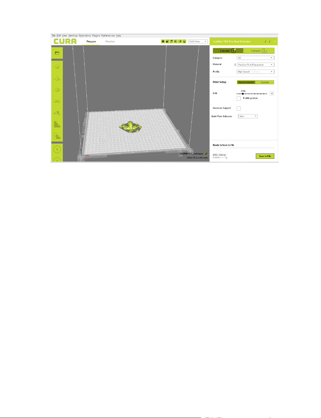
Figure 2.1: Recommended Settings
Material Selection
The lament type categories are separated by ease of use in the top right
corner of the screen. From the Category drop down, select "All" to view
all LulzBot approved and tested materials, or ease of use that you are
comfortable with. The printer ships with a lament sample for the rst
print(s). Refer to the included Quick Start Guide for the proper “First
Run” settings.
Selecting a Quick Print Profile
The prole quality settings can be found in the top right corner of the
window, just below material selection. For most laments, there will be
High Detail, Standard, and High Speed options. Some of the more exotic
laments may only have a single prole.
High Detail
Designed to give greater detail in ner and curved objects. This will
have a smaller layer height, which will make each layer thinner, so
that curves seem more natural and layers seem less noticeable. This
17
Page 18

Cura LulzBot Edition
setting will also increase the total number of layers in the print, which
will increase the overall print time.
Standard
Designed to give a balanced resolution by increasing the layer height
and print speeds. This will make the organic curves slightly more
step-like than the ne setting, but it will reduce printing time.
High Speed
Designed for fast prints where the overall model nish is not the
primary concern. Most commonly used for quick iteration of designs
when rapid prototyping.
Different Filament Manufacturers
Dierent lament manufacturers have dierent formulations for their specic brand. These dierent formulations may have dierent ideal settings.
We highly recommend using the lament brands listed in Cura LulzBot
Edition. Beautiful 3D printed objects start with reliable and consistent
lament. The proles included within Cura LulzBot Edition will be good
starting points for other manufacturers; but they may require changes to
various settings for ideal results.
Infill Selection
Inll represents how solid the inside of your object will be printed. Easily
adjust inll by using the slider to drag the circle to your desired inll. 20%
is a good starting point for most objects.
Printing Support Material
The support option will build up material underneath the portion extending
in mid air, preventing gravity from making it droop. LulzBot 3D Printers
are able to print models that have angles and overhangs, even without
support material. This will depend on the overhang distance and angle
of your particular model le, but a good rule of thumb is greater than 50
degree overhangs will require support. Turn this option on if sections of
your model are extending in mid air. Where support is placed and at what
angle, can be adjusted in advanced settings support.
18
Page 19

2.2. RECOMMENDED PRINT SETTINGS
Build Plate Adhesion
This option is used to select dierent methods for helping ensure your model
stays adhered to the build plate, and the extruder is prepared for printing.
NOTE: In order to reach your full build volume, you will need to select
”none” here. The build plate adhesion techniques use part of your build
volume.
Skirt
The skirt option prints a specied amount of material around the outside
of your object. This prepares the extruder to ensure lament is owing
properly before actually beginning to print your part. It is normal for part
of the skirt to not print, as it is priming the extruder for the actual part.
Brim
Brim creates a single layer attached to and protruding around the base
of your object. This increases the surface area of your print, preventing
warping and ensuring adhesion to the build plate. This single layer thick
line is then manually removed once the print is complete.
Raft
The raft option will build up a layer of material underneath your object as
a ”platform” for the printed object to rest on. This setting can be helpful
when the base of your model is not at.
Load Model File
Select the 3D model you would like to print. Either use the Open Model
button or select File > Open Model. Once the le has been loaded, you
will see a 3D rendering of your object on the build platform. Select the
model to see the various options.
Model Orientation
Move your model to change where it is printed on the build plate. Do
this by left clicking on the model and dragging it to the desired location.
19
Page 20
Cura LulzBot Edition
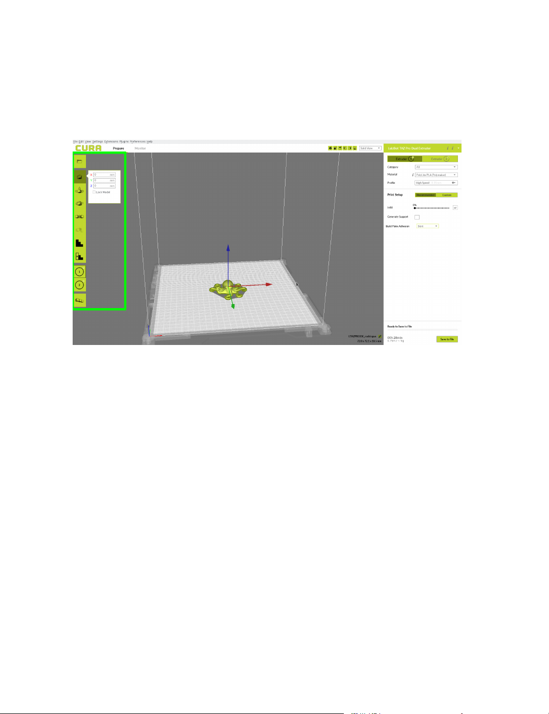
The blue, red, and green outlined corner of the 3D print bed view
represents the front left hand corner of the build plate on your printer. You
can view your model from dierent angles by holding down the right mouse
button and dragging.
Figure 2.2: Options after selecting model
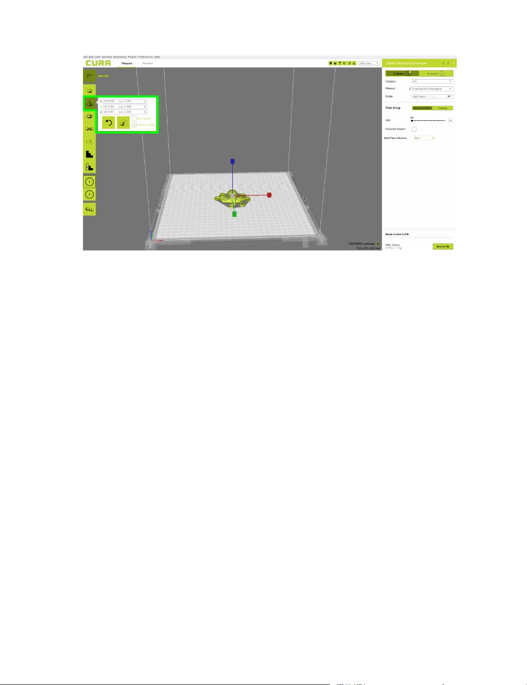
Scale
The Scale button displays the model dimensions, along with the ability
to scale along the X Y or Z axes. Anything below the percentage 100
will reduce the objects size, while anything above the percentage 100 will
increase the objects size. As a default, this is set to uniform scaling when
rst being selected. This will cause the X Y and Z axes to be scaled by
the same amount when you make a change to any of them. To disable this,
unselect the uniform scaling in the lower right hand corner.
20
Page 21
Rotate
2.2. RECOMMENDED PRINT SETTINGS
Figure 2.3: Scaling your Model
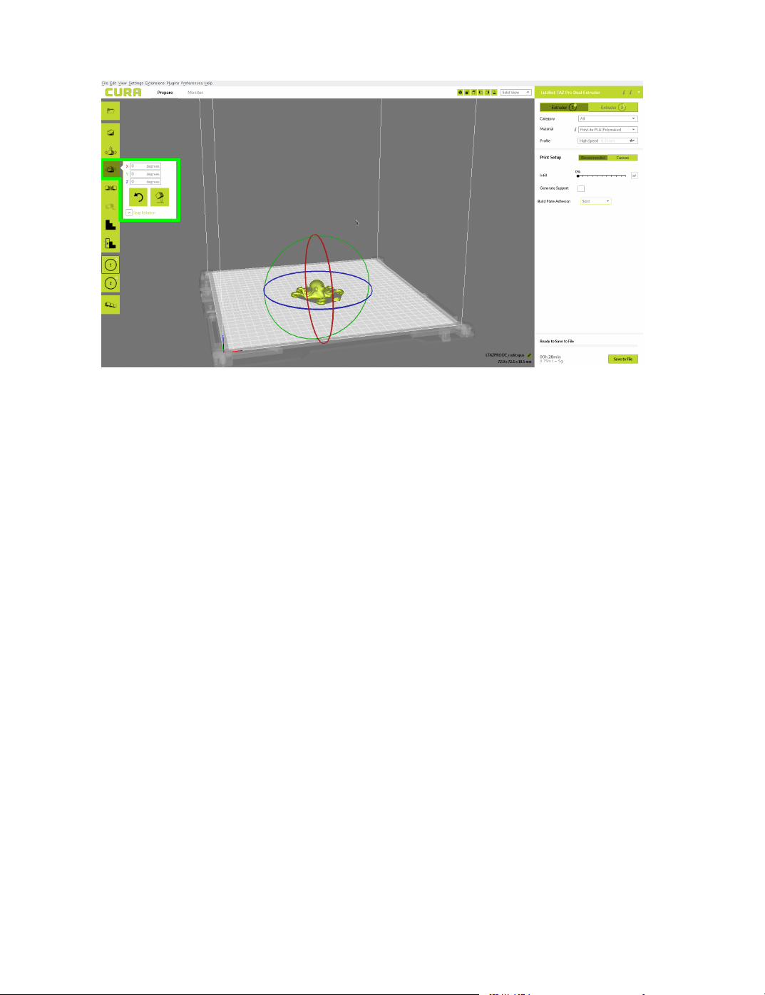
The Rotate button will give you the ability to orient your model along all
three axes. Once you click the rotate button, three circles will surround
your model. The Blue circle will allow you to rotate around the Z-axis.
The Green circle will rotate around the Y-axis. The Red circle will rotate
around the X-axis. Cura defaults to 15 degree increments. Hold Shift to
rotate by One Degree Increments. (Fig. 2.4, page 22)
21
Page 22
Lay Flat
Cura LulzBot Edition
Figure 2.4: Rotating your Model
The Lay Flat option is available after selecting the rotate button. This
will ensure that the at portion of your print is securely attached to the
bed. It is highly recommended to use this option after rotating your model
in the Z direction, as it will help prevent potential adhesion issues during
the print.
Reset
Reset
The
option is available after selecting the rotate button. This
will return your model to the original orientation as dened by the CAD
program when rst loaded.
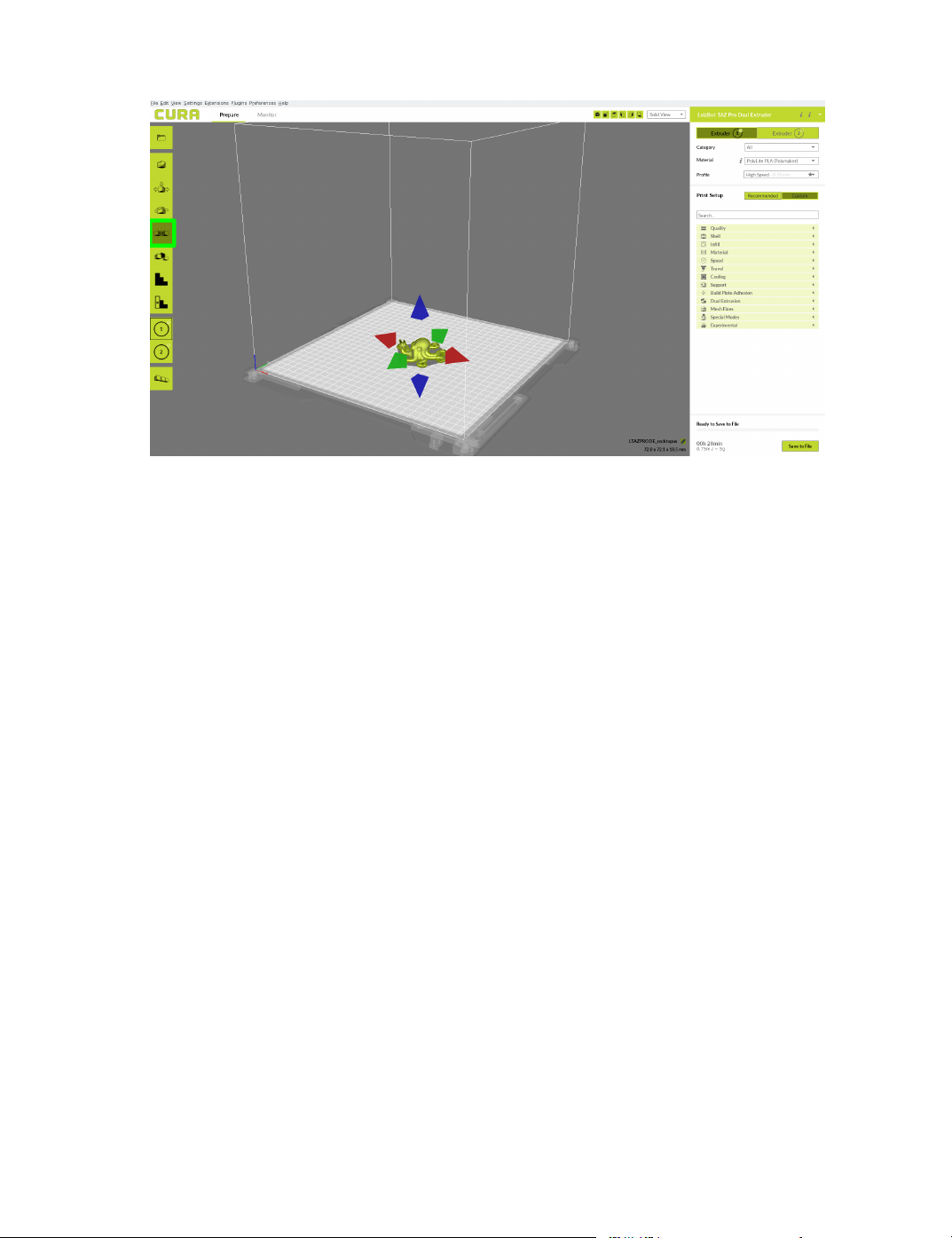
Mirror
The Mirror button creates a reversed / mirrored image of the selected
object in either the X, Y, or Z axis directions.
22
Page 23
2.2. RECOMMENDED PRINT SETTINGS
Figure 2.5: Mirror Button Location
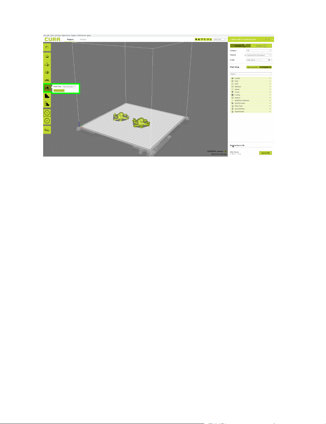
Per Model Settings
The Per Model Settings allows you two print two or more objects with
dierent slicing settings between the two. To activate this, rst select
which model you would like to modify settings on. Once selected, a drop
down option will appear that contains options for “normal mode,” “Print
as support,” “Don't support overlap with other models,” “Modify
settings for overlap with other models,” and “Modify settings
for infill with other models.” After selecting the way you want to
change your settings, click “Select settings.”
23
Page 24
Cura LulzBot Edition
Figure 2.6: Per Model Settings Location
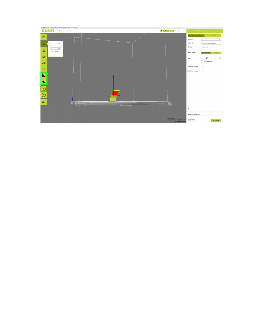
Custom Supports and Support Blocker
Cura 3.6.3 and newer allows the ability to place custom supports where one
wants, and block automatic supports where they are not needed. In order
to use either of these features, you need to disable “Automatically drop
models to the build plate” in “Prefernces > Configure Cura” section.
24
Page 25
2.2. RECOMMENDED PRINT SETTINGS
Figure 2.7: Custom Support Settings Location
After selecting your model and choosing your custom support option,
you can now left click on areas of the model to place blocks. These
blocks will either generate support in just that area, or prevent automatic
support from being generated in that area depending on the choosen
option. This action can also be performed by right clicking the object,
and selecting which extruder you would like to print it. Please note that
when working with the custom supports the blocks that are created won’t
extend all the way down to the build platform. This is normal, as long as
you see the visible block connected to your model then the support was
placed. You can check layer view before printing to ensure proper support
generation/blocking.
Extruder Assignment
Near the lower left hand corner of the prepare screen will be two icons to
easily assign an extruder to a model. Left click your model, and then select
extruder 1 or extruder 2 to print with the respective tool head.
25
Page 26
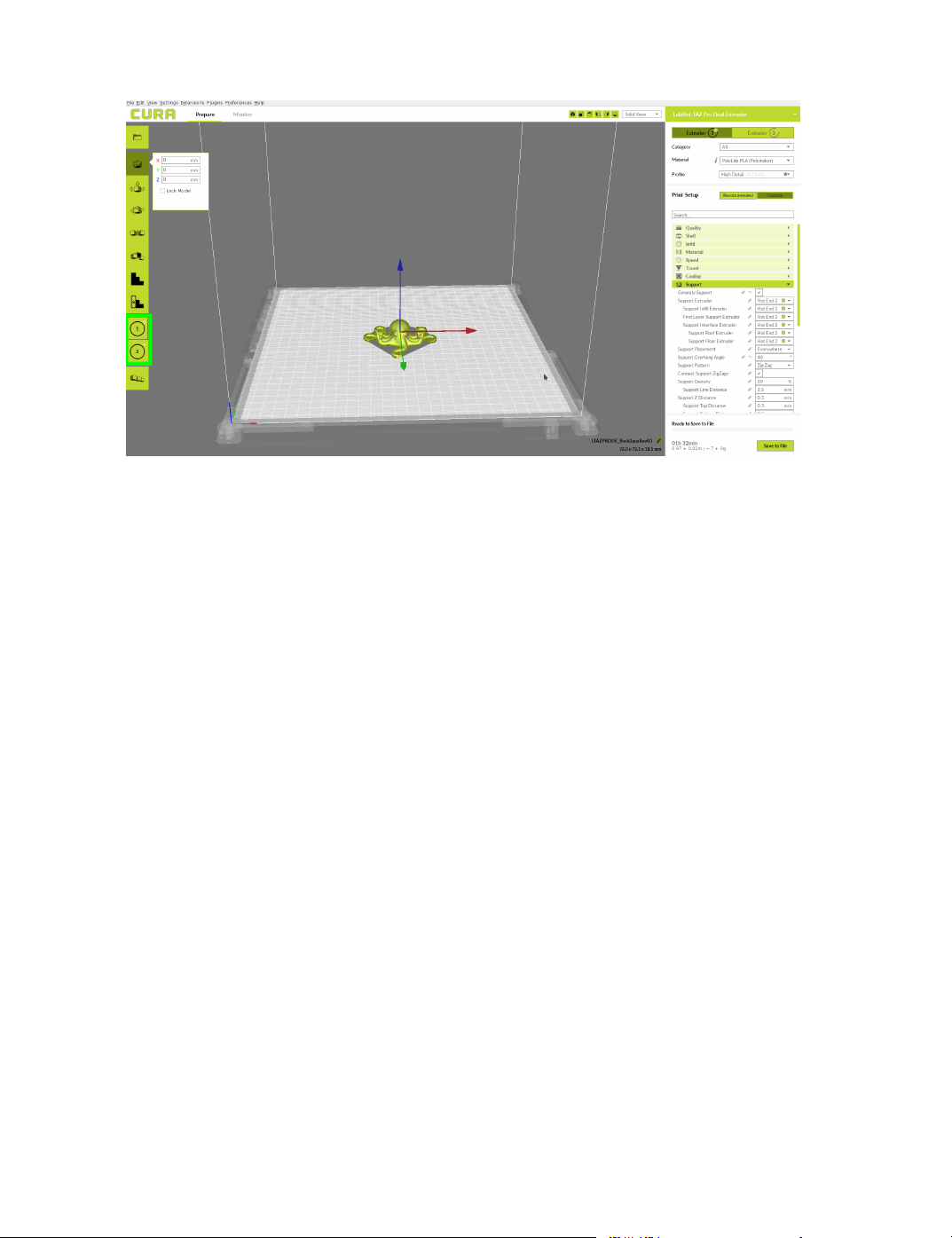
Figure 2.8: Extruder Assignment Location
Multiply Object
Cura LulzBot Edition
In the very lower left hand corner, there will be an easy button to
multiply objects. Select your model, select the multiply object button, and
determine the number of copies you would like. These will be automatically
arranged on the build plate if they t, and can be moved after the automatic
placement. This action can also be performed by right clicking the object,
and selecting multiply object.
2.3 View Options
Dierent modes allow you to view your model in a variety of ways. This
can be helpful for spotting issues before the print even starts. In the top
right hand corner, you can select your dierent view types.
Solid View
This is the standard view and shows the solid outer surfaces of the model.
(Fig. 2.9, page 27):
26
Page 27
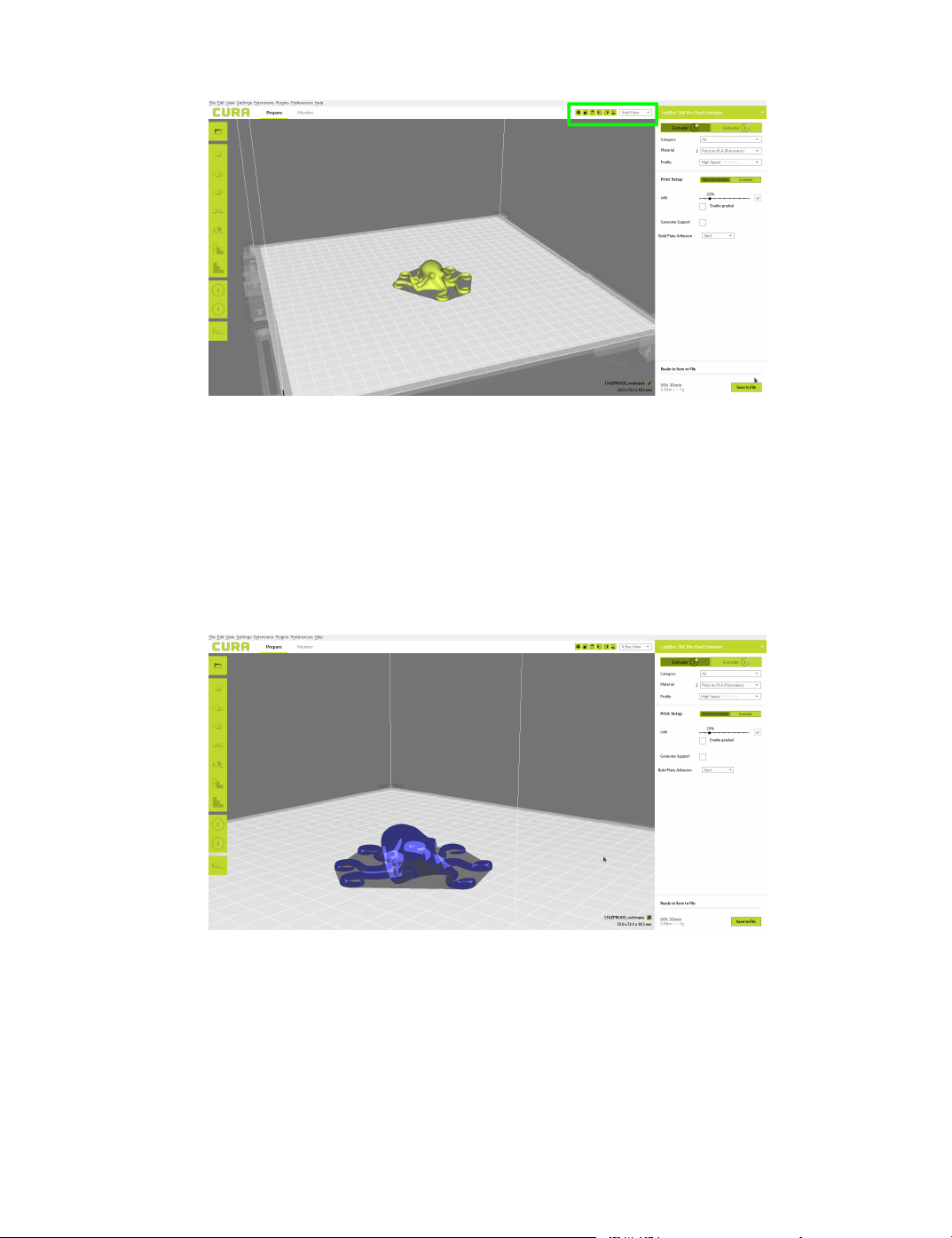
2.3. VIEW OPTIONS
Figure 2.9: View in Normal Mode
X-Ray View
X-ray allows you to look inside of the object. This is helpful for detecting
any manifold errors or other possible issues with your model. Problem
areas will be highlighted in red. (Fig. 2.10, page 27)
Figure 2.10: View in X-ray
27
Page 28
Cura LulzBot Edition
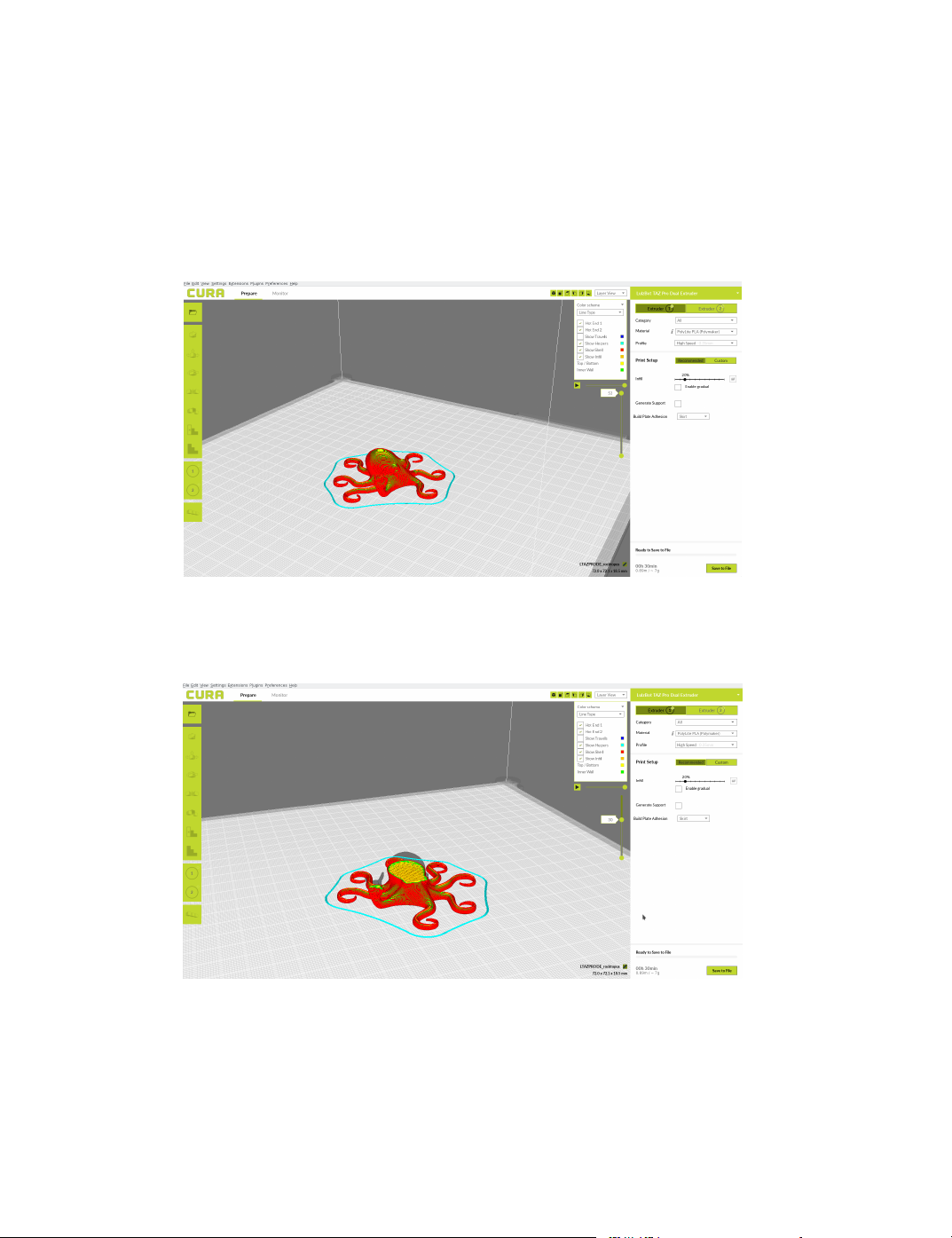
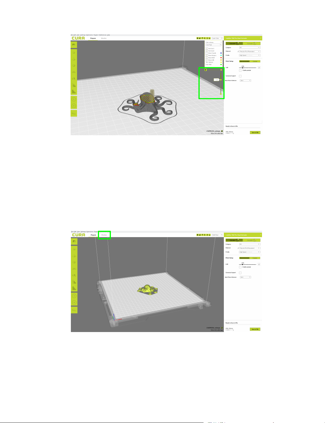
Layer View
To view the tool path of your print head and to ensure no skipped layers
or gaps, use this option. You can select dierent color schemes to highlight
dierent portions of your print. For the rest of these photos and examples,
we will be using “Line Type” color scheme.
Figure 2.11: View in Layers
Figure 2.12: Viewing Cumulative Layers
28
Page 29
2.4. MONITOR SCREEN
Figure 2.13: Viewing a Specic Layer
2.4 Monitor Screen
The monitor screen will allow you to connect to and control your 3D printer.
From this screen you can heat the hot ends and bed, move all axes, send
custom gcode commands, and begin prints. The monitor tab is located at
the top of the prepare screen.
Figure 2.14: Monitor Button Location
29
Page 30
Cura LulzBot Edition
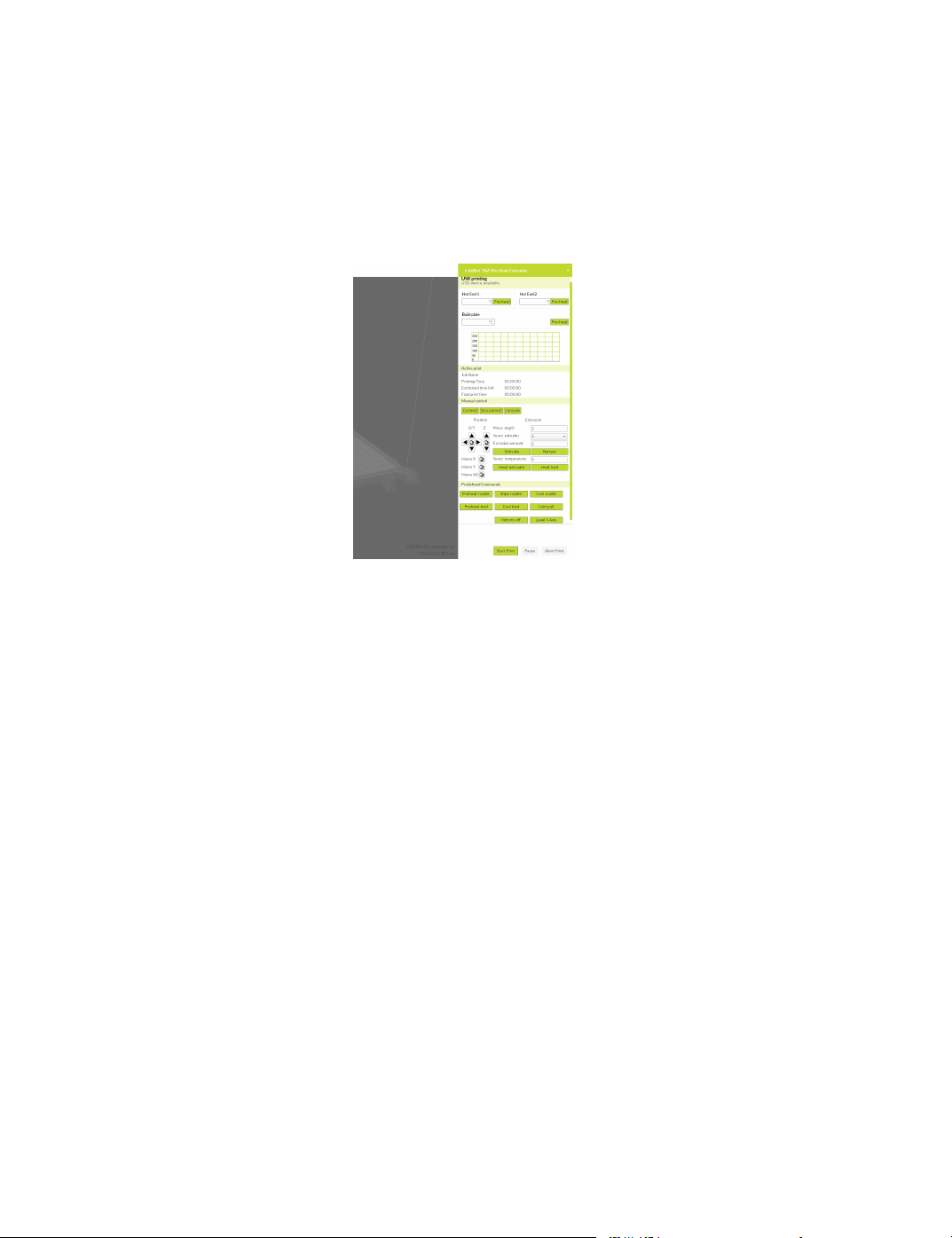
After switching to the monitor tab, the right hand side of the screen
will change and new options will be available to control your 3D printer.
There are 4 main sections that comprise of Temperature Control and Monitoring, Active Print Information, Manual Controls, and nally Predened
Commands.
Figure 2.15: Monitor Control Options
Temperature Control and Monitoring
In the temperature control and monitoring section you can select each hot
end’s temperature and the bed temperature. By selecting the“Preheat”
buttons with no temperature dened in the boxes, it will automatically set
the temperature to whatever is currently set in the quality prole. If you
would like to set a custom temperature, that number can be entered into
the box and select preheat.
The temperature graph below the preheat options will report your
current hot end and bed temperatures.
Active Print
The active print area will report statistics on the status of the current
print job. This reports the File Name, Time Printed, Estimated Time
Remaining, and Final Print Time. Cura LE uses acceleration and jerk
30
Page 31

2.4. MONITOR SCREEN
settings to estimate the print time, be sure to update the stock settings if
you have modied your rmware.
Manual Control
The manual control section will allow you to Connect to your 3D printer,
control movement in all axes, heat all components, and send custom gcode
commands directly to the machine. When your printer is plugged in to your
computer and powered on the connect, disconnect, and console buttons
become available.
Connect, Disconnect, Console
• The connect button will allow you to communicate with and control
your 3D printer. All commands in the Monitor Tab will require you
to be connected before the printer will respond.
• The Disconnect button will terminate the connection with the
current machine.
• The Console button will open a window that monitors communication between Cura LE and your 3D printer. This console can
also be used to send custom gcode commands to your printer. See
http://marlinfw.org/meta/gcode/ for a full list of gcode commands and their functions.
Movement, Heating, Extrusion
After rst connecting to your printer, you will be required to home all axes
before you are allowed to manually move parts of the printer. This is to
ensure the printer knows where its minimum positions are, and prevent
collisions with the frame and/or bed. You will notice multiple input
boxes labeled Move Length, Select Extruder, Extrusion Amount, and Select
Temperature.
• Move Length allows you to specify a distance you would like to move.
After inputting a distance select the positioning arrow corresponding
to axis you would like to move.
31
Page 32

Cura LulzBot Edition
• Select Extruder This option allows you dene which extruder you
will be using when selecting the extrude button.
• Extrusion Amount Input the amount of lament you would like fed
into the print head when selecting the extrude button.
• Select Temperature Set a temperature for the hot end 1, hot end 2,
or the bed. If setting a temperature for a hot end, be sure you have
the correct hot end selected before pushing “heat extruder”.
Predefined Commands
Cura LE comes with predened commands specic to your printer. After
connecting, selecting one of the buttons will perform the following options.
• Preheat nozzle will automatically heat your hot ends to the set
temperature contained within you printing prole.
• Wipe nozzle will initiate the clean nozzle command. This will
home your printer, heat your nozzles to the proles specied wipe
temperature, and clean each nozzle on the wiper pads.
• Cool nozzle will turn o the heat to both hot ends when selected.
• Preheat bed will set your bed temperature to what is dened in your
quality prole.
• Cool bed will turn o the power going to your heated bed, allowing
it to cool to room temperature.
• Cold pull will heat your hot end to the soften temperature set in
your prole, and then remove the lament from your hot end.
• Motors off will turn o the motors for the X axis, Y axis, and
Extruder. Your Z axis motors will remain engaged to prevent the X
axis gantry from falling while powered on.
• Level X-axis will raise your print head to its maximum Z height,
engaging both the left and right hand limit switches at the same time.
If your X-axis is unlevel, you will hear a brief skipping sound as it
levels itself.
32
Page 33

2.5. STARTING YOUR FIRST PRINT
2.5 Starting Your First Print
Once you have your model, prole, and lament loaded, it is time for your
rst print! Refer to the Quick Start Guide included with your 3D printer.
A PDF version is available at LulzBot.com/downloads.
Printing from USB Cable
Connect your 3D printer to a computer using a USB cable, power it on
and select the Monitor button at the top of the main screen. While in the
monitor screen select the connect button. Once connected, you will have
a notication in the top right corner of the screen that states ”Connected
via USB.”
Once you are connected, select "Print" from the lower right hand
corner. This will begin the process of heating your hot ends, cleaning
your nozzles, probing the corners, and starting the print.
USB Printing for Multiple Printers
If you plan to run multiple printers from one computer, you will want
to disable automatic port detection and manually specify which port to
connect to. This can be done through Settings > Printers > Manage
Printers > Machine Settings > Port > (select desired port).
Pausing Mid-Print
You will notice after you click the print button through Cura, the pause
button to the right will become active. When selected, it will pause the
print and automatically move your print head away from your object. This
will allow color changes or material changes mid print.
Automatic Bed Leveling
Before each print your TAZ Pro will go through a wiping and a probing
procedure in order to determine the slope/tilt of your bed. If your nozzle
is dirty or not cleaned properly, this will prevent the printer from being
able to create an electrical contact with the corners. Your TAZ Pro will
automatically retry the wiping and probing procedure if this happens, up
33
Page 34

Cura LulzBot Edition
to a maximum of three times. If three consecutive wipes and probes have
failed, the printer will stop and a warning will sound. When this happens,
clean you nozzles manually while at temperature using the Scotch-Brite
pad included in the tool kit. If this is happening consistently, you should
replace the wiping pad and/or adjust your wiping and probing temps for
that specic lament.
TM
Printing from USB Stick
While in the prepare screen, load your model into Cura with the proper
lament and prole selected. Next, insert the included USB stick into your
computer. In the lower right hand corner of the prepare screen, a drop
down option will appear near “save to le.” Choose “save to removable
drive” and name your .gcode le appropriately. Once saved, select “eject”
from the pop up window.
Start Print
Thanks to the TAZ Pro’s automatic bed leveling system, it is now time to
kick o the print! Insert the USB Stick into the printer. Through the LCD
screen go to: USB Drive > Select Desired .gcode File > Print. Your
TAZ will then go through the process of heating, cleaning, and probing your
bed before starting the print.
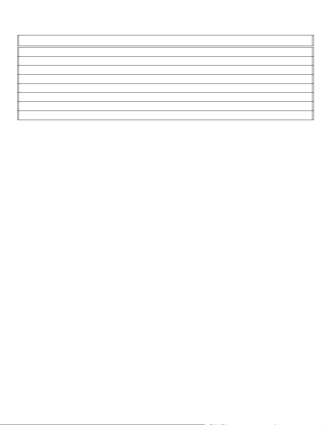
Recommended Temperatures and Bed Preparation
When generating GCODE, it may be benecial to adjust temperatures
depending on your specic model le or lament. We have also found that
for certain materials applying unscented glue stick to the print surface is
required for successful bed adhesion and/or part release. Glue stick can also
be added to help rst layer adhesion on any material, and may be helpful
for objects with a larger surface area. You can nd our recommended
temperature ranges and adhesion techniques below.
34
Page 35
2.6. REMOVING YOUR FIRST PRINT
Filament Type Bed Preparation Nozzle Temp Bed Temp Removal Temp
ABS Clean PEI 245-270 110 50
Nylons Gluestick 240-270 65 45
TPU’s Gluestick+PEI/Clean Glass 225-240 60 25
Polycarbonate Gluestick 250-295 60-110 45
PETG Gluestick 235-265 80 45
PLA Clean PEI 215-235 60 45
Soluble Support Clean PEI 200-230 60 45
PolyCast Clean PEI 215-235 60 45
Table 2.1: Recommended Temperatures (C)
2.6 Removing Your First Print
After your rst print has nished, wait for the print surface to cool to
the recommended print removal temperature. Your parts will be easier
to remove if you allow your heated bed to cool down to optimal temperature. Your print bed will move forward once the model is ready
to be removed.
Once your heated bed has cooled, use the blue handled knife that was
included with your toolkit to remove the item. Carefully insert the blade
of the knife between your print and heated bed. Once underneath the part
rotate the blade lifting with the sharp edge into the part, to gently pop the
piece o your plate.
2.7 Custom Settings
Custom Settings should not be used until enough experience with 3D
printing has been gained to feel comfortable with all aspects of the printer
and its operation. Recommended Mode will provide good results for most
models. The rst time Cura is launched it will default to the Recommended
Settings interface. In order to have more control of your slicing and
GCODE generation, you can switch to Custom Settings.
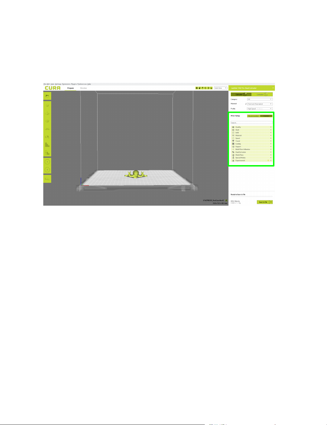
First choose your desired Quick Print prole, this will then copy over
the current settings when changing to Custom Settings mode. Select
35
Page 36
Cura LulzBot Edition
the Custom button next to the recommended button. The following drop
down tabs will now be available: Quality, Shell, Inll, Material, Speed,
Travel, Cooling, Support, Build Plate Adhesion, Dual Extrusion, Mesh
Fixes, Special Modes, and Experimental.
Figure 2.16: View in Custom Settings
Setting Visibility
When rst switching to custom settings, some options will be hidden by
default. To select which options are available, go to Settings > Congure
Setting Visibility You can now select which settings you would like available
and which ones you would like hidden. This can be helpful for new users, or
when teaching others the basics of 3D printing. In order to view all settings,
select the checkbox in the top left near “check all.” For the remainder of
this manual, we will assume every option is visible.
2.8 Quality Tab Settings
This section will allow you to modify and adjust multiple settings that are
dependent upon nozzle shape and diameter for specic parts of your print.
36
Page 37
2.8. QUALITY TAB SETTINGS
Layer Height
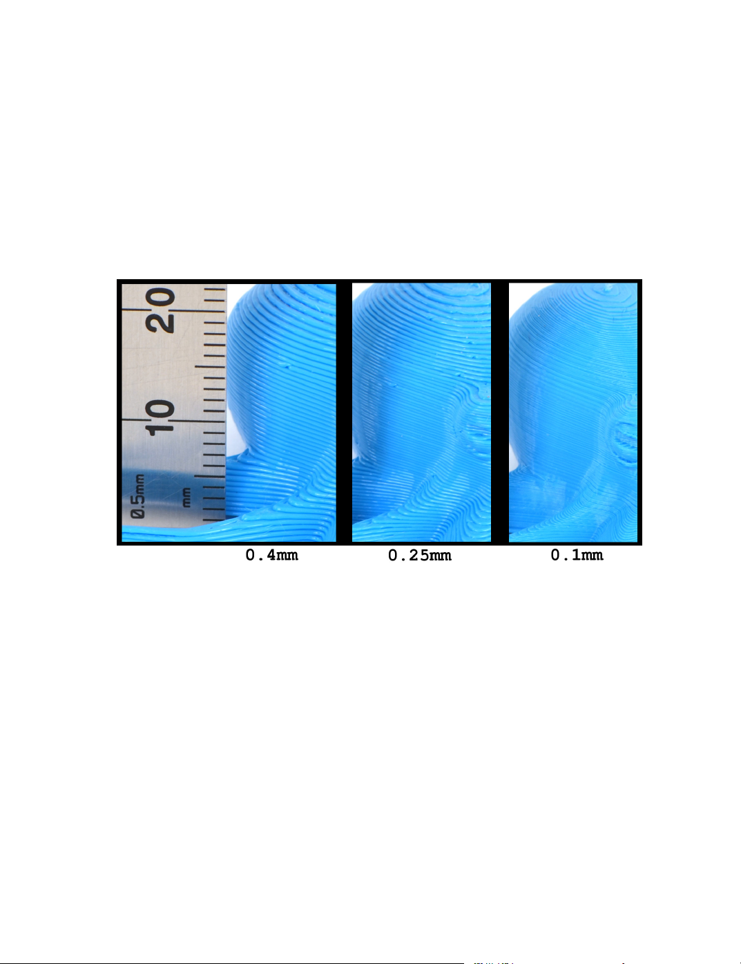
The thickness of each printed layer is known as the “Layer Height”. The
smaller the layer height, the smoother curves will appear. Smaller layer
heights will also increase print time, as it will take more layers to complete
the object.
When you have dierent layer heights between extruder 1 and extruder
2, the dierence will be averaged. This is required as when printing each
nozzle needs to print at the same height to avoid collisions with your object.
Figure 2.17: Dierences in Layer Height
Initial Layer Height
The initial layer height will be the thickness of your rst layer being printed.
A larger layer height will help ensure adhesion of your part, and help prevent
it from coming loose mid print. We have the default value set to 0.4 mm
for every quality prole, to prevent adjustments to Z oset when swapping
between quality proles. After the rst layer is complete, the thickness will
return to the “layer height” set within the prole.
37
Page 38

Cura LulzBot Edition
Line Width
The line width will represent how wide the extruded plastic will be. This
setting is set to your nozzle diameter by default. It is impossible to extrude
a line that is skinnier than your nozzle diameter, and as such the default
value is set to your nozzle diameter (0.5 mm.) You can increase line
width up to 1.25 mm with the stock nozzle, as this represents the width
of the ”at” portion of your nozzle tip. With other nozzles installed, these
numbers will vary.
There are several dierent areas in which you can apply line width
adjustments exclusively.
• Wall Line Width will alter the width of the extrusion on “walls”
only. These will be the outermost vertical shells that comprise of
your model.
• Outer Wall Line Width will change just the outer most walls line
width. These can be visualized as the red areas of your model in
“Layer View.”
• Inner Wall Line Width will change just the inner most walls line
width. These can be visualized as the green areas of your model in
“Layer View.”
• Top/Bottom Line Width will change the top and bottom layers line
width. This can be helpful for ne tuning surface quality on the nal
object.
• Infill Line Width will change how wide your internal structure
lines are extruded for the top and bottom thickness setting. Increasing this can be helpful for strength, but will use more material.
• Skirt/Brim Line Width will change how wide your skirt and/or
brim are printed depending upon your selection.
• Initial Layer Line Width will determine how wide your initial
layer is placed onto the plate.
38
Page 39

2.9. SHELL TAB SETTINGS
Backlash Fading Distance
Backlash is the amount of play in a mechanical system when changing
directions. During the probing sequence before each print, your printer
will measure the number of motor steps it takes to break electrical contact
when raising the tool head. These steps are then used to determine backlash
in the Z direction. This measurement is used to add additional steps
when making movements in the Z direction to compensate for your specic
machines backlash. After time and movements in the Z direction, this
backlash will no longer be present and can be faded out.
The fading distance will determine over how many millimeters in Z to
“fade” the backlash compensation. For example, if you are printing in 0.25
mm layer heights, and set fading distance to 1 mm you will use:
• 100% backlash correction on the rst layer
• 75% backlash correction on the second layer
• 50% backlash correction on the third layer
• 25% backlash correction on the fourth layer
• 0% backlash correction on the fth and subsequent layers.
Backlash correction is turned on at 100% for the entire print by default by
setting the layers to “99999.” This is very helpful when printing at extremely
small layer heights (less than 0.1 mm.) If you would like to use turn o
backlash compensation, set this value to 0.
2.9 Shell Tab Settings
This section will allow you to change all of the settings used to generate
the outer portions of your model. This includes inner walls, outer walls,
top surface and bottom surface settings.
Wall Extruder
The wall extruder option will allow you to specify which nozzle will be used
for the inner and outer walls. This option is only available while using the
Dual Extruder, and can be used to force specic material combinations for
the outer shell of your object.
39
Page 40

Cura LulzBot Edition
Wall Thickness
The wall thickness setting is used to dene how thick your outer shell is.
When setting a wall thickness in millimeters, it should always be a multiple
of your nozzle diameter or wall line width if you have made adjustments to
that setting. If this is not an even multiple, Cura will attempt to match
the distance as close as possible and may lead to undesired results.
The wall line count will dene the number of walls to be printed.
This will pull information from your nozzle diameter and wall line width,
to automatically override the wall thickness number.
Outer Wall Wipe Distance
The outer wall wipe distance will insert a short travel path into the inner
wall before making a travel move. This is intended to allow any ooze from
the nozzle to be caught and distributed on the interior of a print, giving a
cleaner surface. Half the nozzle diameter is a good recommended starting
point.
Top Surface Skin Layers
The top surface skin layers allows you to make custom adjustments to
just your top layer. When activated you can adjust your top pattern, the
number of top layers, the inll pattern, and the inll direction. By changing
these variables you can get dierent results for the top of your model to
meet mechanical and aesthetic requirements.
Top/Bottom Extruder, Thickness, Pattern
The top/bottom extruder option allows you to specify an extruder for
printing the top and bottom layers. This can be helpful depending on
the needs of the print, but usually will not require adjustment. In this
section, you can also individually specify the top and bottom thickness,
pattern, and direction of your model. You have the option to set a
thickness in mm, or dene it by the number of layers. As with the top
surface patterns, you can adjust the inll pattern and angle for these layers
here.
40
Page 41

2.9. SHELL TAB SETTINGS
Outer Wall Inset
The outer wall inset will allow you to print your outer wall skinnier than
the nozzle of your diameter. This is accomplished by slightly overlapping
the inner wall by the amount dened here.
Optimize Wall Printing Order
This setting will attempt to optimize your tool path, speeding up the overall
duration of the print. This will create a dierent order of operations on how
your model is created, to reduce time. This can lead to quality concerns
with alternating outer walls, and should only be used when that is not of
concern.
Outer Before Inner Walls
Printing the outer walls rst can improve X/Y dimensional accuracy. As
you will be printing the outer walls rst, this setting can lead to cosmetic
defects on the outside of your model from extra or missed extrusion after
a travel move.
Alternate Extra Wall
The alternate extra wall option will add an extra inner wall every other
layer. This gives the inll very secure adhesion with the inner and outer
walls, greatly improving strength. This setting will add additional print
time to your model.
Compensate Inner/Outer Wall Overlaps
While generating a tool path for inner and outer walls, sometimes an overlap
will occur depending on model geometry. By activating inner and/or outer
compensate overlaps it will slightly reduce extrusion in this area, preventing
too much material from building up.
Minimum Wall Flow
After activating compensation for inner and/our outer wall overlap, a
minimum wall ow percentage setting will appear. This sets a minimum
41
Page 42

Cura LulzBot Edition
ow percentage when compensating to never go below, helping ensure the
strength of your nal object.
Fill Gaps Between Walls
This option will attempt to ll small gaps that are generated depending
upon model geometry. For example, if you have a 2.2 mm cube, with wall
thickness set to 1 mm you will have a 0.2 mm gap in the center of the cube.
With this setting activated, it will ll the 0.2 mm gap providing stronger
parts. With this setting disabled, it will leave the space empty which may
produce more accurate parts.
Filter Out Tiny Gaps
Filter out tiny gaps will try to identify any mesh errors, or tiny gaps in the
outer section of your model. This reduces starts and stops, and helps the
outer surface nish of your print.
Print Thin Walls
The print thin walls option will attempt to print sections of your print
that are smaller than your nozzle diameter in the X/Y plane. It is not
recommended to use this setting on objects that are less than 1/2 your
nozzle diameter.
Horizontal Expansion
The horizontal expansion setting will add a set oset to your model object.
Positive values can compensate for too large of holes, while negative values
can compensate for too small of holes. You can set this for the entire print,
or specically for the initial layer.
Z Seam Alignment
As your printer builds up layer by layer, there is a start and stop point
to each layer before moving up in Z. Where this location happens on your
outer most shell is referred to Z seam alignment. You have four separate
options to choose from while dening this location:
42
Page 43

2.9. SHELL TAB SETTINGS
• The Shortest option will set the Z seam location to the shortest path
possible. This can speed up print time while leading to a systematic
Z seam depending upon model geometry.
• The Random option will generate a random start and stop location
for each layer, causing the “seam” to be broken up between layers.
• The Sharpest Corner option will place the Z seam along a corner,
allowing it to be less noticeable.
• The User Specified selection will allow you to specify a X/Y
coordinate on the bed plate. The Z seam will be placed as close
to this location as possible when making Z-axis moves.
Seam Corner Preference
Cura will automatically try to set up the Z seam on a corner, unless user
specied is selected in alignment. The seam corner preference setting allows
a user to dene how a seam is hidden, without needing to manually dene
a coordinate. You have four options with this setting:
• The None option will ignore the corners of your objects while setting
up Z seams.
• The Hide Seam option will attempt to put your Z seam on an inner
corner, making it harder to see.
• The Expose Seam option will attempt to put your Z seam on an outer
most corner, making it more visible.
• The Hide or Expose Seam option will allow Cura to decide to place
the seam on an inner or outer corner. Cura will choose whichever
option is quickest to complete the print.
Ignore Small Z Gaps
Ignore small z gaps prevents excessive processing time while generating
gcode and printing. If there is a small gap in the Z direction of your model,
a top and bottom skin can be generated in the gcode. Checking this option
will prevent the additional skin from being generated.
43
Page 44

Cura LulzBot Edition
Extra Skin Wall Count
Extra skin wall count will add additional walls for your top and bottom
layers only. This is used as a cosmetic eect, and can also be used to help
top layers when using sparse inll.
Ironing
Ironing is a process where your nozzle will go over a horizontal top layer,
performing a smoothing action giving cleaner top surfaces. After activated,
several new options will appear.
• Iron only highest layer will prevent ironing from occurring on
every horizontal layer, and only iron the topmost horizontal layer.
• Ironing pattern will allow you to specify how your horizontal layers
are ironed. It is recommended to check layer view after selecting to
ensure the ironing pattern ts your needs.
• Iron line spacing determines how far apart the lines are when
“ironing” your top layers.
• Ironing flow allows you to extrude slightly while ironing. This can
help ll any gaps in the top layer, but can be detrimental if set too
high.
• Ironing inset will allow you to determine a distance to avoid from
the outer edge of your object. This prevents material from being
pushed over the wall of your object.
• Ironing speed allows you to specify a speed at which the ironing
will occur.
2.10 Infill Tab Settings
The inll section in custom settings controls how the inner portions of your
model are printed. Here you will nd details on how each setting will aect
your overall print.
44
Page 45

2.10. INFILL TAB SETTINGS
Infill Extruder
On a dual extruder printer, you can specify which hot end will be used for
inll of the object. If you select “not overridden” it will print the inll for
each object with the assigned extruder
Infill Density
You can dene an inll percentage, and Cura will automatically place inll
at the proper spacing to meet this percentage. Cura will follow whatever
pattern you have selected on inll pattern. Alternatively, you can specify
a line distance and it will ignore the inll percentage setting.
Infill Pattern
The inll pattern will determine the path of how your inll is generated.
There are several dierent patterns to choose from, oering dierent
benets and drawbacks.
• Grid will create inll by making a continuous line, bouncing o each
wall at 45 degree angles. This is one of the faster inll types, as there
are no wasted moves on travel are implemented.
• Lines will create the same patter as grid, however it generates them
dierently. It will generate all inll lines at 45 degree angles to your
wall in one direction, and will then generate all perpendicular lines
the other direction. This constrains travel moves along the inner wall.
• Triangles will create a triangular pattern of inll. Similar to grid,
it will “bounce” of interior walls to a new angle, preventing any
superuous travel moves.
• Tri-Hexagon generates a hexagon inll pattern, with a triangle
attached to the edge of each hexagon.
• Cubic generates 3-dimensional hexagons, with pyramids lling in the
gaps. This helps increase strength, without adding much to overall
print time.
45
Page 46

Cura LulzBot Edition
• Cubic Subdivision generates an inll pattern similar to Cubic,
however it leaves the center of your model at a lower density. This
pattern helps support walls, while decreasing print time by printing
less material.
• Octet generates a 3D cube pattern with the cubes standing on a
corner relative to the build plate. This pattern helps increase strength
by generating an internal 3 dimensional object, while keeping print
time down by only printing in straight lines.
• Quarter Cubic generates a similar pattern to octet, however it
generates rectangles on its corner opposed to cubes.
• Concentric builds internal walls, that are not connected to your
outer walls. This inll will help save material, but may leave the
outer walls of your nal object weaker.
• Zig Zag will create an grid inll pattern similar to lines. However
instead of traveling along the interior wall, it will extrude during this
move increasing strength on your nal object.
• Cross will generate a vertical “X” pattern within your inll. This
pattern has a lot of stops and turns, and will increase your print time
of your nal object.
• Cross 3D will generate a 3 dimensional “X” pattern within your
object. As with cross ll, the starts and stops will increase total
print time of your object. The 3 dimensional crosses will also provide
more strength than the standard cross pattern.
• Gyroid generates a wave pattern that rotates rotates along your inner
walls as your object builds up. This generates 3 dimensional shapes
for increased strength, while being very pleasing aesthetically.
Connect Infill Lines
This setting will add extra extrusions along the interior walls of your object.
This helps increase strength of your object, and helps prevent inll lines
from being seen through the outer shell of your objects.
46
Page 47

2.10. INFILL TAB SETTINGS
Infill Line Directions
This setting will allow you to dene the direction of inll lines globally. You
will be required to leave the brackets surrounding your input for proper
functionality. It is recommended to check layer view after updating this to
ensure desired results.
Infill Offset Directions
This setting will allow you to change how your oset is placed in either the
X or Y directions. This can be helpful if you have a small part, and would
like to ensure inll is centered in that section.
Infill Line Multiplier
This option will multiple how many inll lines are generated internally. By
default your inll will generate one line, multiplying this by 2 will make it
2 lines, side by side, in the same pattern. This can increase part strength
at the cost of additional material and print time.
Infill and Skin Overlap Percentage
Inll and skin overlap percentage dene the amount of overlap with inll
based upon nozzle diameter. Inll overlap will dene the amount of inll
that is extruded into your inner wall, while skin overlap will determine
how much inll is extruded into the outer wall. Setting these too high will
show inll patterns through your outer wall. You can dene each section
by nozzle percentage overlap, or by a specic distance.
Infill Wipe Distance
This setting will determine how far into your inll your nozzle will move
and the end of an inll layer. This will deposit any material on the interior
of the model, and prevent drippage on the outside of your model.
47
Page 48

Cura LulzBot Edition
Infill Layer Thickness
You can specify how thick your inll layer lines are here. It is important to
always keep this a multiple of your layer thickness. If this is not a multiple
of layer height, your nozzle can drag through already printed parts.
Gradual Infill Steps and Step Height
These settings modify how inll is generated from base of your object
towards the top of your object. The inll steps will determine how many
times your inll density is halved when moving down from the top of your
object. The step height will determine how “thick” each section is before
being halved.
Infill Before Walls
This option will force your printer to build the inll section of the layer
before printing the inner and outer walls. This is helpful for increasing
adhesion and strength to the outer shells, but can lead to cosmetic defects
on the outer shell.
Infill Support
Inll support will help save material by only printing inll where the tops
of objects require it. While saving time and material, the nal object will
be weaker and not uniformly strong.
Skin Removal Width
Skin removal width will limit how wide your inner and outer walls are on
angled objects and top/bottom layers. This can help reduce material costs,
but can lead to weaker objects and cosmetic defects depending on model
geometry. This can be set for all portions of the model, or just top and/or
bottom layers.
48
Page 49

2.11. MATERIAL SETTINGS TAB
Skin Expand Distance
The skin expand distance setting will force your inner and outer walls into
the inll, increasing adhesion and strength. You can specify this for the
entire object, or just for the top and/or bottom layers.
Maximum Skin Angle for Expansion
Dening the angle and width for skin expansion can rene where and when
the extra material is being laid down. A 90 degree will refer to a vertical
setting, while 0 degrees will represent a horizontal surface. You can also
dene where this happens based upon minimum wall thickness.
2.11 Material Settings Tab
The material settings tab will allow you to control how your 3D printers
hot end(s) and extruder(s) deposit lament. This includes all temperatures,
retractions, and ow rate for dierent portions of your print.
Default Printing Temperature
The default printing temperature is dened by the material, and serves a
good base point for new proles.
Printing Temperature
The printing temperature will override default printing temperature setting.
Reduce this setting if you are seeing a lot of stringing on nal prints, and
increase this setting if you are getting weak layer adhesion.
Probe Temperature
The probe temperature determines at what temperature your printer will
probe the 4 corners before each print. The goal of this setting is to be hot
enough to account for metal expansion when probing, but cool enough to
prevent material from dripping out. If you are seeing multiple consistent
probe failures with a specic lament, this will be a setting to adjust.
49
Page 50

Cura LulzBot Edition
Soften Temperature
Before each print, your printer will remove the lament from the hot end
before wiping and probing the nozzle. This setting determines at what
temperature the lament is removed from your hot end before that process.
The goal is to have the lament hot enough to remove from the hot end, but
cool enough to prevent dripping during the cleaning and probing process.
Wipe Temperature
The wipe temperature will determine what temperature your hot end cleans
itself on the wiping pad before each print. The goal is to be hot enough to
clean the nozzle, without damaging the wiper pad. We recommend keeping
this setting at 200 Celsius or lower to help the life of the wiper pad.
Printing Temperature Initial Layer
In order to help part adhesion, it can sometimes be helpful to print the rst
layer of your object at a higher temperature than the rest of your object.
You can specify this temperature here. A good rule of thumb will be to
keep the initial layer 5 Celsius hotter than the rest of the print.
Initial Printing Temperature
During dual extrusion, your inactive nozzle will cool down to standby
temperature. As the printer comes closer to switching nozzles, it will begin
to heat from standby temperature to initial printing temperature before
moving to printing temperature. It is recommended to keep initial printing
temperature 5 Celsius lower than printing temperature.
Final Printing Temperature
As your print progresses during dual extrusion, there will be a time when
your printer swaps to its other nozzle automatically. Before switching to
the new nozzle, your active nozzle will begin to cool to your nal printing
temperature. As with initial printing temperature, it is recommended to
keep this temperature 5 Celsius below normal printing temperature.
50
Page 51

2.11. MATERIAL SETTINGS TAB
Extrusion Cool Down Speed Modifier
The extrusion cool down speed modier can be used to adjust heat to your
hot end when extruding large amounts of plastic. This will send more power
to the heater cartridge, prevent temperature dips and extrusion issues when
printing at high speeds and/or high layer heights.
Build Plate Temperature
The build plate temperature will be used to help keep your object adhered
to the bed during the printing process. In general, keeping this set at glass
transition temperature for your specic lament is recommended.
Part Removal Temperature
The part removal temperature will dene at what point your bed moves
forward, indicating that your printed part is ready to be removed from
the build plate. In general, you DO NOT let the build plate cool fully to
room temperature. This can cause bubbling in your PEI sheet as the part
contracts, increasing the rate at which you need to replace that consumable.
Keep Heating
This option will prevent your heated bed from cooling down after a print,
and will maintain your part removal temperature. We highly recommend
keeping this setting activated, as it will extend the life of your PEI print
surface.
Build Plate Temperature Initial Layer
More often than not, it is benecial to have an initial bed temperature
hotter than the rest of the print to help adhesion. Set the bed temperature
to the desired temperature for the duration of the print, and adjust the
initial layer accordingly here.
Diameter
The diameter setting is used by Cura to calculate exactly how much
lament is being distributed during the printing process. In order to get
51
Page 52

Cura LulzBot Edition
the most accurate prints, you can update this setting by measuring your
lament diameter in multiple places and inserting the average here. We
recommend starting with the laments included within Cura LE, as these
measurements have already been taken.
Flow Rate
The ow rate can be set in order to account for die swell. A number above
100% will have your printer extrude more lament, while a number below
100% will reduce the amount of lament being extruded. Increasing the
initial layer flow rate can help rst layer adhesion, and prevent your
object from popping o mid print without aecting quality results of the
rest of the object.
Retraction
Retraction settings control how the lament is pulled out of your hot end
when it is not extruding. Getting these settings just right will prevent
leaked lament from falling on your part during travel moves and dual
extrusion.
Enable Retraction
Enabling retraction causes the lament to be backed out of the hot end
when not in use. This prevents lament from leaking on your part during
travel moves, and when the hot end is not in use. Some more exible
laments can be more reliable with this turned o, as it will prevent
jamming and kinking of the lament within the hot end.
Retract at Layer Change
Retract at layer change will have your extruder remove lament from the
hot end when moving up in layers, and positioning to the beginning of the
next layer.
52
Page 53

2.11. MATERIAL SETTINGS TAB
Retraction Distance
The retraction distance will determine how much lament is removed from
the hot end during regular retraction moves. A good general starting point
is between 1 mm and 3 mm.
Retraction Speeds
The retraction speed setting will determine at what speed you retract
lament from your nozzle, and what speed that lament is re-inserted
into the nozzle during normal retraction moves. In general, a speed
from 10 mm/s to 25 mm/s is good for most laments. You can specify
separate retract and prime speeds using retraction retract speed and
retraction prime speed.
Retraction Extra Prime Amount
Retraction extra prime amount will add extra material when priming the
nozzle after a retraction. This can be helpful for materials that are springy,
and can compress when attempting to re-prime. In general, this setting
should be left at 0.
Maximum Retraction Count
The maximum retraction count limits how many retractions can be performed during the minimum extrusion window. These settings prevent
multiple retraction moves over the same piece of lament, reducing the
likelihood of a strip out while extruding.
Standby Temperature
During dual extrusion, your inactive hot end will be set to a lower standby
temperature to prevent oozing and dripping. This temperature should be
close to your soften temperature, but can be adjusted as needed to prevent
oozing.
53
Page 54

Cura LulzBot Edition
Nozzle Switch Retraction Distance and Speeds
The nozzle switch retraction distance and speeds will be applied when
switching between nozzles during dual extrusion printing. The nozzle
switch retraction speed, prime speed, and retraction distance can be
tweaked independently from standard settings. Adjusting these will help
prevent dripping and color bleed with multiple materials and colors.
2.12 Speed Settings Tab
The print speed settings tab will allow you to control how quickly dierent
portions of your print are produced. Just like a motor vehicle, your car
may be able to drive 120 mph but it will handle better at 30 mph. The
general rule of thumb is print slower for better results.
Print Speed
The print speed setting will be generic default. If there is no speed specied
for a specic section in your prole, it will default to whatever is set here.
Infill Speed
The inll speed setting will determine how quickly your inll is laid down.
In general this setting can be faster than the wall speeds, as any printing
defects here will be covered by your outer shell. Moving too quickly here
can prevent inll from adhering properly, causing weaker parts.
Wall Speeds
The wall speed sections will dene how quickly the vertical walls of your
model will be laid down. Having a slower outer wall will improve cosmetic
results. Having your inner wall set to a speed between outer wall and inll
will allow for better inll to wall adhesion, thus stronger parts.
Top/Bottom Speed
The top and bottom speed setting will control how quickly your top and
bottom layers are laid down. Having a slow top and bottom layer helps
adhere your object to the bed, while giving more detailed top surfaces.
54
Page 55

2.12. SPEED SETTINGS TAB
Initial Layer Speeds
You can set your initial layer speed separately to help ensure a good bond
with the plate on the rst layer. A slower initial layer travel speed will help
ensure your nozzle does not run into the print, releasing it from the bed.
Skirt/Brim Speed
Here you can dene how quickly your skirt and brim are being placed down.
As this setting primarily aects the rst layer, it is recommended to keep
this the same as your rst layer speed to help ensure adhesion.
Maximum Z Speed
This setting can limit how quickly you are allowing your printer to move in
the Z direction. If you attempt to move faster than your rmware allows,
your rmware will override this setting and prevent movement. Leaving
this setting to 0 will rely on Firmware Maximums to prevent too quick of
movement.
Number of Slower Layers
This setting will slow down additional layers past the initial layer speed
settings. The speeds will slowly increase over X number of layers, moving
from initial layer speeds to standard speeds.
Equalize Filament Flow
This setting will automatically speed up or slow down your print, to
maintain an equal ow volume. After initiating this option, you will be
able to dene the maximum speed at which your printer will move. If you
choose to use this ability, it is best to nd your maximum extrusion speed
for your specic lament and temperature.
Enable Acceleration and Jerk Control
Enabling Jerk and Acceleration control will allow you to specify dierent
accelerations and jerks depending upon specic parts of your print. Initially
all settings are set to your rmware defaults, and can be adjusted higher
for faster prints or lower for slower more accurate prints.
55
Page 56

Cura LulzBot Edition
2.13 Travel Tab Settings
The travel tab setting will dene how your printer moves when not
extruding material onto your part
Combing Mode
Combing mode will control where your hot end moves when not extruding
material. There are four options that will slightly dier in how the printer
handles this process:
• Off will allow your hot end to take the shortest possible route when
developing a tool path.
• All will prevent your hot end from moving over previously printed
areas while traveling. This can help reduce visible oozing, allowing a
cleaner outer surface of your object. This will increase print time, as
the travel path will need extra moves to avoid those sections of your
print.
• No Skin will prevent the hot end from moving over nal surface areas,
providing cleaner top surfaces.
• Within Infill will keep the travel paths of the tool head within
inll areas whenever possible. This will allow for cleaner walls and
top surfaces, at the expense of additional print time.
Avoid Printed Parts When Traveling
Avoid printed parts when traveling will add additional travel moves to
prevent your nozzle from going over a previously printed part. This can
be helpful when printing multiple objects on the same plate to prevent any
collisions with previous parts when traveling.
Layer Start
The layer start settings allow you to specify a point on the x/y coordinate
plane which forces the tool head to travel to that point before starting a
new layer. In order to help reduce print time, it is best to match this setting
to the new layer start points.
56
Page 57

2.14. COOLING SETTINGS TAB
Z Hop
The Z hop settings are helpful for improving quality across all model
les. When activated, it will raise your extruder by X mm when not
extruding. This gives clearance when moving over printed objects which
reduces stringing and blobs on the outer portion of your prints caused by
travel moves. Additionally, you can add Z hop when switching between
extruders during dual extrusion.
2.14 Cooling Settings Tab
The cooling settings tab will allow you to change how your material is kept
crisp and clean. If you are getting droopy results, you are printing too hot
and want more cooling. If you are getting weak parts that easily break,
you are printing too cool or with too much fan.
Enable Print Cooling
This checkbox will turn on your fan, and display more settings for ner
control of how your printer cools. Uncheck this box if your specic material
does not require cooling at all.
Fan Speed Settings
While enable print cooling is selected, you will have access to fan speed,
regular fan speed, and maximum fan speed.
• Fan speed will limit the maximum speed at which your fan can run.
It is recommended to leave this at 100% and adjust the maximum
and minimum fan speeds to achieve your desired result.
• Regular fan speed will determine the minimum fan speed your
extrusion fan will run after a certain number of layers or height. Your
extrusion fan will increase from 0% on layer 1, to your regular fan
speed at your Regular fan speed at height or layer setting.
• Maximum fan speed will determine the absolute fastest your extrusion fan will spin. Your fan speed will range from regular fan speed to
57
Page 58

Cura LulzBot Edition
maximum fan speed dependent upon regular/maximum fan speed
threshold.
• Regular/maximum fan speed threshold will be used to determine
how your printer changes between minimum and maximum fan speeds
based on layer time. Any layer that takes more time than dened
here will run the extrusion fan at regular speed. Any layer that takes
less time than this, will scale from the regular fan speed up to the
maximum fan speed.
• Initial fan speed will activate your fan at this speed for the rst
layer. Your fan speed will then ramp from initial fan speed to
regular fan speed over the specied regular fan speed at height
or layer.
• Regular fan speed at height or layer is used to determine how
quickly your fan ramps from the initial layer fan speed, to the regular
fan speed. This is used to generate a good prole for large objects
(less cooling) and small objects (more cooling) at the same time.
Minimum Layer Time, Speed, and Lift Head
These settings will allow you to specify minimum times per layer when
extruding, and how your printer handles changes to those times.
• The minimum layer time setting will dene the absolute minimum
time your printer will take on any one layer. If the layer takes less
time, your printer will automatically slow down to reach this time.
• The minimum speed setting will prevent your printer from ever
moving below that speed. This will override minimum layer time
if your print needs to slow below that speed in order to reach the
minimum time.
• The lift head option will park your print head away from your print
in order to fulll the settings of minimum layer time and minimum
speed.
58
Page 59

2.15. SUPPORT TAB SETTINGS
2.15 Support Tab Settings
Fused Filament Fabrication (FFF) works by building layer upon layer to
generate a 3D object. Depending on the object, some of these layers may
begin in mid air, with no material underneath it. Due to gravity, this will
lead to poor results of your nal object. Generating support will build
material underneath the object to support it, that can then be removed
post print. This section will explain how each setting aects the nal
results.
Generate Support
By default, no support will be generated when using included proles for
Cura LE. Select this option to generate support material and customize
settings for ideal support.
Support Options
After enabling support, you will notice a plethora of new settings that can
be adjusted depending on the specic application.
• Support wall line count will add walls to the outside of your
support structure. This will increase support strength, but require
more print time and material.
• Support Extruder will dene which extruder to use for generating
support. By default, updating this setting will change all support
options to this extruder.
• Support infill extruder will print the inll of the support structure. In general, this can be left the same as support extruder.
• First layer support extruder will dene which extruder to use
for support for the rst layer only. This can be helpful if there is a
large dierence in glass transition between the two materials you are
printing.
• Support interface extruder will allow you to dene a specic
extruder for the support interface. The support interface is the
support material printed just before making contact with your object.
59
Page 60
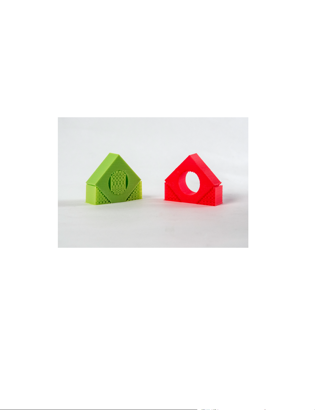
Cura LulzBot Edition
This can be helpful for saving expensive support material such as
soluble or break away support.
• Support placement will determine how support is generated.
Everywhere will build support everywhere, including within the
object. Touching build plate will build support material just
between the build plate and the object, ignoring interior holes of
the object. (Fig. 2.18, page 60)
Figure 2.18: Dierent Support Options
Support Overhang Angle
The support overhang angle will work to limit what areas of the object are
support and what are not. A 90 degree setting will only support objects
that are parallel to the build plate, while a 0 degree option will support
everything. A good recommended starting point is 45-60 degrees for most
laments.
60
Page 61

2.15. SUPPORT TAB SETTINGS
Support Pattern
As with inll, there are dierent patterns for support generation available.
Be sure to check your layer view before printing to ensure support placement is where it is needed, and not where it is not.
Support Density
The support density setting will determine how dense your support structures are. A more dense support structure will better support your object,
but will be harder to remove post print. When setting a support density
percentage, the line distances will automatically be calculated. You can
override the automatic calculation, and specify support line distance if you
prefer.
Enable Support Brim
Support brim will place a solid layer underneath your support, greatly
increasing adhesion during the print. This is recommended when using
sparse or custom inll. By adjusting Support Brim Width or Support
Brim Line Count you can adjust how much brim is placed.
Support Infill Line Direction
Depending on model geometry, it may be benecial to specify an inll line
direction to ensure a well supported object, and reduce support material.
After dening a support direction, it is recommended to check layer view
before printing to ensure proper placement.
Support Distances
There are several support options that specify how far away your support
material is kept from your object. These settings will aect eciency
of support, as well as ease of removal. It is important to nd the right
combination for your specic needs.
• Support Z distance denes the gap between your support structure
and your model in the Z direction. A good starting point is one
layer thickness for same material support, and 0 for soluble and/or
61
Page 62

Cura LulzBot Edition
breakaway support material. You can also specify a separate gap for
the top and bottom of the support material.
• Support X/Y distance will determine the distance between the
support material and your object in the X/Y plane.
• Support distance priority will determine which support distance
overrides the other. If clean undersides for the support surface are the
most important factor, have Z override X/Y. If it is more important
to have clean vertical lines next to support, have X/Y override Z.
• Support stair step height will determine how support is built on
top of your model. This denes how far up your support will build
in Z before moving out in the X/Y direction. A good starting point
is twice your layer height.
• Support stair step width will determine how support is built on
top of your model. This denes how far out your support will build
in the X/Y direction before moving up in the Z direction.
• Support join distance denes the minimum distance how far
apart two portions of your object(s) are to combine support structures. This can help save material and ensure support is adhered for
small objects.
• Support horizontal expansion will add an oset to your support
in the X/Y plane. This can help ensure support is covering all areas
you require on your model. Check layer view before printing to ensure
proper placement.
• Support infill layer thickness determines how thick your inll
is for support material. This should always be equal to, or a multiple
of your layer height to avoid part collisions with the print head.
• Gradual support infill steps reduces support farther down from
the interface of the supported object. This setting will halve the
set support density each time it moves X layers below the interface
surface.
62
Page 63

2.15. SUPPORT TAB SETTINGS
Enable Support Interface
Support interface creates a separate section on top of the support material,
before supporting your object. This “interface” layer is designed to use a
dierent material such as break away support. By just printing the special
material at the interface, it allows one to use a cheaper material such as
PLA for a majority of the support structure. You can specify a "roof"
which will be at the top of your supports, or a "floor" which will be at
the base of the support structure. Activating fan speed override can
help set the interface in place, making support removal easier post print.
Tower Support Settings
Tower support will generate support material that expands outside the
section of print it is meant to support at the base, and become smaller once
getting closer to the support interface. This helps ensure a solid support
structure, preventing parts from coming loose mid print.
Tower Diameter
Tower diameter will dene how far the base of the support extends outside
of the object it is meant to support. A larger number here will help generate
more stable support, but will require more material to print.
Minimum Diameter
The minimum diameter setting will specify how wide the top of your
support structure is when interacting with the model. Set this to your
nozzle diameter (0.5 mm) to have the narrowest support top possible.
Tower Roof Angle
The tower roof angle will build from your tower diameter base up to
your minimum tower diameter at the specied angle. Higher numbers will
provide a more vertical “pointy” support structure, while lower numbers
will provide a more “at” support build up.
63
Page 64

Cura LulzBot Edition
2.16 Build Plate Adhesion Settings Tab
Build plate adhesion will allow you to modify how your object is adhered
to the plate, along with priming your extruder before the print. First you
will want to select what type of build plate adhesion technique to use. You
have four separate options to choose from.
Skirt
Skirt prints a single layer tall ring around your object, which is intended
to prime the extruder and ensure no missed extrusion when starting your
actual object. Once selected you can specify a distance to keep from the
base of your object, a specic number of lines to print, and/or specify a
minimum extrusion length for how much skirt to print.
Brim
Brim will print a single layer thick line that extends around the base of
your object. This increased surface area helps adhere the part to the build
plate when your object has a small contact area. As with the skirt option,
you can specify multiple items related to brim once this is selected. Default
settings are usually sucient to ensure adherence for most models.
Raft
The raft option will build up support material underneath your part, and
then print the entire object on this support material. This is extremely
helpful for objects that do not have a at surface. As with skirt and brim,
once selected you can customize every aspect of how the raft is printed
to suit your needs. Default settings are recommended as a good starting
point.
None
The none option will not use any build plate adhesion techniques, and go
straight to printing your object. If you wish to reach the full build volume
of your printer, you will need to select none here as Skirt, Brim, and Raft
use a portion of the total build volume.
64
Page 65

2.17. DUAL EXTRUSION SETTINGS TAB
2.17 Dual Extrusion Settings Tab
The dual extrusion settings tab contains two main options consisting of the
priming tower and the ooze shield.
Prime Tower
A prime tower generates a pillar to be printed at a specied location on
the build plate. The tool head will move to this location and print a layer
with the active nozzle after a tool head switch when using dual extrusion.
Once activating the prime tower, several new options appear.
• Circular prime tower will generate a round prime tower, which
helps adhesion compared to the square prime tower. When using the
prime tower, it is recommended to activate this setting.
• Prime tower size will dene how large the prime tower is, and thus
aect how much lament is extruded each time. 15 mm is a good
starting point to ensure priming and adhesion.
• Prime tower position will allow you to dene where the prime
tower is located in the X/Y plane. Be sure to check this location,
if it interferes with your object it will prevent slicing.
• Prime tower flow will increase or decrease the extrusion multiplier
while printing the priming tower. For some laments an increased
ow rate will be required for good adhesion.
• Wipe inactive nozzle on prime tower will generate an extra
travel move that wipes the inactive nozzle on the prime tower after
switching. With the independent dual nozzles on the TAZ Pro, it is
not recommended to use this option.
Ooze Shield
When the ooze shield is activated, it will generate a single wall (think
“shield”) around the outside of your object. This is printed with each nozzle
being used in dual extrusion, and is designed to prevent any “dripping”
lament from the nozzles before falling on your object. Once activated,
65
Page 66

Cura LulzBot Edition
you can specify the angle at which the shield is generated, as well as the
distance it is created from your object.
2.18 Mesh Fixes Settings Tab
The mesh xes settings tab contains settings for Cura to attempt to x
design les. It is important to note that Cura is not a CAD program,
and using these settings may have unintended consequences on your model
design. The best practice will always be to print an STL le that is a single
shell and has no manifold errors. Having multiple STL les in this format
will not be an issue either.
Union Overlapping Volumes
Union overlapping volumes will attempt to combine overlapping meshes
internally within your object. This can cause intentional internal cavities
to disappear.
Remove All Holes
Remove all holes will ignore all internal geometry of your model, and only
focus on the outside shape of the model.
Extensive Stitching
Extensive stitching will close any external holes of the mesh by connecting
them with the nearest polygon. This can require a lot of additional
processing time.
Keep Disconnected Faces
This setting will prevent Cura from attempting to x any issues with your
model. This should just be used as a last resort when unable to generate
gcode, and still at that point may not produce ideal results.
66
Page 67

2.19. SPECIAL MODES SETTINGS TAB
Merged Meshes Overlap
Merged meshes overlap will slightly overlap two models during dual extrusion to ensure good adhesion between the parts. Too large of a setting here
can lead to color bleed on dual parts.
Remove Mesh Intersection
Remove mesh intersection will cause Cura to remove areas where multiple
models overlap during dual extrusion.
Alternate Mesh Removal
Alternate mesh removal will alternate which model in the overlapping
section is being ignored. The eect is an interwoven intersection between
the two models.
2.19 Special Modes Settings Tab
The special modes section changes the basic way in which Cura will slice
and generate gcode for your model. These can have some interesting eects
for specic uses.
Mold
The mold option will print a negative of your model by generating a shell
around your model leaving the internal structure empty. This can be used
for pouring in a substrate later to set your 3D object within a mold.
Minimal Mold Width
The minimal mold width setting determines how thick your mold will be
around the outside of your object.
Mold Roof Height
The mold roof height determines how far above your object the mold will
print on horizontal surfaces. This will help give a more accurate model, as
drooping can occur on long horizontal bridging sections.
67
Page 68

Cura LulzBot Edition
Mold Angle
The mold angle will determine how rounded the outside of your mold is. A
90 degree setting will have it follow your model exactly, while a 0 degree
setting will be more round and use more material. A 40 degree setting is a
good starting point.
Surface Mode
Surface mode allows you to specify two separate settings from the normal
model geometry.
Surface Mode
Surface mode will ignore your inll, top layer, and bottom layer. This
prints an empty shell one wall thick, without a roof or base layer.
Both Mode
Both mode acts very similar to surface mode, however it will print a roof
and a base layer leaving a hollow shell of your object.
Spiralize Outer Contour
Spiralize outer contour is an excellent option for making aesthetic vases.
This mode will ignore the inll of your object and the roof of your model.
This will print a base layer, and once complete build a single shell wall of
your object. The Z axis will slowly move up as it prints the wall in a spiral
pattern, preventing any layer change lines.
Relative Extrusion
Relative extrusion will change the way gcode is generated. Instead of using
an absolute coordinate positioning system, it will use relative movements
from its previous location. This setting can be helpful when using the 3D
printer for custom processes.
68
Page 69

2.20. EXPERIMENTAL SETTINGS TAB
2.20 Experimental Settings Tab
The experimental settings tab is where new features are introduced, and
may not be 100% reliable. Please reach out to [email protected] with
any feedback or issues encountered when using these settings.
Tree Support
Tree support will generate tree like structures in order to support specic
locations of your print. This can help reduce support material usage, but
can greatly increase slicing time. Once activated, there are several options
to customize this support:
• Tree support branch angle determines the angle in which your
branches extrude from the base of the tree. Use a lower angle for
more vertical, stable supports. Use a higher angle for more reach of
the branches.
• Tree support branch distance denes the distance apart the
branches are when making contact with the model. A small number
will support better, but make the support harder to remove. It is
recommended to check layer view before printing to ensure proper
placement.
• Tree support branch diameter determines the minimum diameter
of the branch support. A larger diameter produces more stable
supports, but uses more material.
• Tree support branch diameter angle determines the angle at
which the branches increase towards the base. A 0 degree setting
here will mean the branches are the exact same diameter from build
plate to support.
• Tree support collision resolution determines the limit of the
supports hitting the model. A lower number here will provide more
accurate results, but greatly increases slicing time.
• Tree support wall thickness determines how thick the walls of
the tree support will be.
69
Page 70

Cura LulzBot Edition
• Tree support wall line count will allow you to dene thickness
of the tree support walls by number of walls instead of thickness.
Slicing Tolerance
Slicing tolerance helps dene how to slice walls that are being built up at
an angle. Middle takes the least slicing time, and will place the walls in
the middle of the previous layer. Inclusive will align the wall on the inner
portion of the previous layer’s wall. Exclusive will align the wall with the
previous layer’s outer wall, providing increased details but requires longer
processing time.
Infill Travel Optimization
Inll travel optimization will attempt to save time by changing the path of
inll. The amount of time saved greatly depends on model geometry and
inll pattern type.
Minimum Polygon Circumference
Minimum polygon circumference denes the smallest polygon that will
attempt to be sliced. Any polygons that have a smaller circumference
than set will be ignored.
Maximum Resolution
Maximum resolution denes the minimum length of a line segment generated while slicing. Smaller numbers provide greater resolution, but will
take additional time to process gcode.
Maximum Travel Resolution
Maximum travel resolution will determine the minimum travel line segment.
In general this setting should be just underneath your nozzle size.
70
Page 71

2.20. EXPERIMENTAL SETTINGS TAB
Break Up Support In Chunks
Break up support in chunks will allow you to skip lines in the Zig Zag
support pattern. This makes support easier to remove, but may not be as
stable. After activating this option support chunk size will dene how
often you skip a layer in millimeters and support chunk line count will
allow you to dene every X layer it will happen.
Enable Draft Shield
Enable draft shield will create a single wall (think “shield”) around your
object. The intent is to maintain heat from the printed object to enable
more uniform cooling, preventing warping. After being activated you can
dene how far away from your object the shield is, and how high it extends
around your object.
Make Overhang Printable
Make overhang printable will change the geometry of the model itself. This
will change any overhang angles to your set amount. It is recommended to
change your model geometry in the CAD program of your choice opposed
to this option.
Enable Coasting
This prevents extrusion from occurring near sharp corners and at the end
of layers, and allows the pressure of the nozzle to extrude the remaining
lament. This gives sharper corners, and prevents gaps and blobs at layer
changes.
• Coasting volume determines how much of the material should be
ignored at the end of a move or when changing directions. This
number should be near your nozzle diameter cubed.
• Minimum volume before coasting determines how much feed stock
must be taken into the extruder before enabling a coasting move. This
ensures enough pressure has been built up to prevent a gap in the
layer.
71
Page 72

Cura LulzBot Edition
• Coasting speed determines how fast your print head will move
during these moves. A slightly slower speed such as 90% is a good
recommended starting point.
Alternate Skin Rotation
Alternate skin rotation allows you to change your top and bottom inll
patterns. Usually the top and bottom layers are rotated at a 45 degree
diagonal, but this setting allows rotations along the X and Y axis.
Spaghetti Infill
Spaghetti inll is designed to print the inll sporadically, causing the inll
to curl up reducing print time. Once activated you can specify dierent
aspects of how the inll is generated. This setting produces weaker parts
and can be inconsistent between prints.
Enable Conical Support
Enabling conical support will make supports that have a small base, and
get larger once closer to the part they are supposed to support. After activating, you can dene the conical support angle and conical support
minimum width. This setting tends to be less reliable than other support
methods described previously.
Fuzzy Skin
Fuzzy skin creates a unique rough texture on the outside of your object.
This is accomplished by making several small passes at an angle to the wall
while printing. After activating you will be able to determine the skin
thickness and skin density. This setting provides cosmetic benets
only.
Flow Rate Compensation
Flow rate compensation is a setting used to compensate for the pressure
delay during retracts in Bowden systems. For direct drive systems such as
LulzBot 3D Printers this setting will not be required.
72
Page 73

2.20. EXPERIMENTAL SETTINGS TAB
Wire Frame Printing
Wire frame printing generates a wire frame of your object. This is
accomplished by moving upward in the Z direction while making X/Y
movements. After making an extrusion, it will move to a new location, drop
down in Z, and repeat the process. This will make weak, yet aesthetically
pleasing prints.
Use Adaptive Layers
Adaptive layers is an excellent setting that helps speed up print time while
preserving high detail curves. Adaptive layers will print thicker layers on
more vertical parts of your model, and thinner layers on more curved parts
of your model.
• Adaptive layers maximum variation will dene the largest layer
dierence allowed from the base layer and the top layer. A higher
number will decrease print times, but reduce overall aesthetic quality.
• Adaptive layers variation in step size will determine the
maximum change in layer height from one layer to the next.
• Adaptive layers threshold compares the tangent of the steepest
slope of your model to determine if a small layer should be used or
not. It is recommended to check layer prior to printing to ensure
desired results.
Overhang Wall
The overhang wall settings will allow one to set separate settings for just
wall overhangs. You can dene wall overhang angle and wall overhang
speed. Setting the angle to 90 degrees will prevent using this setting.
Enable Bridge Settings
Bridge settings is one of the most powerful and useful options within
experimental settings. A bridging move is when the extruder connects one
“post” to another “post”, with no material underneath to support this from
drooping due to gravity. When this setting is activated, you can control
how the extruder moves and cools in these sections only.
73
Page 74

Cura LulzBot Edition
• Minimum Bridge Wall Length determines the minimum length of a
bridging move to use adjusted settings.
• Bridge Skin Support threshold determines if skin should use
bridging overrides. If skin is supported by less than X% it will use
bridge overrides.
• Bridge Wall Coasting determines what percentage of your coasting
value to use before entering a bridging move.
• Bridge Speeds will control how quickly your printer and extruder
are moving during dierent sections of the bridging moves. Faster
moves generally provide better bridge sections.
• Bridge Flow % determines what ow rate to use in dierent sections
of the bridge. A lower ow rate such as 90% helps provide cleaner
bridges.
• Bridge Density % determines how dense certain portions of the
bridging moves are. Values less than 100% may leave gaps between
the lines.
• Bridge Multiple Layers allows you dene the second and third
layer of a bridge individually. This can reduce time by speeding up
moves, as the rst layer of the bridge will support the next.
74
Page 75

Maintaining Your 3D Printer
Page 76

Maintaining Your 3D Printer
3.1 Overview
Little maintenance is required keep your LulzBot TAZ Pro 3D printer
running. Depending on your rate of use you will want to perform a quick
check of your printer every 2 to 4 weeks. The following maintenance
guidelines will keep your printer printing quality parts.
3.2 Smooth Rods
Wipe the smooth steel rods with a green scrub pad, clean cloth, or
paper towel. The linear bushings leave a solid lubricant that builds
up over time. Squeaking noises while the printer is in operation is
likely a sign that the smooth rods need to be cleaned. NOTE: Never
apply any lubricant or cleaning agent to the smooth rods as
the bushings are self-lubricating.
3.3 PEI Print Surface
The PEI print surface is the key to well-balanced part adhesion and release.
While long-lived, it will need to be replaced periodically and is considered
a consumable item. To clean the PEI print surface, wipe clean with
watered-down Isopropyl Alcohol 10:1 IPA to water ratio and a clean
cloth. If you encounter prints lifting from the PEI surface, use ne grit
sandpaper, typically 2000-2500 grit to clean the PEI print surface. We
do not recommend printing on bare glass, as it can lead to glass bed
damage or failure. Never use acetone to clean the PEI print surface as
doing so can damage the lm. You can nd our maintenance and guides
here: https://www.lulzbot.com/learn/tutorials
3.4 Hobbed Bolt
Filament is pulled through the extruder by a hobbed (or toothed) bolt.
After repeated use, the teeth of the hobbed bolt can become lled with
plastic. Using the dental pick from the printer kit, clean out the hobbed
bolt teeth. If an extruder jam ever occurs, remove the plastic lament
from the extruder and clean out the hobbed bolt.
76
Page 77

3.5. BELTS
3.5 Belts
Over long periods or after extensive relocating of the printer you may need
to re-tighten the belts on your 3D printer. For the X-axis, using the 2.5mm
hex driver, loosen one of the belt clamps. The belts clamps are located on
the X-axis carriage. To loosen the belt clamp, loosen the M3 screws on the
clamp. Using the needle nose pliers, pull the belt tight. While holding the
belt tight, tighten down the M3 screw. The Y-axis belt can be tightened
using the same steps as the X-axis using the belt clamps found on the
bottom of the Y-axis plate. Make sure not to over tighten the belts as this
can cause binding and prevent full movement.
The Z axis belts used are continuous, and should not need tensioning.
If they do require tensioning, use your M5 driver to tighten the screw on
the top of your Z uppers.
3.6 Hot End
The hot end should be kept clean of extruded plastic by removing melted
plastic strands with tweezers. If melted plastic builds up on the hot end
nozzle you can clean it by raising the head o the build plate, and heating
to extrusion temperature. Using a thick leather glove and a blue shop towel,
carefully wipe o the outside of the hot end. Never use a metal wire brush
on your hot end as it can potentially lead to a short on the electronics
board.
3.7 Nozzle Wiping Pad
Over time the nozzle wiping pad will become lled with plastic residue.
The pad can be ipped over once and will need to be replaced when
both sides are covered in plastic. Replacement nozzle wiping pads are
available in our online store at http://LulzBot.com. Do not attempt to
use a plastic or polymer based wiping pad as it can melt, rather than
clean the nozzle. A metal wiping pad should never be used, as it
can cause a short on the electronics board. If the nozzle is not
clean, the bed-level calibration process will fail.
77
Page 78

Maintaining Your 3D Printer
3.8 Bed Leveling Washers and Calibration
Cube
Keep the washers and calibration cube mounted on the Y axis plate clean
and dust free by wiping them periodically with Isopropyl Alcohol (IPA), or
a clean dry cloth. If the bed leveling washers are not clean during the bed
calibration process the print surface or tool head may be damaged. If the
calibration cube is not clean during the oset or backlash probing, you can
get inaccurate results and possibly damage your tool head. Never attempt
to clean the bed leveling washers or calibration cube during the probing
sequence as it may lead to personal injury.
3.9 Cooling Fans
Every 2-4 weeks carefully clean your hot end cooling fan by powering o
the 3D printer and unplugging the tool head from the extruder harness.
Gently blow any dust away with short bursts from a can of compressed air.
3.10 Control Box
If dust is evident on the control box vents, unplug the printer and use
short bursts of compressed air to blow out any dust. Once a quarter it is
recommended to completely open the electronics cover, and blow away any
debris on the board using short bursts from a can of compressed air.
78
Page 79

Advanced Usage
Page 80

Advanced Usage
4.1 Intro
After you become familiar with printing using the default settings, a few
advanced techniques may help in getting better and more consistent prints
from the LulzBot TAZ Pro 3D printer. Some of these instructions are items
and materials not included with the TAZ. With any of these additional
items or materials, follow safety and usage guidelines as instructed by the
manufacturer.
4.2 Changing nozzles
Hot End related issues will not be covered under warranty after nozzle
changes. Purchase a tool head from LulzBot.com with an alternate nozzle
diameter for quick, easy, and simple changes.
Due to the specic torque of 30 inch pounds required to tighten the
nozzle when removed, removing the nozzle is not recommended. Failure to
properly tighten the nozzle to the specic recommended torque may lead
to leaks or damage if over-tightened.
4.3 Bed Adhesion
You may nd that during printing, printed parts lift o the print surface
on the corners. If you are seeing this, turning on Brim in Cura will help
increase the surface area of the print, improving part adhesion. If the
corners of the part still lift, clean the PEI surface with IPA/ Isopropyl
Alcohol and sand the surface with ne grit (2000-3000) sandpaper.
Glue stick/PVA Glue solution
While almost all 3D printing laments will adhere well to the PEI print
surface, Nylon-, Polyester-, polycarbonate-, and Amphora™-based lament
print adhesion can be improved with the application of an unscented PVAbased glue solution/glue stick. Flexible laments such as NinjaFlex®and
SemiFlex™can adhere too well and require an application of PVA-based
glue to the print surface for easy print removal. Failure to properly treat
the print surface can lead to a permanent bond to the PEI print surface
and will require replacement which may not be covered under warranty.
80
Page 81

Troubleshooting
Page 82

Troubleshooting
5.1 Troubleshooting
Error Codes
The following error codes may be displayed within the Cura LulzBot
Edition control window, or displayed on the Graphical LCD controller.
MINTEMP
The thermistor for one of the hot ends is reading 0°C or below while
attempting to heat. If your printing area is at room temperature, this
is likely the result of a break in the thermistor wiring or poor connection.
MAXTEMP
The thermistor reading has gone above the maximum temperature set in
the rmware (300°C for the TAZ Pro.) This could be caused by shorted
thermistor wires, a failing heater or poorly set PID values causing the hot
end to overrun its set temp.
Thermal Error E1
Triggered by the primary hot end dropping in temperature beyond a
threshold set in the rmware. It can be caused by a failing heater cartridge
or excessive fan on the hot end, or in a worst case scenario, by the thermistor
coming out of the tool head during printing.
Thermal Error E2
Triggered by the secondary hot end dropping in temperature beyond a
threshold set in the rmware. It can be caused by a failing heater cartridge
or excessive fan on the hot end, or in a worst case scenario, by the thermistor
coming out of the tool head during printing.
Thermal Error Bed
This is triggered by the bed dropping in temperature beyond a threshold
set in the rmware. It can be caused by a failing bed heater or wiring or
excessive fan on the bed, or in a worst case scenario, by the thermistor
coming out of the bed during printing (unlikely).
82
Page 83

5.1. TROUBLESHOOTING
PROBE FAIL CLEAN NOZZLE
This means that the printer has detected a failed wiping routine and has not
been able to correct itself with 3 rewipe sequences. This is usually caused
by the wiping temps not being correct for the material that’s coating the
nozzle. Resolution:
• Use the correct Quickprint prole in Cura LulzBot Edition.
• If you’ve just switched from a material that is printed at a higher
temperature to one that prints at a lower temperature, try heating
the hot end to the wipe temperature recommended in that material’s
Quickprint prole.
A printed wiper pad handle can make this much easier:
http://devel.lulzbot.com/wiper_pads/wiper-pad-handle
HEATING FAILED
The hot end was not able to reach the target temperature.
Filament Runout Detected
Your TAZ Pro comes equipped with a dual lament runout detector. If
the lament runs out, or becomes stripped this error will appear. Ensure that lament is loaded and owing properly, with a clean hobbed
bolt before resuming print. If a number of false positives are occurring, lament runout detection can be disabled via the LCD screen.
Go to Menu > Advanced Settings > Filament > Runout Detection >
Turn down to ``0" or until it states ``Disabled".
83
Page 84

Page 85

Hardware and Software Source Code
Page 86

Hardware and Software Source Code
The LulzBot TAZ Pro 3D printer is a Free Software and Open
Source Hardware design. All of the source les are available at
http://download.lulzbot.com/TAZ including:
• The latest version of this document, with LATEX source code.
• 3D models and print les for all of the printed parts in .stl, .gcode,
and other original source les.
• 3D calibration objects and random novelties.
• Design les for all electronics and machined parts.
– Genuine E3D Hot Ends
– Archim electronics schematic
– Various spec sheets
• Bill of materials including every part needed to build the printer.
– TAZ
– Genuine E3D Hot Ends
• Drawings of components.
– Aluminum extrusions
– Genuine E3D Hot Ends
– Bed plate
• Software binaries and source code for GNU/Linux and others.
– Cura LulzBot Edition
– Marlin
• Cura LulzBot Edition Print Proles (vendor- and lament-specic
conguration les).
– LulzBot.com/Cura
86
Page 87

3D Printer Support
Page 88

3D Printer Support
7.1 LulzBot
For common technical support questions for your LulzBot TAZ 3D printer
please visit LulzBot.com/support. Also, visit Forum.LulzBot.com for
support and tips from the LulzBot 3D printer community. If you have
further questions, e-mail our support team at [email protected]. The
Technical Support Team is available 24 hours a day, seven days a week
except when closed due to weather or holiday. Please completely read this
manual before contacting for support questions or help. The latest version
of this information guide is also available at LulzBot.com/Download. You
can also nd more information including images, videos, and updated
versions of this manual at LulzBot.com/Support.
7.2 Support
Email: [email protected]
Phone: +1-970-377-1111 x610
7.3 Regional Phone Numbers
The full list of regional phone numbers is available at
LulzBot.com/contact-us A brief list can be found in this guide in
Section 9.3.
7.4 Community
Community Support and Resources
• LulzBot 3D printer forum: Forum.LulzBot.com
• LulzBot Online Community: LulzBot.com/community
88
Page 89

Warranty Information
Page 90

Warranty Information
8.1 Warranty
Warranty information for your LulzBot TAZ 3D printer can be found at
https://www.lulzbot.com/support/warranty
Extended Warranty
Optional extended warranty terms are available for purchase at
https://www.lulzbot.com/store/parts/lulzbot-taz-extended-warranty.
8.2 Modication Warning
WARNING: At Aleph Objects, Inc we respect your freedom to modify
your LulzBot desktop 3D printer. However, any modifications or
attempted repairs that cause damage are not covered under
the Warranty. Questions? Contact Technical Support by emailing
[email protected] or by calling +1-970-377-1111.
90
Page 91

Contact Information
Page 92

Contact Information
9.1 Support
Email: [email protected]
Phone: +1-970-377-1111 x610
9.2 Sales
Email: [email protected]
Phone: +1-970-377-1111 x600
9.3 Regional Phone Numbers
A complete list of regional phone numbers is available at
LulzBot.com/contact-us.
• Australia (Sydney ): +61-280730598
• Argentina (Buenos Aires ) : +54-1152175948
• Belgium : +32-78480607
• Brasil (Sao Paulo ) : +55-1123911886
• Canada (Toronto): +1-647-560-0006
• China (Shenzhen): +86-75586243890
• Czech Republic (Prague ): +420-255790505
• Denmark : +45-78791123
• Finland (Helsinki ): +358-942417761
• Great Britain (London ) : +44-2036033166
• Israel (Jerusalem ) : +972-25609370
• Mexico (Mexico City ) : +52-5541708259
• Netherlands (Amsterdam ) : +31-208004975
• New Zealand (Auckland ): +64-99143129
92
Page 93

9.4. WEBSITES
• Norway (Oslo ) : +47-21983874
• Spain (Madrid ): +34-912901413
• Sweden (Stockholm ): +46-812410612
• Switzerland (Zurich ) : +41-445087565
• United States (Loveland): +1-970-377-1111
9.4 Websites
Aleph Objects, Inc., the makers of the LulzBot brand of 3D Printers:
www.AlephObjects.com
LulzBot 3D Printers and parts:
www.LulzBot.com
Forum.LulzBot.com
93
Page 94

Page 95

Index
Symbols
.gco, 12
.gcode, 12
3D models, 19
3D printed parts, 86
A
ABL, 33
acceleration control, 55
acetone, 77
active print, 30
adaptive layers, 73
address, 92
advanced techniques, 80
alternate extra wall, 41
alternate mesh removal, 67
alternate skin rotation, 72
aluminum extrusions, 86
AMF, 19
Archim, 78, 86
Australia, x
auto-leveling, 78
automatic bed leveling, 33
avoid printed parts when travel-
ing, 56
B
backlash fading distance, 39
bed adhesion, 80
bed level compensation, 33
bed plate, 86
belts, 77
bill of materials, 86
Blender, 13
blowers, 78
both mode, 68
BotQueue, 14
bottle, 80
break up support in chunks, 71
bridge settings, 73
brim, 19, 64, 80
brim speed, 55
build plate adhesion, 19, 64
build plate temperature, 51
burns, viii
bushings, 76
C
CAD, 13
calibration, 86
combing mode, 56
community support, 88
compensate inner wall overlap, 41
compensate outer wall overlap, 41
congs, 86
conical support, 72
connect, 31
connect inll lines, 46
95
Page 96

INDEX
console, 31
contact, 92
contact info, 92
control, 31
cooling settings tab, 57
Cura, 16
Cura LulzBot Edition, 16, 86
custom supports, 24
D
damage, 90
default printing temperature, 49
diameter, 51
disconnect, 31
download, 86
dual extrusion settings tab, 65
E
E3D hot end, 86
electronics, viii, 78, 86
enable coasting, 71
enable draft shield, 71
enable retraction, 52
equalize lament ow, 55
Error Codes, 82
experimental settings tab, 69
extended warranty, 90
extensive stitching, 66
extra skin wall count, 44
extruder, viii
extruder assignment, 25
extruder jam, 76
extruder troubleshooting, 76
extrusion cool down speed modi-
er, 51
extrusion fan settings, 57
F
failed repair, 90
fan, 78
FCC, ix
lament, 17
lament runout, 83
lament vendors, 17
ll gaps between walls, 42
lter out tiny gaps, 42
nal printing temperature, 50
rst print, 33
ow, 52
ow rate compensation, 72
forums, 88
FreeCAD, 13
Freenode, 88
full color LCD, 34
full settings, 35
fuzzy skin, 72
G
g-code, 12
GCODE, 12
gcode, 86
generate support, 59
glass, 76, 77
GLCD, 34
glue stick, 34, 80
GNU/Linux, 12–14
gradual inll step height, 48
gradual inll steps, 48
graphical LCD controller, 34
H
hardware, 86
hazards, viii
heater block, viii
heating, 31
high detail, 18
high resolution, 80
96
Page 97

INDEX
high speed, 18
hobbed bolt, 76
horizontal expansion, 42
hot end, 77, 80, 86
I
ICES, x
ignore small z gaps, 43
inll, 18, 44
inll before walls, 48
inll density, 45
inll extruder, 45
inll layer thickness, 48
inll line directions, 47
inll line multiplier, 47
inll line width, 38
inll oset, 47
inll overlap percentage, 47
inll patterns, 45
inll speed, 54
inll support, 48
inll travel optimization, 70
inll wipe distance, 47
initial layer height, 37
initial layer line width, 38
initial layer speed, 55
initial printing temperature, 50
inner wall extruder, 39
inner wall line width, 38
inner wall speed, 54
installation, 16
intermittent extrusion, 76
IPA, 80
IRC, 88
ironing, 44
Isopropyl Alcohol, 76
isopropyl alcohol, 80
J
jerk control, 55
K
keep disconnected faces, 66
keep heating, 51
L
latex, 86
lay at, 22
layer height, 17, 37
layer start, 56
layer view, 28
LCD, 34
leveling, 78
lift head, 58
line width, 38
load model, 19
lubricant, 76
M
macOS, 12
maintenance, 76
make overhang printable, 71
manual control, 31
Marlin, 86
material selection, 17
material settings tab, 49
MatterControl, 14
maximum resolution, 70
maximum retraction count, 53
maximum skin angle for expan-
sion, 49
maximum travel resolution, 70
maximum z speed, 55
MAXTEMP, 82
merged meshes overlap, 67
mesh xes, 66
minimal mold width, 67
97
Page 98

INDEX
minimum diameter, 63
minimum layer speed, 58
minimum layer time, 58
minimum polygon circumference,
70
minimum wall ow, 41
MINTEMP, 82
mirror, 22
modication, 90
mold, 67
mold angle, 68
mold roof height, 67
monitor tab, 29
movement, 31
multiple printers, 33
multiply object, 26
N
New Zealand, x
NinjaFlex, 80
novelties, 86
nozzle, 77, 80
nozzle cooling fan, 78
nozzle switch retraction distance,
54
nozzle switch retraction speed, 54
nozzle wipe, 77
number of slow layers, 55
Nylon, 80
O
OBJ, 19
OctoPrint, 14
ooze shield, 65
OpenSCAD, 13
operating system, 12
optimize wall printing order, 41
orientation, 19
OS X, 12–14
outer before inner walls, 41
outer wall extruder, 39
outer wall inset, 41
outer wall line width, 38
outer wall speed, 54
outer wall wipe distance, 40
overhang wall, 73
P
part removal temperature, 51
pause print, 33
pausing the printing process, 33
PEI, 76, 80
PEI surface, 76
per model settings, 23
phone number, 92
Polycarbonate, 80
power supply, viii
predened commands, 32
prime tower, 65
print cooling, 57
print cooling fan, 78
print proles, 86
print speed, 54
print thin walls, 42
printer host, 14
printer hosts, 12
printing from USB, 33
printing temperature, 49
printing temperature initial layer,
50
probe, 78
PROBE FAIL CLEAN NOZZLE,
83
probe temperature, 49
probing, 78
PVA, 80
98
Page 99

INDEX
Q
quality settings, 36
quick print prole, 17
R
raft, 19, 64
recommended print settings, 16
relative extrusion, 68
remove all holes, 66
remove mesh intersection, 67
removing a print, 35
RepRap, 88
reset, 22
resolution, 17
retract at layer change, 52
retraction, 52
retraction distance, 53
retraction extra prime amount, 53
retraction speed, 53
rotating object, 21
S
school glue, 80
seam corner preference, 43
SemiFlex, 80
setting visibility, 36
shell settings, 39
skin expand distance, 49
skin overlap percentage, 47
skin removal width, 48
skirt, 19, 64
skirt speed, 55
skirt/brim line width, 38
slicers, 12
slicing, 12
slicing proles, 86
slicing tolerance, 70
smooth rods, 76
soften temperature, 50
software, 12, 14, 86
solid view, 26
source code, 86
source les, 14
spaghetti inll, 72
special modes, 67
speed settings tab, 54
spiralize outer contour, 68
standard quality, 18
standby temperature, 53
STL, 13, 14, 19, 86
support blocker, 24
support brim, 61
support density, 61
support distance settings, 61
support inll line direction, 61
support interface, 63
support material, 18
support options, 59
support overhang angle, 60
support pattern, 61
support tab settings, 59
surface mode, 68
T
t-glase, 80
technical support, 88
temperature, viii
temperature control, 30
temperature monitoring, 30
temperatures, 34
terms and conditions, 90
tetherless printing, 34
Thermal Error Bed, 82
Thermal Error E1, 82
Thermal Error E2, 82
threaded extension, 80
99
Page 100

top surface skin layers, 40
top/bottom extruder, 40
top/bottom line width, 38
top/bottom speed, 54
top/bottom thickness, 40
tower diameter, 63
tower roof angle, 63
tower support, 63
travel tab settings, 56
tree support, 69
U
union overlapping volumes, 66
USB, 33
USB cable, 33
V
view options, 26
INDEX
W
wall extruder, 39
wall speed, 54
wall thickness, 40
warnings, viii
warping, 80
warranty, 90
white glue, 80
Windows, 12–14
wipe temperature, 50
wiping pad, 77
wire frame printing, 73
wires, viii
X
X-ray, 27
Z
z hop, 57
z seam alignment, 42
100
 Loading...