

Page 1
TAZ 3.0 User Manual
Aleph Objects, Inc.
Page 2

LulzBotTMTAZ 3.0 User Manual
by Aleph Objects, Inc.
Copyrightc 2013 Aleph Objects, Inc.
Permission is granted to copy, distribute and/or modify this document under the terms
of the Creative Commons Attribution-ShareAlike 3.0 Unported license (CC BY-SA 3.0).
Published by Aleph Objects, Inc., 626 W 66th Street, Loveland, Colorado, 80538 USA.
For more information, call +1-970-377-1111 or go to www.LulzBot.com and
www.AlephObjects.com.
ISBN: 978-0-9893784-3-7 20131211
Page 3

Contents
WARNINGS
Safety Information · · · · · · · · · xi
Read Me First! · · · · · · · · · · · · · · · · · · · · · · · · · · · xii
Hazards and Warnings · · · · · · · · · · · · · · · · · · · · · · · xii
1 Setup Your Printer · · · · · · · · · 15
1.1 Hardware Setup · · · · · · · · · · · · · · · · · · · · · · · · 16
1.2 ABS & Acetone Solution Prep · · · · · · · · · · · · · · · · 32
2 Loading Filament · · · · · · · · · 33
3 3D Printer Software · · · · · · · · 37
3.1 Software Overview · · · · · · · · · · · · · · · · · · · · · · 38
3.2 Installing Drivers · · · · · · · · · · · · · · · · · · · · · · · 38
3.3 Printrun · · · · · · · · · · · · · · · · · · · · · · · · · · · · 38
3.4 Using Printrun · · · · · · · · · · · · · · · · · · · · · · · · 41
3.5 CAD and 3D Modeling Software · · · · · · · · · · · · · · · 45
4 Your First 3D Print · · · · · · · · · 47
4.1 Bed Leveling · · · · · · · · · · · · · · · · · · · · · · · · · · 48
4.2 Set Temperature · · · · · · · · · · · · · · · · · · · · · · · 52
4.3 Load Filament · · · · · · · · · · · · · · · · · · · · · · · · · 52
4.4 Home Printer · · · · · · · · · · · · · · · · · · · · · · · · · 53
4.5 Z Print Height · · · · · · · · · · · · · · · · · · · · · · · · · 54
4.6 Your First Octopus! · · · · · · · · · · · · · · · · · · · · · · 56
4.7 Remove Part · · · · · · · · · · · · · · · · · · · · · · · · · · 57
5 Slic3r · · · · · · · · · · · · 59
5.1 Introduction · · · · · · · · · · · · · · · · · · · · · · · · · · 60
5.2 Getting Slic3r · · · · · · · · · · · · · · · · · · · · · · · · · 61
5.3 First Print · · · · · · · · · · · · · · · · · · · · · · · · · · · 62
iii
Page 4

CONTENTS
5.4 Simple Mode · · · · · · · · · · · · · · · · · · · · · · · · · · 79
5.5 Expert Mode · · · · · · · · · · · · · · · · · · · · · · · · · 88
5.6 Configuration Organization · · · · · · · · · · · · · · · · · · 116
5.7 Repairing Models · · · · · · · · · · · · · · · · · · · · · · · 118
5.8 Advanced Topics · · · · · · · · · · · · · · · · · · · · · · · 119
5.9 Troubleshooting · · · · · · · · · · · · · · · · · · · · · · · · 128
5.10 Slic3r Support · · · · · · · · · · · · · · · · · · · · · · · · · 129
6 Printing with the Graphic LCD · · · · · · 131
6.1 GLCD Controller or Printrun Host? · · · · · · · · · · · · · 132
6.2 Multiple Connections · · · · · · · · · · · · · · · · · · · · · 132
6.3 Putting Print Files On the SD Card · · · · · · · · · · · · · 133
6.4 Printing with the Graphic LCD · · · · · · · · · · · · · · · 133
7 Maintaining Your 3D Printer · · · · · · 139
7.1 Overview · · · · · · · · · · · · · · · · · · · · · · · · · · · · 140
7.2 Smooth Rods · · · · · · · · · · · · · · · · · · · · · · · · · 140
7.3 Threaded Rods · · · · · · · · · · · · · · · · · · · · · · · · 140
7.4 PET Sheets · · · · · · · · · · · · · · · · · · · · · · · · · · 140
7.5 Hobbed Bolt · · · · · · · · · · · · · · · · · · · · · · · · · · 141
7.6 Software · · · · · · · · · · · · · · · · · · · · · · · · · · · · 141
7.7 Belts · · · · · · · · · · · · · · · · · · · · · · · · · · · · · · 141
7.8 Hot End · · · · · · · · · · · · · · · · · · · · · · · · · · · · 142
7.9 Electronics · · · · · · · · · · · · · · · · · · · · · · · · · · · 142
8 Advanced Usage · · · · · · · · · · 143
8.1 Intro · · · · · · · · · · · · · · · · · · · · · · · · · · · · · · 144
8.2 Changing nozzles · · · · · · · · · · · · · · · · · · · · · · · 144
8.3 ABS/Acetone Glue · · · · · · · · · · · · · · · · · · · · · · 145
8.4 Using 1.75mm Filament · · · · · · · · · · · · · · · · · · · · 145
9 Hardware and Software Source Code · · · · 149
10 3D Printer Support · · · · · · · · · 151
10.1 LulzBot · · · · · · · · · · · · · · · · · · · · · · · · · · · · 152
10.2 Community · · · · · · · · · · · · · · · · · · · · · · · · · · 152
11 Contact Information · · · · · · · · 153
11.1 Support · · · · · · · · · · · · · · · · · · · · · · · · · · · · 154
11.2 Sales · · · · · · · · · · · · · · · · · · · · · · · · · · · · · · 154
11.3 Websites · · · · · · · · · · · · · · · · · · · · · · · · · · · · 154
iv
Page 5

CONTENTS
Index · · · · · · · · · · · · · 155
Glossary · · · · · · · · · · · · 159
v
Page 6

List of Figures
1.1 Axes movement directions · · · · · · · · · · · · · · · · · · · · 16
1.2 Locate the four Y axis bolts · · · · · · · · · · · · · · · · · · · 17
1.3 Remove the four Y axis bolts · · · · · · · · · · · · · · · · · · 17
1.4 Locate the four Y axis mounts on the frame · · · · · · · · · · 18
1.5 Screw in and tighten the four Y axis bolts · · · · · · · · · · · 19
1.6 Connect the two connectors found at the rear of the Y axis · · 20
1.7
Wrap and tighten a zip tie around the Y axis wires to the Y axis
frame. · · · · · · · · · · · · · · · · · · · · · · · · · · · · · · · 21
1.8 Connect the two connectors on the left of the print bed · · · · 22
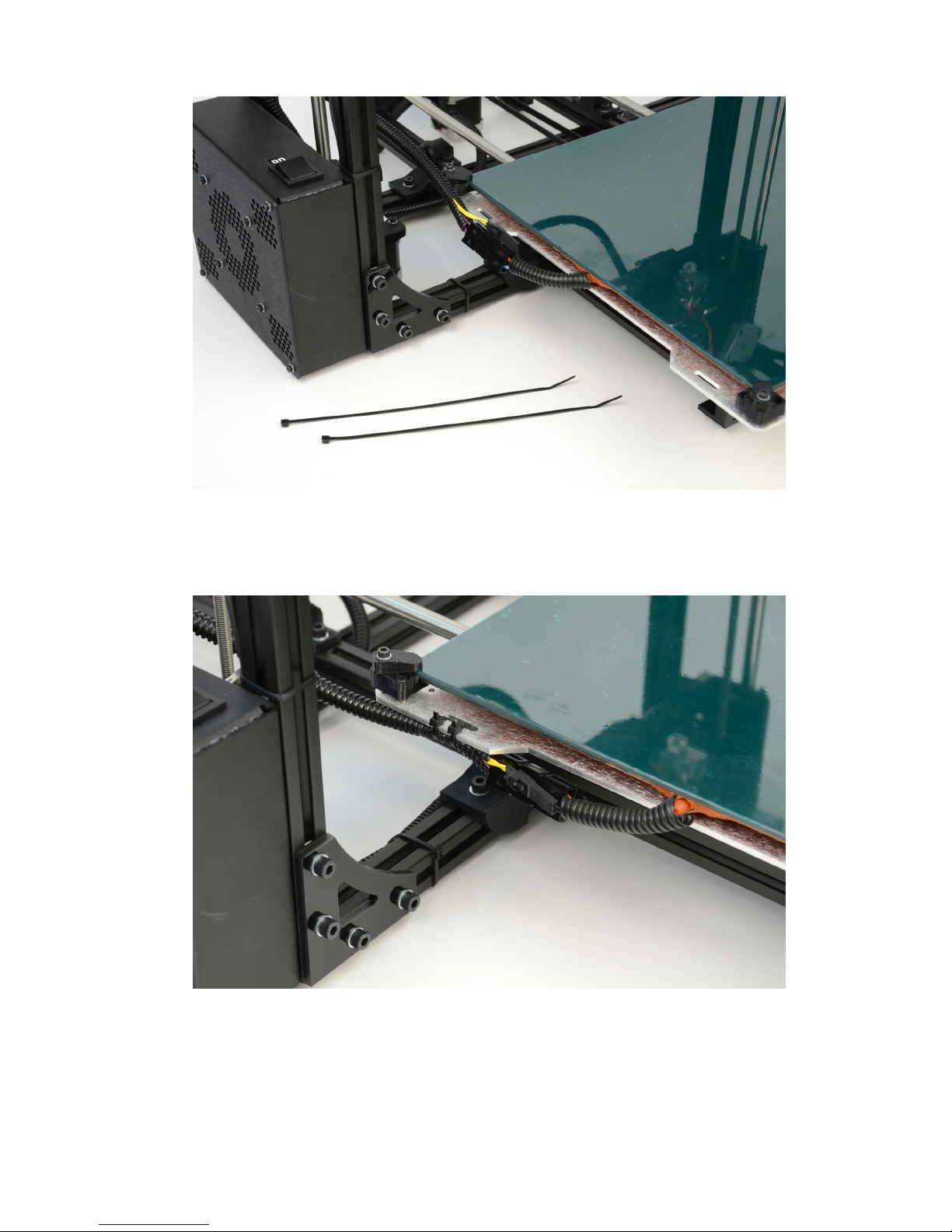
1.9 Locate the two zip ties found in the bag with the manual · · · 23
1.10
Tightly wrap the zip ties around the bed wires and through the
strain relief slot · · · · · · · · · · · · · · · · · · · · · · · · · · 23
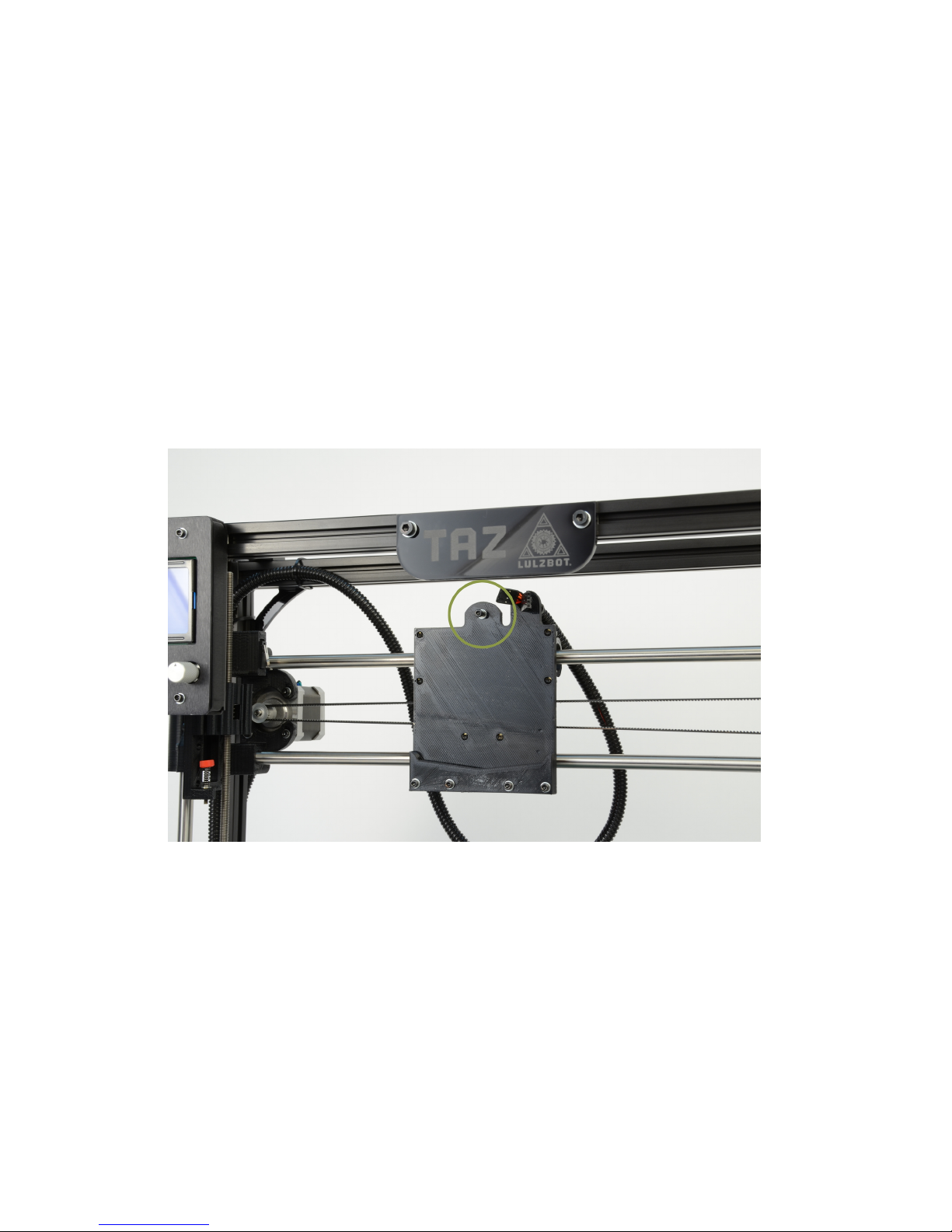
1.11 Remove the tool head screw · · · · · · · · · · · · · · · · · · · 24
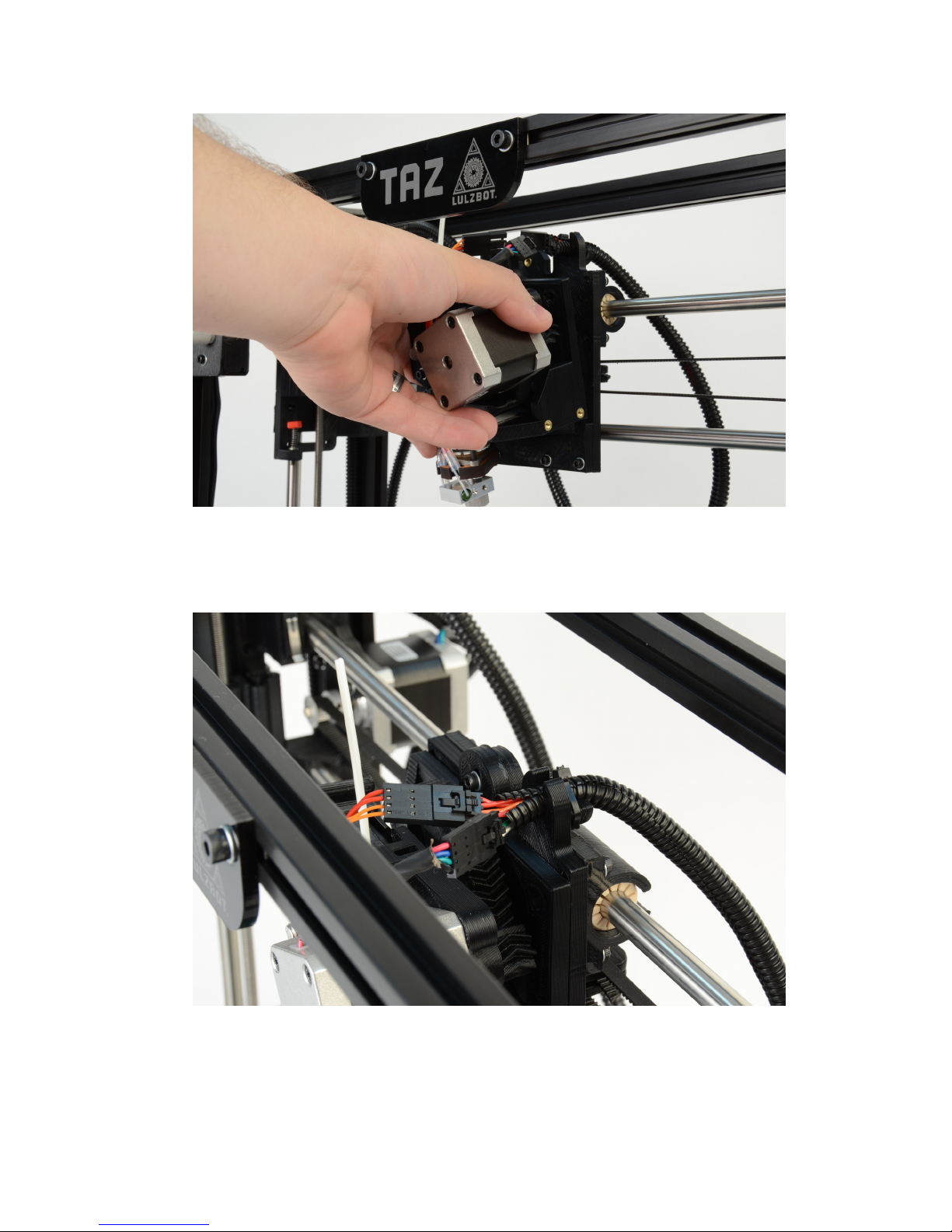
1.12 Mount the extruder tool head · · · · · · · · · · · · · · · · · · 25
1.13 Connect the two tool head connectors · · · · · · · · · · · · · · 25
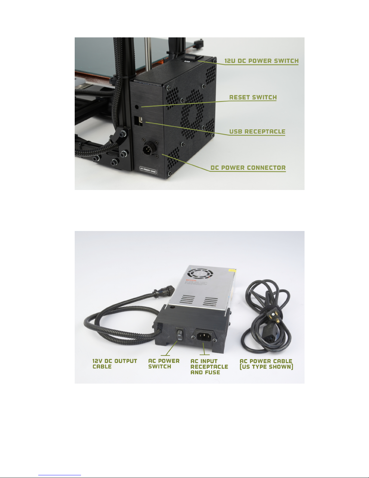
1.14 Power and USB receptacles · · · · · · · · · · · · · · · · · · · 27
1.15 Power supply · · · · · · · · · · · · · · · · · · · · · · · · · · · 27
1.16 24V DC Power supply plug and receptacle · · · · · · · · · · · 28
1.17 The power supply plug correctly plugged in · · · · · · · · · · · 28
1.18 Filament Guide · · · · · · · · · · · · · · · · · · · · · · · · · · 29
1.19 Filament Guide Mount · · · · · · · · · · · · · · · · · · · · · · 30
1.20 Filament Guide Setting · · · · · · · · · · · · · · · · · · · · · · 30
1.21 Axes movement directions · · · · · · · · · · · · · · · · · · · · 31
1.22 End stop locations · · · · · · · · · · · · · · · · · · · · · · · · 31
2.1 Filament reel arm · · · · · · · · · · · · · · · · · · · · · · · · · 34
2.2 Filament run through the guide · · · · · · · · · · · · · · · · · 35
3.1 Printrun application for 3D printer control · · · · · · · · · · · 39
3.2 Printrun · · · · · · · · · · · · · · · · · · · · · · · · · · · · · · 41
3.3 Printrun Functions · · · · · · · · · · · · · · · · · · · · · · · · 42
3.4 Movement Controls · · · · · · · · · · · · · · · · · · · · · · · · 43
4.1 Z end stop trigger · · · · · · · · · · · · · · · · · · · · · · · · · 48
4.2 Verifying the X and Y axis are square · · · · · · · · · · · · · · 50
vi
Page 7

List of Figures
4.3 Extruder idler release · · · · · · · · · · · · · · · · · · · · · · · 53
4.4 Extruder filament slot · · · · · · · · · · · · · · · · · · · · · · 54
4.5 Nozzle height · · · · · · · · · · · · · · · · · · · · · · · · · · · 55
4.6 Z end stop trigger · · · · · · · · · · · · · · · · · · · · · · · · · 55
4.7 First layer adhesion · · · · · · · · · · · · · · · · · · · · · · · · 56
5.1 Configuration Wizard: Welcome Screen · · · · · · · · · · · · · 64
5.2 Configuration Wizard: Firmware Type · · · · · · · · · · · · · 65
5.3 Configuration Wizard: Bed Size · · · · · · · · · · · · · · · · · 66
5.4 Configuration Wizard: Nozzle Diameter · · · · · · · · · · · · · 67
5.5 Configuration Wizard: Filament Diamter · · · · · · · · · · · · 68
5.6 Configuration Wizard: Extrusion Temperature · · · · · · · · · 69
5.7 Configuration Wizard: Bed Temperature · · · · · · · · · · · · 70
5.8 Configuration Wizard: End · · · · · · · · · · · · · · · · · · · 71
5.9 Shapesmith online CAD tool. · · · · · · · · · · · · · · · · · · 75
5.10 Plater · · · · · · · · · · · · · · · · · · · · · · · · · · · · · · · 76
5.11 Minimug model. · · · · · · · · · · · · · · · · · · · · · · · · · · 77
5.12 STL file loaded. · · · · · · · · · · · · · · · · · · · · · · · · · · 77
5.13 Preferences. · · · · · · · · · · · · · · · · · · · · · · · · · · · · 79
5.14 Simple Mode: Print Settings. · · · · · · · · · · · · · · · · · · 80
5.15 An example of insufficient top layers. · · · · · · · · · · · · · · 81
5.16 Creating a vase from a solid model. · · · · · · · · · · · · · · · 82
5.17 An example of an object printed with support material. · · · · 83
5.18 An example of brim. · · · · · · · · · · · · · · · · · · · · · · · 84
5.19 Simple Mode: Filament Settings. · · · · · · · · · · · · · · · · 85
5.20 Simple Mode: Printer Settings. · · · · · · · · · · · · · · · · · 86
5.21 Expert mode speed options. · · · · · · · · · · · · · · · · · · · 89
5.22 Infill pattern settings. · · · · · · · · · · · · · · · · · · · · · · · 91
5.23 Infill pattern: Line (344.51mm / 5m:20s) · · · · · · · · · · · · 91
5.24 Infill pattern: Rectilinear (350.57mm / 5m:23s) · · · · · · · · 91
5.25 Infill pattern: Concentric (351.80mm / 5m:30s) · · · · · · · · · 92
5.26 Infill pattern: Honeycomb (362.73mm / 5m:39s) · · · · · · · · 92
5.27 Infill pattern: Hilbert Curve (332.82mm / 5m:28s) · · · · · · · 92
5.28 Infill pattern: Archimedean Chords (333.66mm / 5m:27s) · · · 92
5.29 Infill pattern: Octagram Spiral (318.63mm / 5m:15s) · · · · · 93
5.30
Infill pattern comparison in a complex object. Left to Right:
honeycomb, line · · · · · · · · · · · · · · · · · · · · · · · · · · 93
vii
Page 8

List of Figures
5.31
Infill patterns at varying densities. Left to Right:
20%,40%,60%,80%. Top to Bottom: Honeycomb, Concentric,
Line, Rectilinear, Hilbert Curve, Archimedean Chords,
Octagram Spiral · · · · · · · · · · · · · · · · · · · · · · · · · · 94
5.32 Infill advanced settings. · · · · · · · · · · · · · · · · · · · · · · 95
5.33 Retraction settings. · · · · · · · · · · · · · · · · · · · · · · · · 96
5.34 Skirt settings. · · · · · · · · · · · · · · · · · · · · · · · · · · · 98
5.35 Cooling strategy. · · · · · · · · · · · · · · · · · · · · · · · · · 99
5.36 Cooling advanced settings. · · · · · · · · · · · · · · · · · · · · 101
5.37 Support structure options. · · · · · · · · · · · · · · · · · · · · 102
5.38 Minimug model, tilted 45◦. · · · · · · · · · · · · · · · · · · · · 103
5.39 Support infill pattern: Rectilinear · · · · · · · · · · · · · · · · 104
5.40 Support infill pattern: Rectilinear Grid · · · · · · · · · · · · · 104
5.41 Support infill pattern: Honeycomb · · · · · · · · · · · · · · · · 104
5.42 Example of pattern angle rotated 45◦. · · · · · · · · · · · · · · 105
5.43
Multiple extruder options - Printer Settings Tab (General). Note
the two extruders defined in the left-hand pane. · · · · · · · · 106
5.44 Multiple extruder options - Printer Settings Tab (Extruder). · 106
5.45 Plater with multiple filament options. · · · · · · · · · · · · · · 107
5.46 Multiple extruder options - Print Settings Tab. · · · · · · · · · 108
5.47 Multiple extruder options - Tool change G-code. · · · · · · · · 108
5.48 Extrusion widths options. · · · · · · · · · · · · · · · · · · · · 110
5.49 Example model highlighting use case for variable layer heights. 111
5.50 Example with normal layer height. · · · · · · · · · · · · · · · 112
5.51 Variable layer height options - Info. · · · · · · · · · · · · · · · 113
5.52 Variable layer height options - Layers. · · · · · · · · · · · · · · 114
5.53 Example with variable layer height. · · · · · · · · · · · · · · · 114
5.54 Example print with variable layer height. · · · · · · · · · · · · 115
5.55 Example with skipped layers. · · · · · · · · · · · · · · · · · · 115
5.56 Saving a profile. · · · · · · · · · · · · · · · · · · · · · · · · · · 117
5.57 Deleting a profile. · · · · · · · · · · · · · · · · · · · · · · · · · 117
5.58 FreeCAD part repair. · · · · · · · · · · · · · · · · · · · · · · · 118
5.59 Sequential printing options. · · · · · · · · · · · · · · · · · · · 119
5.60 The clearance cylinder around an extruder. · · · · · · · · · · · 120
5.61 Post-processing script option. · · · · · · · · · · · · · · · · · · 126
5.62
Example post-processing script to display Slic3r environment
variables. · · · · · · · · · · · · · · · · · · · · · · · · · · · · · 126
5.63 Example post-processing script to print each line to output. · · 127
viii
Page 9

List of Figures
6.1 GLCD Info Screen · · · · · · · · · · · · · · · · · · · · · · · · 133
6.2 Main menu · · · · · · · · · · · · · · · · · · · · · · · · · · · · 135
6.3 Configuration Menu · · · · · · · · · · · · · · · · · · · · · · · · 137
6.4 Configuration Menu · · · · · · · · · · · · · · · · · · · · · · · · 138
ix
Page 10

Page 11

WARNINGS
Safety Information
Page 12

WARNING!
Read Me First!
READ THIS MANUAL COMPLETELY BEFORE UNPACKING AND
POWERING UP YOUR PRINTER.
Hazards and Warnings
The TAZ 3D printer has motorized and heated parts. When the printer is
in operation always be aware of possible hazards.
Electric Shock Hazard
Never open the electronics case when the printer is powered on. Before
removing the electronics case cover always power down the printer and
completely turn off and unplug the power supply and allow the power
supply to discharge for at least 1 minute.
Burn Hazard
Never touch the extruder nozzle or heater block without first turning off
the hot end and allowing it to completely cool down. The hot end can take
up to twenty minutes to completely cool. Never touch recently extruded
plastic. The plastic can stick to your skin and cause burns. The heated bed
can reach high temperatures capable of causing burns.
Fire Hazard
Never place flammable materials or liquids on or near the printer when
powered or in operation. Liquid acetone and vapors are extremely flammable.
Pinch Hazard
When the printer is in operation take care to never put your fingers in the
moving parts including the belts, pulleys, or gears. Tie back long hair or
clothing that can get caught in the moving parts of the printer.
xii
Page 13

HAZARDS AND WARNINGS
Static Charge
Make sure to ground yourself before touching the printer, especially the
electronics. Electrostatic discharge can damage electronic components.
Ground yourself by touching a grounded source.
Age Warning
For users under the age of 18, adult supervision is recommended. Beware
of choking hazards around small children.
xiii
Page 14

Page 15

Setup Your Printer
Page 16
Setup Your Printer
1.1 Hardware Setup
1.
Your printer has been calibrated and tested, however, after unpacking
all of the components you will need to re-mount the Y axis onto the
frame and connect the bed and Y axis connectors. You will also
need to re-mount the extruder tool head. Please follow the steps
completely to make certain that the extruder tool head and Y axis
are re-mounted correctly. You will then be on your way to your first
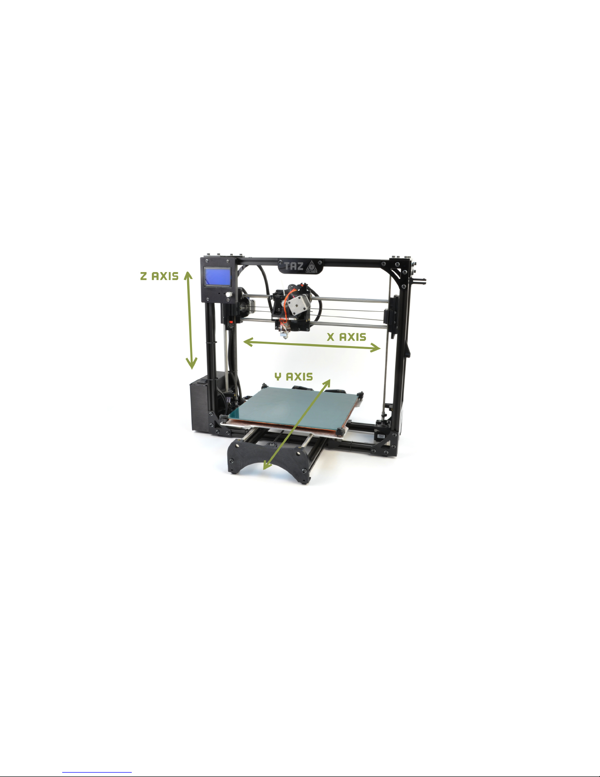
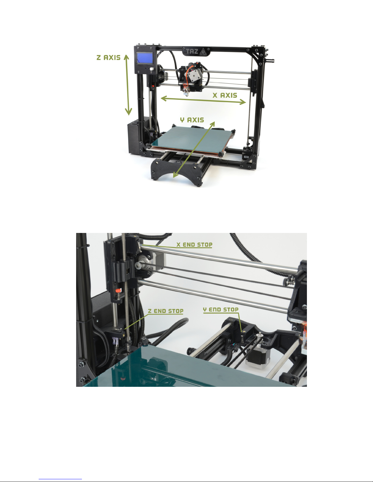
print. Use Fig. 1.1 to see which direction the three axes move, as the
following instructions will reference the X, Y, and Z axes.
Figure 1.1: Axes movement directions
2.
Place the TAZ frame and Y axis assembly on a flat and level surface.
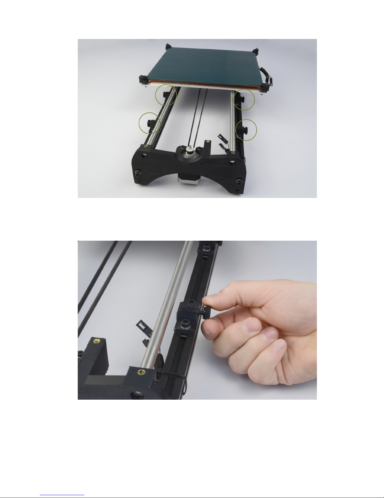
Move to the Y axis assembly and find the four Y axis bolts. The four
bolts located on the Y axis aluminum frame bars, have large plastic
knobs that allow the bolts to be easily turned by hand (Fig. 1.2, page
17). Turning counter clock-wise, remove each of the four Y axis bolts
and set aside (Fig. 1.3, page 17).
16
Page 17
1.1. HARDWARE SETUP
Figure 1.2: Locate the four Y axis bolts
Figure 1.3: Remove the four Y axis bolts
17
Page 18
Setup Your Printer
3.
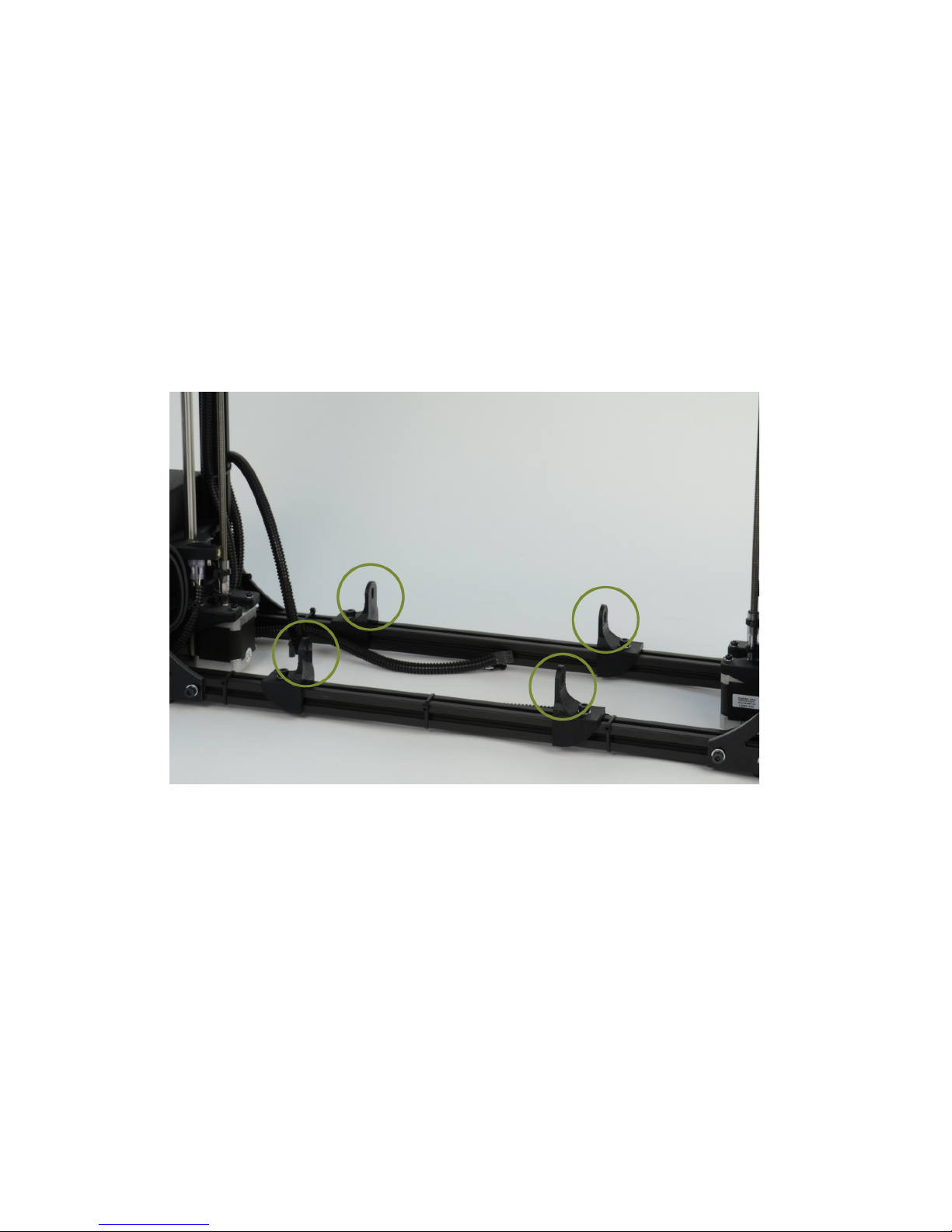
On the TAZ frame locate the four Y axis mount brackets shown in Fig.
1.4 (pg. 18). With the print surface facing up and the stepper motor
end of the Y axis facing back, slide the Y axis assembly in between
the Y axis mount brackets. The four Y axis mount brackets will line
up with the Y axis bolt holes on the Y axis assembly. Thread the four
Y axis bolts through the brackets, into the Y axis assembly (Fig. 1.5,
page 19). Before completely tightening the Y axis bolts make sure the
Y axis aluminum bars are pushed down against the TAZ frame lower
bars. While pushing on the black Y axis square extrusions tighten
the four Y axis bolts. The printer can now be set flat on the table.
Figure 1.4: Locate the four Y axis mounts on the frame
18
Page 19
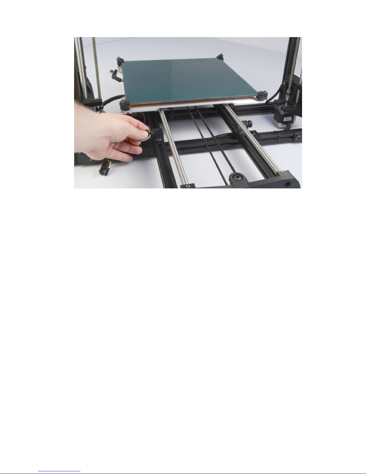
1.1. HARDWARE SETUP
Figure 1.5: Screw in and tighten the four Y axis bolts
4.
The next step of installing the Y axis is connecting the print surface
connectors and Y axis connectors. Pull the print bed completely to
the front of the printer to get access to the Y axis connectors. You
will find matching male and female 4 pin stepper motor connectors
and two pin end stop connectors. Connect the matching male and
female connectors (Fig. 1.6, page 20); make sure the connector’s lock
clicks to be sure that it is secured.
19
Page 20
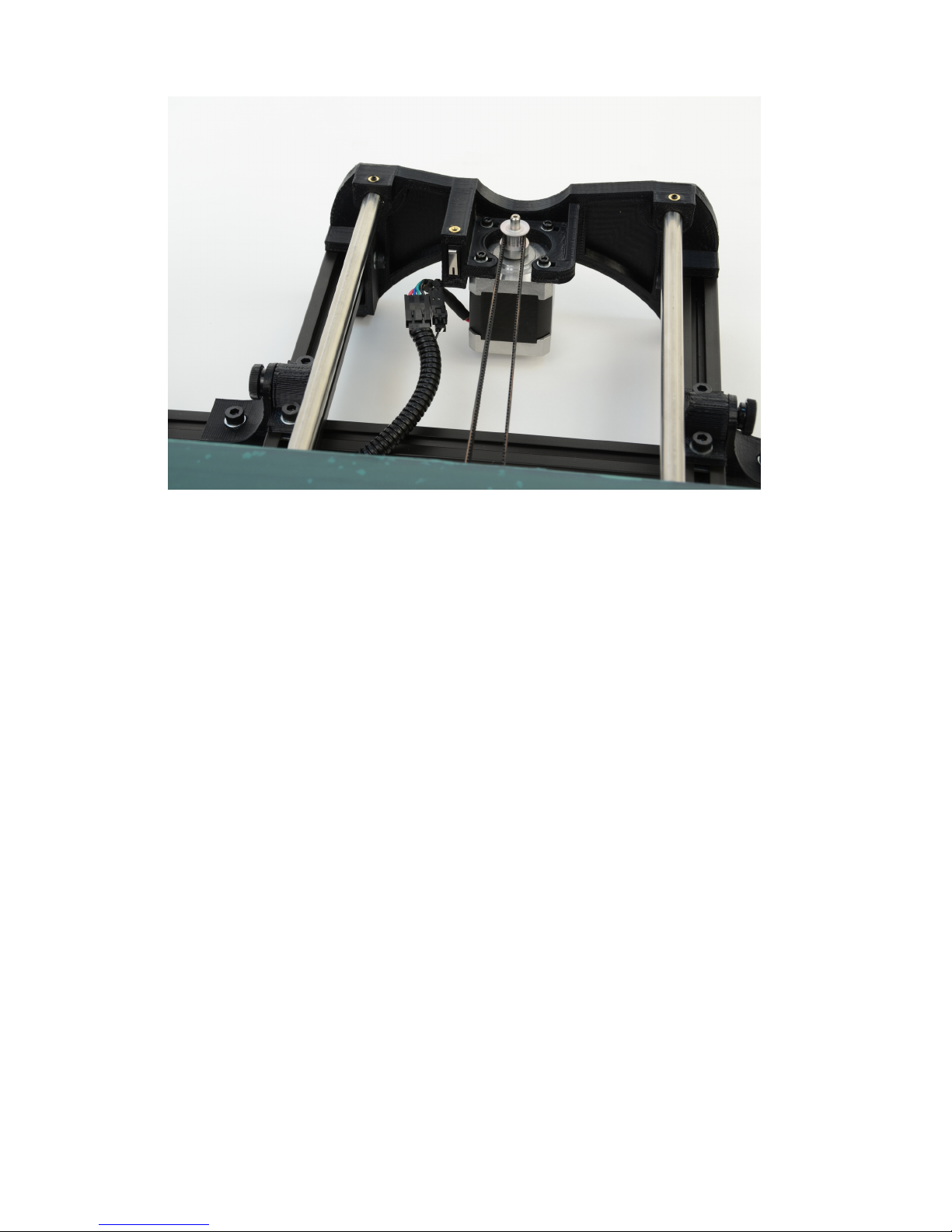
Setup Your Printer
Figure 1.6: Connect the two connectors found at the rear of the Y axis
5.
Locate one of the three small black zip ties that are included in the
documents bag. Wrap and tighten the zip tie around the Y axis wiring
and the black Y axis frame extrusion as shown in figure 1.7 (page 21).
20
Page 21
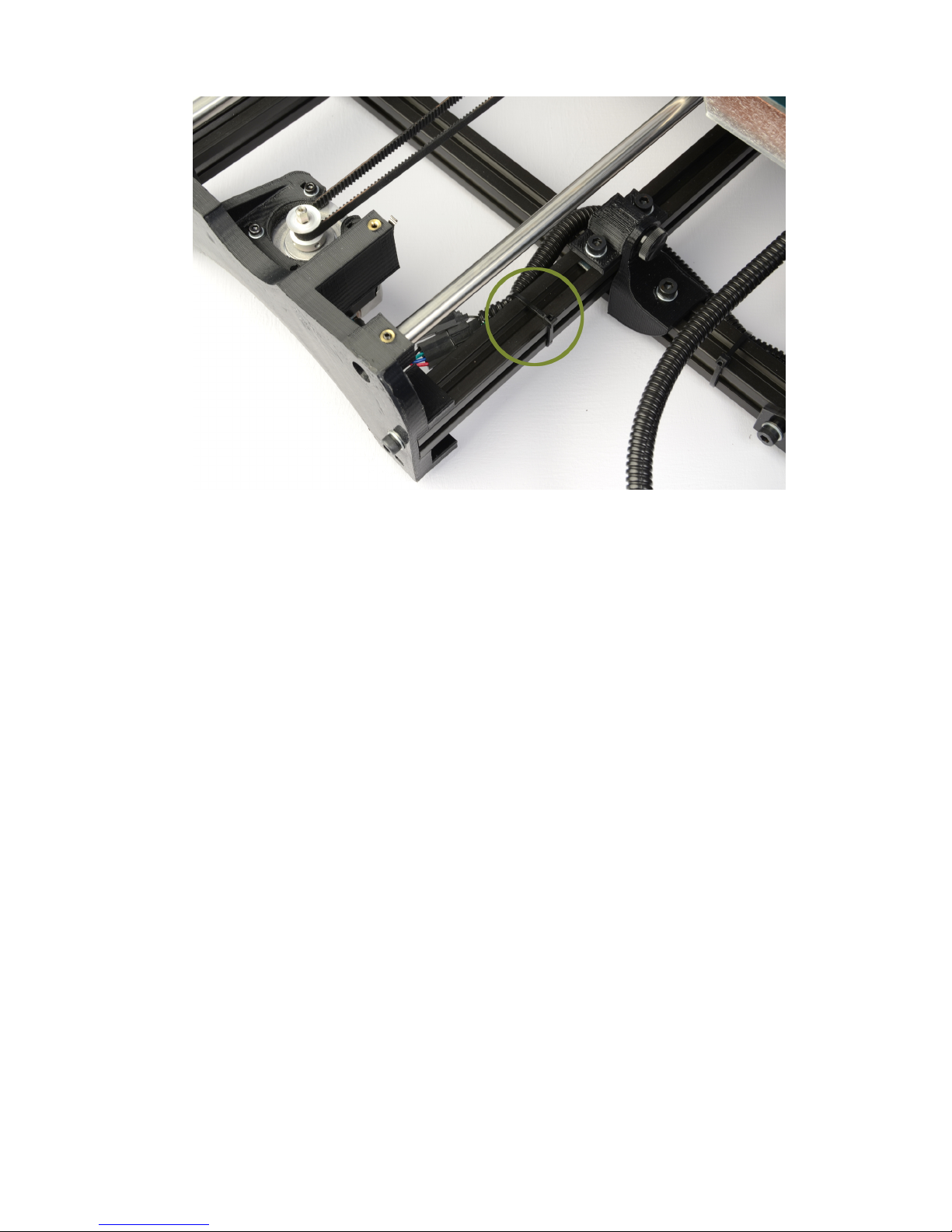
1.1. HARDWARE SETUP
Figure 1.7: Wrap and tighten a zip tie around the Y axis wires to the Y
axis frame.
6.
Locate the two connectors to the left of the print bed. Connect the
matching female and male large two pin heat bed connectors and the
small two pin thermistor connectors, again making sure the connectors
lock(Fig. 1.8, page 22).
21
Page 22
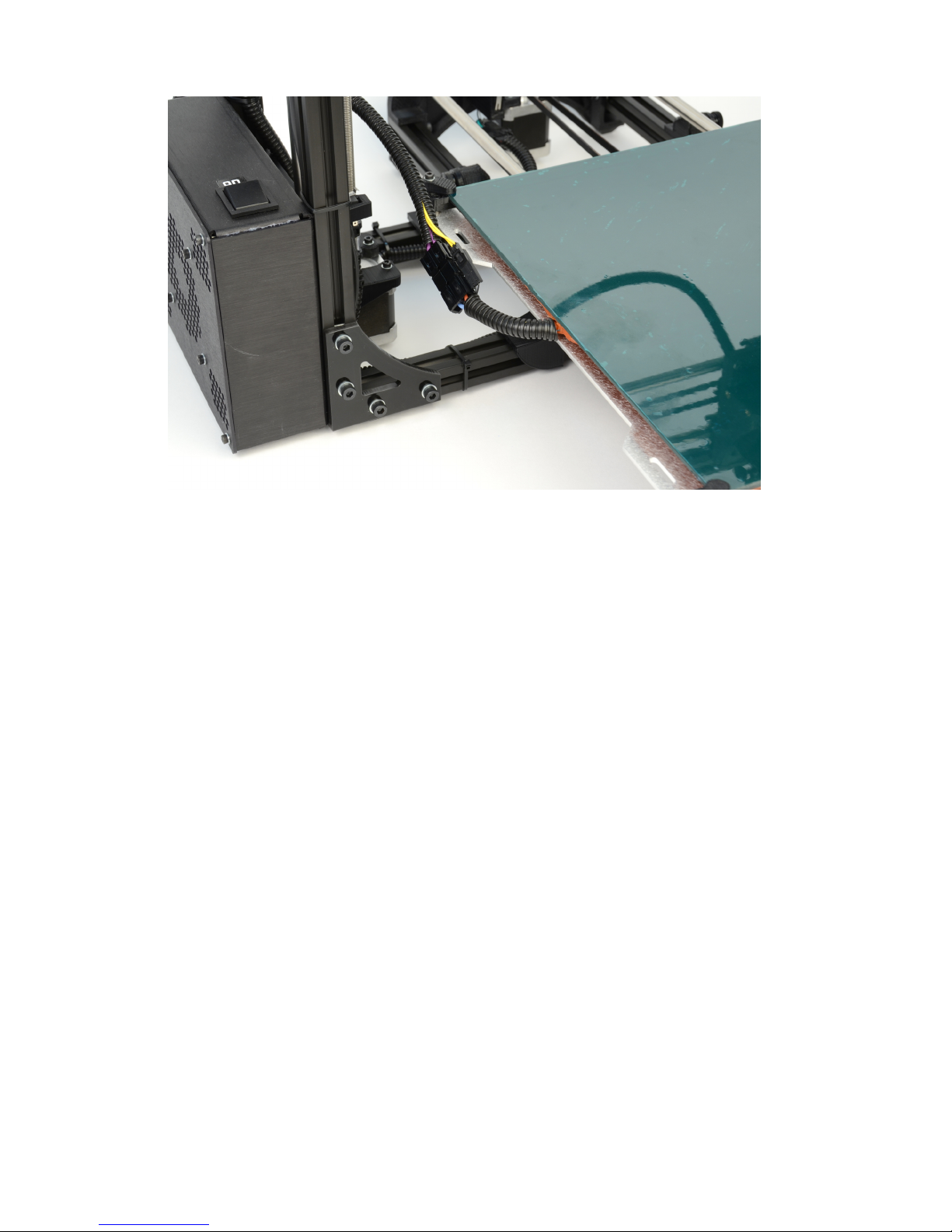
Setup Your Printer
Figure 1.8: Connect the two connectors on the left of the print bed
7.
Locate the other two small black zip ties that are included in the
documents bag (Fig. 1.9, page 23). Wrap the two zip ties through the
slot, located on the left rear of the aluminum bed plate, and around
the print bed wires (Fig. 1.10, page 23). Tighten the zip ties snug
so the wire cannot move freely. Cut off the excess end of the zip ties
with the needle nose pliers included in the tool bag.
22
Page 23
1.1. HARDWARE SETUP
Figure 1.9: Locate the two zip ties found in the bag with the manual
Figure 1.10: Tightly wrap the zip ties around the bed wires and through
the strain relief slot
23
Page 24
Setup Your Printer
8.
Before proceeding make sure that the four red shipping clamps on the
Z axis smooth rods have been removed.
9.
Move the X axis carriage to the center of the smooth rods. If you
have not already done so, remove the foam from between the X axis
carriage and the left hand X axis end. Locate and remove, with the
included 2.5mm hex driver, the tool head M3 screw in top center of
the X axis carriage (Fig. 1.11, page 24). Place the extruder tool head
mount onto the X axis carriage bottom first. The extruder mount
will slide into the bottom portion of the carriage and self center (Fig.
1.12, page 25).Make sure that the tool head mount is fully seated. Use
the 2.5mm driver and the previously removed M3 screw to secure the
extruder tool head onto the X axis carriage.
Figure 1.11: Remove the tool head screw
10.
Connect the stepper motor and the hot end to the existing wiring
harness located at the top of the X axis carriage. Connect the extruder
assemblies’ 4-pin connectors: match the orange/red wire connector
pair for the hot end and the mixed color wired connector pair for the
extruder motor (Fig. 1.13, page 25). Connect the matching pairs
together so they lock and click.
24
Page 25
1.1. HARDWARE SETUP
Figure 1.12: Mount the extruder tool head
Figure 1.13: Connect the two tool head connectors
25
Page 26

Setup Your Printer
11.
Now that the Y axis is mounted and the extruder tool head is installed
you should set your printer on a stable, flat, and level surface large
enough for extra space around the printer. Make sure your printer
work space is clear of anything that could obstruct the movement of
the printer. Move the Y axis to the back of the printer to ensure
unobstructed movement of that axis. Make sure there are no flammable
fabrics or liquids near the printer space. It is also best to not put your
printer near a drafty window or air conditioner vent.
12. Unwrap the power supply and USB cables.
MAKE SURE THE POWER SUPPLY IS COMPLETELY UNPLUGGED BEFORE MOVING ON TO THE NEXT STEP.
13.
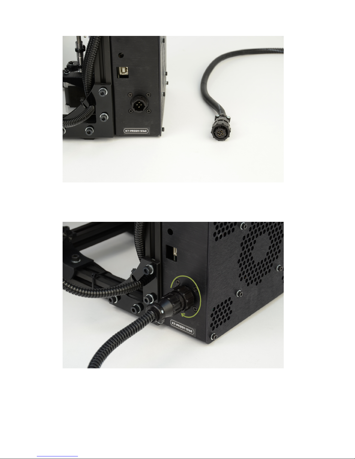
Locate the power supply and USB receptacles along the back of the
TAZ electronics enclosure (Fig. 1.14, page 27). Locate the power
supply and the included AC power cable (Fig. 1.15, page 27). Locate
the DC power cable plug on the power supply. Connect the DC locking
plug into the DC connector on the TAZ electronics enclosure (Fig.
1.16, page 28). The plug is keyed which may require rotating the plug
until the keys line up and the plug can be pushed in. Once you have
pushed in the plug turn the locking sleeve clockwise until it is tight
against the electronics enclosure (Fig. 1.17, page 28).
26
Page 27
1.1. HARDWARE SETUP
Figure 1.14: Power and USB receptacles
Figure 1.15: Power supply
27
Page 28
Setup Your Printer
Figure 1.16: 24V DC Power supply plug and receptacle
Figure 1.17: The power supply plug correctly plugged in
28
Page 29
1.1. HARDWARE SETUP
14.
Locate, on the right of the power supply, the red AC voltage switch. Depending on your location you will need to change the AC voltage switch
to 115V or 230V. North America is generally 115V and the majority
of other regions are 230V. You can find general voltage by country at
wikipedia.org/wiki/Mains electricity by country
. Make sure
that when plugging in the AC power cable it is directly plugged
into the wall and
not
into a power strip. The TAZ 3D printer can
potentially pull more current than the power strip will support and
may lead to undesirable performance.
15.
Plug in the USB cable, B plug (smaller square plug) side, into the
USB receptacle on the printer electronics. Plug the other end of the
USB cable, (larger), into your computer.
16.
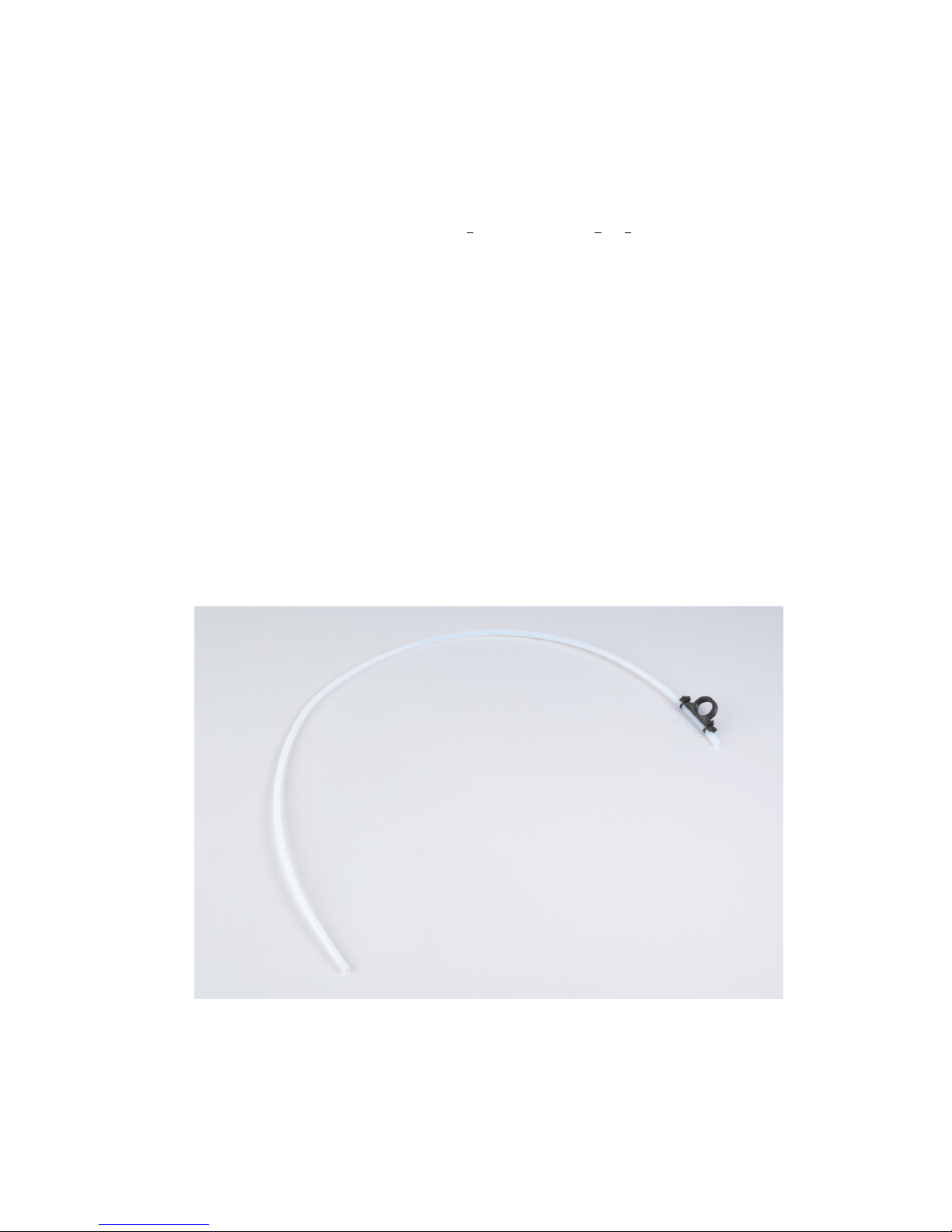
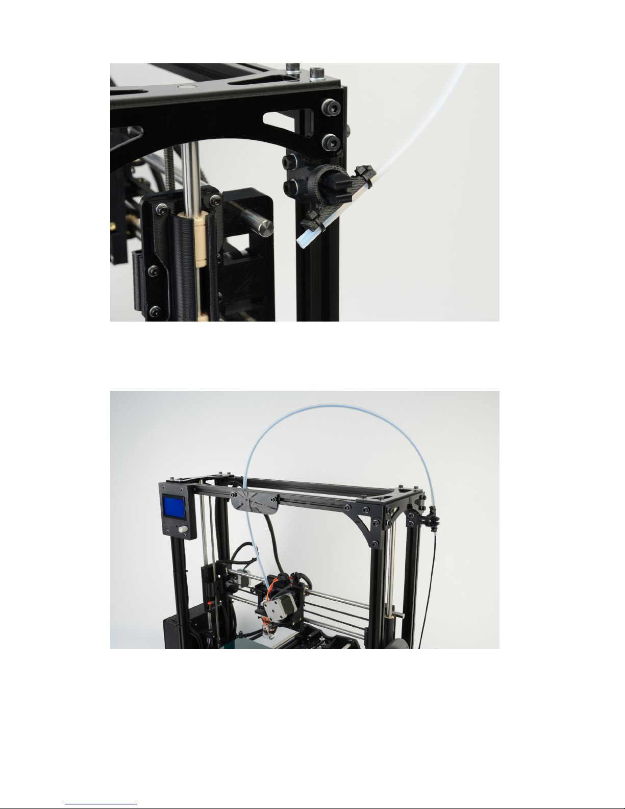
Locate the filament guide with attached PTFE tube (Fig. 1.18, page
29). The filament guide attaches to the filament guide mount which
can be found on the top right side of the printer frame (Fig. 1.19,
page 30). The filament guide easily pops on to the guide mount as
shown in figure 1.19 (pg. 30).
Figure 1.18: Filament Guide
29
Page 30
Setup Your Printer
Figure 1.19: Filament Guide Mount
Figure 1.20: Filament Guide Setting
30
Page 31
1.1. HARDWARE SETUP
Figure 1.21: Axes movement directions
Figure 1.22: End stop locations
31
Page 32

Setup Your Printer
1.2 ABS & Acetone Solution Prep
Please refer to section 8.3 (page 145) for instructions in preparing the
ABS/Acetone Glue for use when printing with ABS. As it will take
some time to dissolve the ABS into the acetone it may now be a good
time to make the solution. If you are printing with PLA, the ABS
and Acetone solution is not needed.
32
Page 33

Loading Filament
Page 34
Loading Filament
Before you start printing you will need to load a reel of filamant onto the
filament arm. The filament arm is meant to work with 1kg and 5lb plastic
filament reels but can be modified to work with other reel and spool types.
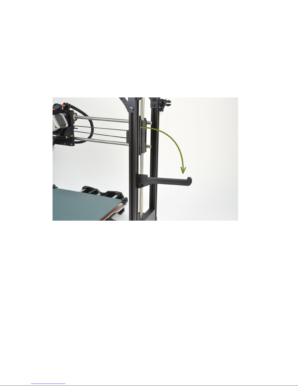
1.
On the front right hand side of the TAZ 3.0 3D printer you will find
the filament arm (fig. 2.1, page 34). Place the filament reel on the
filament arm with the filament feeding counter clockwise.
Figure 2.1: Filament reel arm
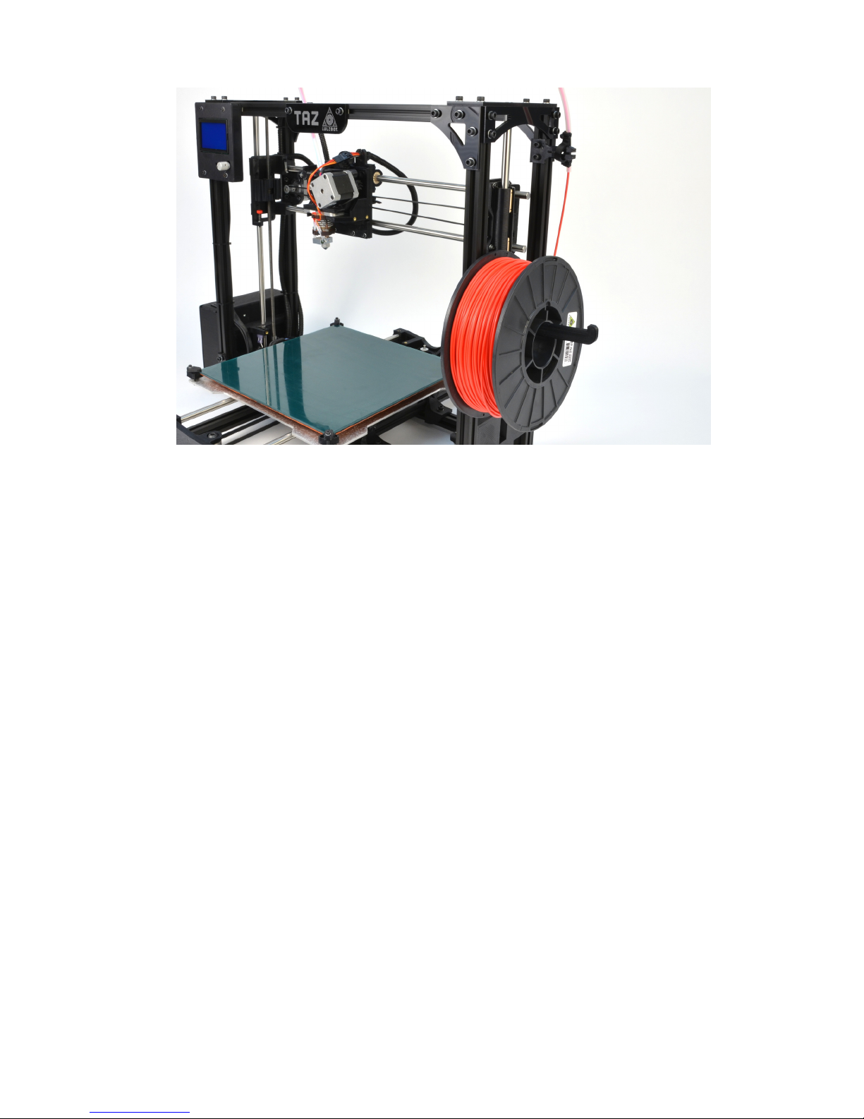
2.
Feed the end of the filament through the filament feed tube. The
Filament should now be threaded through the PTFE sleeve and exiting
near the extruder (fig. 2.2, page 35).
34
Page 35
LulzBotTMTAZ User Manual
Figure 2.2: Filament run through the guide
3. Your filament reel is now mounted and ready for the next steps.
4.
When changing filament, slide the opposite end of the filament through
one of the holes in hub of the filament spool. This will keep the filament
from unwinding from the spool.
35
Page 36

Page 37

3D Printer Software
Page 38

3D Printer Software
3.1 Software Overview
Aleph Objects, Inc., the maker of the LulzBot TAZ, completely supports
free/libre hardware and software. Along with the TAZ being a free/libre
hardware design, it has been tested to work with 100% free/libre software.
Our source code and design files are hosted on our development server found
at
http://devel.lulzbot.com
. To operate your desktop 3D printer you
will need to install a few software packages onto your PC. You will need
a 3D printer host, an
.STL
to
.gcode
generator, and optional CAD or 3D
modeling software.
All of the following free/libre software packages are available for
GNU/Linux, Windows, and Apple OS X. However, we highly recommend
using these programs on GNU/Linux.
The required software can be found in the Support/Downloads section
at
LulzBot.com/support/downloads
. You will also find instructions there
for installing each program onto your PC. You can also find downloads
specific to the TAZ 3D printer on the TAZ product page.
3.2 Installing Drivers
Linux and Mac OSX users will not need to install a driver to communicate with the TAZ 3D printer. Windows users will need to
install the following drivers. The drivers can be downloaded from
LulzBot.com/support/downloads
. A visual guide showing the driver
installation process can be found in our download section as well.
3.3 Printrun
Website: http://www.github.com/kliment/Printrun
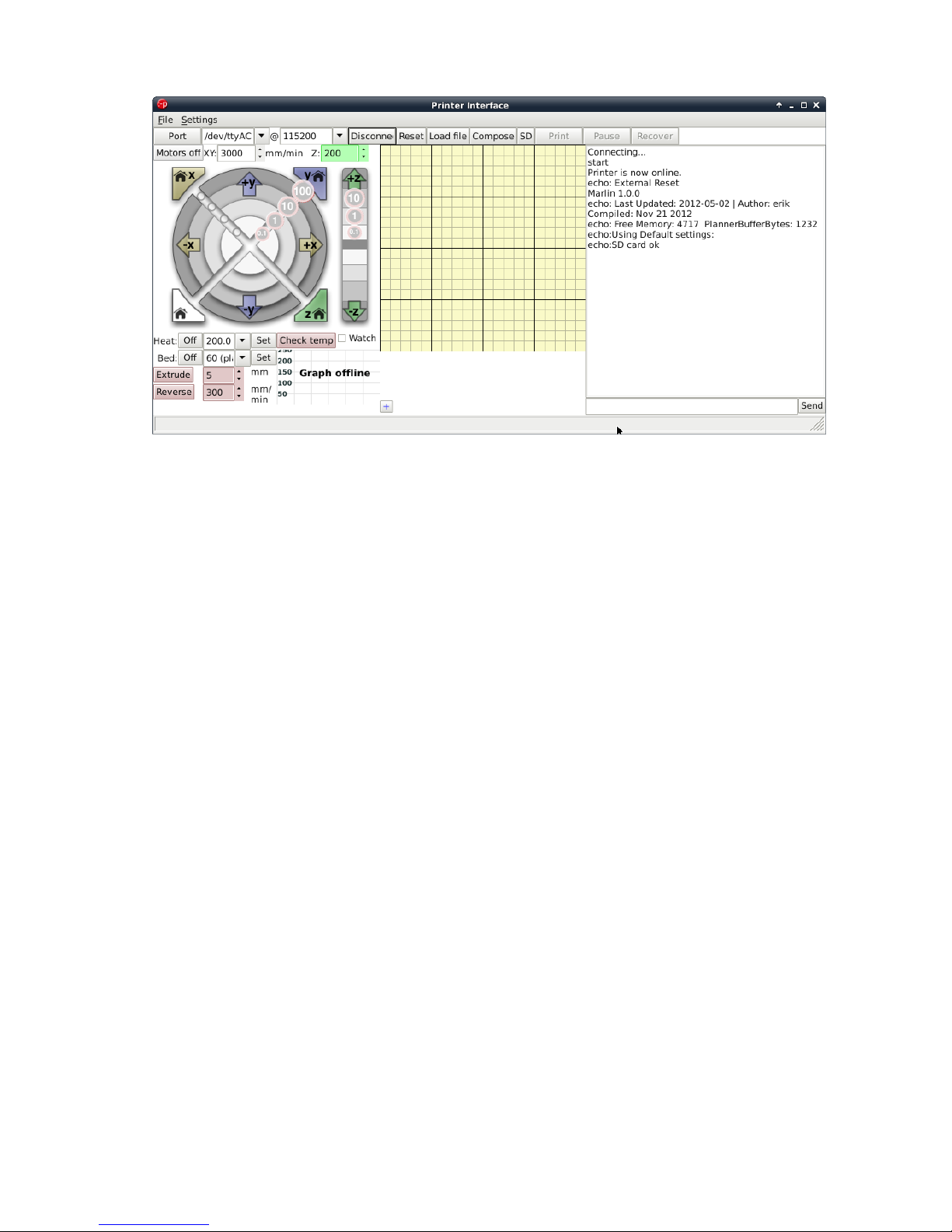
The host software, Printrun, is used to start up and control your 3D
printer (Fig. 3.2, page 41). The host controls include: setting the extruder
and print surface temperatures, manual control of each axis, and manual
extrusion. The host is also where you can push print files (
.gcode
) to
the 3D printer or load print files from the SD card for printing out model
designs.
38
Page 39
3.3. PRINTRUN
Figure 3.1: Printrun application for 3D printer control
Installing Printrun
Printrun contains several different applications that can be used to control the TAZ 3D printer. It can be installed on Windows, Mac OSX
and Linux based computers. We recommend using Pronterface, the
graphical user interface for printrun, when setting up or troubleshooting
the 3D printer.
Pronsole
allows printing from the command line, and
can be used for scripting and some automation.
Plater
allows you
to arrange and combine several STL files into one. More information
on the other programs within the Printrun package can be found at
https://github.com/kliment/Printrun
. Printrun can be downloaded
from
LulzBot.com/support/downloads
. Download the version for your
operating system and extract. You will need an archive manager to extract
the files. If you do not have one installed we recommend using 7-zip, which
can be downloaded for free at www.7-zip.org.
Windows Instructions
•
Once downloaded, extract the
dist
folder to a location of your
choice. You can rename the
dist
folder if you like. Double click
pronterface.exe to run Pronterface.
39
Page 40

3D Printer Software
Mac OSX Instructions
•
Once downloaded, extract the
dist
folder to a location of your choice.
Once extracted, double click the
pronterface-mac-Mar2012.app
file
to install.
Linux Instructions
Debian—Ubuntu
•
Once downloaded, extract the
dist
folder to a location of
your choice. You will need to ensure that the following
dependencies are met. They are listed in the README.md
file. You can use this command to install the dependencies:
sudo apt-get install python-serial python-wxgtk2.8
python-pyglet python-tornado python-setuptools
python-libxml2 python-gobject python-pip avahi-daemon
libavahi-compat-libdnssd1
followed by:
pip install -r
requirements.txt
Open the
Printrun-source
folder in a terminal
and enter the following command:
sudo python setup.py
install
. Run Printrun by issuing the following command:
python
pronterface.py
Fedora
•
Use this command to install Printrun from the official sources:
sudo
yum install printrun
Archlinux
• Use this command to install Printun from AUR: yaourt printrun
40
Page 41
3.4. USING PRINTRUN
3.4 Using Printrun
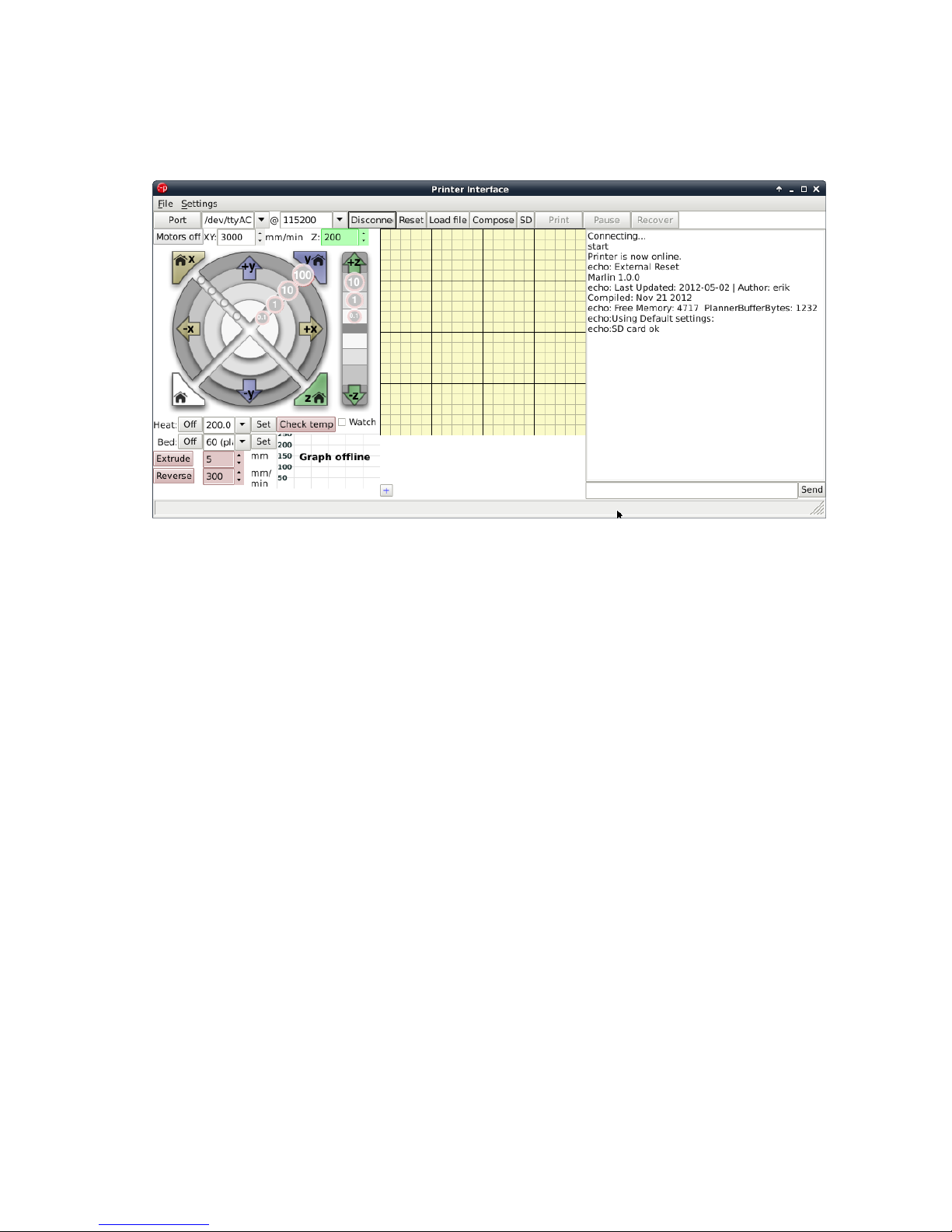
Figure 3.2: Printrun
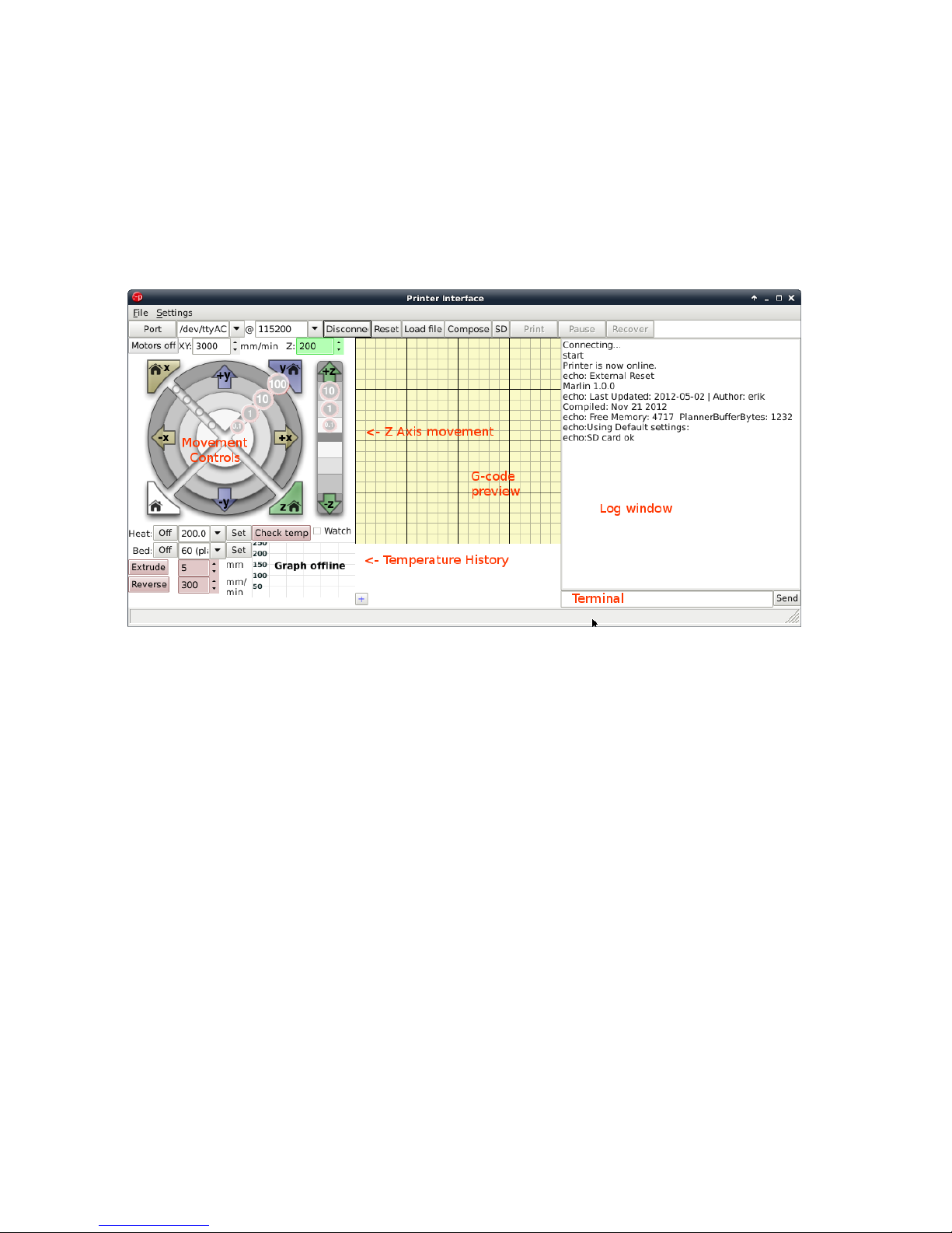
Printrun is used to control the printer from a computer. It is divided into 4
main parts: The buttons over the top are used to connect to the printer,
load files and start & stop prints.
The movement controls are on the left hand side, with the G-code
preview window in the center and the Log window and Terminal command
entry box on the right hand side (Fig. 3.2, page 41).
Connecting to the TAZ 3D Printer
To start up the printer, first you will need to connect to the printer with
Printrun. Make sure you have connected the USB cable from your PC
to the printer before launching Printrun. If not, close Printrun, connect
the USB cable, and relaunch Printrun. To connect to the printer, select
the correct port by using the drop down arrow and selecting the active
port, generally
/dev/ttyACM0
). On other operating systems the port may
be named such as
COM1
or
tty.usbserial-USB-ID
. The
Port
button will
refresh the Port listing. Once selected choose the default
115200
buad rate
and press
Connect
. Pronterface will open a connection to the printer and
display firmware information in the Log window.
41
Page 42
3D Printer Software
In the text output window you will see multiple return lines. If you see
Printer is now online
you have successfully connected to the printer.
The printer control buttons on the left will also darken and become click-
able after connecting. If nothing is displayed in the Log window verify you
have the correct port and connection speed selected. When you need to
disconnect the printer simply press the Disconnect button.
Figure 3.3: Printrun Functions
42
Page 43
3.4. USING PRINTRUN
Movement
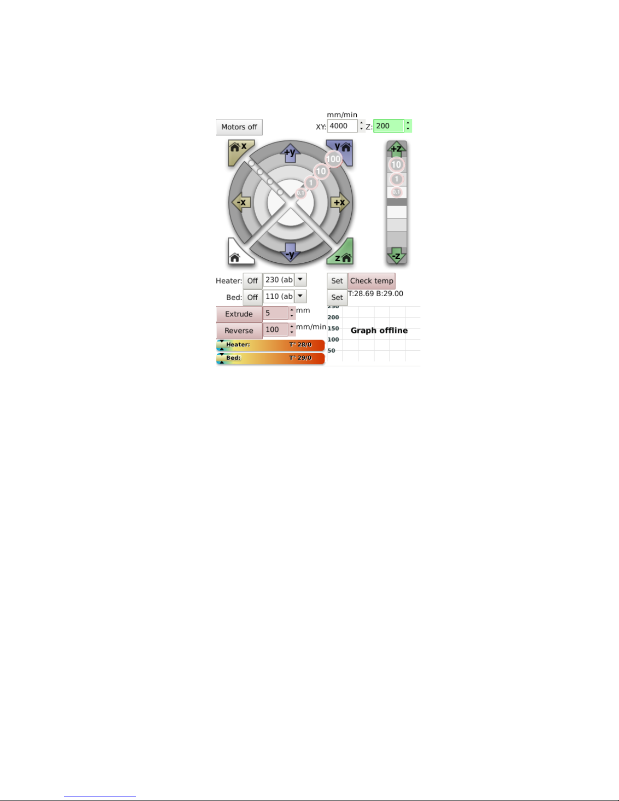
Figure 3.4: Movement Controls
Motors off
The TAZ 3D printer can be moved on all three axes independently. If you
would like to do so by hand, use the
Motors off
button to unlock all the
stepper motors. Once unlocked they can be moved by hand. Keep in mind
that there is no positional feedback, so if you move an axis you will need to
re-home in order to re-establish the hot end’s position.
mm/min XY:/ Z:
These settings control the manual jog speeds when driven with Pronterface.
Use caution when changing these figures. Moving the axes too fast can cause
the printer to lose steps. If that occurs with the Z axis, it can potentially
cause the Z axis to become out of square.
43
Page 44

3D Printer Software
Homing
Caution: when homing, the axis will continue to move in the negative
direction until the end stop switch is activated. If the printer is ever
transported make sure the end stop switches are clear before resuming
printing. If an axis has missed an end stop and is continuing to try to
move in the negative direction, immediately turn the power switch to the
off position.
Each axes can be homed either individually or together. Press the
Home
X
button to move the X axis to the left until it activates the end stop. Once
the X axis end stop is activated, the X axis carriage will ’bounce’- it will
move over and move back to the home position more slowly. Press the
Home
Y
button to home the Y axis. The Y axis platform will move away from you
towards the rear of the printer. The Z home button functions the same, but
the Z trigger can be adjusted manually on the printer. DO NOT press the
Home Z
button to home the Z axis or the
Home All button
at this time.
In a later step you will need to set the Z end stop trigger before homing Z.
X/Y/Z Axes Movement Controls
Prior to moving the X, Y or Z axis, make sure that you home each axis.
The X, Y and Z axes can be moved utilizing the circular movement controls.
Each axis can be moved in either fine moves or large moves, ranging from
0.1mm to 100mm. For example, to move the
Y Axis
towards you, move
your mouse to the
+y
section until both the
+y
and the
100
are highlighted
then select that ring section. To move the
Y axis
away from you, move
your mouse to the
-y
section until both the
-y
and the
100
are highlighted
then select that ring section. The X axis can be moved in a similar fashion.
DO NOT press the
Home Z
button to home the Z axis or the
Home All
button
at this time. The Z axis movement control operates similarly, but
the movement scale is different. The Z axis will move in 0.1mm, 1mm and
10mm increments. The top half of the movement bar will move the Z axis
up, by the selected units, while the lower half will move the Z axis down,
by the desired units.
44
Page 45

3.5. CAD AND 3D MODELING SOFTWARE
3.5 CAD and 3D Modeling Software
Currently LulzBot is not distributing a CAD or 3D modeling software
package. However, there are multiple free/libre software packages available.
Other common non-free CAD and 3D modeling software are also capable of
exporting the required .STL files.
On some CAD and 3D modeling software you will need to select
millimeters as the output unit. If possible it is best to build your 3D
design in metric units rather than imperial units. Slic3r requires .STL files
sized in millimeters. If an .STL with inches as units is loaded into the
Slic3r, the model will be scaled much smaller than expected. You can scale
the model by 2540% to compensate. The software listed below outputs
millimeters as the unit by default.
FreeCAD
Website: http://free-cad.sourceforge.net
Although still in development, FreeCAD is a great free/libre CAD
application. Containing a full GUI for building CAD models, FreeCAD is
capable of creating simple to complex designs. STL files can also easily be
exported for use with 3D printing. FreeCAD is available for GNU/Linux,
Windows, and Mac. The latest development version is recommended.
OpenSCAD
Website: http://openscad.org
OpenSCAD is another free/libre CAD software; however, different than
FreeCAD, it is script based. Rather than using a GUI to generate CAD
designs, OpenSCAD CAD designs are created using script based renderings.
Users with programming experience would find this very useful. Also,
OpenSCAD uses a simple script language that is easy to learn for users
with little or no programming experience.
Blender
Website: http://blender.org
45
Page 46

3D Printer Software
The most widely used Free/Libre 3D modeling software, Blender is well
documented with tutorials available on the Blender.org website. Numerous
video tutorials can be also found online.
Shapesmith
Website: http://shapesmith.net
Shapesmith is a web based 3D modeling software. This means there is
no required software to get started designing models. Shapesmith is also a
great choice for anyone just starting out in CAD/ 3D modeling.
46
Page 47

Your First 3D Print
Page 48
Your First 3D Print
4.1 Bed Leveling
Make sure you take the time to go through the following procedure to
help ensure that your prints are consistent and trouble free. Make sure to
first read the instructions for using the Printrun software. Connect to the
printer as described in the Printrun software section. Once
Pronterface
is
connected to the printer use the homing buttons to home the X and Y axis.
Do not use the
Home Z button
until after the
Z axis End stop
has been
adjusted. Make sure that the red shipping clamps on the Z axis smooth
rods have been removed before continuing.
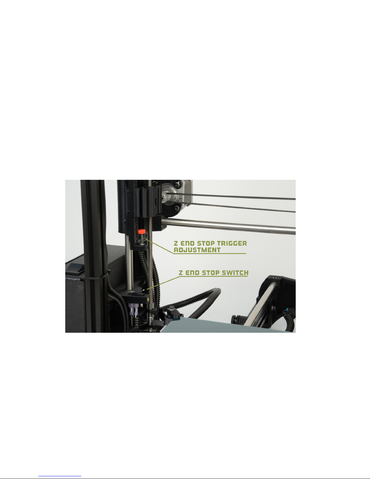
Rough Adjustment of the Z Axis End Stop Trigger
Figure 4.1: Z end stop trigger
Before using the
home Z
button or the
home all
button you will need to
adjust the
Z axis endstop trigger
. The red end stop trigger is on the far
left of the printer, mounted on the X-axis motor mount. Once connected to
the TAZ 3D printer in Pronterface, Rotate the
Z axis end stop trigger
clockwise to lower the bottom of the screw closer to the Z axis end stop.
48
Page 49

4.1. BED LEVELING
Once lowered by approximately 1cm, press the
Home Z button
to home the
Z axis. The hot end will approach the heated bed and should stop around a
centimeter above the surface of the heated bed. While the Z axis is moving
down pay attention to the Z axis movement and sound. The Z axis stepper
motors should be moving in unison. If you notice a grinding sound, stop,
turn the printer off and before proceeding, make sure that the Z axis looks
level in relation to the body of the TAZ 3D printer. Manually rotate one
of the Z axis linear threaded rods by hand if needed to visually level the Z
axis.
Raising the Z Axis
Use the
+Z 10 button
to move the Z axis up in
10mm
increments. Com-
mands sent in Pronterface will stack, so multiple movement button presses
can potentially be harmful and cannot be stopped without powering down
the 3D printer. Keep an eye on the nozzle for the hot end. Raise the Z axis
until the hot end nozzle is approximately 40-50mm away from the print bed.
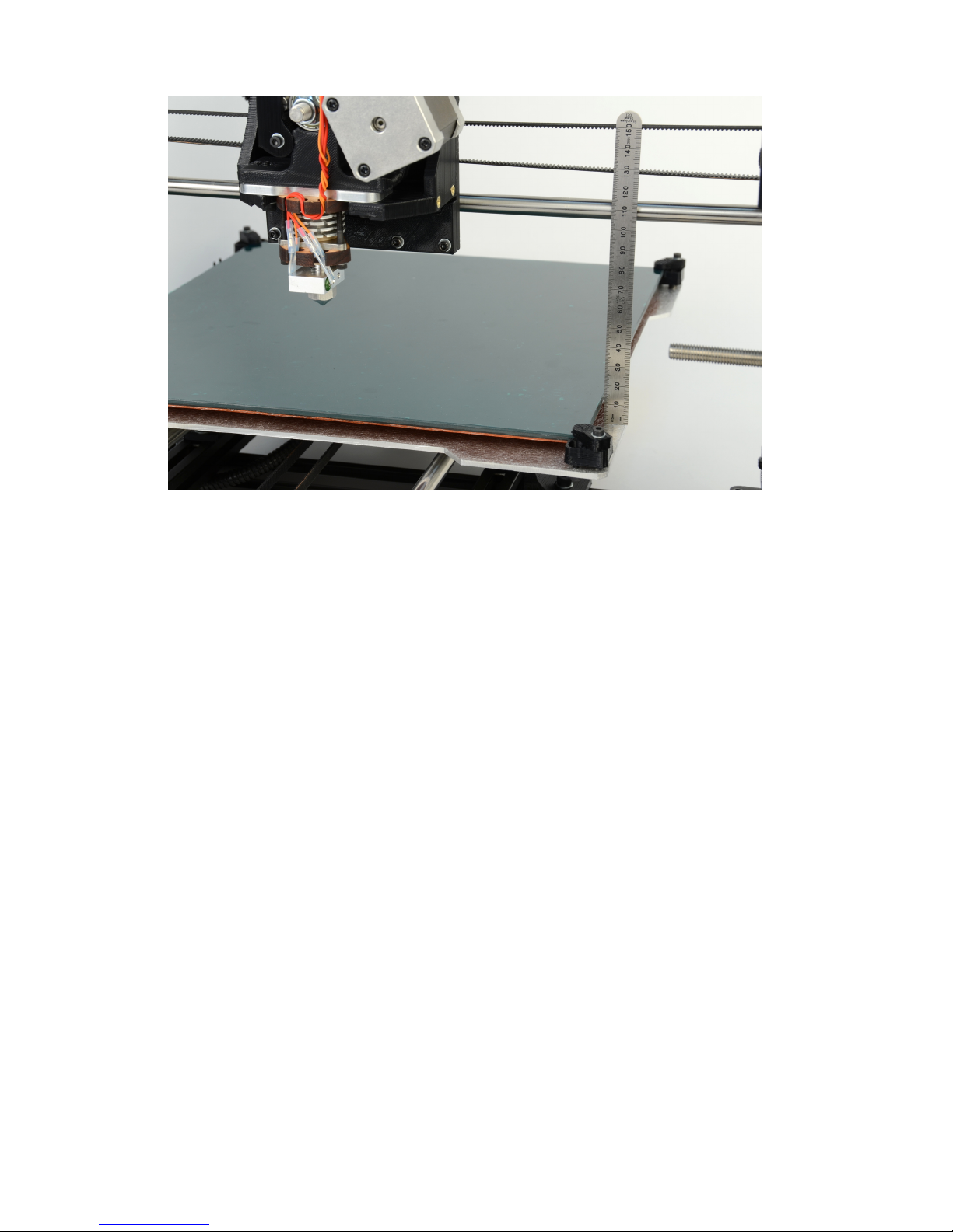
Verify Z Axis Leveling
With the Z axis above the bed, use the included
150mm ruler
to measure
the distance from the bottom of the
X axis
smooth rod and the top surface
of the Y axis aluminum bed plate on the left side (Fig. 4.2, page 50).
49
Page 50
Your First 3D Print
Figure 4.2: Verifying the X and Y axis are square
Compare the distance measurement from the left side to the measurement
on the right side. The distance measurement should be the same. If not,
in Pronterface use the
Motors off
button to turn off the stepper motors
on the TAZ 3D printer. Manually, by hand, turn the threaded rod on one
side of the printer to raise or lower that side to match the measurement on
the other side. If the Z axis has been adjusted measure again to confirm
that the left and right side of the Z axis are level in relation to the Y axis
aluminum plate.
Fine Adjustment of the Z Axis End Stop
Now that the Z axis is checked for level a finer adjustment of the Z axis end
stop trigger can be set. Adjust the
Z axis end stop trigger
by rotating
the screw counter-clockwise to raise the tip of the screw. Raise the screw
by roughly the same amount of the distance between the nozzle tip and the
print surface. Press the
Home Z
button to home the Z axis. The tip of the
nozzle should now be very close to the surface of the bed.
50
Page 51

4.1. BED LEVELING
Leveling the Print Bed
Slide a thin piece of paper underneath the nozzle in the front left corner
of the bed. Adjust the Z axis end stop and home the Z axis until the tip
of the nozzle applies a firm pressure on the paper. Test by attempting to
slide the paper out from under the nozzle. A gentle resistance should be
felt, in addition to a visible impression on the paper. If the paper tears, the
nozzle is too close. Adjust the Z axis homing height by adjusting the Z axis
endstop, turning clockwise in 180 degree increments to increase the Z axis
homing and turning counter-clockwise to decrease the Z axis homing height.
Once adjusted, press the +Z 10 button to raise the Z axis.
Move the hot end nozzle tip over to the far side of the X axis by using
the
+X 100 button
. As the X axis carriage approaches the end of the X
axis use the
+X 10 button
and finally the
+X 1 button
. Once the tip of
the nozzle is near the front right corner of the bed slide the same piece
of paper under the nozzle and home the Z axis. Adjust the corner’s bed
leveling screws so that the tension felt when moving the paper under the
nozzle matches the tension felt previously. To raise or lower the front right
corner of the bed, adjust the screw with the spring only. Do not adjust the
middle screw. Turn the screw clockwise to lower the bed, thereby decreasing
the tension felt when moving the paper. Turn the screw counter-clockwise
to increase the tension felt when moving the piece of paper from under
the nozzle. Adjust the front right corner of the bed until the amount of
tension felt when moving the piece of paper under the nozzle feels the same
as the tension felt when doing the same thing on the front left corner. Once
adjusted, press the +Z 10 button to raise the Z axis.
Repeat the same process using the
+Y button
to move the heated bed
to place the nozzle on the rear right corner of the bed. Adjust the height of
the bed using the same procedure as outlined above. Once adjusted, press
the +Z 10 button to raise the Z axis. Finally, move the X axis carriage over
to the rear left corner of the bed and perform the same leveling procedure
to adjust the last corner.
The bed should now be almost perfectly level. We will check this in a
later section. Use the controls in Pronterface to raise the Z axis up 20mm,
and move the X axis carriage over to the center of the X axis.
51
Page 52

Your First 3D Print
4.2 Set Temperature
The TAZ 3D printer ships with a small length of ABS filament from our
testing prior to shipping. The filament will need to be removed before
proceeding. In order to do so set the hot end to 230C. Make sure that the
Monitor Printer
(Found in the upper middle portion of the Pronterface
window) check box is selected. Once the hot end has reached 230C, gently
squeeze both the idler screws and the plastic clip together and pull upwards
to release the idler. Rotate the idler counter clockwise, exposing the filament
and the filament drive (hobbed bolt). Remove the filament by hand by
gently pulling it out. Allow more time for the filament to soften if the
filament cannot be removed easily.
Set the hot end and print surface for ABS or PLA plastic and turn both
on. The temperature settings for ABS should be set at
230◦C
for the hot end
and
85◦C
for print surface; for PLA they should be set at
185◦C
for the hot
end and
55◦C
for print surface. These temperatures work well for filament
sourced from LulzBot, however you may need to adjust the temperature a
degree or two depending on the filament source, color and type. Click the
Motors Off button.
4.3 Load Filament
Once the hot end is heated to the correct temperature you will now need to
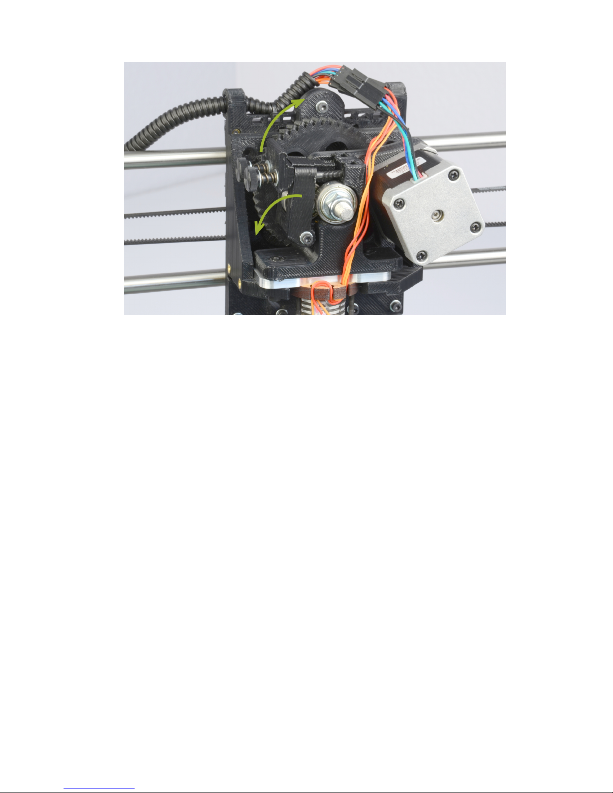
load the plastic filament into the extruder. Gently squeeze both the idler
screws and the plastic clip together and pull upwards to release the idler
(Fig. 4.3, page 53). The idler screws can be loosened if necessary. The
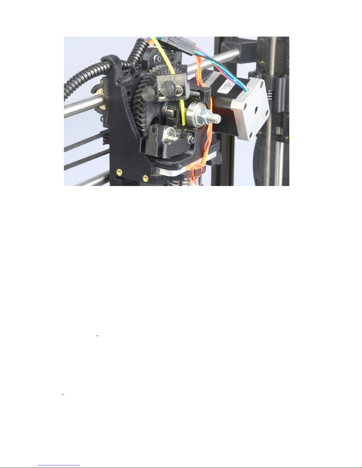
idler can be rotated downwards allowing access to the hobbed bolt and
filament feed hole(Fig. 4.4, page 54). If the extruder has a small section
of filament already loaded, you will need to remove the filament once the
extruder idler has been opened, by gently pulling out the filament by hand
once the hot end has reached extrusion temperature. From the previously
installed filament reel, feed the end of the plastic filament into the filament
feed hole (Fig. 4.4, page 54). Now you can push the filament through the
extruder by slowly pushing the filament down into the hot end.
Once the filament extrudes a small amount out of the nozzle by manually
pushing the filament into the extruder body raise the idler and slide the
two idler bolts and plate back into place. Tighten the two idler bolts if
52
Page 53
4.4. HOME PRINTER
Figure 4.3: Extruder idler release
you previously loosened them. Tighten the two screws until they are finger
tight, then tighten them slightly more, until the top of the thumbscrews
are about 10mm away from the plastic clip. In Pronterface, in the lower
left hand corner of the screen there are two text entry boxes next to the
”Extrude” and ”Reverse” buttons. In the top text entry box (length in mm)
change the 5 to 40. In the lower box (Speed in mm/min) change the 300 to
250. Now use the
Extrude
button in Pronterface to test that the extruder
is working properly. You may need to extrude 40-60mm of filament to fully
prime the hot end. Slowly tighten the two extruder thumbscrews while
extruding until you achieve reliable, repeatable extrusion. If the extrusion
stalls you may need to open the extruder and trim off any filament with a
chewed out section.
4.4 Home Printer
Use the home buttons to home the X axis and then the Y axis. Next home
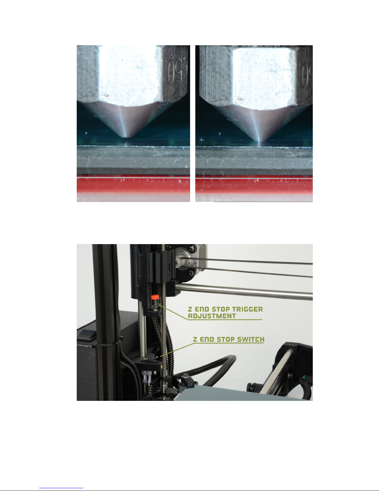
the Z axis. When the Z axis is at home the nozzle tip should be right above
the glass (Fig. 4.5, page 55). The image to the left, in figure 4.5, is the
53
Page 54
Your First 3D Print
Figure 4.4: Extruder filament slot
correct nozzle height. The nozzle should not be pushing down on the print
surface. To lower or raise the Z home height adjust the Z end stop trigger.
The red end stop trigger is on the far left of the printer mounted on the
X-axis motor mount. (Fig. 4.6, page 55). The red end stop trigger can be
lowered by turning clockwise and raised by turning counter-clockwise. Once
you have homed the axes and the hot end and bed have reached the correct
temperature it is time to print!
4.5 Z Print Height
Load the
bed level.gcode
file. This file can be found in the calibration
directory on the SD card included with your TAZ 3D printer or at:
http://www.LulzBot.com/support/downloads
. Place your mouse cursor
over the entry
Bed Level Check
, right click and select
Save as
Once you
have downloaded the file to your computer, press the
Load file
button
in Pronterface. Navigate through the file browser to the downloaded
bed level.gcode file, highlight the file and select the Open button.
54
Page 55
4.5. Z PRINT HEIGHT
Figure 4.5: Nozzle height
Figure 4.6: Z end stop trigger
55
Page 56
Your First 3D Print
The .gcode file should appear in the Pronterface G-Code viewer. Press
the
Print
button to begin the print. When the print starts make sure the
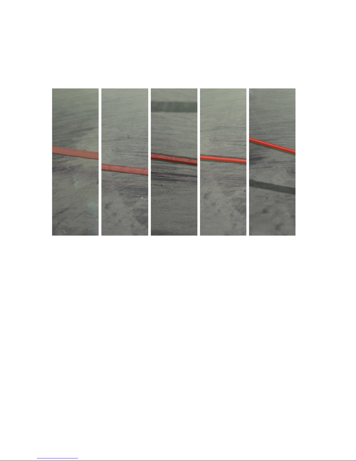
first layer is not printing too close or too far from the print bed. Note Figure
4.7, page 56, as an example of a good first layer adhesion. From left to right:
Figure 4.7: First layer adhesion
very low, low, perfect, high, very high. If the first layer is too high or low
you can pause the print by pressing the
Pause
button. Adjust the Z end
stop trigger. After making adjustments remove any printed material off the
bed and home the axes and press
Restart
to restart the print. Measure
the extrusion width, ideally the width would be the same in all areas of the
bed. You would raise/lower a corner to minimize/increase the extrusion
width to match the others. Once they are all consistent, the bed is level.
4.6 Your First Octopus!
Load the
octopus.gcode
file. This file can be found at:
http://www.download.com/TAZ/3.0/novelties/
. Load the file in
Pronterface, bring the hot end
(230C ABS/185C PLA)
and the heated bed
56
Page 57

4.7. REMOVE PART
(85C ABS/60C PLA)
up to printing temperature. Once the printer is at the
appropriate temperature, press the Print button to begin the print.
4.7 Remove Part
After the part is finished printing, the heated bed will automatically cool
down to room temperature. If you are printing PLA you will need to turn
the heated bed off. Once the bed cools you can you pop the finished part
off of the printed surface. To remove the printed part, use the clam knife
included in your printer kit. Leather gloves are suggested to protect your
hands from the clam knife blade. It is also safe practice to not place your
hand in the direction you are pushing the clam knife. Using the side of
the clam knife blade pry up one side of the printed part. If your part is
large you may need to pry at multiple points to pop the part off of the print
surface. When removing parts take caution to not damage the PET film. If
the film is cut or ripped it will peel from the glass and need to be replaced.
Make sure to reset the heated bed to the correct temperature and allow it
to heat up to the needed temperature before starting the next print.
57
Page 58

Page 59

Slic3r
Page 60

Slic3r
5.1 Introduction
Overview
Slic3r is a tool which translates digital 3D models into instructions that are
understood by a 3D printer. It slices the model into horizontal layers and
generates suitable paths to fill them.
Slic3r is already bundled with the many of the most well-known host
software packages: Pronterface, Repetier-Host, ReplicatorG, and can be
used as a standalone program.
This manual will provide guidance on how to install, configure and utilize
Slic3r in order to produce excellent prints.
This portion of the manual is derived from the complete Slic3r manual.
It has been customized for TAZ users. The original unabridged version can
be found at manual.slic3r.org.
Goals & Philosophy
Slic3r is an original project started in 2011 by Alessandro Ranellucci (aka.
Sound), who used his considerable knowledge of the Perl language to create
a fast and easy to use application. Readability and maintainability of the
code are among the design goals.
The program is under constant refinement, from Alessandro and the
other contributors to the project, with new features and bug fixes being
released on a regular basis.
Donating
Slic3r started as a one-man job, developed solely by Alessandro in his
spare time, and as a freelance developer this has a direct cost for him. By
generously releasing Slic3r to the public as open source software, under the
GPL license, he has enabled many to benefit from his work.
The opportunity to say thank you via a donation exists. More details
can be found at: http://slic3r.org/donations.
60
Page 61

5.2. GETTING SLIC3R
5.2 Getting Slic3r
Slic3r is Free Software, and is licensed under the GNU Affero General Public
License, version 3.
Downloading
From LulzBot
The Slic3r version that has been tested for the TAZ printer
can be downloaded from the LulzBot.com downloads page:
https://www.lulzbot.com/support/downloads.
Pre-compiled packages are available for Windows, Mac OS X and Linux.
Windows and Linux users can choose between 32 and 64 bit versions to
match their system.
Slic3r
Slic3r can be downloaded directly from: http://slic3r.org/download.
Pre-compiled packages are available for Windows, Mac OS X and Linux.
Windows and Linux users can choose between 32 and 64 bit versions to
match their system.
Manual
The latest version of full Slic3r manual, with LATEX source code, can be
found at: https://github.com/alexrj/Slic3r-Manual
Source
The source code is available via GitHub:
https://github.com/alexrj/Slic3r
. For more details on building
from source see §5.2 below.
Installing
Linux
Extract the archive to a folder of your choosing. Either:
61
Page 62

Slic3r
•
Start Slic3r directly by running the Slic3r executable, found in the
bin directory, or
•
Install Slic3r by running the do-install executable, also found in the
bin folder.
The archive file may then be deleted.
Windows
Unzip the downloaded zip file to a folder of your choosing, there is no
installer script. The resulting folder contains two executables:
• slic3r.exe - starts the GUI version.
• slic3r-console.exe - can be used from the command line.
The zip file may then be deleted.
Mac OS X
Double-click the downloaded dmg file, an instance of Finder should open
together with an icon of the Slic3r program. Navigate to the Applications
directory and drag and drop the Slic3r icon into it. The dmg file may then
be deleted.
Building from source
For those wishing to live on the cutting edge, Slic3r can be compiled from the
latest source files found on GitHub
https://github.com/alexrj/Slic3r
.
Up-to-date instructions for compiling and running from source can be
found on the Slic3r wiki.
5.3 First Print
Calibration
Before even attempting the first print it is vital that the printer is correctly
calibrated. Skipping or rushing this step will result in frustration and failed
prints later, so it is important to take the time to make sure the machine is
62
Page 63

5.3. FIRST PRINT
correctly set up. Be sure to complete the Setup and First Print section of
this manual before moving forward with Slic3r.
If you are just beginning with 3D printing or Slic3r, LulzBot recommends
starting with our pre-set Slic3r profiles. You can find the TAZ Slic3r profiles
at
https://www.lulzbot.com/support/downloads
. For information on
loading and export Slic3r profiles please see page 116. Note that the pre-set
profiles will only work correctly when Slic3r is in Expert mode.
The pre-set profiles will give you Slic3r settings that will work great on
most designs. The Slic3r manual can be used as a reference in building
knowledge of Slic3r settings while using the pre-set profiles. Once you have
a number of prints completed you can use the Slic3r manual as a reference
to make small adjustments to the pre-set profiles or begin creating your
own profiles.
63
Page 64
Slic3r
Configuration Wizard
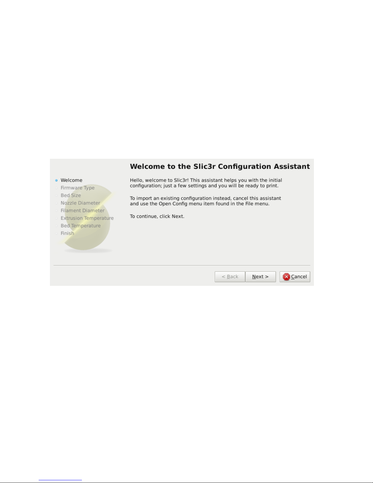
Slic3r has two features to aid newcomers: the configuration wizard, and
simple mode.
Sometimes it is nice to have a helping hand when starting out with new
software. The configuration wizard asks a series of questions and creates a
configuration for Slic3r to start with.
When using the pre-set TAZ Slic3r profiles you do not need to
complete the Configuration Wizard.
The Configuration Wizard can
be later accessed from the top menu once you are ready to start creating
your own Slic3r profiles.
Figure 5.1: Configuration Wizard: Welcome Screen
64
Page 65
5.3. FIRST PRINT
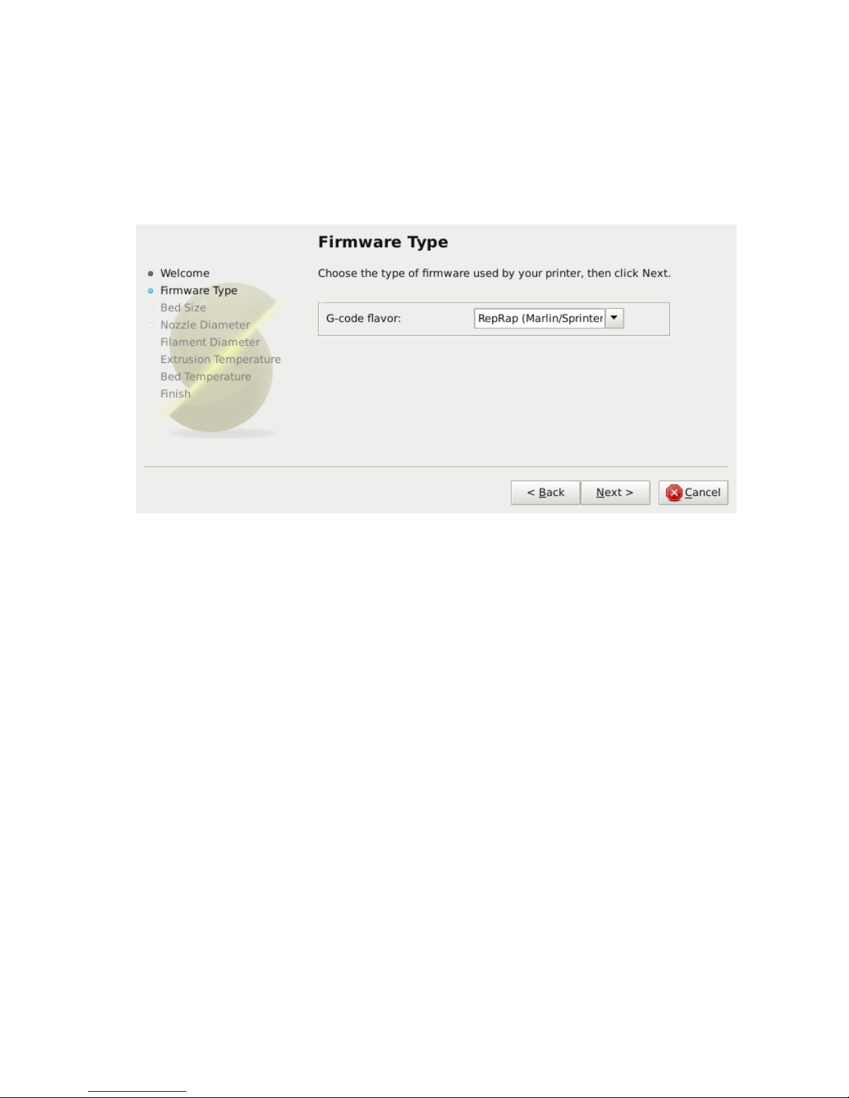
1. Firmware Type
The gcode produced by Slic3r is tailored to particular types of firmware.
The first step prompts for the firmware that the printer uses. For the TAZ
printer select RepRap (Marlin/Sprinter)
Figure 5.2: Configuration Wizard: Firmware Type
65
Page 66
Slic3r
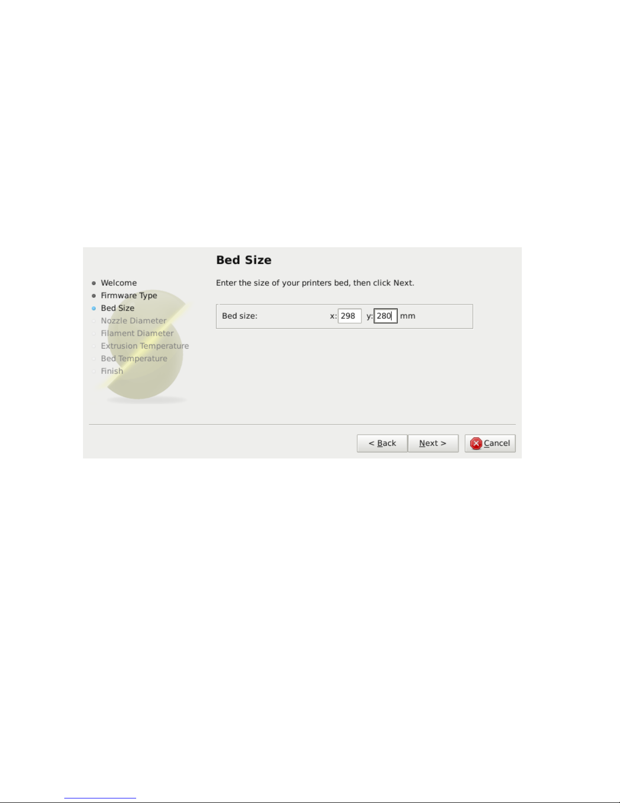
2. Bed Size
This setting defines the maximum distance the extruder may travel along
the X and Y axis. The dimension for the TAZ print surface are X: 298 and
Y: 280.
Be sure to measure from the lower left corner where the extruder nozzle
rests when are the home position to the maximum distance the nozzle can
travel in each direction. Take into account that the X carriage may touch
the frame before the nozzle reaches it’s full distance, this will depend on
the printer make and model.
Figure 5.3: Configuration Wizard: Bed Size
66
Page 67
5.3. FIRST PRINT
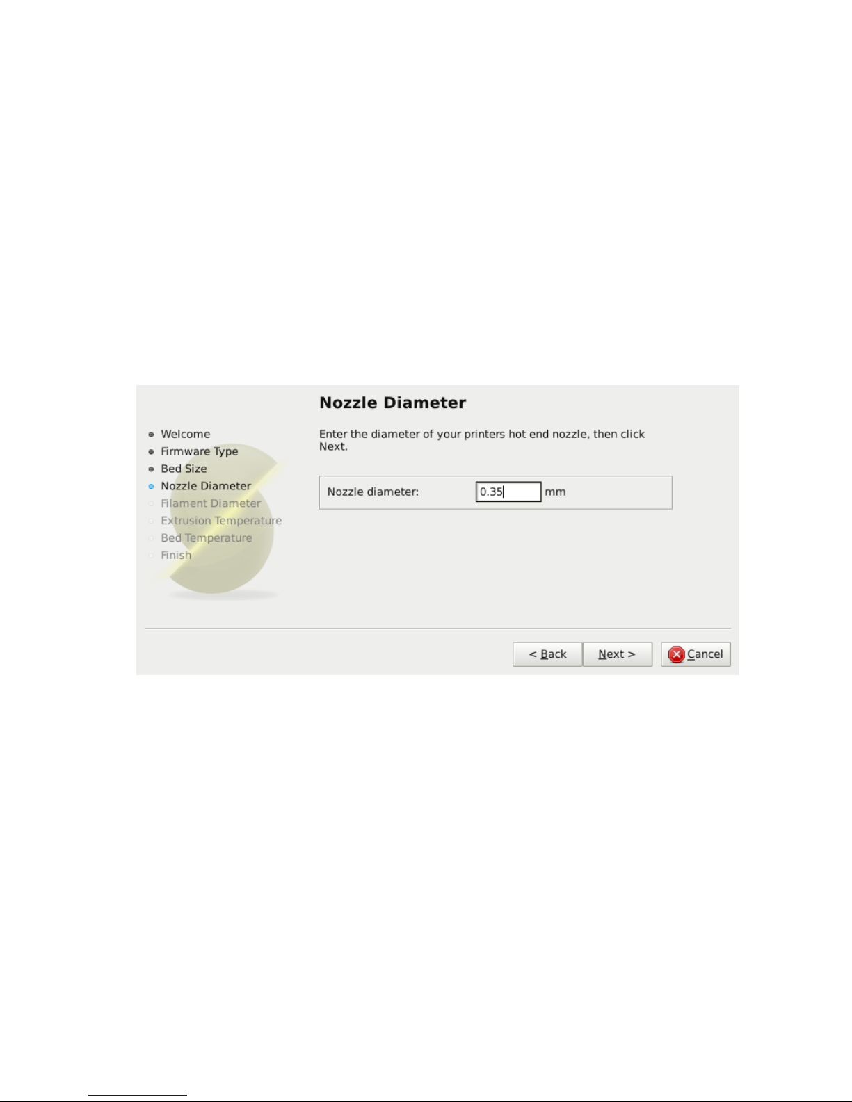
3. Nozzle Diameter
The diameter of the hot-end nozzle is usually clearly displayed either in
the description of the hot-end, or in the associated documentation, when
the hot-end is purchased. The default nozzle size on the TAZ hot end is
0.35mm.
If the nozzle was home-made, or came from a source without a diameter
given, then carefully measure the aperture as accurately as possible. One
way of determining nozzle size is to very slowly (1mm/s) extrude some
filament into free air and measure the thickness of the resulting extrusion1.
This has the benefit of taking die swell into account, and consequently may
be a useful thing to do even if the diameter is known.
Figure 5.4: Configuration Wizard: Nozzle Diameter
1
http://forums.reprap.org/read.php?1,113374,113953
67
Page 68
Slic3r
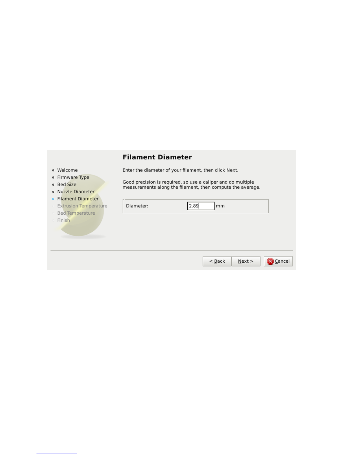
4. Filament Diameter
For Slic3r to produce accurate results it must know as accurately as possible
how much material is pushed through the extruder. Therefore it is vital to
give it as precise a value as possible for the filament diameter.
Although the filament used in FDM printers is sold as being either
3mm or 1.75mm this is only a general guide. The diameter can vary
between manufacturers and even between batches. Therefore it is highly
recommended to take multiple measurements from along a length of the
filament and use the average. For example, measurements of 2.89, 2.88, 2.90
and 2.91 would yield an average of 2.895, and so this would be used.
Figure 5.5: Configuration Wizard: Filament Diamter
68
Page 69
5.3. FIRST PRINT
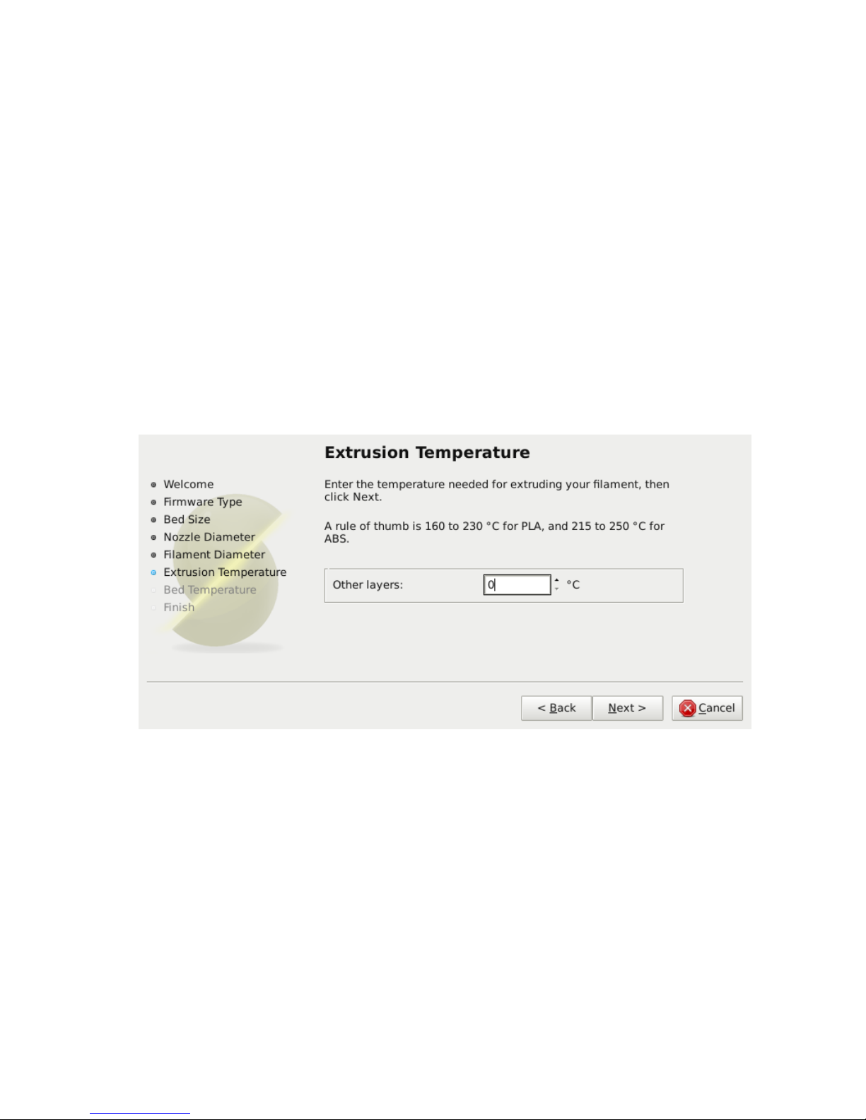
5. Extrusion Temperature
The extrusion temperature will depend on the material, and most can
operate over a range of temperatures. The supplier should provide guidance
as to which temperatures are suitable. A very general rule of thumb is that
PLA lies between 160◦C and 230◦C, and ABS lies between 220◦C and 240◦C.
More exotic materials will have a different range.
This is one parameter which you will want to fine tune when you start
producing prints. The optimal temperature can vary even between colors of
the same material. Another factor which may affect the chosen temperature
is how fast the extrusion is, where generally faster extrusion runs hotter.
Note: One may choose to control the extruder temperature
manually from the printer controller. In this case the temperature
can be set to zero.
Figure 5.6: Configuration Wizard: Extrusion Temperature
69
Page 70
Slic3r
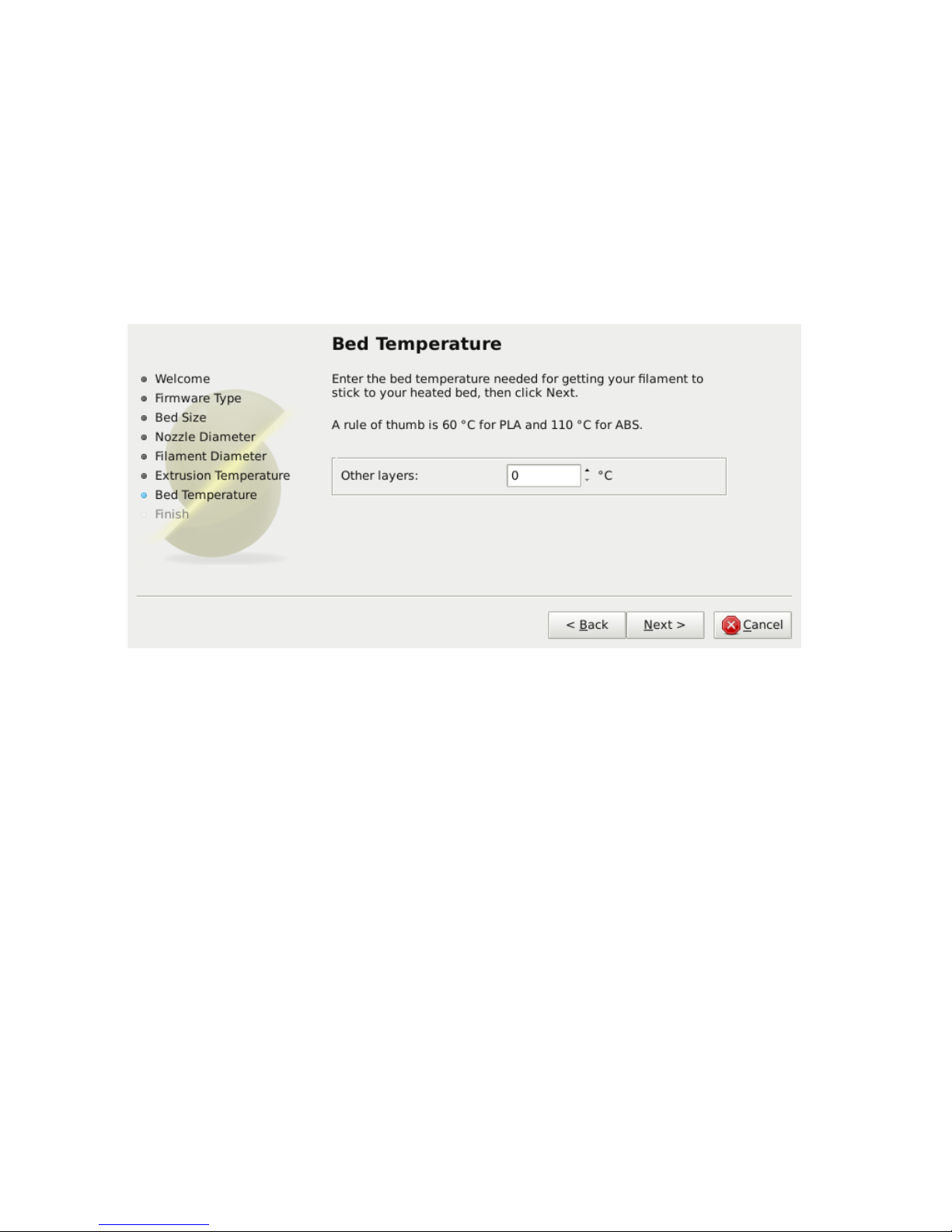
6. Bed Temperature
If the printer has a heated bed then this parameter may be set. As with
the extruder temperature, the value will depend on the material used. A
rule of thumb is that PLA requires 35◦C - 60◦C and ABS requires 85◦C.
Note: One may choose to control the bed temperature manually from the printer controller. In this case the temperature can
be set to zero.
Figure 5.7: Configuration Wizard: Bed Temperature
70
Page 71
5.3. FIRST PRINT
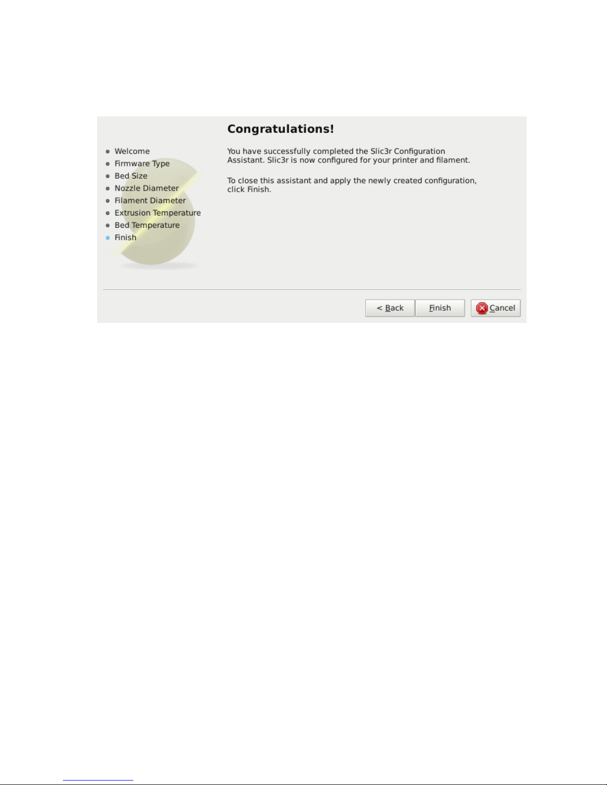
At this stage the wizard is complete and the basic configuration is
defined.
Figure 5.8: Configuration Wizard: End
71
Page 72

Slic3r
The Important First Layer
Before delving into producing the first print it is worthwhile taking a little
detour to talk about the importance of getting the first layer right. As
many have found through trial and error, if the first layer is not the best it
can be then it can lead to complete failure, parts detaching, and warping.
There are several techniques and recommendations one can heed in order
to minimise the chance of this happening.
Level bed.
Having a level bed is critical. If the distance between the
nozzle tip and the bed deviates by even a small amount it can result in
either the material not lying down on the bed (because the nozzle is too
close and scrapes the bed instead), or the material lying too high from the
bed and not adhering correctly.
Higher temperature.
The extruder hot-end and bed, if it is heated,
can be made hotter for the first layer, thus decreasing the viscosity of the
material being printed. As a rule of thumb, an additonal 5◦is recommended.
Lower speeds.
Slowing down the extruder for the first layer reduces the
forces applied to the molten material as it emerges, reducing the chances of
it being stretched too much and not adhering correctly. 30% or 50% of the
normal speed is recommended.
Correctly calibrated extrusion rates.
If too much material is laid
down then the nozzle may drag through it on the second pass, causing it to
lift off the bed (particularly if the material has cooled). Too little material
may result in the first layer coming loose later in the print, leading either
to detached objects or warping. For these reasons it is important to have a
well-calibrated extrusion rate as recommended in §5.3).
First layer height.
A thicker layer height will provide more flow, and
consequently more heat, making the extrusion adhere to the bed more. It
also gives the benefit of giving more tolerance for the levelness of the bed.
It is recommended to raise the first layer height to match the diameter of
the nozzle, e.g. a first layer height of 0.35mm for a 0.35mm nozzle. Note:
The first layer height is set this way automatically in simple mode.
72
Page 73

5.3. FIRST PRINT
Fatter extrusion width.
The more material touching the bed, the better
the object will adhere to it, and this can be achieved by increasing the
extrusion width of the first layer, either by a percentage or a fixed amount.
Any spaces between the extrusions are adjusted accordingly.
A value of approximately 200% is usually recommended, but note that
the value is calculated from the layer height and so the value should only
be set if the layer height is the highest possible. For example, if the layer
height is 0.1mm, and the extrusion width is set to 200%, then the actual
extruded width will only be 0.2mm, which is smaller than the nozzle. This
would cause poor flow and lead to a failed print. It is therefore highly
recommended to combine the high first layer height technique recommended
above with this one. Setting the first layer height to 0.35mm and the first
extrusion width to 200% would result in a nice fat extrusion 0.65mm wide.
Bed material.
Many options exist for the material to use for the bed,
and preparing the right surface can vastly improve first layer adhesion.
PLA is more forgiving and works well on PET, Kapton, or blue painters
tape.
ABS usually needs more cajoling and, whilst it can print well on PET
and Kapton, there are reports that people have success by applying hairspray
to the bed before printing. Others have reported that an ABS slurry (made
from dissolving some ABS in Acetone) thinly applied can also help keep
the print attached.
No cooling.
Directly related with the above, it makes no sense to increase
the temperature of the first layer and still have a fan or other cooling
mechanism at work. Keeping the fan turned off for the first few layers is
generally recommended.
73
Page 74

Slic3r
Working with Models
Yet another step lies between now and the first print - a model has to found
and then sliced.
Model Formats
Slic3r accepts the following file types.
•
STereoLithography (STL) files can come from a wide variety of sources
and are now a de facto standard in 3D printing. The files simply
describe the surface geometry of a 3D object without any additional
information (such as color or material), and it is this simplicity that
has probably made the format ubiquitous.
•
Wavefront OBJ files are an open format originally used in an animation
application from Wavefront Technologies, but has since been adopted
by the wider 3D modelling community. It is similar to the STL format.
•
Additive Manufacturing File Format (AMF) was developed in response
to the limited nature of the STL format. In addition to describing the
geometry of the 3D model it can also describe colors and materials, as
well as more complex attributes, such as gradient mixes and multiple
object arrangements (constellations). Whilst the format is deemed a
standard it has yet to be widely adopted in the 3D maker community.
Finding Models
The 3D model files may come from an online repository, such as Thingiverse
2
or GrabCAD3, or be created from a CAD program, such as FreeCAD4,
Sketchup5, or OpenSCAD6, or an online CAD tool such as Shapesmith7.
You may wish to view the files before slicing and there are many free
applications available, one of which is Meshlab8- a comprehensive tool for
viewing and working with 3D files.
2
http://www.thingiverse.com
3
http://grabcad.com
4
http://sourceforge.net/projects/free-cad
5
http://www.sketchup.com
6
http://www.openscad.org
7
http://shapesmith.net
8
http://www.meshlab.org
74
Page 75
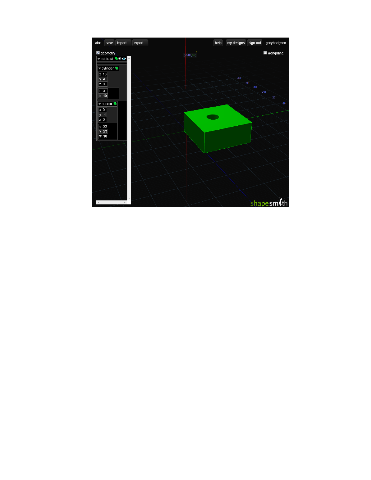
5.3. FIRST PRINT
Figure 5.9: Shapesmith online CAD tool.
Working with Plater
Slic3r has a tool, called Plater, which allows one or more models to be
loaded and arranged before being sliced.
75
Page 76
Slic3r
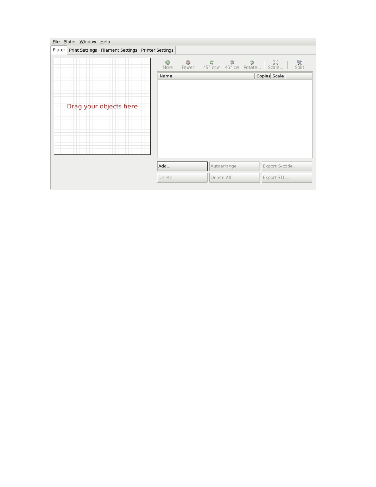
Figure 5.10: Plater
Once you have acquired a model, drag it onto the Plater window (or use
the Add button below the file list) to load it into Slic3r. In the figure below,
the traditional RepRap Minimug9is loaded, and is viewed from above. The
ring around the model is a skirt - a single perimeter, several millimeters
away from the model, which is extruded first. This is useful in making sure
the plastic is flowing smoothly from the nozzle when the model is starting
to be printed.
9
http://www.thingiverse.com/thing:18357
76
Page 77
5.3. FIRST PRINT
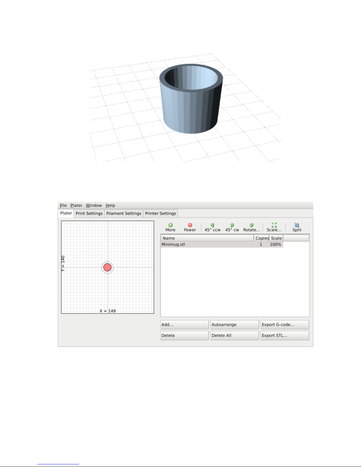
Figure 5.11: Minimug model.
Figure 5.12: STL file loaded.
The model can be repositioned by dragging the representation of it on
the left of the screen around the bed. Note that the dimensions of the bed
should match your printer, as given during the initial configuration above.
77
Page 78

Slic3r
On the right-hand side is the list of currently loaded files. The buttons
along the top of the file list allow you to arrange the models.
• More/Less - Adjust how many copies should be printed.
• 45◦/Rotate
- Rotate the selected model around the Z axis, either in
45◦increments clockwise or counter-clockwise, or by a given amount.
• Scale - Increase or decrease the size of the printed model.
• Split
- Divides a model which consists of more than one part into it’s
constituent parts, allowing each one to be arranged individually.
The buttons along the bottom of the file list allow you to add, remove,
auto-arrange, or export the models.
• Add
- Opens a file dialog to add a model to the plater, as an alternative
to dropping a file directly.
• Delete/Delete All - Remove one or all models from the plater.
• Autoarrange
- Attempt to arrange the models to give the optimal
layout.
• Export G-code
- Starts slicing the model and produces a G-Code
file.
• Export STL - Save the current set of models as a single STL file.
Cleaning STLs
If the 3D mesh described in the model contains holes, or edges are misaligned
(known as being non-manifold), then Slic3r may have problems working on
it. Slic3r will attempt to fix any problems it can, but some problems are
out of its reach. If the application complains that a model cannot be sliced
correctly then there are several options available: see the chapter about
Repairing Models.
78
Page 79
5.4. SIMPLE MODE
Printing
At this stage Slic3r has been configured and a model has been acquired,
sliced and made ready for print. Now would be the time to fire up the
printer and try it out.
A variety of host software is available to send the G-code to the
printer. Amongst the open-source solutions are: Printrun10, Repetier
11
and Repsnapper12.
The following subsections will cover the options available in expert
mode, and look at advanced printing techniques, including special cases and
troubleshooting.
5.4 Simple Mode
Simple Mode
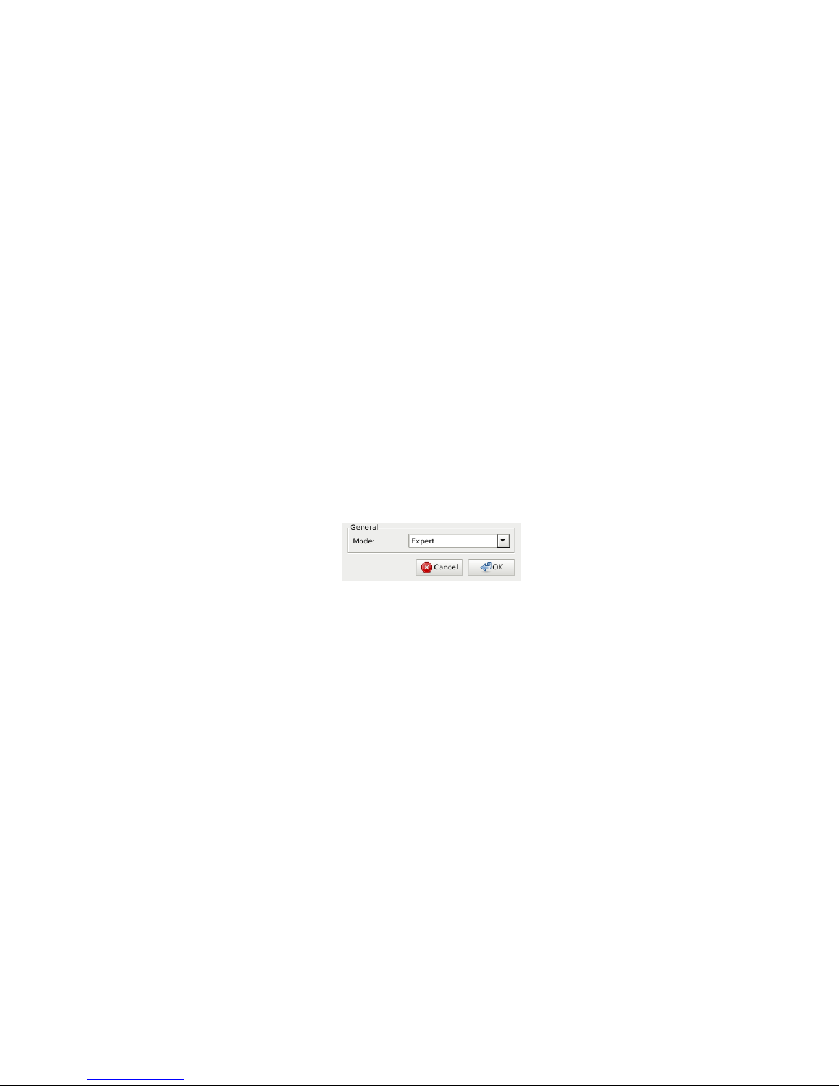
Slic3r has two modes of operation, Simple and Expert. These may be chosen
from the Preferences window (found under the File menu).
Figure 5.13: Preferences.
Simple mode offers a reduced set of options, enough for the beginner to
get started with. Expert mode gives more control over how Slic3r produces
the G-code and will be looked at later.
Print Settings
The
Print Settings
tab provides the opportunity to change settings related
to the actual print. Whereas the other tabs are changed rarely, the settings
on this tab will be modified regularly, possibly for each model printed.
10
https://github.com/kliment/Printrun
11
http://www.repetier.com/
12
https://github.com/timschmidt/repsnapper
79
Page 80
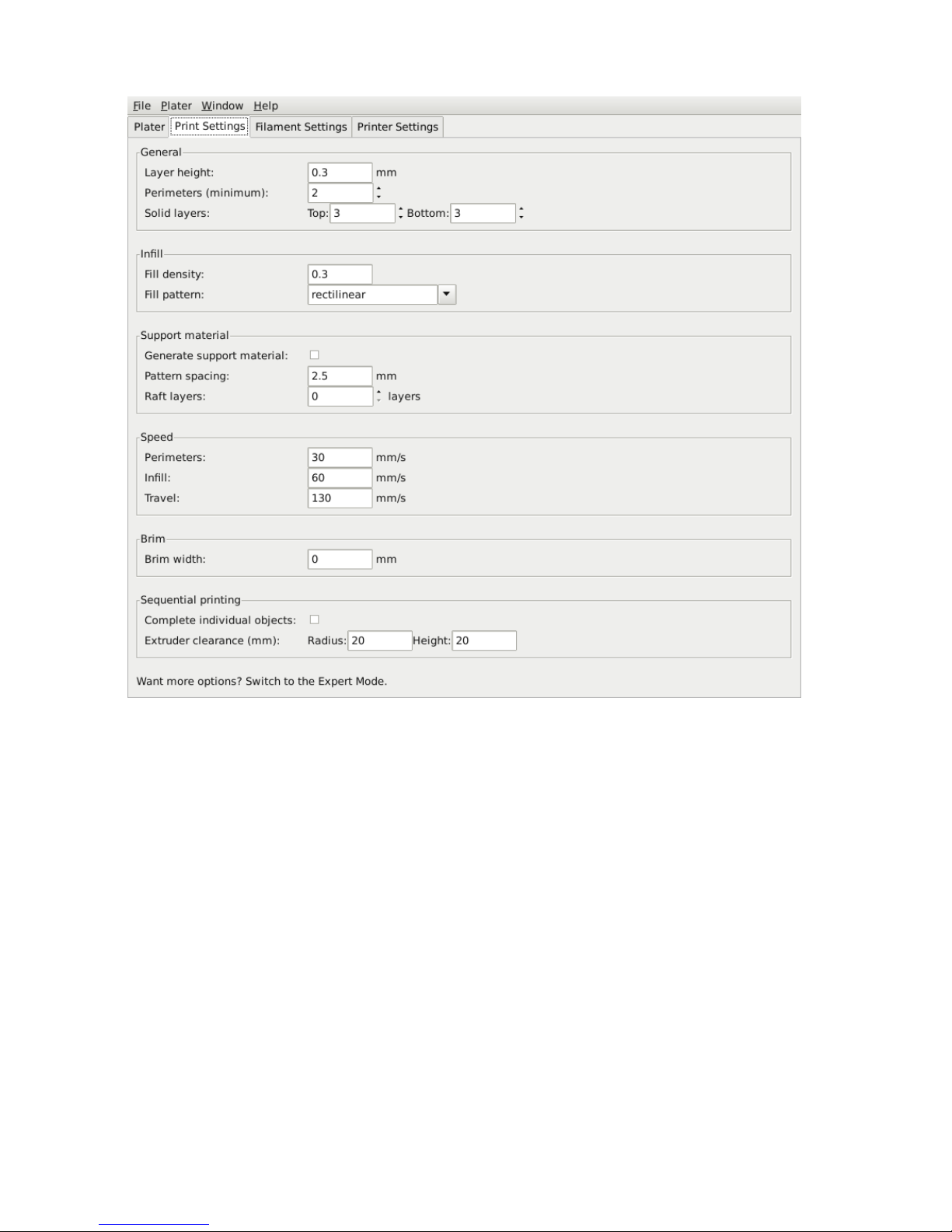
Slic3r
Figure 5.14: Simple Mode: Print Settings.
General. Layer height
is the thickness of each layer, and it is the step
along the vertical axis taken before extruding a new layer atop the previous
one. There are several factors that influence how high each layer should be:
• Desired resolution
- Lower layer height should result in prints with
less noticeable ribs or bands, as each layer is smaller. Aesthetics plays
a role here, but also the type of model, for example, a mechanical part
may not need such a high resolution finish, whereas a presentation
piece may do so.
80
Page 81
5.4. SIMPLE MODE
• Print speed
- Shorter layers will result in smoother prints but each
print will take longer, simply because the extruder must trace the
pattern more times. A later goal will be to strike a balance between
layer height, the speed of the printer, and the quality of the resulting
print.
Perimeters
defines the minimum number of vertical shells (i.e. walls) a
print will have. Unless the model requires single width walls it is generally
recommended to have a minimum of two perimeters as this gives some
insurance that if a subsection of the perimeter is not printed correctly then
the second perimeter will help cover it.
The upper and lowermost layers that sandwich the model are filled with
a
Solid layers
pattern. For the bottom layers the important factor to
consider is how the surface will look should there be a mistake whilst laying
down the first layer, and for this reason it is recommended to have at least
two bottom layers.
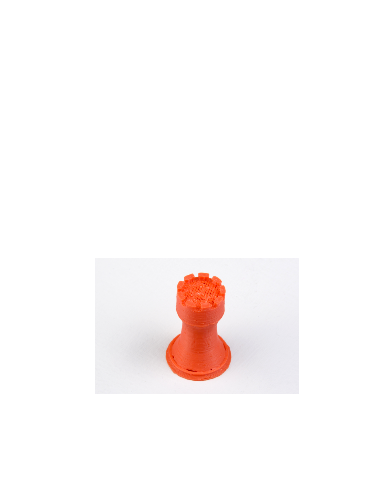
A similar consideration is required for the top layers. Because the
intermediate layers are likely to be filled with a pattern set less than 100%
then the covering layers will have to bridge this pattern and this can require
more than one pass to cover completely.
Figure 5.15: An example of insufficient top layers.
81
Page 82
Slic3r
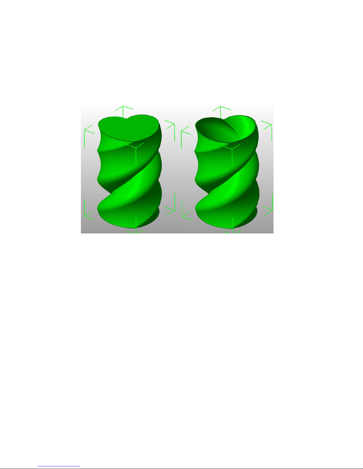
Another tip to consider: Setting the top solid layer to zero, and setting
the infill also to zero, will result in a hollow receptacle, ideal for turning
models into vases13for example. Here manipulating the settings within
Slic3r can be used to generate different kinds of prints, and not only be
used to control surface accuracy.
Figure 5.16: Creating a vase from a solid model.
Infill. Fill density
is defined on a scale of between 0 and 1, where 1 is
100% and 0.4 would be 40%. For the majority of cases it makes no sense to
100% fill the model with plastic, this would be a waste of material and take
a long time. Instead, most models can be filled with less material which is
then sandwiched between layers filled at 100% (see Solid layers above).
A density value of 0.4 is enough to give almost all models good mechanical
strength. A value of 0.2 is usually the minimum required to support flat
ceilings.
Slic3r offers several fill patterns which will be discussed in more depth
in subsection 5.5 - Infill Choices. Choosing a
Fill pattern
will depend on
the kind of model, the desired structural strength, print speed, and personal
taste. The more exotic fill methods are usually too slow and unnecessarily
complex for most use cases, and so most of the time the infill pattern is either
13
http://slic3r.org/blog/tip-printing-vases
82
Page 83
5.4. SIMPLE MODE
rectilinear,line
, or
honeycomb
. Honeycomb gives the most strength
but is slower than both rectilinear or line.
Support material.
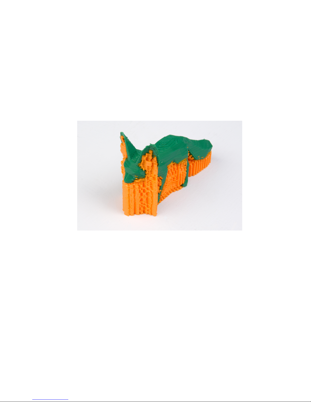
Printing a model from the bottom up, as with FDM,
means that any significant overhangs will be printed in the air, and most
likely droop or not print correctly. Choosing support material (
Generate
support material
) will add additional structures around the model which
will build up to then support the overhanging part. The
Pattern spacing
option determines how dense the support material is printed.
Figure 5.17: An example of an object printed with support material.
Tip: It is sometimes worth considering altering the orientation of the
model in order to possibly reduce overhangs.
Raft layers
will add additional layers underneath the model and stems
from the early days of 3D printing. It can help with prints without a heated
bed, or where the bed is not very flat, but it is usually not required and is
not recommended. The raft also requires post-processing to remove it.
Speed.
In simple mode there are only three speed settings to consider:
• Perimeters
- The outline of the model may benefit from being printed
slightly slower so that the outside skin of the print has fewer blemishes.
83
Page 84
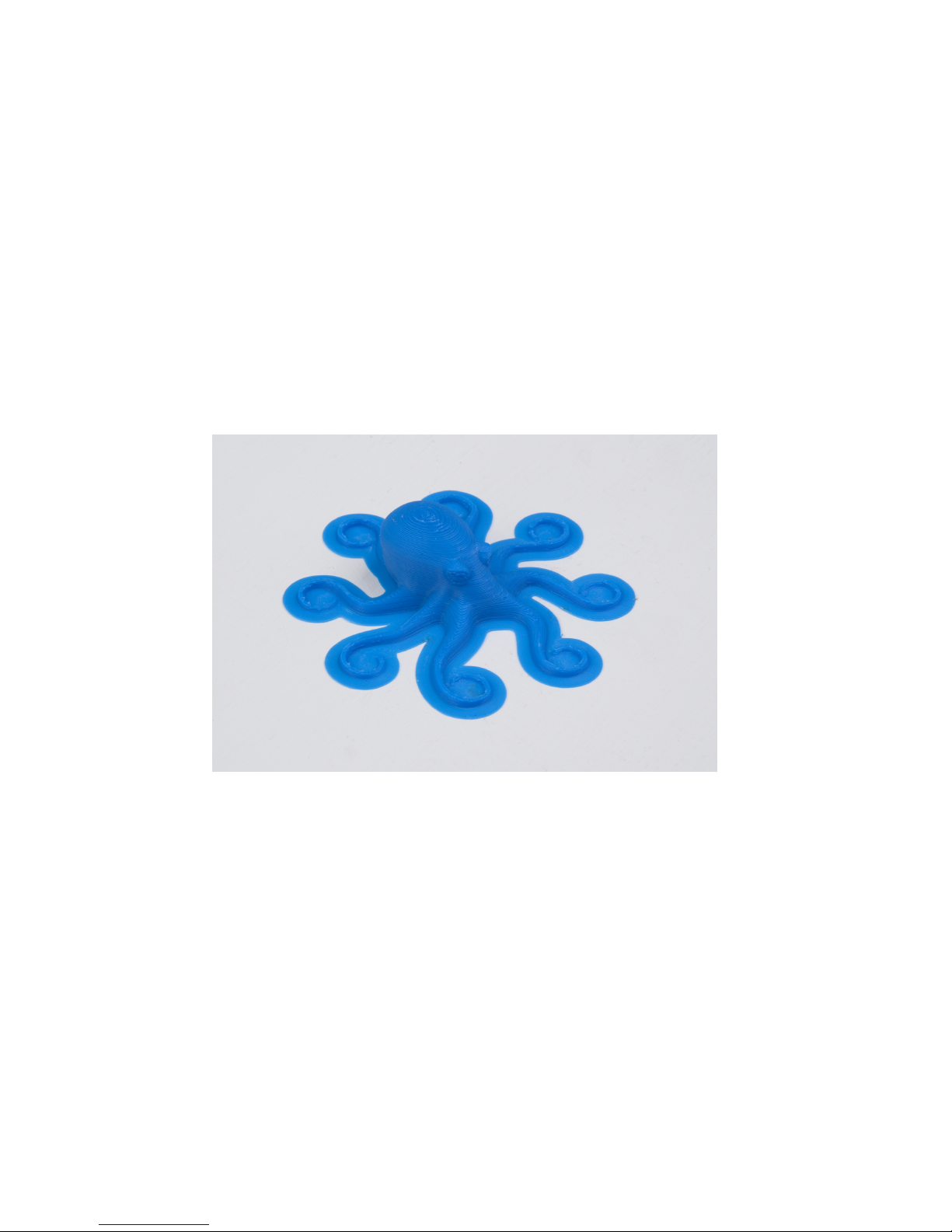
Slic3r
• Infill
- As the infill is hidden this can be extruded a little faster.
Take care though not to go too fast as higher speeds results in thinner
extrusions, and this may affect how the extrusions bond.
• Travel
- The jump between the end of one extrusion and the next
should usually be performed as quickly as the printer will allow in
order to minimise any mess caused by material oozing from the nozzle.
Brim. Brim width
is used to add more perimeters to the first layer, as a
base flange, in order to provide more surface area for the print to stick to
the bed with in order to reduce warping (see§5.3). The brim is then cut
away once the print is finished and removed from the bed.
Figure 5.18: An example of brim.
Sequential Printing.
This feature allows to compose a plate of objects
but have the printer complete each one individually before going back to Z
= 0 and starting with the next one. See the subsection about Sequential
Printing in the Advanced Topics chapter.
Filament Settings
The
Filament Settings
will normally be used infrequently, for example
on receipt of a new roll of filament.
84
Page 85
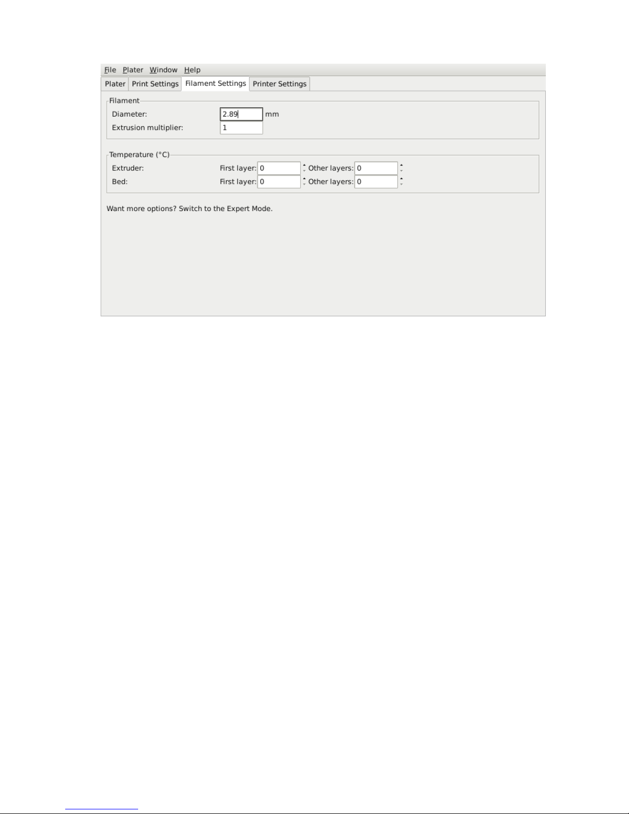
5.4. SIMPLE MODE
Figure 5.19: Simple Mode: Filament Settings.
Filament.
The
Diameter
setting will already have been filled from the
value given during the wizard (see p.68), but can be updated here.
The
Extrusion multiplier
setting allows the fine tuning of the
extrusion flow rate, and is is given as a factor, e.g. 1 means 100%, 1.5 would
mean 150%. Whilst the value should ideally be set in the firmware it can
be useful to test slight changes to the rate by altering this value. It varies
the amount of plastic proportionally and should be changed in very small
steps (e.g. +/- 0.05) as the effects are very visible.
Temperature.
These values are also filled from the wizard, but here the
opportunity exists to set the temperature for the first layer (see p.72).
Printer Settings
The
Printer Settings
will be updated the least, unless Slic3r is going to
be used for many printers, for example, in a 3D printer farm.
85
Page 86
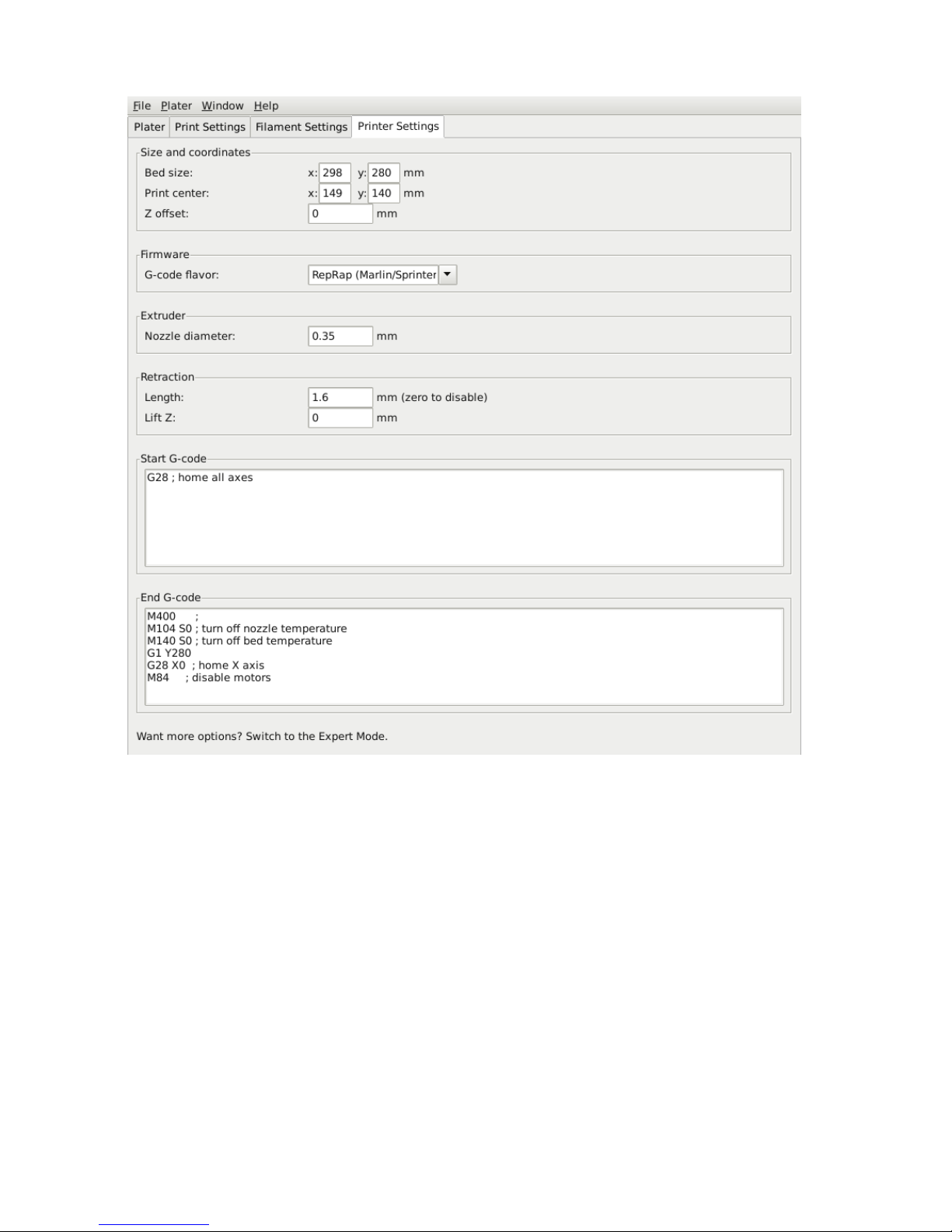
Slic3r
Figure 5.20: Simple Mode: Printer Settings.
Size and coordinates.
The
Bed size
setting is taken from the wizard
(see p.66) and is only used for previewing the model in the plater.
The
Print center
is the point around which the print will be centered.
A
Bed size
of 200mmx200mm and a
Print center
of 100mmx100mm
would sit the print in the middle. Should it be desired to print away from
the center, because of a scratch in the glass perhaps, then this option should
be used.
Z offset
can be used to compensate for an incorrectly calibrated Z
end-stop. If the nozzle stops slightly too far from the bed, then adding a
86
Page 87

5.4. SIMPLE MODE
negative value will offset all layers by that amount. The correct solution
however is to fix the end-stop itself.
The optimal Z endstop position is where the nozzle tip barely touches
the surface of the bed when homed. A sheet of paper makes a good gauge
for this very small distance. It is not recommended to use this setting to
try and improve layer adhesion, by ”squashing” the bottom layer into the
bed, instead look at the suggestions in subsection 5.3.
Firmware.
As selected in the wizard (see p.65),
G-code flavour
defines
the dialect of G-code generated.
Extruder. Nozzle diameter was defined in the wizard (see p.67).
Retraction.
Unless the material being extruded has a very high viscosity
it may ooze between extrusions due to gravity. This can be remedied by
actively retracting the filament between extrusions. Setting the
Length
parameter to a positive value will cause the filament to be reversed by that
many millimeters before travel. The retraction will then be compensated for
by the same amount after the travel move, before starting the new extrusion
path.
A value of between 1 and 2mm is usually recommended. Bowden
extruders may need up to 4 or 5mm due to the hysteresis introduced by
the tube. Setting the
Lift Z
parameter to a positive value will raise the
entire extruder on the Z axis by that many millimeters during each travel.
This can be useful to ensure the nozzle will not catch on any already laid
filament, however it is usually not necessary and will slow the print speed.
A value of 0.1mm is usually sufficient.
Start, End and Layer Chance G-codes.
Custom G-code commands
can be run before a print starts and after a print finishes.
Placeholders can be inserted in the G-code commands14. For example
[next extruder] would return the index of the next extruder.
The RepRap wiki is a good resource to learn about the variety of G-codes
available: http://reprap.org/wiki/G-code.
Note: Be sure to check that a given G-code is valid for your firmware.
14
https://github.com/alexrj/Slic3r/wiki/FAQ#what-placeholders-can-i-use-in-
custom-g-code
87
Page 88

Slic3r
The codes specified in
Start G-code
are inserted at the beginning of the
output file, directly after the temperature control commands for extruder
and bed. Note that if temperature control commands are specified (M104
and M190) then these will replace the temperature G-codes introduced by
the Filament settings.
Some common G-codes to use before the print starts are:
• G28 - Homes all the axes.
Some common G-codes to use after the print ends are:
• M104 S0 - Sets the extruder temperature to zero.
• M140 S0 - Sets the heated bed temperature to zero.
• G28 X0 - Home the X axis.
• M84 - Disables the motors.
5.5 Expert Mode
Speed
Once the printer is reliably producing good quality prints it may be desirable
to increase the speed. Doing this provides several benefits, the most obvious
of which is that the results are produced quicker, but also faster print
times can be utilised in producing more layers, i.e. lower layer height, thus
improving perceived print quality. An additional benefit is that a faster
travel movement, between extrusions, can reduce the effects of oozing.
The best approach is to increment the various speed parameters in small
steps and observe the effect each change has on print quality. Travel speed
is a safe starting point, and it is not unrealistic to attain speeds of up to
250mm/s (if your printer can handle it). Adjusting the speed of perimeters,
infill is available in simple mode, and the general rule is to have the perimeter
go a little slower than the infill in order to reduce possible blemishes on the
surface (infill can be faster because slight gaps will not matter as much).
Expert mode offers more parameters to fine tune printer speeds. Differentiation between external, small and other perimeters, infill locations, and
bridges and gaps are available, as well as the ability to slow down for the
first layer.
88
Page 89
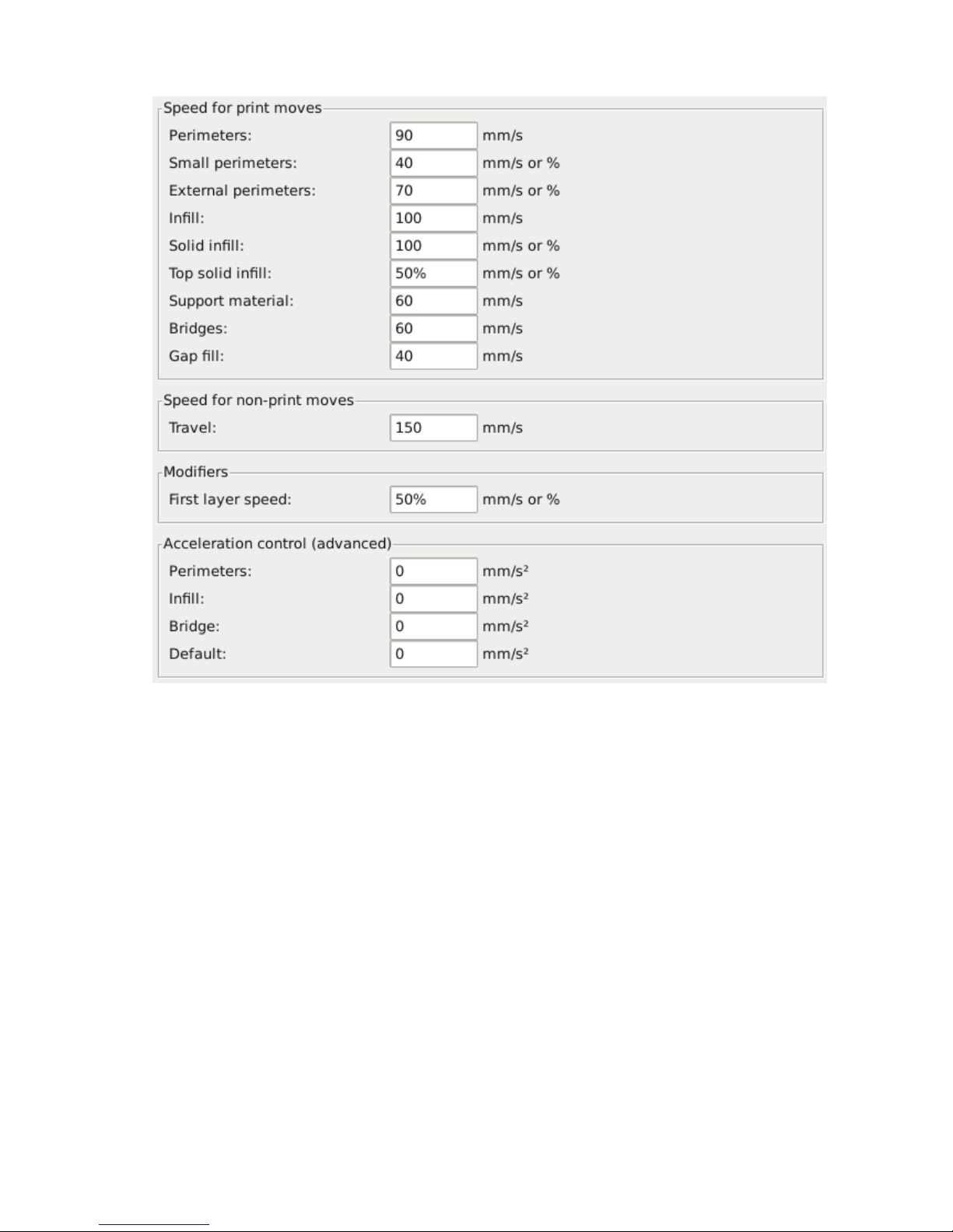
5.5. EXPERT MODE
Figure 5.21: Expert mode speed options.
Where indicated a value can be given in percentage. This is in relation
to the preceding value, e.g. 50% solid infill would be half of the value defined
for infill.
A few general guidelines for each option:
• Perimeters
- In expert mode this parameter can be increased slightly
as the
External perimeters
option can be used to ensure blemish
free external faces.
• Small perimeters
- Meant for holes, islands and fine details, a slower
speed here is recommended.
• External perimeters
- A slightly slower value may ensure cleaner
surfaces.
89
Page 90

Slic3r
• Infill
- As fast as you can without compromising the integrity of the
fill structure. Faster extrusions can break and result in weak spots.
• Solid infill
- The bottom of the model, and any additional solid
layers is usually slightly slower than infill but faster than perimeters.
• Top solid infill
- Allow time for the extrusion to cleanly cover
the previous top layers and result in a tidy top surface. The last few
layers should have bridged the infill structure nicely, preparing the
way for a neat finish.
• Support material
- Generally support structures are quick and dirty,
and so long as the base is adequately supported they can be built as
quickly as they can.
• Bridges
- Having the extrusion span distances depends on the material
and cooling. Going too slow will result in sagging, too fast will result
in broken strands. Experimentation is the key here, but generally
bridging runs slower than perimeters.
• Gap fill
- Filling in small gaps results in the extruder quickly
oscillating and the resulting shaking and resonance could have a
detrimental affect on the printer. A smaller value here can guard
against this. A setting of zero disables gap filling completely.
• Travel
- As fast as your printer will allow in order to minimise ooze.
• First layer speed
- As mentioned in subsection 5.3, the first layer
is important to lay down correctly, and a slower pace helps enormously.
Setting a value of 50%, or even less, can really help.
Acceleration control
is an advanced setting allowing acceleration
settings for perimeters, infill, bridge, as well as a default setting, to be made.
Deciding which values to set depends on the capabilities of the machine.
Any settings within the firmware may be a good starting point.
Take into account any restrictions enforced by the firmware as many
have settings for the maximum safe speed of each axis.
90
Page 91
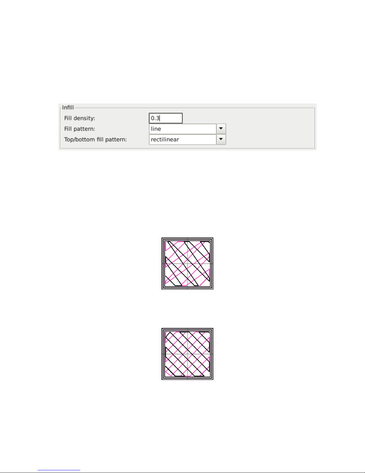
5.5. EXPERT MODE
Infill Patterns and Density
There are several considerations when choosing an infill pattern: object
strength, time and material, personal preference. It can be inferred that a
more complex pattern will require more moves, and hence take more time
and material.
Figure 5.22: Infill pattern settings.
Slic3r offers several infill patterns, four regular, and three more exotic
flavours. The numbers given in brackets below each figure are a rough
estimate of material used and time taken for a simple 20mm cube model15.
Note that this is only indicative, as model complexity and other factors will
affect time and material.
Figure 5.23: Infill pattern: Line (344.51mm / 5m:20s)
Figure 5.24: Infill pattern: Rectilinear (350.57mm / 5m:23s)
15
Taken from http://gcode.ws
91
Page 92
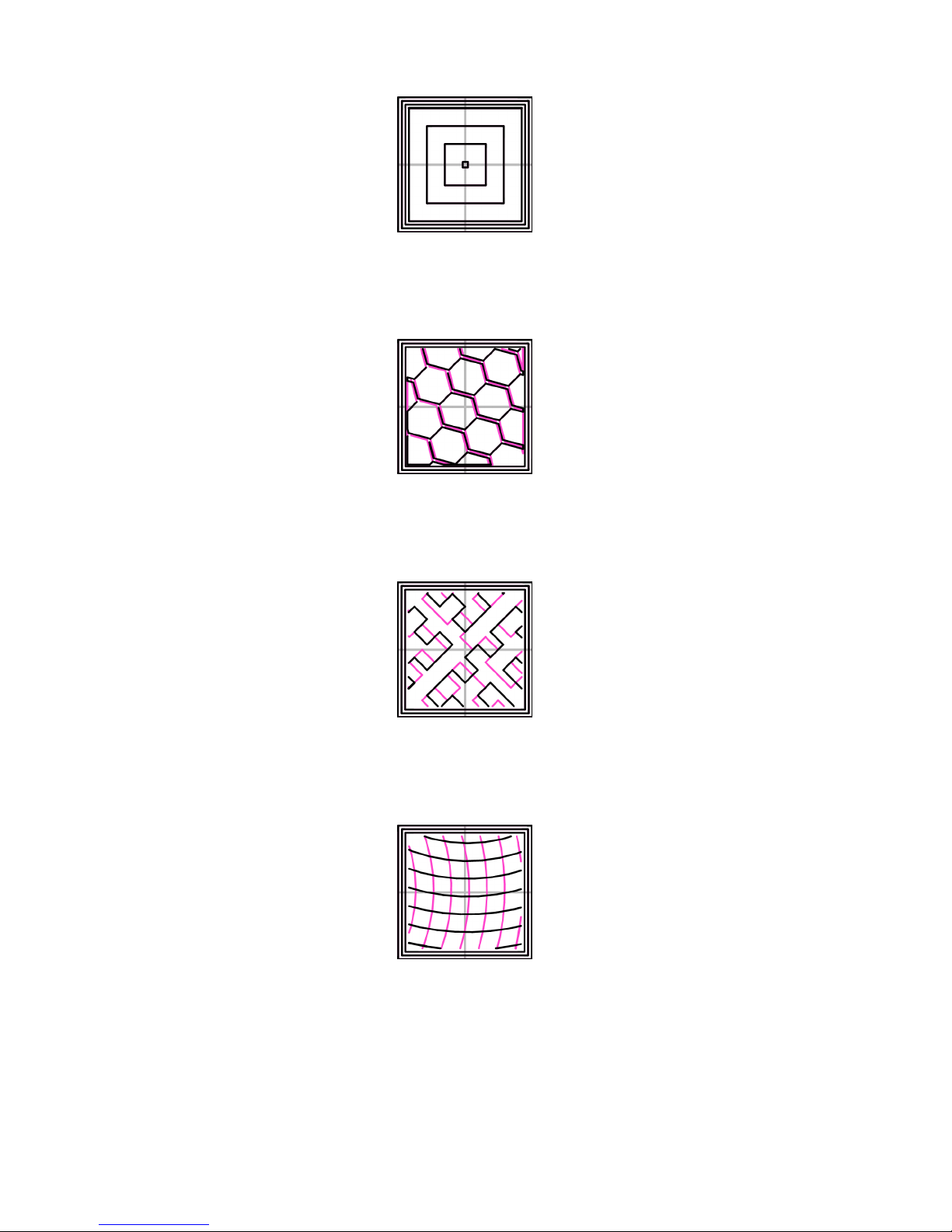
Slic3r
Figure 5.25: Infill pattern: Concentric (351.80mm / 5m:30s)
Figure 5.26: Infill pattern: Honeycomb (362.73mm / 5m:39s)
Figure 5.27: Infill pattern: Hilbert Curve (332.82mm / 5m:28s)
Figure 5.28: Infill pattern: Archimedean Chords (333.66mm / 5m:27s)
92
Page 93
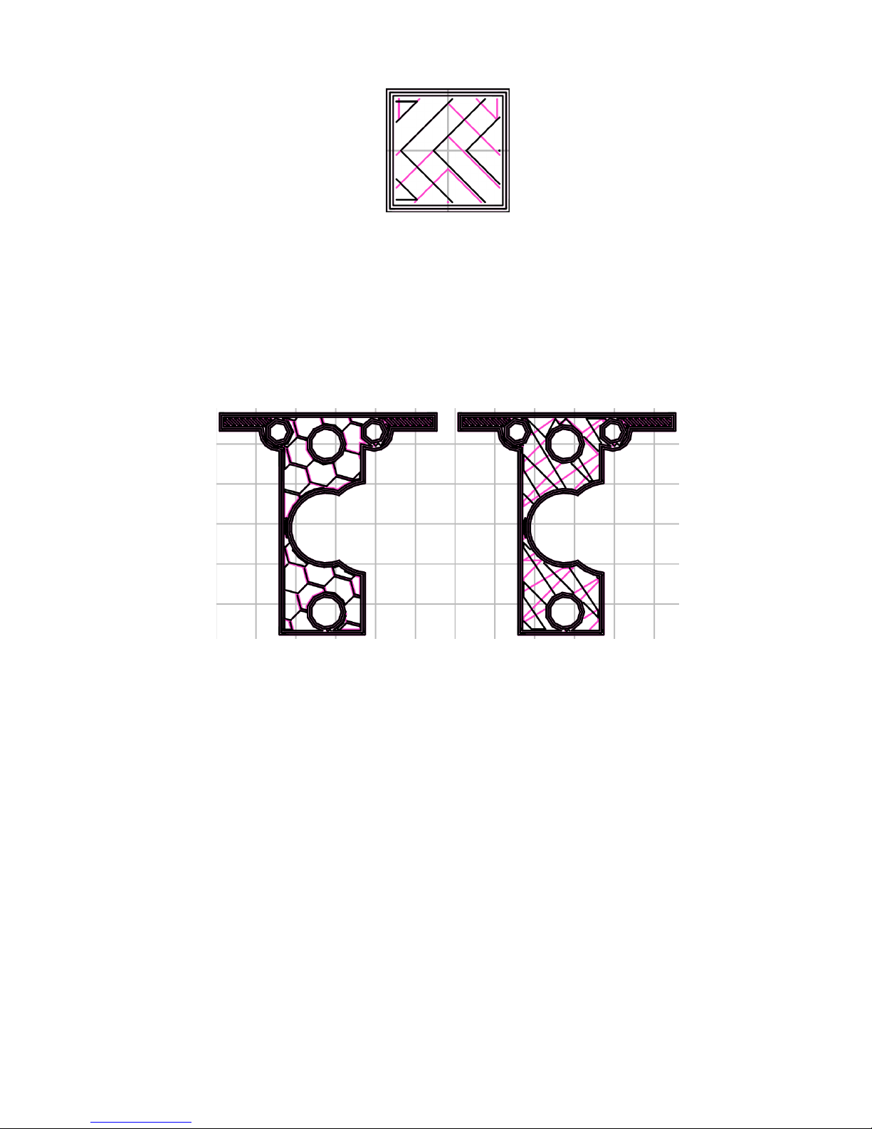
5.5. EXPERT MODE
Figure 5.29: Infill pattern: Octagram Spiral (318.63mm / 5m:15s)
Certain model types are more suited for a particular pattern, for example
organic versus mechanical types. Figure 5.30 shows how a honeycomb fill
may suit this mechanical part better because each hexagon bonds with the
same underlying pattern each layer, forming a strong vertical structure.
Figure 5.30: Infill pattern comparison in a complex object. Left to Right:
honeycomb, line
Most models require only a low density infill, as providing more than,
say, 50% will produce a very tightly packed model which uses more material
than required. For this reason a common range of patterns is between
10% and 30%, however the requirements of the model will determine which
density is best. Figure 5.31 shows how the patterns change as the density
increases.
93
Page 94
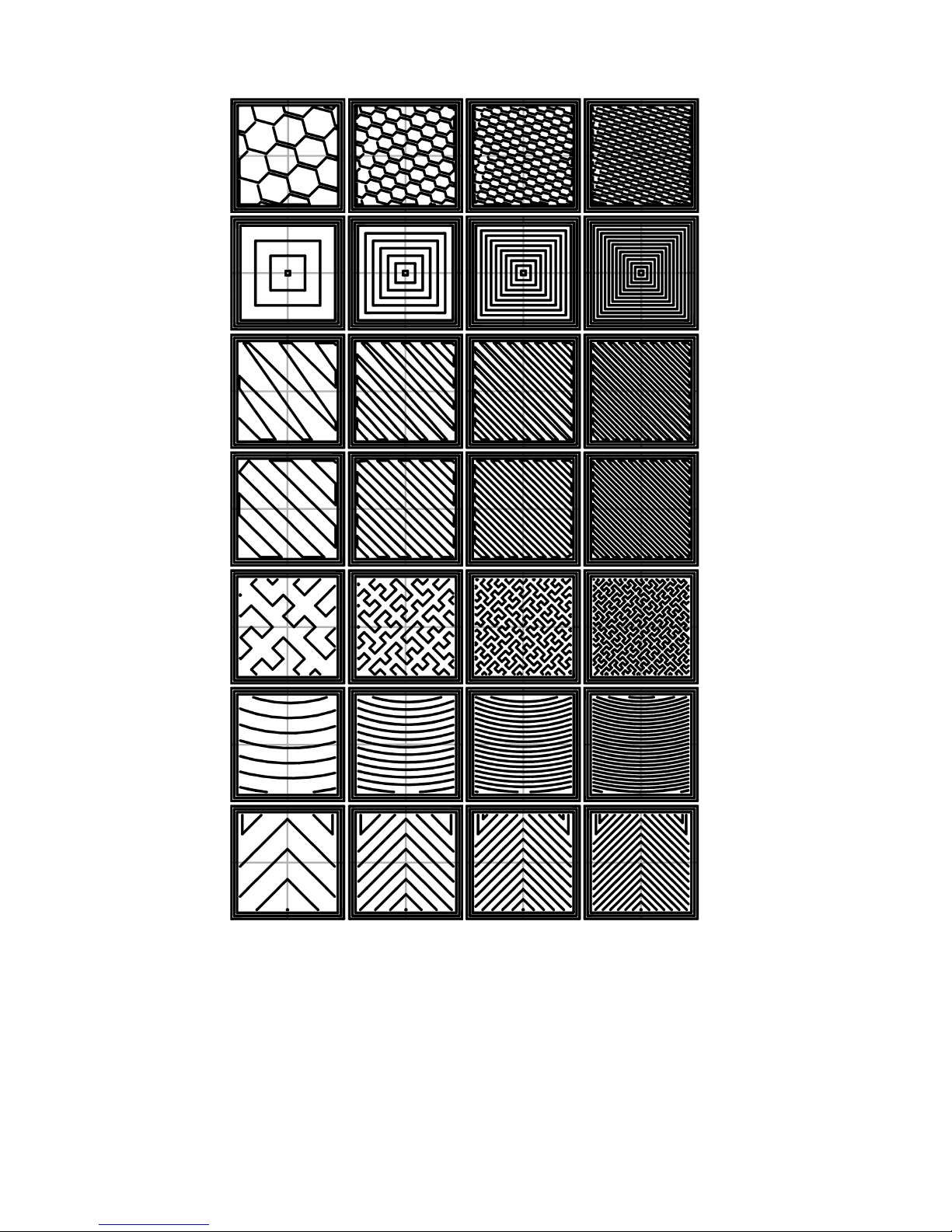
Slic3r
Figure 5.31: Infill patterns at varying densities. Left to Right:
20%,40%,60%,80%. Top to Bottom: Honeycomb, Concentric, Line, Recti-
linear, Hilbert Curve, Archimedean Chords, Octagram Spiral
94
Page 95
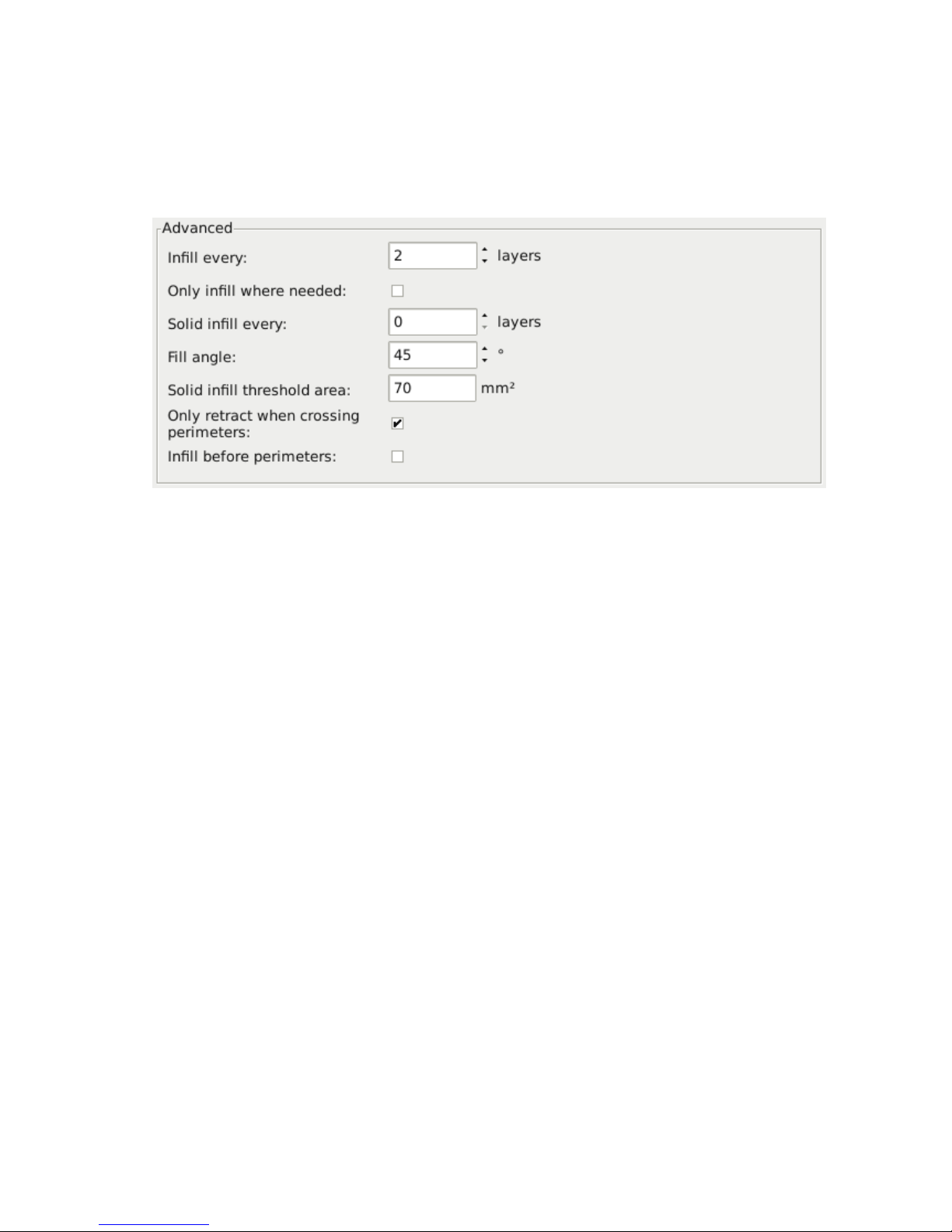
5.5. EXPERT MODE
Infill Optimization
Slic3r contains several advanced infill settings which can help produce better
extrusions.
Figure 5.32: Infill advanced settings.
• Infill every n layers
- Will produce sparse vertical infill by
skipping a set number of layers. This can be used to speed up print
times where the missing infill is acceptable.
• Only infill where needed
- Slic3r will analyse the model and
choose where infill is required in order to support internal ceilings and
overhangs. Useful for reducing time and materials.
• Solid infill every n layers
- Forces a solid fill pattern on the
specified layers. Zero will disable this option.
• Fill angle
- By default the infill pattern runs at 45◦to the model to
provide the best adhesion to wall structures. Infill extrusions that run
adjacent to perimeters are liable to de-laminate under stress. Some
models may benefit from rotating the fill angle to ensure the optimal
direction of the extrusion.
• Solid infill threshold area
- Small areas within the model are
usually best off being filled completely to provide structural integrity.
This will however take more time and material, and can result in parts
being unnecessarily solid. Adjust this option to balance these needs.
95
Page 96
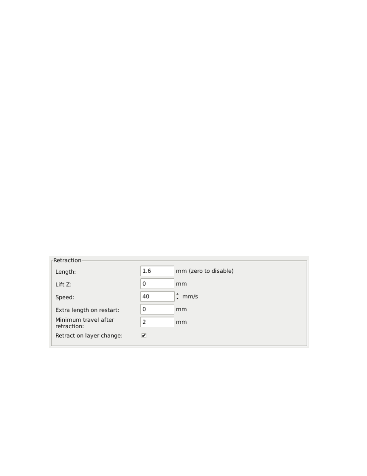
Slic3r
• Only retract when crossing perimeters
- Retracting, to prevent
ooze, is unnecessary if the extruder remains within the boundaries of
the model. Care should be taken if the print material oozes excessively,
as not retracting may result in enough material loss to affect the
quality of the subsequent extrusion. However, most modern printers
and materials rarely suffer from such extreme ooze problems.
• Infill before perimeters
- Reverses the order in which the layer
is printed. Usually the perimeter is laid down initially, followed by
the infill, and this is usually the preferable as the perimeter acts as a
wall containing the infill.
Fighting Ooze
Unless the material being extruded has a very high viscosity it will ooze
from the nozzle in between extrusions. There are several settings in Slic3r
to which can help to remedy this.
The retraction settings, found in the
Printer
tab, tell the printer to pull
back the filament between extrusion moves. This can alleviate the pressure
in the nozzle, thus reducing ooze. After the subsequent travel move the
retraction is reversed to prepare the extruder for the next extrusion.
Figure 5.33: Retraction settings.
• Length
- The number of millimeters to retract. Note that the
measurement is taken from the raw filament entering the extruder.
A value of between 1 and 2mm is usually recommended. Bowden
96
Page 97

5.5. EXPERT MODE
extruders may need up to 4 or 5mm due to the hysteresis introduced
by the tube.
• Lift Z
- Raises the entire extruder on the Z axis by that many
millimeters during each travel. This can be useful to ensure the nozzle
will not catch on any already laid filament, however it is usually not
necessary and will slow the print speed. A value of 0.1mm is usually
sufficient.
• Speed
- The speed at which the extruder motor will pull back the
filament. The value should be set to as quick as the extruder can
handle without skipping steps, and it is worth experimenting with
this value to find the quickest retraction possible.
• Extra length on restart
- Adds an extra length of filament after
the retraction is compensated after the travel move. This setting
is rarely used, however should the print show signs of not having
enough material after travel moves then it may be useful to add a
small amount of additional material.
• Minimum travel after retraction
- Triggering a retraction after
very short moves is usually unnecessary as the amount of ooze is usually
insignificant and it slows down the print times. Set the number of
millimeters minimum distance the nozzle must move before considering
a retraction. If the printer handles ooze well this can be increased to
5 or 6mm.
• Retract on layer change
- Movement along the Z axis must also
be considered when dealing with oozing, otherwise blobs may occur.
It is recommended to leave this setting on.
• Wipe before retract
- Moves the nozzle whilst retracting so as to
reduce the chances of a blob forming.
Additionally there are several settings in the
Print
tab which can help
control oozing.
• Only retract when crossing perimeters
(Infill) - Tells Slic3r to
only retract if the nozzle will cross the threshold of the current island
being extruded. Slight ooze within the walls of a part are not seen
and can usually be accepted.
97
Page 98
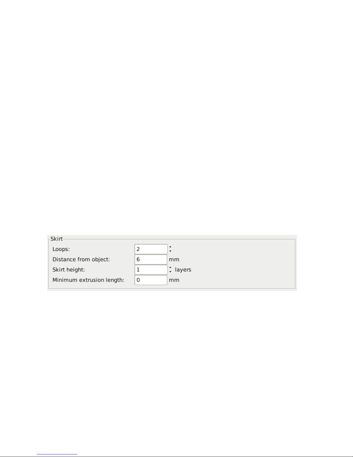
Slic3r
• Avoid crossing perimeters
(Layers and perimeters - Advanced)
- Will force the nozzle to follow perimeters as much as possible to
minimise the number of times it must cross them when moving around,
and between, islands. This has a negative impact on both G-code
generation and print times.
• Randomize starting points
(Layers and perimeters - Vertical shells)
- As the extruder moves up to the start of the next layer any ooze can
result in blobs. If the same start point is used for every layer then a
seam can form the length of the object. This setting will move the
start point to a different location for each layer.
See also subsection: Sequential Printing, on page 119 for another
technique which can minimise strings forming between objects.
Skirt
The
Skirt
setting adds an extrusion a short distance away from the perimiter
of the object. This can ensure that the material is flowing smoothly from
the extruder before it starts on the model proper.
Figure 5.34: Skirt settings.
• Loops
- How many circuits should be completed before starting on
the model. One loop is usually sufficient.
• Distance from object
- The millimeters between the object and the
skirt. The default of 6mm is usually sufficient.
• Skirt height
- The number of layers to lay down a skirt for. For
ensuring the material is flowing smoothly, one layer is sufficient,
98
Page 99
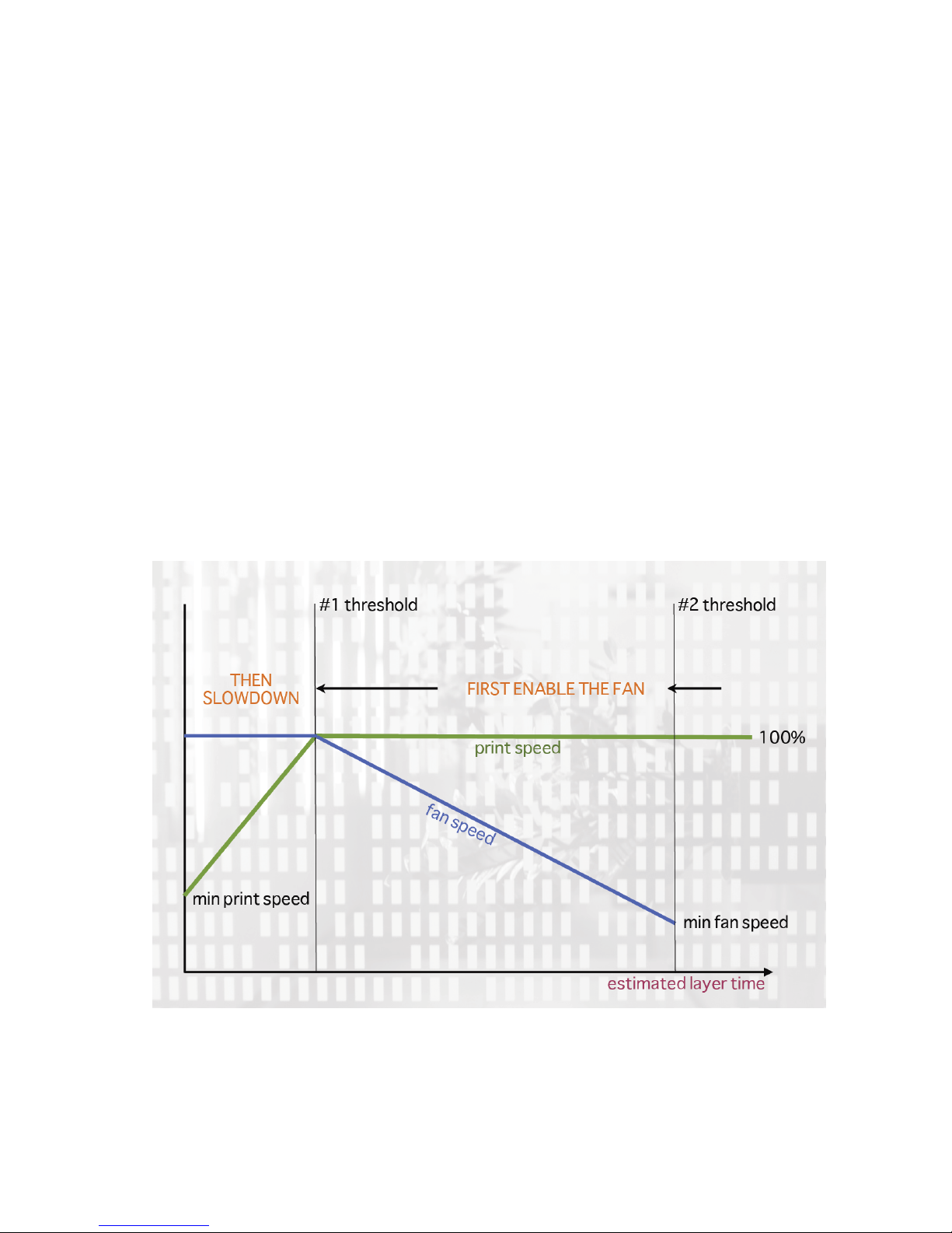
5.5. EXPERT MODE
however the skirt function can also be used to build walls around the
object in case it should be protected from drafts.
• Minimum extrusion length
- Dictates a minimum number of millimeters that the skirt should be, should the loop around the object
not be enough.
Cooling
Temperature plays a key part in determining print quality. Too hot and the
material deforms, too cool and layer adhesion may be problematic. Applying
cooling will allow the freshly deposited material to solidify enough to provide
a good base for the next layer, helping with overhangs, small details and
bridges.
There are two main techniques for cooling: adding a fan and slowing
down the print speed. Slic3r may choose to use both techniques, using a
fan first, and then slowing down the print if the layer time is too fast.
Figure 5.35: Cooling strategy.
99
Page 100

Slic3r
Figure 5.35 shows the strategy adopted by Slic3r. Reading from right
to left, when the minimum fan threshold (#2) is reached the fan is turned
on. This increases in intensity as the layer time decreases. The print
speed remains constant until the estimated print time drops below a certain
threshold (#1), this is when the print speed is reduced until it reaches it’s
minimum value.
Fans
Most electronics and firmware allow the addition of a fan via a spare
connector. These can then be instructed with G-code, from Slic3r, to turn
on or off as the model requires, and to rotate at different speeds.
Care should be taken with the positioning of the fan so that it does not
cool any heated bed more than necessary. It should also not cool the heater
block of the hot-end so as not to force it to do more work and waste energy.
The air movement should aim for the nozzle tip, flowing over the freshly
extruded material.
A duct may help in guiding the flow correctly, and there are several
designs available online, for a wide variety of printers.
Slowing Down
Slic3r can tell the printer to slow down if the estimated layer time is above
a certain threshold.
Care must be taken as the intended effect could be mitigated by the
nozzle not moving far enough away from the fresh extrusion, a problem
with small, detailed layers. For this reason it is usually recommended to
use a fan where possible.
Configuring
In simple mode Slic3r will attempt to choose the optimal settings for both
fans and speed. Expert mode gives more granular options.
100
 Loading...