

Page 1

Operators and Safety Manual
Model
644B
10709799
May 1997
ANSI
Page 2

Page 3

CONTENTS
Section Page No.
INTRODUCTION . . . . . . . . . . . . . . . . . . . . . . . . . . . . . . . . . . . . . . . . . . . . . . . . . . . . . . . ii
SAFETY. . . . . . . . . . . . . . . . . . . . . . . . . . . . . . . . . . . . . . . . . . . . . . . . . . . . . . . . . . . . . .1
INSTRUMENTS AND CONTROLS. . . . . . . . . . . . . . . . . . . . . . . . . . . . . . . . . . . . . . . . . 8
BEFORE OPERATING THE MACHINE . . . . . . . . . . . . . . . . . . . . . . . . . . . . . . . . . . . . 1 9
GENERAL OPERATING PROCEDURES. . . . . . . . . . . . . . . . . . . . . . . . . . . . . . . . . . . 21
FLUID AND LUBRICANT SPECIFICATIONS . . . . . . . . . . . . . . . . . . . . . . . . . . . . . . . 26
SERVICE/LUBRICATION SCHEDULE. . . . . . . . . . . . . . . . . . . . . . . . . . . . . . . . . . . . . 28
SAMPLE LOAD CHART. . . . . . . . . . . . . . . . . . . . . . . . . . . . . . . . . . . . . . . . . . . . . . . . 32
SAFETY ALERT SYMBOL
This Safety Alert Symbol means:
ATTENTION! BECOME ALERT! YOUR SAFETY IS INVOLVED!
When you see this symbol, be alert to the possibility of personal
injury or death. Follow the instructions in the safety message.
Three Reasons Why Safety is Important to You:
1. Accidents disable and kill.
2. Accidents cost.
3. Accidents can be avoided.
W1027
i
Page 4

INTRODUCTION
INTRODUCTION
You are about to operate one of the finest forklifts available on the market today. To ensure that your forklift will
provide years of safe dependable service, only trained and authorized persons should operate and service the
forklift. It is the responsibility of the operator to read, fully understand and follow all operational and safety related
instructions contained in this manual. Do not operate the forklift until you have read and fully understand these
instructions. Remember, al ways use good safety practices to protect yourself and those around you.
REGISTRATION
The Warranty Registration card must be filled out by the dealer and returned to the
“Warranty Administrator” indicating the date the machine went into
service. The Pre-Delivery Inspection Form must be signed by the customer when the machine is delivered.
IMPORTANT
This operators man ual must remain with the machine at all times!
®
LULL
However, because of owner requirements, equipment and control variations may exist between machines. I n
addition, due to LULL
between machines and the descriptions and information contained herein.
LULL
obligation. LULL
Copyright © 1997 LULL INTERNATIONAL, INC., St. Paul, MN. All rights reserved. This document may
not be duplicated, including electronic digitization, in whole or in part without the expressed written consent of
LULL INTERNATIONAL, INC.
has made every effort to provide information as complete and accurate as possible for its forklifts.
®
policy of continually st ri ving to improve its products, occasional discrepancies may exist
®
reserves the right to make changes and improvements to its products at any time without public notice or
®
also reserves the right to discontinue manufacturing any product at its discretion at any time.
ii
Page 5

W1038
SAFETY
SAFETY STANDARD
The ASME/ANSI B56.6 safety standard for rough
terrain forklift trucks defines safety requirements
relating to the design, operation, and maintenance of
these vehicles. For a copy of this standard write to:
W
CAUTION, WARNING, & DANGER:
WHAT THEY MEAN
Hazards are identified by the “Safety Alert Symbol” and
followed by a signal word: Caution, Warning, or Danger.
CAUTION
CAUTION
hazardous an d MAY result in persona l injury if
not avoided.
CAUTION
practices.
means that a situation COULD be
is also used to alert against unsafe
The American Society of Mechanica l Engine ers
United Engineering Center
345 East 47th Street
New York, NY 10017
DECALS
The decals on the machine provide instructions for safe
and correct operation.
Never make modif ications affecting safe operation or
capacity without the expressed written approval of
LULL
When LULL
user is responsible for seeing that appropriate decals,
load charts, and instructions are changed.
All plates and decals must be in place and legible at all
times.
®
.
®
approved modifications are made, the
ROLL OVER PROTECTIVE
WARNING
W ARNING
hazardous and M AY result in ser ious inj ury or
death if not avoided.
means that a situation COULD be
DANGER
DANGER
means that a situation
HAZARDOUS AND WILL
injury or death if not avoided.
IS
result in serious
STRUCTURE (ROPS) &
FALLING OBJECT PROTECTIVE
STRUCTURE (FOPS)
This machine is equipped with a Roll-Over Protective
Structure (ROPS) to guard the operator if the machine
tips over. The Falling Object Protective Structure
(FOPS) is built into the ROPS. The FOPS protects the
operator from falling objects.
Despite the protection of the ROPS/FOPS, it cannot
protect the operator f rom every possible hazard. Do not
consider the ROPS/FOPS a substitute for safe
practices and good common sense.
Any modification to a ROPS/FOPS, such as welding or
drilling holes in the structural members for mount ing
brackets, will affect the ROPS/FOPS capability to
provide the required protection.
Any modification or repair without the specific written
approval of LULL INTERNATIONAL, INC.
will void the ROPS/FOPS certif ic at io n. Contact your
authorized LULL INTERNATIONAL, INC.
dealer before making any modifications or repairs.
Failure to do so may v oid the ROPS/FOPS certification.
1
Page 6

SAFETY
REFUELING SAFETY
Never smoke near the machine during refueling.
Do not permit anyone to be on the machine during
refueling.
Spilled fuel must be completely absorbed or
evaporated before starting the engine.
Make sure the fuel cap is in place before starting
the engine.
Never use an open flame when checking the f uel
level in the ta nk .
Never fill the fuel tank with the engine running.
Make sure you have adequate ventilation during
fueling.
OPERATOR QUALIFICATIONS AND
TRAINING
Only trained and authorized persons should
operate and service the mac hine. To be qualified,
you must understand the written instructions
supplied by t he manufacturer, have training
(including actual operation of this machine) and
know the safety rules and regulations for the
jobsite. A self-training course available from the
Mason Contractors Association of America is
highly recommended.
LULL
video that i s available on VHS tape. Thi s video
shows safe operating and maintenance prac tices
for your forklift. Contact your LULL
dealer to obtain a copy of this video.
Do not operate the machine until you fully
understand the function of all controls, indicators
and instruments.
®
has produced an operational safety
®
authorized
Avoid entanglement hazards. Do not wear
clothing or jewelry that could catch on machinery.
Keep your hands, hair, feet and clothing away
from moving parts. Always keep your hands and
feet inside the cab.
Know the pinch points and rotating parts on the
machine.
Always know where to get assistance in ca se of
an emergency. Know how to use a first aid kit and
fire extinguisher.
MACHINE STABILITY
Your LULL® rough terrain forklift is proven to be stable
when properly operated. However, improper operation,
faulty maintenance, unauthorized modifications, or poor
housekeeping may cause instability.
Some Conditions that Affect Stability:
•
Ground and surface conditions.
•
Surface grade.
•
Weight and configuration of the attachment.
•
Improper tire inflation and ballast content.
•
Operator judgement.
•
Excessive tilting of the fork carriage or other
attachments with an elevated load can cause
machine instability. The amount of allowable tilt is
governed by conditions such as boom elevation,
weight of load, and terrain.
PERSONAL SAFETY
Wear all the protective clothing and personal safety
devices issued to you or called for by job conditions.
You may need…
•
A hard hat
•
Safety shoes
•
Safety glasses, goggles, or face shield
•
Heavy gloves
•
Hearing protection
•
Reflective clothing
•
Wet weather gear
•
Respirator or filter mask
2
STARTING SAFETY
Before Starting the Engine…
Important:
1. Check underneath and around the machine and
make sure all personnel are clear.
2. Be properly seated.
3. Set the park brake.
4. Make sure shift selector is locked in the
NEUTRAL position.
5. Apply the brakes.
Warn all others in the area that you are
going to start the forklift.
Page 7
SAFETY
OPERATION SAFETY
Safe operation is the responsibility of the operator.
Improper use of the machine can lead to
dangerous situations for yourself, those around
you, the machine and the work area. You must
have safe worki ng habits and be aware of
hazardous working c onditions.
Thoroughly read and understand this entire
manual. Follow all safety rules and practices
explained in this manual.
The machine must be checked every day or at the
start of each shift. See “Check The Equipment” on
page 19.
To meet the requirements of different operating
conditions, LULL
packages for your machine. Do not operate the
machine if it is not equipped with lights when
conditions require them. If your machine is not
equipped with the proper lights, contact your
authorized LULL
packages.
If operating in an enclosed or partially enclosed
environment, make sure there is enough
ventilation. Engine exhaust fumes can be deadl y
to you and those around you if precautions are not
taken. Questions about the air quality in the
working environment and sampling methods
should be directed to a qualified person.
®
offers optional lighting
®
dealer for available lighting
Before Leaving the Machine Unattended…
•
Stop the engine.
•
Block the wheels if parked on an incline.
•
Lower the boom.
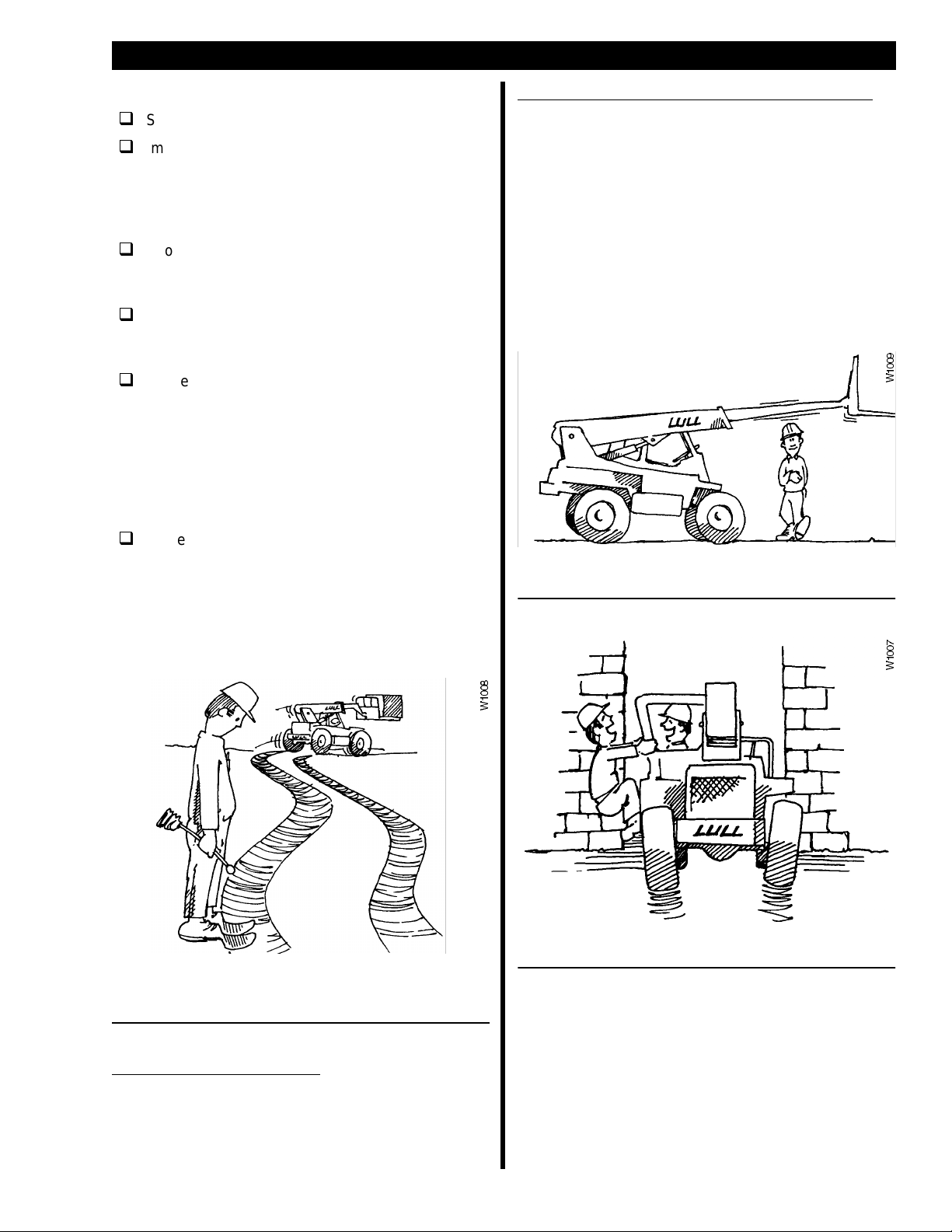
The machine is considered “attended” when the
operator is less than 25 feet from the machine and it
remains in the operat or’s view.
The machine is considered “unattended” when the
operator is 25 feet or more from the machine and the
machine is in the operator’s view, or whenever the
machine is not in the operator’s view.
Never stand or walk under a raised boom. Do not allow
others to do so.
Never operate the machine controls while you are
outside the cab. You must be properly seated in the
cab before operating any controls.
Before Leaving the Cab…
•
Bring the machine to a full stop.
•
Apply the park brake.
•
Lower the boom.
Never allow passengers on the machine.
3
Page 8
SAFETY
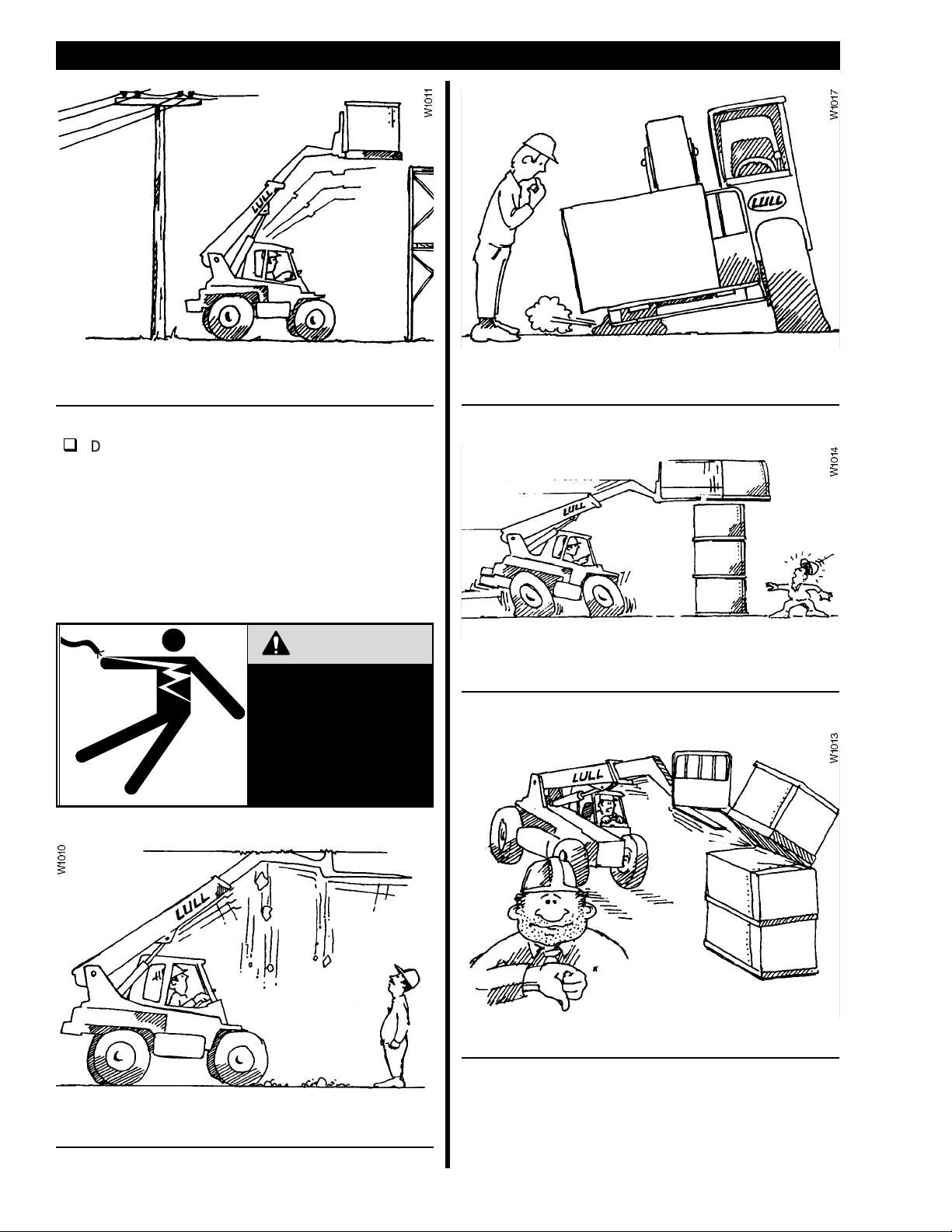
Always check clearances under power lines and
overhead structures before driving under them.
DO NOT operate the machine near energized
power lines. Always contact the electrical power
company when operating near power lines. The
lines should be moved, insulated, disconnected,
or de-energized and grounded before operating in
the area. Keep all parts of the machine at leas t 50
feet away from power lines. Contacting electrical
power lines WILL result in serious personal injury
or death!
DANGER
KEEP ALL PARTS OF
MACHINE AT LEAST 50
FEET FROM POWER
LINES. CONTACTING
ENERGIZED POWER
LINES WILL CAUSE
SERIOUS PERSONAL
INJURY OR DEATH!
Ensure that correct tire pressure and tire ballast levels
are maintained.
Never attempt to discharge a load by stopping the
forklift suddenly.
Always check for enough overheard clearance for the
boom.
4
Never lift a load using one fork.
Page 9
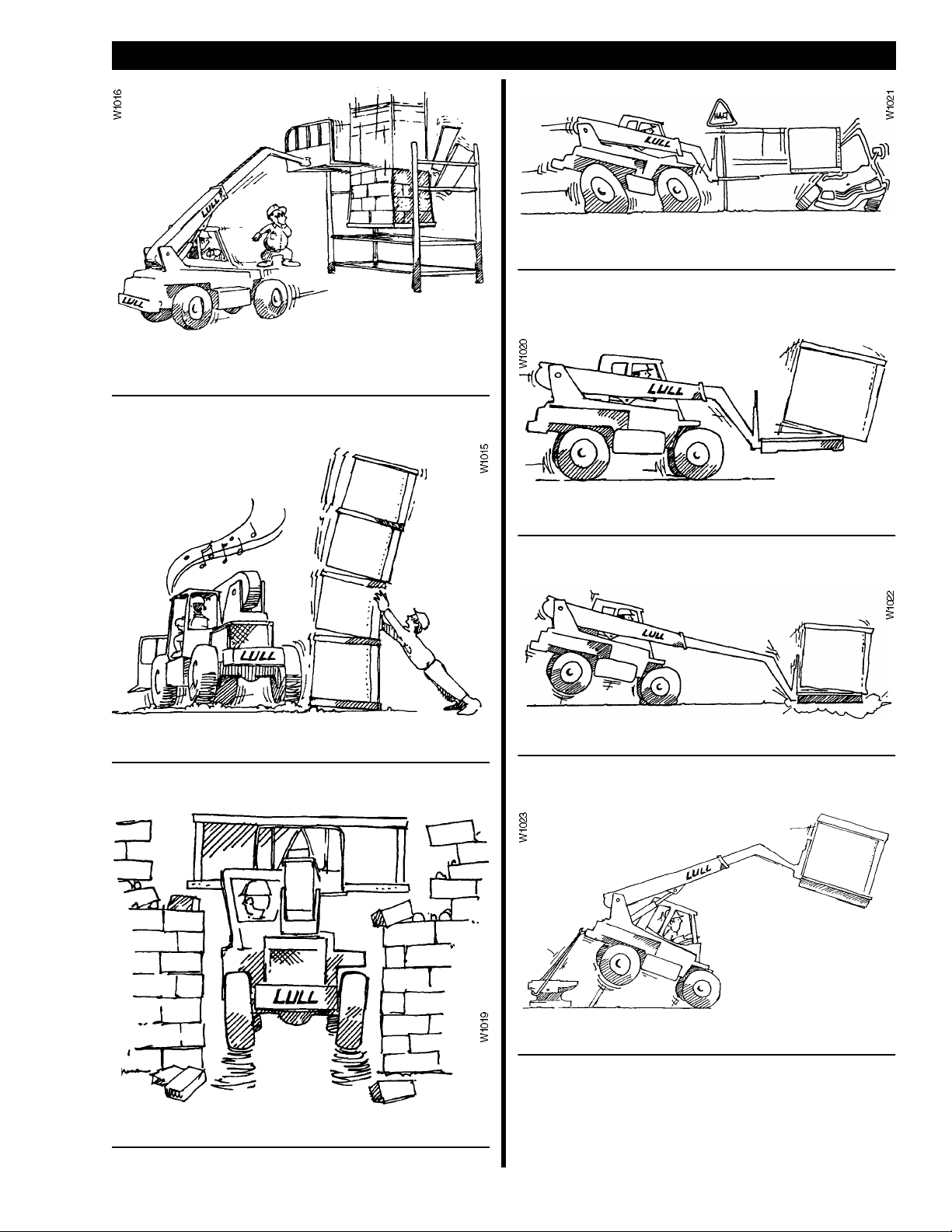
Never place loads that exceed scaffold capacity or
subject scaffold to unnecessary “shock” loads.
SAFETY
Drive carefully and avoid sudden stops and changes of
direction.
Ensure that the load is stable and secure. Check to see
that there are no loose articles that may fall off the fork.
Never stack a load on uneven ground.
Always be aware of load width.
Always check the load charts before picking up a load.
Never add unauthorized counterweights.
5
Page 10
SAFETY
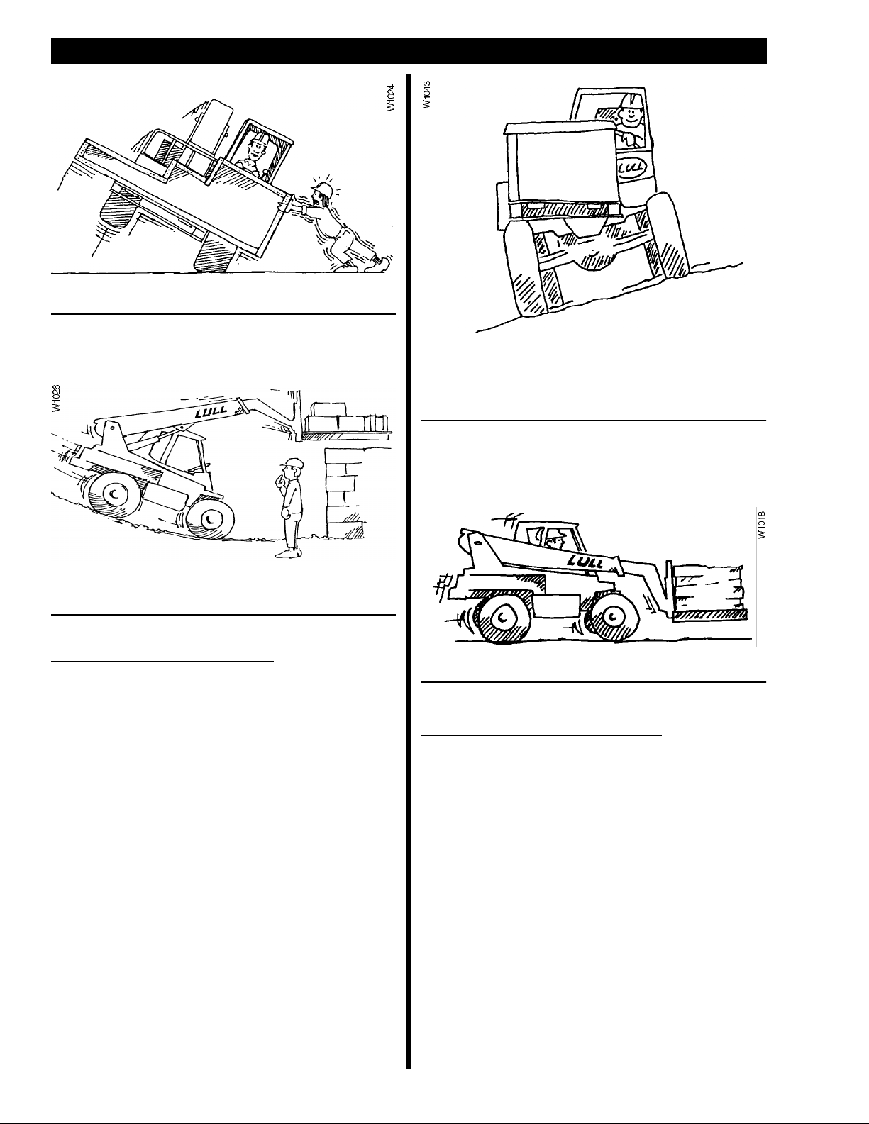
Always pick up the load at its center of gravity.
The machine can be levelled side to-side a total of
12.5° in each direction (22% grade). Any slope or
grade that exceeds this is considered excessively
steep.
Avoid parking on slopes. If it is necessary to park on a
slope, set the parking brake and block the wheels.
When Traveling On Inclines…
•
Tilt the attachment back and raised only
enough to clear the ground.
•
Avoid turning. If it cannot be avoided, turn
slowly and with ext reme caution.
•
Travel straight up and down grades.
•
When loaded and traveling up or down
grades, travel only with the load uphill.
•
When unloaded, tr avel only with the forks or
attachment downhill.
•
Proceed slowly and with extreme caution.
•
Do not travel across excessively steep
slopes.
Drive slow and carry the load as low as possible.
When Traveling on Roadways…
•
Make sure the machi ne is equipped with all
necessary lights and safety signs required
for traveling on roadways.
•
Observe all t ra ffic law s and spe e d limits.
•
Keep to the correct side of the roadway.
•
Keep a safe dist ance from other vehicles.
•
Maintain control of the machine at all times.
•
Yield the right-of-way to pedestrians and
emergency vehicles.
•
Do not pass another vehicle at intersections,
blind spots, or other dangerous locations.
•
Avoid running over loose objects and debris.
6
Page 11

Additional Safety Instructions:
•
Maneuver the machine carefully. Do not cause t he
load to shift or t he machine to tip.
•
Slow down for wet and slippery surfaces and
changes in terrain.
•
Turn the steering wheel smoothly and slow down
when turning.
•
Do not make sharp turns at high speeds.
•
Take special care when traveling without a load.
The machine is more suscept ible to tipping over on
its side.
•
Do not continue to operate the machine if an
unsafe condition i s found. Stop the machine and
report the condition to the designated authority.
•
Never make repairs or adjustments unless you are
authorized to do so.
•
Always keep your hands and feet inside the cab,
especially when in or around structures.
SAFETY
•
Never reach into the boom or attachments.
•
Understand the limitations of the machine and
drive safely.
•
Watch for pedestrians, especially when backing up
or turning and where pedestrians may step into the
path of the machine.
•
The machine may add to the overall sound level of
the work area. Give consideration to the sound
exposure of those working around you.
•
If a fuel leak is found, do not operate the machine
until the problem is fixed.
•
When approaching areas where vision is
obstructed, always slow down and sound the horn.
•
Report all accidents involving personnel, building
structures, and equipment to your supervisor or as
directed.
•
Use caution when operat ing on ramps, platforms,
trenches, and other similar surfaces.
•
Keep a clear view of the terrain and where the
machine is heading. Watch out for other vehicles,
people, and structures.
•
If the load blocks your forward view, then carefully
travel in reverse and use a signalman to guide you
if necessary.
•
Do not block access to fire lanes or fire equipment.
7
Page 12
INSTRUMENTS AND CONTROLS
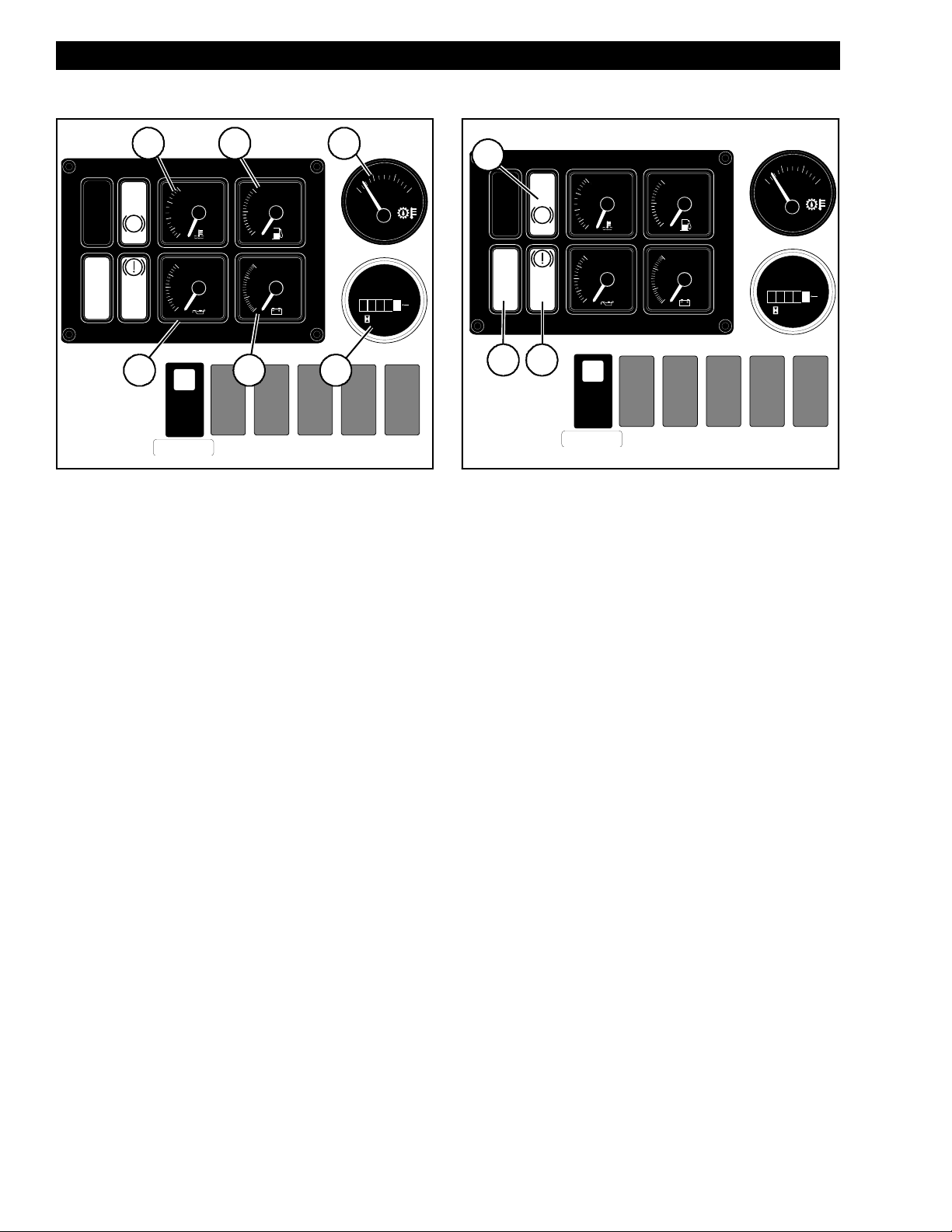
GAUGES
REAR
OSC
LOCK
P
PARK BRAKE
BRAKE
1
240
190
160
130
100
80
60
40
20
0
2
WATER FUEL
°F
OIL BATT.
psi
F
3/4
1/2
1/4
E
16
14
12
10
V
5
TRANSMISSION
DECLUTCH
Gauges
Note: Gauges and indicat or lights operate only when
the ignition switch is in the ON position.
(1)Engine Water Temperature
100 to 240 ° F. Normal operating temperature is
180 to 185 °F.
(2)
Fuel Level
(3)
Transmission Oil Temperature
from 140 to 320 °F with Celsius equivalents. If
the temperature rises above 230 °F (1 10 °C) stop
the vehicle immediately, shift to ne utral and run
the engine at half throttle. The temperature
should drop quickly. If the temperature does not
drop, shut off engine and investigate.
(4)
Engine Oil Pressu re
oil pressure. Gauge registers from 0 to 80 PSI .
Normal operating pressure is 55 to 60 PSI.
—Shows fuel level in fuel tank.
—Shows operating engine
3
°F
280
240
115
138
140
°C
160
60
TRANS
QUARTZ
0000
0
HOURS
64
H1042
—Registers fro m
—Registers
320
1
10
INDICATOR LIGHT S
1
WATER FUEL
240
190
160
130
°F
100
OIL BATT.
80
60
40
20
psi
0
TRANSMISSION
DECLUTCH
REAR
OSC
LOCK
3
P
PARK BRAKE
BRAKE
2
Indicat or Li gh t s
(1)
Park Brake
—Red lamp lights to show when park
brake is applied and goes out when park brake is
released.
(2)
Low Brake Pressure
buzzer sounds when service brake hydraulic
system pressure drops below the safe operating
level. Under normal conditions, the light and
buzzer will go out quickly aft er engine start. If the
light or buzzer does not go out or comes on
during machine operation, shut off engine
immediately, investigate, and repair before
operating. Do not operate machine when low
brake pressure light or buzzer is on.
(3)
Rear Oscillation Lock
light will come on when the boom angle i s above
40°.
F
3/4
1/2
1/4
E
16
14
12
V
10
—Red lamp lights and
—The rear oscillation lock
140
60
TRANS
0000
240
115
QUARTZ
HOURS
°F
280
138
320
°C
160
1
10
0
H1042
(5)
Voltmeter
—Indicates system voltage. Gauge
registers from 10 to 16 volts. Normal operating
voltage range is 14.5 to 15 volts. With ignition in
ON position and engine off, battery voltage is
indicated. This should normally be 12.6 volts.
(6)
Hourmeter
—
Registers total hours of machine
operation.
8
Page 13
INSTRUMENTS AND CONTROLS
H1009
H1009
IGNITION SWITCH
Ignition Swit c h Loc a tion
(1)
The ignition switch
right side.
is located on the dash, near the
Note: The starter will not engage unless the shift
selector is placed in the NEUTRAL position.
THROTTLE
1
H1007
Engine Throttle Pedal
Push throttle pedal
(1)
down to increase engine speed.
1
4
2
3
Ignition Switch Posi tions
The ignition switch has four positions:
(1)
(2)
: The key may be removed or inserted only
OFF
at this position. The engine and all electrical
circuits except the horn circuit are shut down at
this position.
: All electrical circuits except the engine
ON
starter circuit are operational.
H1021
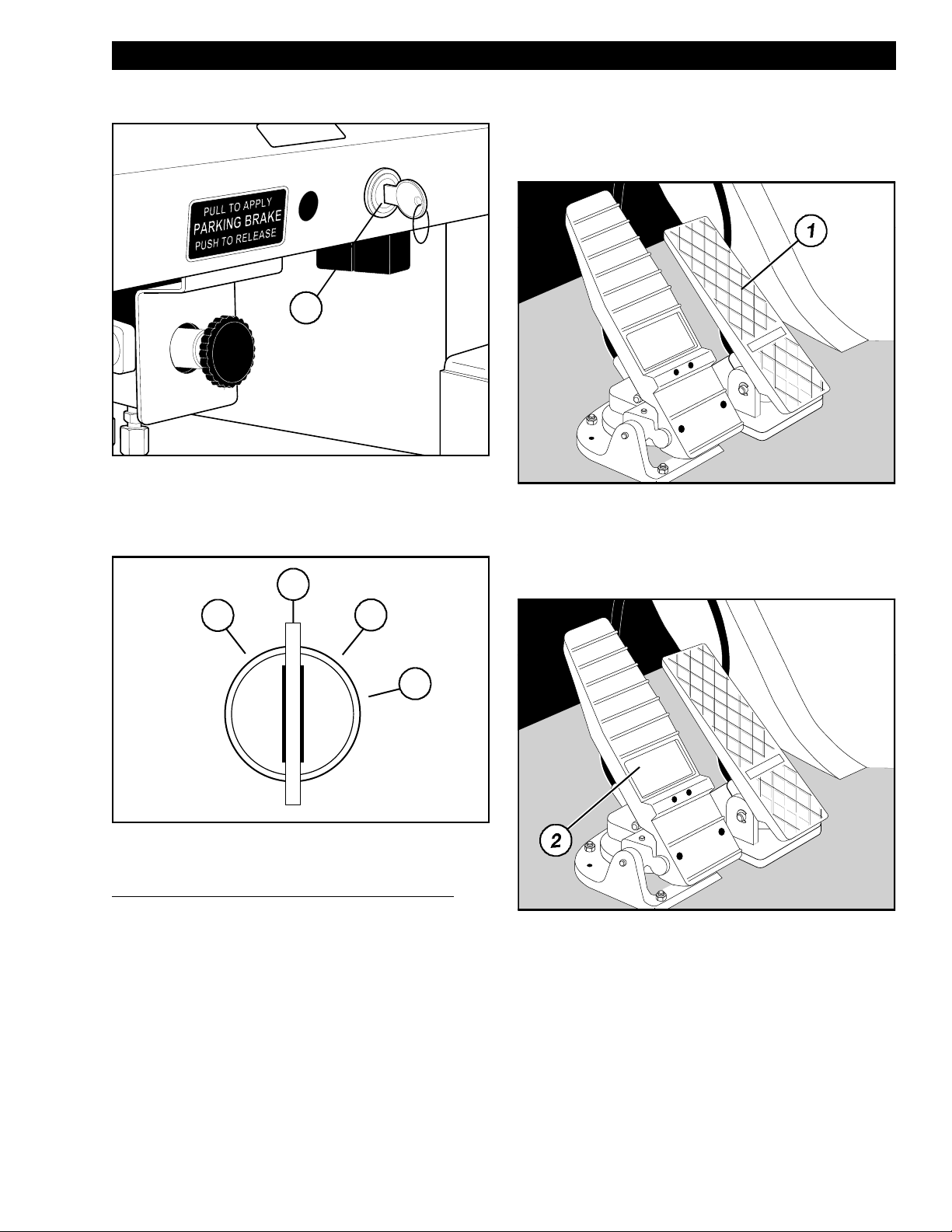
BRAKE PEDAL
Service Brak e Pedal
Push brake pedal
(2)
down to slow or stop machine.
(3)
START
key is released the switch will return to the ON
position and remain there.
(4)
This position is reserved for future use and
currently has no function.
: Activates the engine starter. When the
9
Page 14

INSTRUMENTS AND CONTROLS
PARK BRAKE CONTROL
H1007
Park Brake Control
Pull knob
Important:
(1)
out (toward you) to engage the park brake.
Always stop the machine with service
brakes before engagi ng park brake. Do
not use the park brake to slow or stop
the machine EXCEPT in an emergency.
Note: When park brake is engaged, transmission will
default to NEUTRAL, regardless of shift selector
position.
SHIFT SELECTOR
REVERSE (R): Move the lever fully rearward to select
reverse machine movement.
Speed Range Selection
The transmission has three speed ranges in forward or
reverse. To select different transmission speed ranges,
rotate the selector handle to t he desired position. Speed
ranges may be selected while the vehicle is moving in
forward or reverse.
Note: The transmission requires 3 seconds
immediately after engine start for
self-diagnostics. Always wait at least 3 seconds
after engine start before engaging transmission.
The following table shows the maximum travel speed
for each position on the selector:
ZF 3WG-100 Speeds
POSITION SPEED
1 2.5 mph
2 5.9 mph
3 13.2 mph
4(See Note)
Note: The Model 644B is not equipped with a fourth
speed. If fourth is selected, the transmission will
remain in third speed.
F
1
2
3
4
N
N
R
H1022
Shift Selector
The shift selector is located on the steering wheel
column. It controls machine travel direction and
transmission speed range.
Direction Control
Machine travel direction is controll ed by moving the shi ft
lever to one of three positions:
FORWARD (F): Move the lever fully forwar d to se lect
forward machine mo vement.
NEUTRAL (N): Move the lever to the center posi tion to
disengage the transmission. The engine may be started
only when the transmission is in NEUTRAL.
10
Page 15

INSTRUMENTS AND CONTROLS
psi
40
20
0
TRANSMISSION
DECLUTCH
H1043
1
Neutral Lock
1
2
3
4
N
F
N
R
1
ND
H1023
H1023
Neutral Lock
The shift selector is equipped with a neutral lock.
To lock the sh if t lev er in the NEUTRAL position:
1. Place the lever in the NEUTRAL position
2. Move the neutral lock lever to the (N) NEUTRAL
LOCK position.
To unlock, move the neut ral lock lever to the (D) DRIVE
position.
TRANSMISSION DECLUTCH
SWITCH
Transmission Declutch Switch
The transmission declutch switch
lighted rocker switch. Pressing the forward side of the
switch activates the transmission declutch feature when
the foot brake pedal is applied.
This feature eliminates the need to shift to NEUTRAL
before operating the hydraulic system at high engine
speeds. When the transmission is declutched, the
drivetrain is disconnected and t he hydraulic system has
full engine power.
To use the Transmission Declutch Feature:
1. The transmission must be in first or second
speed range, forward or reverse. The declutch
feature will not operate when the transmission is
in third speed range.
is an internally
(1)
2. Press the forward side of the transmission
declutch switch.
3. Press the service brake pedal or pull the park
brake knob.
4. The switch will illuminate to show the
transmission clutch has disengaged.
Press the rear si de of the switch to deactivat e the
declutch feature.
11
Page 16

INSTRUMENTS AND CONTROLS
STEER MODE SELECTOR
1
2
FRONT WHEEL STEER
3
There are three steer modes available on your machine:
1)
Oblique Ste er (Cra b S teer)
(
2)
Front Wheel Steer (2-Wheel Steer)
(
3)
Round Steer (4-Wheel Steer)
(
To select a steer mode, turn the steer mode selector so
the handle aligns with a selection on the adjac ent plate.
You will feel the sel ector slip into a detent, or “catch,”
when the desired mode is selected.
ROUND STEER OBLIQUE STEER
H1044
Steer Mode Selector
Front Wheel Steer Mode
V1002
Front Wheel Steer Mode
Front Wheel Steer mode, also known as “2-Wheel
Steer” mode, al l ows the operator to steer the machine
in a conventional manner. The front wheels of the
machine steer and the rear wheels remain in posi tion.
Use this mode when traveling on flat surf aces at hi gher
speeds. Front Wheel Steer mode should not be used in
confined and congested areas.
Important:
Synchronize (straighten and align) the
wheels before engaging Front Wheel
Steer mode.
Round Steer Mode
CAUTION
Never change steer modes while the
machine is moving. The wheels can
become misaligned and cause loss of
control.
Always stop the machine completely and synchronize
(straighten and align) the wheels before changing steer
mode. See “Synchronizing (Straightening) the Wheels”
on page 13.
V1004
Round Ste er Mo de
Round Steer mode, also known as “4-Wheel Steer”
mode, allows the front and rear wheels to steer in
opposite directions.
Use Round Steer when tight turning is required. This
mode is very useful on job sites.
12
Page 17

Oblique Steer Mode
V1010
V1011
V1012
INSTRUMENTS AND CONTROLS
V1003
Oblique Steer Mode
Oblique Steer mode, also known as “Crab Steer” mode,
enables steering of the front and rear wheels in the
same direction.
It is generally used to angle the machine in tight areas.
Oblique Steer mode moves the machine to the side
while moving forward or reverse.
Synchronizing (Straightening) the Wheels
As different steer modes are selected, it is possible for
the wheels to become misaligned. It i s also possible for
the wheels to drift out of alignment when traveling over
long distances or rough terrain.
To synchronize (straighten and align) the wheels:
1. Select ROUND steer mode.
Step 4
4. Turn the steering wheel to t he left about one turn.
5. Select ROUND steer mode.
6. Turn the steering wheel to the right until it
reaches the stop. T his makes sure the rear
wheels are fully against right stop.
7. Select FRONT WHEEL steer mode.
Step 8
Step 2
2. Turn the steering wheel to the right until it
reaches the stop.
3. Select FRONT WHEEL steer mode.
8. Turn the steering wheel to the right until it
reaches the stop.
9. Select ROUND steer mode.
V1009
Step 10
10. Turn the steering wheel to the left until wheels
are pointed straight ahead.
13
Page 18

INSTRUMENTS AND CONTROLS
V1013
Step 11
11. Drive the machine forward a short distance to
check wheel tracking.
12. S t op the machine and select the desired steer
mode.
Note: The above procedure can also be done to the
left side.
Joysticks can be moved in any direction and are not
limited to front/back, left/right movement. Moving a
joystick in a diagonal direction will cause a combination
of actions.
Front Joystick
The front joystick controls transfer carriage extension
and attachment tilt.
An auxiliary function is also available by pressing the
button on top of the handle. See “Auxiliary Joystick
Controls” on page 16 for further information.
STANDARD JOYSTICK CONTROLS
General Description — Joysticks
Joystick
Tilting Attachment Up
Pulling back on the front joystick tilts the attachment
upwards.
The joysticks control hydraulic flow to the associated
cylinders.
Control is proportional: The more joystick movement,
the greater the acti on.The speed of cylinder action is
also affected by engine/hy draulic pump speed. Action is
quicker at higher engine speeds.
14
Page 19

Tilting Attachment Down
Pushing forward on the front joystick tilts the attachm ent
downwards.
INSTRUMENTS AND CONTROLS
Retracting the Transfer Carriage
Moving the front joystick to the left retracts the transfer
carriage.
Extending the Transfer Carriage
Moving the front joystick to the right extends the transfer
carriage
Rear Joystick
The rear joystick controls boom elevation and
extension. An auxiliary function is included on the rear
joystick. This auxiliary function is reserved for future
attachment designs and is not activated on current
Model 644B machines.
Lowering the Boom
Moving the rear joystick forward lowers the boom.
15
Page 20

INSTRUMENTS AND CONTROLS
Raising the Boom
Pulling back on the rear joystick rais es the boom .
Retracting the Boom
Moving the rear joystick to the left retracts the boom.
AUXILIARY JOYSTICK CONTROLS
General Description — Auxiliary Joystick
Controls
Auxiliary Joystick Control
Extending the Bo om
Moving the rear joystick to the right extends the boom.
16
A switch is located on the top of the front joystick, under
a protective rubber cap. Pressing this switch down with
your thu mb act iv a te s t he au x iliary function.
Hold the switch down while moving the joystick left and
right. Functions for specif ic attachments are shown
below.
Releasing the switch while moving the joystick
Note:
left or right changes the function of the joystick
back to transfer carriage control.
Page 21

Tilting Carriage Control
-20
0
40
20
60
80
-20
0
20
40
60
80
DEGREES
H1045
INSTRUMENTS AND CONTROLS
Rotating Tilt Carriage to Left
Holding the button down and moving the front joystick to
the left rotates an opti onal tilting carriage to the
operator’s left.
Rotating Tilt Carri age t o Ri ght
Holding the button down and moving the front joystick to
the right rotates an optional tilting carriage to the
operator’s right.
BOOM ANGLE INDICATOR
Boom Angle Indicator
The Boom Angle I ndicator shows the angle of t he boom
relative to level ground. Use this indicator with the Boom
Extension Indicator, T ransfer Carriage Extension
Indicator, and machine Load Chart to determine correct
boom lifting capacities.
17
Page 22

INSTRUMENTS AND CONTROLS
FRAME LEVEL INDICATOR
10
5
0
Frame Level Indicato r
The Frame Level Indicator shows the lateral
(side-to-side) angle of the frame relative to level ground.
Indicator range is from 0° to 10° left or right, in
increments of one degree. When the ball is centered
(0°), the machine is laterally level. The frame tilt feature
may be used to correct machine angles up to 12.5° to
the left or right. See “Frame Tilt Control” below.
W1040
10
5
H1004
WARNING
ALWAYS LEVEL
MACHINE BEFORE
RAISING BOOM. NEVER
TILT FRAME WITH THE
BOOM RAISED.
MACHINE MAY TIP AND
CAUSE SERIOUS
PERSONAL INJURY OR
DEATH!
(1)
The control lever
prevent unintentional operation. Lift the lock ring
is equipped with a safety lock to
(2)
to
unlock the lever and allow it to be moved left or ri ght.
Return the control l ever to center position and release
lock ring to secure lever.
The lever can be moved either left or right, tilting the
frame accordingly. To level the f rame, move the lever in
the direction you want the ball in the frame level
indicator to move.
FRAME TILT CONTROL
1
2
H1005
Frame Tilt Control
The frame t ilt cont r ol is u se d to le v el the machine
laterally (side-to-side) up to 12.5°, left or right. The
lateral angle of the machine, relative to level ground, is
shown on the frame level indicator (see “Frame Level
Indicator” above). The control is functional only while
the engine is running.
18
Page 23

CHECK THE EQUIPMENT
KEEP ALL PARTS OF
MACHINE AT LEAST 50
FEET FROM POWER
LINES. CONTACTING
ENERGIZED POWER
LINES WILL CAUSE
SERIOUS PERSONAL
INJURY OR DEATH!
DANGER
Note: Before you begin your workday, take time to
)
check
good operational condition.
your forklift a nd have all syst e ms in
9
(
BEFORE OPERATING THE MACHINE
9
Remove or put away tools, lunch buckets, chains,
hooks or any other loose objects that could
interfere with operation.
KNOW THE WORK AREA
Check the following:
9
Warning decals, special instructions and operators
manuals. Make sure they are legible and stored in
the proper location. NEVER operate without a
legible load chart.
9
Engine oil level. Add oil as required.
9
Radiator coolant level. Add coolant as required.
9
Hydraulic fluid level. Add hydraulic fluid as
required.
9
Hydraulic hoses and hose connections for wear or
leaks. Repair or replace any damaged hoses or
connections.
9
Transmission oil cooler and engine radiator for dirty
fins.
9
Back-up alarm and horn.
9
Forks for welded repairs, cracks, wear and
misalignment.
WARNING
Never repair forks by welding. Never use
forks with welded repairs. Forks may break
and falling load or forks may cause serious
injury or death.
9
Tires for cuts, bulges, correct tire pressure and
proper ballast content.
9
All wheel lugs.
9
Service and park brakes for proper operation.
9
All instruments, gauges and indicator lights.
9
The steering, left and right.
9
All control levers for proper operation.
9
Keep engine and radiat or clean and free of dirt and
flammable material.
9
The condition and operation of the seat belt and its
mounts.
9
Steps, pedals, and non-ski d surfaces. Make sure
they are clean and free of dirt, grease, oil, snow
and ice.
9
Placement and operation of doors, guards and
covers.
9
Cleanliness and operation of mirrors, window
wipers and work lights.
Note: If there is any indication that faulty equipment
exists, shutdown safely, inform the proper
authority and DO NOT operate the forklift until
the problem has been fixed.
Learn as much as poss ible about the work area before
operation. Walk around the worksite and inspect the
terrain th a t yo u w ill be tra ve lling on.
Make a not e of surfaces to be avoided, including…
•
Holes & Drop-offs.
•
Obstacles.
•
Soft mud & standing water.
•
Oil spills & slippery surfaces.
Note: I f any of the above conditions exist in the work
area, correct the condition before operating. If
the condition cannot be corrected, avoid
operation in the problem area.
When operating on docks, ramps or floors, check for
weak spots. Clear away trash and debris. Pick up
anything that could puncture a tire. When required,
check the forklift's maximum fully loaded ground
pressure weight if operating on a hollow floor system.
Watch for condit ions that could cause…
•
Loss of control.
•
A collision.
•
Tipover.
Check overhead clearances. Know the size of
doorways and canopies. Know exactly how much
clearance you have under power lines and telephone
lines.
All local, state/provincial and federal regulations must
be met before approaching power lines, overhead or
underground cables or other power sources with any
part of your forklift. Do not operate the machine near
energized power lines. Always contact the electrical
power company when operating near power lines. The
lines should be moved, insulated, disconnected, or
de-energized and grounded before operating in the
area. Keep all parts of the machine at least 50 feet away
from power lines.
19
Page 24

BEFORE OPERATING THE MACHINE
PLAN YOUR WORK
Before you operate, know how and where you will
travel, turn and pickup, lift and place loads.
Choose a smooth level route to prevent possible tipover
or loss of load.
If possible, avoid cro ssi n g…
•
Ruts.
•
Ditches.
•
Curbs.
•
Exposed railroad tracks.
Note: When these conditions cannot be avoided, keep
the load as low as possible and travel very
slowly and with extreme caution.
Know where there are any blind corner conditions on
the worksite. Before t urning a blind corner, stop, sound
your horn, and proceed slowly.
Always maintain safe dist ances between your forklift
and other equipment that may be on the worksit e.
Know the weights of all loads you may be expected to
transport before attempting to lift them. Avoid loads of
loose material if possible. Check that loads ar e properly
banded or strapped together.
If you will be placing l oads at high elevations, remember
your depth perception is decreased because of
distance. Use a signal person near the point where the
load is to be landed.
Insure that adequate clearance is provided between
both rear tail swing and front fork swing of the forklift to
avoid injury to personnel or damage to nearby
equipment.
An operator must not use drugs or alcohol which can
affect his alertness and coordination. An operator on
prescription or over-the-counter drugs needs medical
approval to safely operate these machines.
KNOW THE RULES
Most employers have rul es governing proper operation
and maintenance of equipment. Before you start work at
a new location, check with your supervisor or the safety
coordinator. Ask about rules you may be expected to
obey.
Make sure you understand the rules covering traf fic at
your jobsite. Make sure you recognize and understand
the meaning of all signs, flags, and markings. Make
sure you understand all hand, flag, whistl e, siren, or bell
signals. Make sure you know when to use lights, turn
signals, flashers and horn.
PROTECT YOURSELF
Wear all the protective clothing and personal saf ety
devices issued to you or called for by job conditions.
You may need:
•
A hard hat.
•
Safety shoes.
•
Safety glasses, goggles, or face shield.
•
Heavy gloves.
•
Hearing protection.
•
Reflective clothing.
Know where you will be expect ed to park your forklift at
the end of the work day, preferably in a level area out of
traffic. If the area i s on a slope or incline, posi tion the
forklift at right angles to the slope, set the parking brake,
lower the boom to the ground, and block the wheels.
Remember…
•
Be alert - know that conditions can change.
•
Use common sense - show that you are a
responsible operator.
•
Be a defensive operat or - prevent accidents before
they happen.
SAFE MACHINE OPERATION
For safe operation of this rough terrain forklift you must
be a qualified and authorized operator. To be qualified,
you must understand the written instructions supplied
by the manufacturer, have training (including actual
operation of this m achine) and know the safety rules
and regulations for the jobsite.
20
•
Wet weather gear.
•
Respirator or filter mask.
MOUNT AND DISMOUNT
PROPERLY
Always use “Three Point Contact” when mounting or
dismounting the machine. “Three Point Contact” means
that three out of four arms and legs are in contact with
the machine at all times during mount and dismount.
Clean your shoes and wipe y our hands before mount ing
machine. Always use hand-hold and step when
mounting.
Never use control levers as a hand-hold when mounting
or dismounting the machine. Never step on foot controls
when mounting or dismounting the machine.
Never attempt to mount a moving machine.
Page 25

GENERAL OPERATING PROCEDURES
CAUTION
STARTING PROCEDURES
Before operating, walk completely around the machine.
Make certain no one is under it, on it or cl ose to it. Let
all other workers and bystanders know you are
preparing to start the machine.
until everyone is clear.
DO NOT
To start engine...
1. Be properly seated.
2. Set park brake.
3. Move shift selector to NEUTRAL positio n. Place
the neutral lock lever to NEUTRAL LOCK
position.
4. Apply brakes.
5. Turn ignitio n switch clockw ise, cranking the
engine. (Do not crank the engine longer than 20
seconds. Wait 2 minutes to allow starter to cool
down before trying again.)
6. Allow engine to warm up.
The transmission requires 3 seconds
Note:
immediately after engine start for
self-diagnostics. Always wait at least 3 seconds
after engine start before engaging transmission.
7. In cold weather operation, progressively move
each function a small distance back and forth
until full cycle has been accomplished.
start machine
SHUTDOWN PROCEDURES
Correct shutdown is important to the safe operation of
the machine.
Always follow these steps:
1. Come to a full stop.
2. Set the park brake.
3. Lower boom to the ground.
operator’s compartment while the machine is
supporting a load.
4. Place transmission shift selector in NEUTRAL
position. Place the neutral lock lever to
NEUTRAL LOCK position.
5. Idle engine for 1–3 minutes for gradual cooling.
This is especially important for turbocharged
engines.
6. Shut off engine.
7. After the engine is shut off, move all hydraulic
levers. If any machine movement is detected, a
problem
be advised immediately.
machine into service until the problem has been
fixed.
8. Remove ignition key.
9. Lock anti-vandalism covers and closures.
10. Dismount.
exist and your supervisor should
MAY
DO NOT
DO NOT
leave the
put the
To make sure warm oil reaches the rear carriage
tilt cylinders, slowly raise and lower the boom
several times. Failure to cycle the rear carriage
tilt cylinders during cold machine start-up can
damage the cylinders and structure.
8. Level machine, move frame tilt full to the right,
then full to the left, then back to level.
9. Raise boom full up and full down. Extend inner
boom full out and retract full in.
10. Tilt attachment full down and full back.
1 1. Move transfer carriage ful l forward and full back.
It is your responsibility to evaluate working
Note:
conditions and adjust your operation of the
forklift accordingly.
1 1. Block wheels if on a slope or incline.
TRAVEL I NG
When traveling over rough terrain, soft
ground, or wet/ icy surfaces, slow dow n and
shift to a lower gear.
Travel only at speeds that permit stopping
in a safe manner.
When traveling, keep forks as low as
possible while maintaining safe clearance
with the ground.
Start and stop machine to check brakes.
Check park brake by holding on hill.
Check the three steering modes:
Round
Front Wheel
Oblique
21
Page 26

GENERAL OPERATING PROCEDURES
FOLLOW SAF E OPERATING
PROCEDURES
WARNING
ALWAYS LEVEL
MACHINE BEFORE
RAISING BOOM. NEVER
TILT FRAME WITH THE
BOOM RAISED.
MACHINE MAY TIP AND
CAUSE SERIOUS
PERSONAL INJURY OR
DEATH!
ALWAYS
machine before lifting a load. Lift only within the
capacity of the machine as shown by the load
chart.
Never tilt the frame when the boom is raised.
Operate the controls smoothly–don't jerk the
hydraulic controls or steering wheel.
Avoid sudden stops, starts, turns or changes in
direction.
Never “cowboy” or play games with a forklift.
check the load chart mounted in the
REAR OSCILLATION LOCK SYSTEM
The Rear Oscillation Lock System provides safety and
stability by prevent i ng the frame from rotating on the
rear axle.
The rear oscillation lock will be operational when any or
all of the following conditions apply:
1. When the boom angle exceeds 40°.
2. When the service brakes are applied.
3. If a system component fails.
When the boom angle is above 40°, the following
conditions apply:
1. Rear axle cylinder locks, preventing the frame
from rotating on the rear axle.
2. Transmission is disengaged.
3. Frame tilt function is disengaged.
Note: When the frame tilt function is disengaged, it
CANNOT be overridden by the operator unless
the boom angle is below 40°.
When the service brakes are depressed, the following
conditions apply:
Operate machine controls only while seated in the
operator's compartment.
Never leave the operator's seat without first
lowering the boom to the ground, setting the park
brake, and placing transmission in NEUTRAL.
WARNING
Keep all parts of your body inside the
operators compa rtme nt while oper ating the
rough terrain forklift.
DO NOT
boom, lift mechanism or transfer carriage areas.
DO NOT
the boom, lift mechanism or transfer carriage.
STAY ALE RT!
loose, or fail to operate on your machine, stop
work, shut down the machine and alert your
supervisor immediately.
touch, lean on, or reach through the
permit others to do so. Never climb on
Should something break, come
1. Rear axle cylinder locks preventing the frame
from rotating on the rear axle.
2. The rear oscillation lock cylinder can be unlocked
by the frame tilt function when the boom is below
40 °.
WARNING
ALWAYS LEVEL
MACHINE BEFORE
RAISING BOOM. NEVER
TILT FRAME WITH THE
BOOM RAISED.
MACHINE MAY TIP AND
CAUSE SERIOUS
PERSONAL INJURY OR
DEATH!
Lower the boom or release the service brake to
deactivate the rear oscillation lock system. If the system
does not deact ivate, a problem exists and must be
investigated.
22
Page 27

LIFT THE LOAD SAFELY
WARNING
GENERAL OPERATING PROCEDURES
Important:
1. If possible, plan to load, unload and turn on flat
level ground. If not level, use frame tilt (See
“Frame Tilt Control” on page 18) to level
machine. Level indicator
sure there is enough cl earance overhead and all
around for lifting and traveling. Watch the front
and rear clearances when turning.
2. If loads are to be handled several times, place
stacking blocks under l oads.
3. For sideshift equipped forklifts, center the forks
and carriage before lifting.
4. Inspect load to be lifted. Approach the load
slowly and squarely wi th fork tips straight and
level. Ad jus t pa llet for k s as ne ce s s ar y.
5. Engage the load by moving the transfer carriage
slowly forward until the load touches the fork
carriage backrest.
6. Tilt the forks back to position the load for travel,
then lift the load only enough to clear obstacles.
7. Fully retract the transfer carriage.
ALWAYS
in the machine before lifting a load. Lift
only within the capacity of the machine
as shown by the load chart.
check the load chart mounted
be centered. Be
MUST
TRANSPORT THE LOAD SAFELY
When transporting the load…
Keep the forks ti lted back with boom retract ed and
the load close to the ground.
When traveling over inclines, slopes or
ramps
…
Tilt the attachment back and raised only
enough to clear the ground.
Avoid turnin g. If it cannot be avoided, tu rn
slowly and with extreme caution.
Travel straight up and down the grades.
When loaded and traveling up or down
grades, travel with the load uphill.
When unloaded, tr avel only with the fo rks
or attachment downhill.
Proceed slowly and wit h ext reme cau t ion.
Do not travel across excessively steep
slopes or unstable surfaces.
Failure to follow these instructions may
result in serio us personal in jury or deat h.
Reduce speed and sound horn at blind
intersections, exits and when approaching
pedestrians.
Slow down for turns, ramps, dips, uneven or
slippery surfaces and in congested areas.
Avoid driving over loose objects and holes in
roadway surfaces to prevent losing the load or
tipping the machine.
Keep the load as low as possible. Never carry the
load above eye level.
Where the load will obst ruct the operator's visi on,
it is recommended that the forklift be operated i n
REVERSE
travel. Travel at a slower speed and get someone
to direct you.
Avoid excessively steep slopes or unstable
surfaces.
machine, keep the load low and proceed with
extreme caution.
circumstances, drive across excessive ly steep
slopes.
The machine can be levelled side -to-side a total
of 12.5° in each direction (22% grade). Any slope
or grade that exceeds this is considered
excessively steep.
If a slope is too steep to allow the frame to be
leveled, do not raise the boom. The frame must
always be level before raising the boom.
, looking backwards in the direction of
If you must drive on a slope, level the
DO NOT
, under any
23
Page 28

GENERAL OPERATING PROCEDURES
Avoid crossing ditches, curbs or exposed railroad
tracks. If crossing cannot be avoided, keep the
load as low as possible, travel very slowly, and
proceed with cauti on.
Avoid panic braking. Apply brakes smoothly for a
controlled stop to prevent toppling the load.
SAFELY PLACING THE LO AD
Elevated or Overhead Placement
Important:
When stacking or placing a load to a
high landing use extreme caution! There
may be other workers in the immediate
area you cannot see. Make sure that all
bystanders are away from the area
where the load could tip or fall.
W1042
4. Level the machine using frame tilt
load is raised. (See “Frame Tilt Control” on page
18)
DO NOT
forks are tilted to one side. If the forklift cannot be
positioned so the l oad is level before lifting,
reposition the forklift. The likelihood for forklift
tipover is greatly increased if the load is not level
before lifting.
raise the load for placement if the
BEFORE
WARNING
ALWAYS LEVEL
MACHINE BEFORE
RAISING BOOM. NEVER
TILT FRAME WITH THE
BOOM RAISED.
MACHINE MAY TIP AND
CAUSE SERIOUS
PERSONAL INJURY OR
DEATH!
5. Slowly and carefully raise the load. I f there is any
indication of instability during the lift (i.e.
movement, leaning, swaying), stop immediately,
lower the load, move the forklift to a more stable,
level position. As lift height increases, your depth
perception decreases. Placing the load safely at
a high elevation may require a signalman to
guide you.
6. When the load is slightly higher than the landing
point,
SLOWLY
.
stop the lift.
the
1. Be sure the landing point can safely support the
weight of the l oad. The chosen landing location
should be level , both front-to-back and
side-to-side.
You should know or be able to estimate the
weight and load center of the load that you will
be lifting. If you are unsure of the weight and load
center of the load, check with your supervisor or
with the supplier of the material.
the load chart mounted in the machine before
lifting a load. Lift only within the capacity of the
machine as shown by the load chart.
2. Drive as close as possible to the landing
location. Approach very slowly with the load as
low as possible.
3. Tilt carriage rearward to cradle the load.
ALWA YS
check
WARNING
Do not ram the hydraulic lift cylinder to the
end of its stroke. The jolt could spill the lo ad
resulting in serious person al injury or death.
24
Page 29

7. Use the transfer carriage to place the load
directly over the landing point. The transfer
carriage allows safe and easy placement of the
load without moving the machine. (Consult load
charts for transfer capacity.) Forks should be
level and parallel to the landing surface so that
they may be easily retracted from under the load.
Before retracting the forks, check landing point
for any excessive bowing, cracking noises or
other indications of overloading.
.
GENERAL OPERATING PROCEDURES
If there is any indication that the landing surface
cannot handle the weight of the load, place the
load at a different location that you know can
handle the weight. If the landing surface cannot
handle the weight of the load, pick the load back
up, lower it to the ground and lift a lighter load.
8. Lower the load slowly to place it and relieve the
weight from the forks. Retract the transfer
carriage until the forks are clear of the load.
Lower and retract the boom
the machine.
9. The forklift can now be moved from the landing
location to continue work.
BEFORE
moving
LIFTIN G PERSONNEL
LULL
the rough terrain forklift as a personnel lift. It is designed
for material handling ONLY. If personnel MUST be
lifted, lift only in accordance with ASME/ANSI B56.6
1992 , Para. 5.15 and with a properly designed work
platform.
®
strongly recommends that you DO NOT use
25
Page 30

FLUID & LUBRICANT SPECIFICATIONS
GENERAL FLUID AND LUBRICANT
SPECIFICATIONS
General Fluid & Lubricant Specifications
System or
Component
Fuel System
Hydra u lic
System
Engine Cooling
System
Engine Oil
Transmission See “Transmission Oil
Differential
(Front & Rear)
Planetary Hub Use 58 oz. SAE 90 API GL-5 and 4
1
1
1
Fluid or
Lubrica nt
See “Fuel Requirements”
Heavy Duty
Hydraulic Fluid
Ethylene Glycol/
Pure Water Mix
with additives.
See “Engine Oil Specifications”
Specifications”
Gear Lubricant SAE 90 API GL-5
oz. Friction Modifier, LULL
Specification
Amoco Rykon
MV or equiv.
Low silicate
Ethylene Glycol
ASTM D5345
ASTM D4985
®
P26720
ENGINE OIL SPECIFICATIONS
John Deere Engines
Use the table below to select the oil viscosit y based on
expected air temperature range during the period
between oil changes. Consult the John Deere
Operator’s Manual for additional information.
New John Deere engines use special break-in oil
Note:
for the initial period of operation. Consult engine
Operator’s Manual for additional information.
Engine Oil Selection Chart, John Deere
Engine Oil, John Deere
Oil Grade
SAE 5W-30 -22 to +86 °F -30 to + 30 °C
SAE 10W-30 -4 to +86 °F -20 to +30 °C
SAE 15W-40 +5 to 122 °F -15 to 50 °C
SAE 30W +32 to +86 °F 0 to +30 °C
SAE 40W +50 to +104 °F +10 to +40 °C
Arctic Oil (e.g.
MIL-L-46167B)
Approved Engine Oil Specifications
Temperature
Range °F
Below -22 °F Below -30 °C
Temperature
Range °C
Grease Points Grease Lithium-based
1. Consult engine manufacturer’s Operator’s
Manual for additional information.
API CD/ CE
CCMC Specification D4, D5
SAE 5W-30
SAE 10W-30
SAE 15W-40
SAE 30W
SAE 40W
MIL-L-46167B
26
Page 31

FLUID & LUBRICANT SPECIFICATION S
TRANSMISSION OIL
SPECIFICATIONS
The following table shows approved lubricants and
associated temperature ranges for use with ZF 3WG
and 4WG series transmissions.
Transmission Oil Selection Chart
ZF 3WG-100 & 4WG-100 Transmissions
Min. Oil
Oil Grade
Temperatu re
for Starting
Engine
Engine Oils
SAE 20W-20 +14 °F (-10 °C) +41 °F (+5 °C)
SAE 15W-40 +5 °F (-15 °C) +32 °F (0 °C)
SAE 10W,
10W-30,
10W-40
Automatic Transmission Fluid (ATF)
ATF -22 °F (-30 °C) +14 °F (-10 °C)
Approved Lubricants (Engine Oils)
API CD/ CE/ CF/ SF/ SG
MIL-L-2104 C/ D/ E
MIL-L-46152 C/ D/ E
SAE 10W
SAE 10W-30
SAE 10W-40
SAE 15W-40
SAE 20W-20
-4 °F (-20 °C) +23 °F (-5 °C)
Min. Oil
Temperature
for Engaging
Transmission
FUEL REQUIREMENTS
General
Diesel fuels are blended to meet the local temperature
requirements. The standard grades are:
1. 1D for temperatures -22 to +86 °F
(-30 to +30 °C).
2. 2D for temperatures +14 to +122 °F
(-10 to +50 °C)
There are two main classifications of diesel fuel in
general use:
1. Low-sulphur, “on-highway” diesel fuel.
2. Medium-sulfur, “off -highway” diesel fuel. This fuel
contains blue dye.
The engine manufacturer specifies the diesel fuel
requirements. Additional information can be found
below and in the engine manufacturer’s Operator’s
Manual.
Consult your local fuel distributor for the properties of
the diesel fuels available in your area.
John Deere Engines
Use of regular-sulfur “off-highway” diesel fuel is
recommended.
If low-sulfur “on-highway” diesel fuel is used, John
Deere Diesel Fuel Conditioner (TY22030) must be
added.
Use of low-sulfur fuel without the specified conditioner
may cause premature fai lure of the engine’s f uel system
components and void the warranty.
Automatic Trans mission Fluid (A TF) may on ly be used
at ambient temperatures below +14 °F (-10 °C)
27
Page 32

SERVICE/LUBRICATION SCHEDULE MODEL 644B-37
22 23242423 22 22 22
79
19
12
19 19
6
17
16
20
22 2324
252423 22
8
15 10
2222
12
1115 16 16
R1014
2821
14
28
16
13
26
2028
25
8
18
26
27
26
3
54
27
13
26
21
18
2
1
R1015
Page 33

SERVICE/LUBRICATION SCHEDULE MODEL 644B-37
SYSTEM CAPACITIES AND PRESSURES
HYDRAULIC SYSTEM & RESERVOIR 65 GALS PLANETARY HUB (EACH) 62 OZ (SEE NOTE 1)
FUEL TANK 40 GALS ACCUMULATOR (NITROGEN PRECHARGE) 400–425 PSI
COOLING SYSTEM 18 QTS TIRES — 13.00 X 24 PER TIRE
ENGINE CRANKCASE — JOHN DEERE 14 QTS PRESSURE 55 PSI
TRANSMISSION — DRAIN/REFILL (APPROX.) 11 QTS SODIUM CHLORIDE 115 LBS
DIFFERENTIAL 13 QTS WATER 33 GALS
HOURS OF OPERATION
# DESCRIPTION DAILY WEEKLY 20 50 100 200 500 1000 2000 REMARKS
1 ENGINE OIL C *CF CF SEE ENGINE MANUAL
2 ENGINE OIL FILTER *R R SEE PARTS BOOK
3 FUEL FILTER/WATER SEP. C R SEE PARTS BOOK
4 TRANSMISSION FLUID C *CF CF SEE OTHER SIDE OF CARD
5 TRANSMISSION FILTER *R R SEE PARTS BOOK
6 HYD. RESERVOIR FLUID C CF SEE OTHER SIDE OF CARD
7 HYD. RETURN FILTER C *R R SEE PARTS BOOK
8 HYD. PRESSURE FILTER C *R R SEE PARTS BOOK
9 HYD. TANK BREATHER CLN R SEE PARTS BOOK
10 AIR CLEANER C CLN R SEE PARTS BOOK
11 ENGINE COOLANT C CF SEE OTHER SIDE OF CARD
12 AXLE DIFFERENTIAL *CF C CF SAE 90 API-GL-5 LUBE
13 PLANETARY HUBS *CF C CF SEE NOTE 1
14 BOOM PIVOT LUBE 2 GREASE FITTINGS
15 HOIST PIVOTS LUBE 4 GREASE FITTINGS
16 TILT CYLINDER PIVO TS LUBE 6 GREASE FITTINGS
17 QUICK ATTACH PIV OT LUBE 1 GREASE FITTINGS
18 TRANSFER ROLLERS LUBE 4 GREASE FITTINGS
19 OSCILLATION PIVOTS LUBE 4 GREASE FITTINGS
20 FRAME TILT CYLINDER LUBE 2 GREASE FITTINGS
21 REAR AXLE LOCK CYLINDER LUBE 2 GREASE FITTINGS
22 STEER CYLINDERS LUBE 8 GREASE FITTINGS
23 STEER SPINDLES LUBE 8 GREASE FITTINGS
24 TIE ROD ENDS LUBE 4 GREASE FITTINGS
25 PARK BRAKE BELLCRANK LUBE 1 GREASE FITTINGS
26 DRIV E SHAFT U-JOINTS LUBE 4 GREASE FITTINGS
27 DRIVE SHAFT S LIP YOK ES LUBE 2 GREASE FITTINGS
28 BOOM PADS LUBE 2 FITTINGS + SLIDES
NOTES:
1) USE 58 OZ. SAE 90 API GL-5 & 4 OZ. FRICTION MODIFIER, LULL
®
P26720.
* FIRST HOURS OF OPERATION
C= CHECK, SERVICE AS NECESSARY
CF= CHANGE FLUID
R= REPLACE
CLN= CLEAN CAREFULLY
SHORTEN SERVICE INTERVALS
ACCORDINGLY WHEN OPERATING
UNDER DUSTY OR SEVERE
CONDITIONS.
INSPECT ALL FLUID SYSTEMS AND
CHANGE FLUID WHEN FLUID SHOWS
TRACES OF CONTAMINATION OR HIGH
TEMPERATURES, EVIDENCED BY
STRONG ODOR, DISCOLORATION, OR
SEPARATION.
R1013
29
Page 34

SERVICE/LUBRICATION SCHEDULE MODEL 644B-42
22 23242423 22 22 22
79
19
12
19 19
6
17
16
16
20
20
13
26
22 2324
252423 22
8
28
25
8
18
26
15 10
26
2222
13
3
12
1115 16 16
21
1
R1020
2821
14
18
2
30
27
26
27
54
R1021
Page 35

SERVICE/LUBRICATION SCHEDULE MODEL 644B-42
SYSTEM CAPACITIES AND PRESSURES
HYDRAULIC SYSTEM & RESERVOIR 65 GALS PLANETARY HUB (EACH) 62 OZ (SEE NOTE 1)
FUEL TANK 40 GALS ACCUMULATOR (NITROGEN PRECHARGE) 400–425 PSI
COOLING SYSTEM 18 QTS TIRES — 13.00 X 24 PER TIRE
ENGINE CRANKCASE — JOHN DEERE 14 QTS PRESSURE 55 PSI
TRANSMISSION — DRAIN/REFILL (APPROX.) 11 QTS SODIUM CHLORIDE 115 LBS
DIFFERENTIAL 13 QTS WATER 33 GALS
HOURS OF OPERATION
# DESCRIPTION DAILY WEEKLY 20 50 100 200 500 1000 2000 REMARKS
1 ENGINE OIL C *CF CF SEE ENGINE MANUAL
2 ENGINE OIL FILTER *R R SEE PARTS BOOK
3 FUEL FILTER/WATER SEP. C R SEE PARTS BOOK
4 TRANSMISSION FLUID C *CF CF SEE OTHER SIDE OF CARD
5 TRANSMISSION FILTER *R R SEE PARTS BOOK
6 HYD. RESERVOIR FLUID C CF SEE OTHER SIDE OF CARD
7 HYD. RETURN FILTER C *R R SEE PARTS BOOK
8 HYD. PRESSURE FILTER C *R R SEE PARTS BOOK
9 HYD. TANK BREATHER CLN R SEE PARTS BOOK
10 AIR CLEANER C CLN R SEE PARTS BOOK
11 ENGINE COOLANT C CF SEE OTHER SIDE OF CARD
12 AXLE DIFFERENTIAL *CF C CF SAE 90 API-GL-5 LUBE
13 PLANETARY HUBS *CF C CF SEE NOTE 1
14 BOOM PIVOT LUBE 2 GREASE FITTINGS
15 HOIST PIVOTS LUBE 4 GREASE FITTINGS
16 TILT CYLINDER PIVO TS LUBE 6 GREASE FITTINGS
17 QUICK ATTACH PIV OT LUBE 1 GREASE FITTINGS
18 TRANSFER ROLLERS LUBE 4 GREASE FITTINGS
19 OSCILLATION PIVOTS LUBE 4 GREASE FITTINGS
20 FRAME TILT CYLINDER LUBE 2 GREASE FITTINGS
21 REAR AXLE LOCK CYLINDER LUBE 2 GREASE FITTINGS
22 STEER CYLINDERS LUBE 8 GREASE FITTINGS
23 STEER SPINDLES LUBE 8 GREASE FITTINGS
24 TIE ROD ENDS LUBE 4 GREASE FITTINGS
25 PARK BRAKE BELLCRANK LUBE 1 GREASE FITTINGS
26 DRIV E SHAFT U-JOINTS LUBE 4 GREASE FITTINGS
27 DRIVE SHAFT S LIP YOK ES LUBE 2 GREASE FITTINGS
28 BOOM PADS LUBE 4 FITTINGS + SLIDES
NOTES:
1) USE 58 OZ. SAE 90 API GL-5 & 4 OZ. FRICTION MODIFIER, LULL
®
P26720.
* FIRST HOURS OF OPERATION
C= CHECK, SERVICE AS NECESSARY
CF= CHANGE FLUID
R= REPLACE
CLN= CLEAN CAREFULLY
SHORTEN SERVICE INTERVALS
ACCORDINGLY WHEN OPERATING
UNDER DUSTY OR SEVERE
CONDITIONS.
INSPECT ALL FLUID SYSTEMS AND
CHANGE FLUID WHEN FLUID SHOWS
TRACES OF CONTAMINATION OR HIGH
TEMPERATURES, EVIDENCED BY
STRONG ODOR, DISCOLORATION, OR
SEPARATION.
R1019
31
Page 36

SAMPLE LOAD CHART
40
12
INDICATES REAR
11
10
35
30
9
8
25
7
20
6
OSCILLATION LOCK
ENGAGED
TRANSACTION
80" (203 CM)
50°
60°
70°
MAXIMUM BOOM LOAD CAPACITIES AT
24" LOAD CENTER, FOR LIFT AND
REACH POSITIONS IN POUNDS AND
FEET WITH METRIC CONVERSIONS.
MANUFACTURER'S RECOMMENDED
CAPACITIES ARE IN CONFORMANCE
WITH ANSI/ASME B56.6 STABILITY
TESTS USING STANDARD
HOMOGENEOUS CUBES 4' × 4' × 4'.
MANUFACTURER'S RECOMMENDED
LOADS AND ANGLES SHOWN ARE AT
THE HORIZONTAL CENTER OF GRAVITY
OF THE ABOVE CUBE. CAPACITY
ADJUSTMENT MUST BE MADE FOR
EXTENDED LOAD CENTERS AND OTHER
VARIATIONS OF LOAD SIZE, ETC.
RATED LIFT CAPACITIES SHOWN ARE
WITH MACHINE ON A FIRM, LEVEL
SURFACE WITH UNDAMAGED,
PROPERLY INFLATED, BALLAST-FILLED
TIRES.
5
4
3
2
1
0
-1
FEET
METERS
15
10
G
K
K
0
0
5
0
4
9
/
/
S
S
B
B
L
L
0
0
5
0
0
0
0
1
2
G
G
K
0
6
3
1
/
S
B
L
0
0
0
3
0
F
G
H
I
TRANSACTION
80" (203 CM)
J
G
G
K
K
0
0
6
1
2
8
2
1
/
/
S
S
B
B
L
L
0
0
0
0
0
0
5
4
C
D
E
40°
G
K
0
30°
2
7
2
/
20°
S
B
L
10°
0
0
0
6
0°
-5°
A
B
CAPACITIES SHOWN DEPICT FULL BOOM
EXTENSION PRIOR TO TRANSACTION.
051015202530
0123456789
SAMPLE LOAD CHART
CONSULT LOAD CHART MOUNTED IN MACHINE
FOR YOUR MACHINE'S MODEL AND
OPTIONAL ATTACHMENT CAPACITIES
➊
VERTICAL SCALE SHOWS DISTANCE ABOVE AND BELOW GROUND LEVEL.
R1025
➋
HORIZONTAL SCALE SHOWS DISTANCE FROM FRONT WHEELS.
➌
BOOM ANGLE SCALE REPRESENTS THE BOOM ANGLE RELATIVE TO LEVEL GROUND.
➍
LETTERED ARCS SHOW THE AMOUNT OF BOOM EXTENSION AND THE ROTATION OF THE BOOM
AT THESE EXTENSIONS.
➎
LOAD AREAS SHOW MAXIMUM RATED LOAD CAPACITIES.
EACH AREA DEFINES THE CAPACITY THAT MAY BE LIFTED AN D PLA CED .
FOR EASE OF READING, HEAVY LINES AND DIFFERENT COLORS SEPARATE THESE AREAS.
➏
TRANSACTION AREA SHOWS THE ADDI TIONAL 80 INCH AREA THAT MAY BE REACHED BY MOVING
THE TRANSFER CARRIAGE WITH A FULLY EXTENDED BOOM. (Models 644B , 844C, and 1044C only.)
➐
THE AREA FILLED WITH RED DOTS SHOWS WHERE THE REAR AXLE IS LOCKED AND FRAME TILT
AND DRIVE ARE DISABLED. See “Rear Oscillation Lock System” on page 22.
32
Page 37

GENERAL OPERATING PROCEDURES - SUPPLEMENT
DRIVE LOCKOUT OVERRIDE
Important: Read and understand the following
instructions BEFORE using the optional
Drive Lockout Override System!
Theory of Normal Operation
This machine is equipped with a stabilization system
that does several things to increase lateral (side-toside) stability.
When the boom is raised above 20° elevation:
• The transmission is limited to first and second
gears.
• The rear oscillation lock cylinder is limited to slow
(orificed) movement.
• The speed of the frame tilt function is limited.
When the boom is raised above 40° elevation:
• The rear axle stabilization cylinder is locked,
preventing the frame from rotating on the rear axle.
• The transmission is disengaged, stopping drive
capabilities.
These functions help prevent tipover accidents which
can cause serious injuries and death. The
owner/operator manual describes the normal use and
operation of a telescopic handler and tells the operator
to carry the load and forks as low as possible, but not
above eye level.
The Rear Oscillation Lock System stops the machine
from driving when the boom angle is above 40°. Driving
with the boom elevated (loaded or empty) can be very
dangerous, especially on uneven terrain. The
machine’s center of gravity is highest when the boom is
elevated, which makes it less stable laterally as the
boom is raised higher. Improperly driving the machine
introduces dynamics that can add to instability and lead
to a tipover.
Diagram 2: Stability Rectangle (Front and rear
axles locked, preventing frame from rotating)
When the boom angle is below 20° the machine
operates with a freely oscillating rear axle to negotiate
rough terrain. (See Diagram 1)
When the boom angle is above 20°, the rear axle
cylinder is orificed, slowing movement of the frame on
the rear axle. This increases the lateral (side-to-side)
stability.
When the boom angle is above 40°, the rear axle
cylinder locks, preventing the frame rotating on the rear
axle. This changes the stability diagram from a triangle
to a rectangle (when viewed from above) and
substantially increases the machine’s lateral stability.
(See Diagram 2)
General Description, Drive Lockout
Override System
In some special applications, it is not possible to carry
or place the required load unless the machine is driven
with an elevated boom. The Drive Lockout Override
System is designed to allow this and MUST BE USED
WITH EXTREME CARE!
The Drive Lockout Override System does two things
when engaged with the boom angle above 40°:
• Allows the transmission to be engaged in first gear
only.
Diagram 1: Stability Triangle (Front axle locked and
frame free to rotate on rear axle)
Supplement P09836 Origin 1/98 1
• Unlocks the rear oscillation lock cylinder and
allows very slow (orificed) movement. This
increases dynamic lateral stability while the
machine is being driven.
Page 38

GENERAL OPERATING PROCEDURES - SUPPLEMENT
Operation of the Drive Lockout Override
System
To operate the Drive Lockout Override System:
WARNING
WARNING
Failure to follow the instructions in this
supplement and the owner/operator manual
may result in serious personal injury or
death!
Note: These procedures only apply to situations where
the boom is above 40° elevation.
1. Plan your route of travel. The surface must be
firm and as level as possible. Always avoid rough
or steep areas.
2. Level the frame before picking up the load. If
load is suspended (slung load), make sure tag
lines are secure and manned. Never let a slung
load sway, as this may lead to machine tipover or
injury to personnel.
3. With the brakes on, move the shift selector to the
Forward or Reverse position.
4. Using your left foot, press and hold down the
Drive Lockout Override Switch. The drive will
engage in first gear only and the machine may
be moved.
5. Drive the machine very slowly, while carefully
watching the terrain. Make turns smoothly and
slowly.
6. Use the service brakes to stop the machine
slowly and smoothly. Releasing the Drive
Lockout Override Foot Switch will disengage the
drive, but this will not activate the brakes.
ALWAYS LEVEL MACHINE
BEFORE RAISING BOOM.
WHEN DRIVE LOCKOUT
OVERRIDE IS USED TO MOVE
MACHINE WITH BOOM
ELEVATED, FRAME LEVEL CAN
CHANGE WITH CHANGING
TERRAIN. ADJUST FRAME TILT
TO KEEP FRAME AND BOOM AS
LEVEL AS POSSIBLE WHILE
DRIVING. NEVER EXCEED ± 5°
FROM LEVEL.
LEVEL FRAME SLOWLY AND
CAREFULLY.
FAILURE TO FOLLOW THE
INSTRUCTIONS IN THIS
SUPPLEMENT AND THE
OWNER/OPERATOR MANUAL
MAY RESULT IN SERIOUS
PERSONAL INJURY OR DEATH!
2 Supplement P09836 Origin 1/98
Page 39

To: JLG, Gradall, Lull and Sky Trak product owner:
If you now own, but ARE NOT the original purchaser of the product covered by this manual, we would like
to know who you are. For the purpose of receiving safety-related bulletins, it is very important to keep JLG
Industries, Inc. updated with the current ownership of all JLG products. JLG maintains owner information for each
JLG product and uses this information in cases where owner notification is necessary.
Please use this form to provide JLG with updated information with regard to the current ownership of JLG
Products. Please return completed form to the JLG Product Safety & Reliability Department via facsimile (717) 4856573 or mail to address as specified on the back of this form.
NOTE: Leased or rented units should not be included on this form.
Mfg. Model:
Serial Number:
Previous Owner:
Address:
City: State:
Zip: Telephone: ( )
Date Of Transfer:
Current Owner:
Address:
City: State:
Zip: Telephone: ( )
Who in your organization should we notify?
Name:
Title:
JLG Industries, Inc.
TRANSFER OF OWNERSHIP
Thank you,
Product Safety & Reliability Department
JLG IIndustries, IInc.
1 JLG Drive
McConnellsburg, PA 17233-9533
Telephone: (717) 485-5161
Fax: (717) 485-6573
Please cut on the dotted line and fax to 717-485-6573
Page 40

Page 41

Page 42

McConnellsburg PA. 17233-9533
JLG Worldwide Locations
Corporate Office
JLG Industries, Inc.
1 JLG Drive
USA
Phone: (717) 485-5161
Fax: (717) 485-6417
JLG Industries (Australia)
P.O. Box 5119
11 Bolwarra Road
Port Macquarie
N.S.W. 2444
Australia
Phone: (61) 2 65 811111
Fax: (61) 2 65 810122
JLG Latino Americana Ltda.
Rua Eng. Carlos Stevenson,
80-Suite 71
13092-310 Campinas-SP
Brazil
Phone: (55) 19 3295 0407
Fax: (55) 19 3295 1025
JLG Industries (Europe)
Kilmartin Place,
Tannochside Park
Uddingston G71 5PH
Scotland
Phone: (44) 1 698 811005
Fax: (44) 1 698 811055
JLG Industries (UK)
Unit 12, Southside
Bredbury Park Industrial Estate
Bredbury
Stockport
SK6 2sP
England
Phone: (44) 870 200 7700
Fax: (44) 870 200 7711
JLG Europe B.V.
Jupiterstraat 234
2132 HJ Foofddorp
The Netherlands
Phone: (31) 23 565 5665
Fax: (31) 23 557 2493
JLG Industries (Pty) Ltd.
Unit 1, 24 Industrial Complex
Herman Street
Meadowdale
Germiston
South Africa
Phone: (27) 11 453 1334
Fax: (27) 11 453 1342
JLG Deutschland GmbH
Max Planck Strasse 21
D-27721 Ritterhude/lhlpohl
Bei Bremen
Germany
Phone: (49) 421 693 500
Fax: (49) 421 693 5035
JLG Industries (Norge AS)
Sofeimyrveien 12
N-1412 Sofienyr
Norway
Phone: (47) 6682 2000
Fax: (47) 6682 2001
Plataformas Elevadoras
JLG Iberica, S.L.
Trapadella, 2
P.I. Castellbisbal Sur
08755Castellbisbal
Spain
Phone: (34) 93 77 24700
Fax: (34) 93 77 11762
JLG Industries (Italia)
Via Po. 22
20010 Pregnana Milanese - MI
Italy
Phone: (39) 02 9359 5210
Fax: (39) 02 9359 5845
JLG Polska
UI. Krolewska
00-060 Warsawa
Pol and
Phone: (48) 91 4320 245
Fax: (48) 91 4358 200
JLG Industries (Sweden)
Enkopingsvagen 150
Box 704
SE - 175 27 Jarfalla
Sweden
Phone: (46) 8 506 59500
Fax: (46) 8 506 59534
 Loading...