

Operating Instructions
LAA
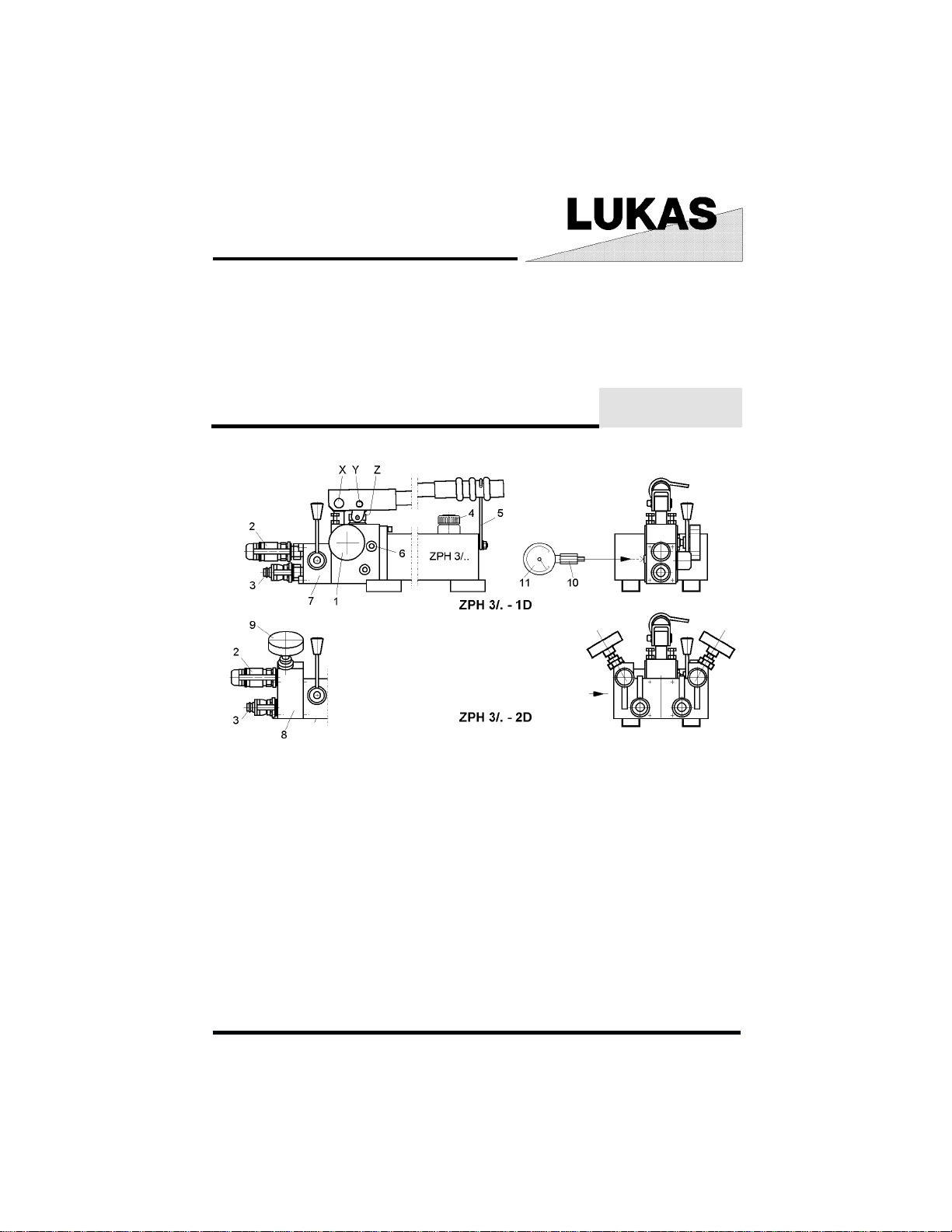
Hand pump ZPH 3 /. - .
1 drain valve Hand pump
2 Quick connect socket StMu-61O
3 Quick connect plug StNi-61
4 Venting- / filling cap
5 Clamp
6 Pressure limiting valve
7 4/2-way valve N4/2W
8 2D block
9 Control valve 2D block
possible accessories
10 pressure gauge connector MA2
11 Pressure gauge
84072/6680-85 GB
Issue 7.99
1

1 Basic operation and designated use of the machine
1.1 The machine has been built in accordance with state-of-the-art standards and the recognized
safety rules. Nevertheless, its use may constitute a risk to life and limb of the user or of third
parties, or cause damage to the machine and to other material property.
1.2 The machine must only be used in technically perfect condition in accordance with its
designated use and the instructions set out in the operation manual, and only by safety-conscious
persons who are fully aware of the risks involved in operating the machine. Any functional disorders,
especially those affecting the safety of the machine/plant, should therefore be rectified immediately!
1.3 The machine is exclusively designed for the use described in the operating manual. Using
the machine for purposes other than those mentioned in the manual, such as driving and controlling
other pneumatic systems, is considered contrary to its designated use. The manufacturer/supplier
cannot be held liable for any damage resulting from such use. The risk of such misuse lies
entirely with the user.
Operating the machine within the limits of its designated use also involves observing the instructions
set out in the operating manual and complying with the inspection and maintenance directives.
2 Organizational measures
2.1 The operating manual must always be at hand at the place of use of the machine!
2.2 In addition to the operating instructions, observe and instruct the user in all other generally
applicable legal and other mandatory regulations relevant to accident prevention and environmental protection.
This also applies for wearing protective clothing, helmet with visor or goggles and protective
gloves.
2.3 In order to avoid innjuries, the machine must only be operated by a specially trained operator
who has undergone a safety training.
2.4 Observe all safety instructions and warnings attached to the machine. Make sure that safety
instructions and warnings attached to the machine are always complete and perfectly legible.
2.5 Never make any modifications, additions or conversions which might affect safety without
the supplier's approval. This also applies to the installation and adjustment of safety devices and
valves.
2.6 Spare parts must comply with the technical requirements specified by the manufacturer.
Spare parts from original equipment manufacturers can be relied to do so. It is only allowed to use
original LUKAS spare parts of LUKAS system components.
2.7 Replace hydraulic hoses at the specified or adequate intervals, even if no defects are detected
which might affect safety. This must be done after 10 years, at the latest!
2.8 Adhere to prescribed intervals or those specified in the operating manual for routine checks
and inspections.
2.9 Make sure to dispose properly of packing material and dismounted parts!
3 General safety instructions
3.1 In the event of malfunctions, stop the machine immediately and lock it. Have any defects rectified
immediately.
2

3.2 Before starting up or setting the machine in motion and during operation of the machine make
sure that nobody is at risk.
3.3 Before transporting the machine always check that the accessories have been safely stowed
away.
3.4 Make sure that there is enough lighting during work.
3.5 Avoid any operation that might be a risk to machine stability.
3.6 Check the machine at least after every operation for obvious damage and defects. Report any
changes (incl. changes in the machine’s working behaviour) to the competent organization /person
immediately. If necessary, stop the machine immediately and lock it. All lines, hoses and screwed
connections have to be checked for leaks and obvious damage. Repair damage immediately.
Splashed oil may cause injury and fire.
3.7 All safety equipment has to be checked for completeness and flawless condition:
- instruction markings and warning signs (safety instructions)
- check safety cover (e.g. motor-safety covers, heat protection etc.) if they are available and if they
are in good condition.
3.8 Working under loads is not allowed if they are only lifted by hydraulic cylinders. If the work is
indispensable sufficient mechanical supports are needed additionally.
3.9 Do not stress hoses mechanically (pulling, buckling etc.).
4 Instructions for maintenance and service
4.1 For the execution of maintenance and service work, tools and workshop equipment adapted
to the task on hand are absolutely indispensable.
Work on the hydraulic system must be carried out only by personnel having special knowledge and
experience with hydraulic equipment.
4.2 Before putting into operation clean the machine, especially connections and threaded unions,
of any traces of oil, fuel or preservatives before carrying out maintenance/repair. Never use
aggressive detergents. Use lint-free cleaning rags and pay attention that the components are
meticulously clean during reassembling after repair.
4.3 During dismantling of machines it is necessary to collect the outrunning hydraulic liquids
completely, so that they cannot reach the ground. They have to be disposed properly according to
the instructions.
4.4 Always tighten any screwed and thread connections that have been loosened during
maintenance and repair. Observe the stipulated torques.
4.5 Work on the electrical system or equipment may only be carried out by a skilled electrician
himself or by specially instructed personnel under the control and supervision of such electrician
and in accordance with the applicable electrical engineering rules.
4.6 The electrical equipment of machines is to be inspected and checked at regular intervals.
Defects such as loose connections or scorched cables must be rectified immediately.
4.7 Aggressive material (acid, lye, solvent, vapour) can damage the machine. It is necessary to
clean the whole machine if it must be exceptionally operated under such conditions or gets into
touch with these materials. Additionally, the machine must be checked as described under 3.6.
3

5 Safety Instructions for Hydraulic hoses
All instructions as to safe use of hydraulic hoses can be found in the booklet HR 1495 35 219
deliverd with the hoses.
6 Intended use
The hand pump ZPH 3/... serves mainly for operation of LUKAS double-acting cylinders. Jt must
be used only in connection with components out of the LUKAS Rerailing System or the Hydraulik
Tools System 50 MPa, resp. 70 MPa.
An operation of cylinders other than LUKAS is possible, but it must be approved by LUKAS in
each individual case.
Warning
The system operating pressure must not exceed the pressure rating of the lowest rated component
in the system.
Warning
NEVER set the relief valve to a higher pressure than the maximum rated pressure of the pump.
Higher settings may result in equipment damage and/or personal injury.
7 Description
All ZPH/ series hand pumps have the two-stage design, i. e. they are working with two different
speeds:
a high speed in the low-pressure range (LP) for fast extension of a cylinder without load and a low
speed in the high-pressure range (HP) for controlled extension of a cylinder with a load resting on
it.
Switch-over from low to high pressure mode is done automatically by a factory-preset switch-over
valve (see also technical data).
8 Putting into Operation
8.1 Preparing the pump
The pump is to be connected to a hydraulic cylinder by means of suitable hydraulic hose pairs.
Permissible hose pairs (red/blue)
- 5m (ref. 84072/1764)
- 10m (ref. 84072/1765)
The hose pair (with quick couplers) is to be connected directly to the quick couplers on the pump
head: red hose to connection A, blue hose to connection B.
Before pumping: Open the oil filter cap (4) by approx. 1/2 rotation (turn left) and swing away the
clamp (5)
8.2 Connection of hose coupling to cylinder and hand pump
Before coupling, remove the dust protection covers and unlock the connect socket with adjusting
ring by turning it. Withdraw the sleeve and connect plug and socket while holding the sleeve in
this position. Release the sleeve and set the showglass to „red“ with the adjusting ring. Now the
parts are connected and locked. Decoupling is done in the reverse order.
4
8.3 Venting the cylinder
Connect the cylinder with the pump. Extend the piston by half its stroke and turn the cylinder so
that the piston is facing downwards. The highest point of the cylinder must be on a lower level
than the pump. Fully extend the piston and retract again so that eventual air bubbles can escape
into the oil container of the pump.
Remark:
The oil filler cap of the pump must be open during bleeding.
9 Operation of one double-acting cylinder
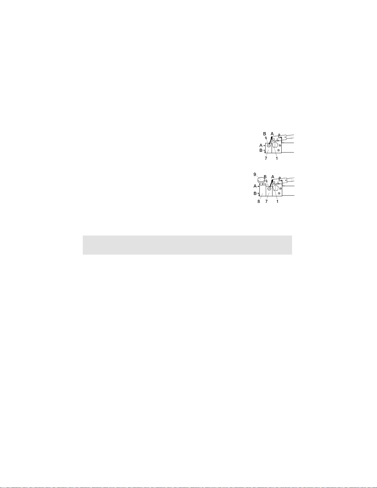
- fully close the hand wheel (1) by turning it clockwise
- switch the hand lever on the 4/2-way (7) valve to position A or B
(extension or retraction).
- activate the cylinder by operating the pump lever. Observe safety
remarks as per para 11.1 !
10 Operation of two double-acting cylinders
- fully close the hand wheel (1) of the hand pump and the
hand wheels (9) on the block 2D by turning it clockwise
- switch the hand lever on the 4/2-way (7) valve to position A or B
(extension or retraction).
- To effect extension resp. retraction of one or both cylinders switch
the hand lever on the 4/2-way (7) valve to position A or B . A synchronism
of both cylinders can be achieved by different opening / closing of the hand wheels.
Observe safety remarks as per para 11.1 !
for Pos. 9 and 10:
The 4/2-way valve (N4/2W) itself does not have such a function.
Load can be sustained when the hand wheel (1) is fully closed. The lever of the N4/2W valve must
thereby stay in position „extending“.
11 Lifting a load
11.1 Safety remarks as to safe use of the hand pump
Caution!
NEVER add extensions to pump handle. Extensions cause unstable pump operation.
Warning!
In certain situations the pump handle can "kick back". Always keep your body to the side of the
pump, away from the line of force of the handle.
Note
To reduce handle effort at high pressure, take short strokes. Maximum leverage is obtained in the
last 5 degrees of stroke.
11.2 Observe „Safety measures prior to and during lifting“ as per separate operating
manual of your LUKAS cylinder.
12 Lowering a load (pressure release)
12.1 Open the oil filling cap (4) on the reservoir a few turns
12.1.1To retract the piston of the cylinder, open the drain valve of the pump carefully (..1D resp.
on the block ..2D) (rotation to the left). Closing the drain valve (rotation to the right) will interrupt the
drain process. By means of fine adjustment of the drain valve, an extremely precise retraction of
the piston of the cylinder is facilitated.
5

12.2 Special function „quick stop“
If you open the drain valve rapidly (rotation to the left), an existent quickstop only for 50 MPa
cylinders StMu61-M (silver) is activated, i.e. a non-return valve, incorporated in the quick-connect
coupling, will prevent the oil from flowing back. While the hose is at zero pressure, the cylinder
remains under pressure. Pump and cylinder can now be separated and the pump can be used
elsewhere.
The "quickstop" also serves as a safety valve if for some reason the hose is damaged. The
quickstop will in this case prevent the load from falling.
In order to release the quickstop, the pressure in the cylinder must be increased with a few pump
slaps. This will re-open the non-return valve in the quick-connect plug StNi 6. The draining can
now be continued.
12.3 Uncoupling pump and cylinder
Before uncoupling the pump from the cylinder, make sure (by opening the drain valve) that there
is no pressure and that the piston is completely retracted.
Remount the protection caps after uncoupling in order to avoid pollution of the coupling parts.
Close the oil reservoir filler cap, so that no oil is spilled during transport.
12.4 Adjustment of the maximum pressure (50 MPa)
or if necessary of a lower pressure
Check adjusted pressure with closed drain valve.
Adjust pressure limiting valve (item 6, see cover page) as follows:
- Unscrew the screw plug 6.1 (SW5), with the hexagonal socket-head wrench
(SW4) adjust the nut 6.2 to the intended pressure.
Note:
Rotation to the right = pressure increase; Rotation to the left = pressure relief.
The pressure can be seen on the connected pressure gauge.
Caution: Observe para 6 of this operating manual!
13 Servicing and Maintenance
Oil should be changed once a year. In case of frequent use or operation in particularly dusty
environment, oil should be changed every six months.
13.1 Adding Oil to the Pump
Warning: Always add oil with cylinders fully retracted (extended if pull cylinders) or the system will
contain more oil than the reservoir can hold.
- Remove vent/fill cap from reservoir.
- Fill reservoir only to level mark shown on pump.
- Remove air from system if necessary. See 8.3. Recheck oil level after removing air.
- Return vent/fill cap to proper position.
- Make sure no dirt gets into the oil reservoir or into the pump, as this will cause malfunction.
- To extend pump life and improve performance, lubricate the beam pin X, cross pin Y and
piston head Z regulary, using roller bearing grease (see cover page).
6

14 Trouble shooting
Problem Possible Cause Solution
Cylinder does not
advance,
advances slowy,
or advances in
spurts.
Cylinder
advances, but
does not hold
pressure
Cylinder does not
retract, retracts
part way, or
retracts more
slowly than
normal
If the defects cannot be repaired, contact an authorised LUKAS dealer or the LUKAS service
department. The address:
LUKAS Hydraulik GmbH, Weinstraße 39, 91058 Erlangen, P.O.B. 2560, 91013 Erlangen,
Germany, service phone 09131/698 348; fax 09131/698 353
Oil level in pump reservoir is low. Add oil according to the Maintenance instructions on 12.1
Drain valve open Drain valve closed
Loose hydraulic coupler Check that all couplers are fully tightened
Load is too heavy Do not attempt to lift more than rated tonnage
Air trapped in system Remove air according to the instructions on page 8.3
Cylinder plunger binding
Leaking connection Check that all connections are tight and leak free
Leaking seals
Internal leakage in pump
Drain valve closed Open drain valve
Pump reservoir is over-filled
Loose hydraulic coupler Check that all couplers are fully tightened
Air trapped in system Remove air according to the instructions 8.3
Hose I.D. too narrow Use larger diameter hydraulic hose
Cylinder retraction spring broken
or other cylinder damage
Check for damage to cylinder; have cylinder by a
authorised dealer or LUKAS themselves
Locate leak(s) and have equipment serviced by
authorised dealer or LUKAS themselves
Have pump serviced by a authorised dealer or LUKAS
themselves
Drain oil level to full mark. See 12.1 instructions for
adding oil
Have cylinder serviced by a authorised dealer or LUKAS
themselves
15 T echnical dat a
epyTD1-8/3HPZD1-4/3HPZ
.onredrO0866/270480466/27048
)*aPM(erusserpgnikroW05
)l(yticapaclioelbasU/yticapacliO8/5,014/52,5
)³mc(PH/PLyreviledliOekortsnotsiprep2,4/8,01
)*aPM(revo-hctiwscitamotuA81
)mm(hxwxlsnoisnemiD281x032x519281x031x519
)gk(liohtiwthgieW2,8151
* 10bar = 1 MPa
7

epyTD2-8/3HPZD2-4/3HPZ
.onredrO5866/270488466/27048
)*aPM(erusserpgnikroW05
)l(yticapaclioelbasU/yticapacliO8/5,014/52,5
)³mc(PH/PLyreviledliOekortsnotsiprep2,4/8,01
)*aPM(revo-hctiwscitamotuA81
)mm(hxwxlsnoisnemiD281x062x049
)gk(liohtiwthgieW8,026,71
* 10bar = 1 MPa
15.1 Oil recommendations
For LUKAS hydraulic devices, use mineral oil in accordance with DIN 51 524 and others
Range of oil temperature Viscosity rating Remarks
A - 24... + 30°C HL 5
B - 18... + 50°C HLP 10
C - 8... + 75°C HLP 22
D + 5... + 80°C HLP 32
E - 8... + 70°C HF - E15 biodegradable
Recommended viscosity range: 10 ... 200 mm²/s, delivered with HLP 10 to DIN 51 524
LUKAS Hydraulik GmbH
A Unit of IDEX Corporation
Weinstraße 39, 91058 Erlangen • Germany
Postfach 2560, 91013 Erlangen • Germany
Telefon +49 (0)9131/698-0 • Telefax +49 (0)9131/698-394
84072_6680_e.P65
© Copyright 1999 LUKAS Hydraulik GmbH
8
 Loading...