

84128/1875-85 GB
Issue 06.2008
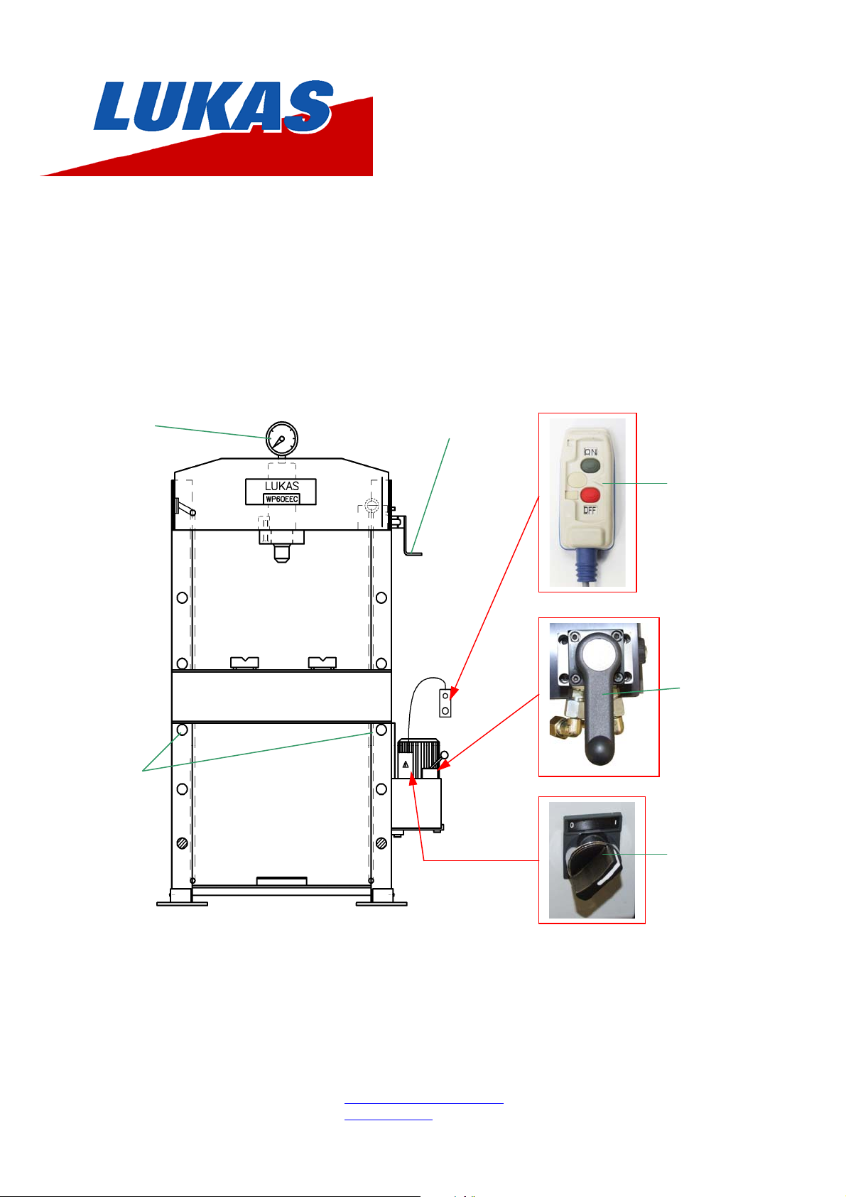
COLUMN PRESS 60 ton
WITH ELECTRIC PUMP
“WP60EEC”
Pressure
gauge
Crank
Remote
control
Distributor
valves
Axle pins
ON/OFF
Switch
LUKAS
A Unit of IDEX corporation
Weinstraße 39, D-91058 Erlangen
Postfach 2560, D-91013 Erlangen
Telefon: +49 (0)9131 / 698 - 0
Telefax: +49 (0)9131 / 698 - 394
E-mail: lukas.info@idexcorp.com
Internet: www.lukas.de
Hydraulik GmbH
Instruction Manual
Column Press with Electric Pump “WP60EEC”
INDEX
1. BEFORE USING THE EQUIPMENT ................................ 2
2. TECHNICAL FEATURES ................................................. 2-3
3. ESSENTIAL SAFETY REQUIREMENTS ......................... 3-4
4. TRANSPORT AND INSTALLATION ................................ 4
5. START UP ........................................................................ 5
6. MAINTENANCE, PROBLEMS AND SOLUTION ............. 6
7. WARRANTY ..................................................................... 6
8. CE - DECLARATION OF CONFORMITY......................... 7
Before unpacking the equipment check for:
1- Oil leaks, signs of corrosion.
2- Damage to the hydraulic cylinder or hydraulic line.
3- Damages in the frame and the accessories.
4- Damages or lack of screws and connections.
5- Damaged or incorrectly assembled accessories.
If you observe any fault or damage in the equipment, avoid its use and store it in a safety place until be repaired by an authorized service dealer.
Never use hydraulic equipment that is damaged or suspected to be in poor condition.
The operators have to familiarize themselves with the equipment before using the machine. Read and observe exactly the instructions and the
recommendations included in packaging. Any inadequate use of the equipment not observed in the present manual or the omission of this one, ma y
cause serious personal and material damages, which LUKAS will not be responsible in any case.
Do not loose the instruction manual.
Do not work with the equipment near open flame, explosives, heat sources or any other source that may produce fire or cause damages to the
equipment. The equipment must not be exposed to temperatures higher than 60ºC when in use or when stored.
When you have located a good place for the press, assure that it is in solid and flat ground. The entire base of the press must be supported. If there is
any doubt about the stability, it is recommended distributing the weight (weight of press, accessories and max. additional weight of the components
which should be pressed) over a larger area, e. g. by placing sufficient large and stable steel-plates under the base of the press.
Store the press with the piston fully retracted. In order to have the press correctly storage, we recommended protecting the cylinder with a plastic film or
locating the press in a clean place, so neither the press nor their components could be damaged
If purchasing a cylinder or pump for use in the press, which is not an original spare part, ensure that you are using the proper combination of pump,
cylinder and press frame before assembling the unit. I n this case , we re commend y ou to ask for profe ssion al advice from LU KAS direct.
1. BEFORE USING THE EQUIPMENT
.2. TECHNICAL FEATURES
HYDRAULIC CYLINDER
60 t
70 MPa
180 mm
86.59 cm²
1558.6 cm³
5.7 mm/s
1 mm/s
POWER PACK:
• Max. pushing capacity (t)
• Max. operating pressure (MPa)
• Hydraulic stroke (mm)
• Effective area (cm²)
• Oil capacity (cm³)
• Extension speed, without load (mm/s)
• Extension speed at maximum pressure
• Tank capacity (l)
• Low pressure oil flow. Rapid advance
• High pressure oil flow. Working
• Maximum operating pressure (MPa)
• Maximum pressure in retraction (MPa)
• Distribution valve
• Motor
6 l
3 l/min.
0.56 l/min
70 MPa
10 MPa
4 ways / 3 positions hand valve
0.75 kW; 380/220 V; 50 Hz.; 3-phase current
2
Instruction Manual
FRAME: mechanized-welded frame with mobile table and anchor bolt system
Column Press with Electric Pump “WP60EEC”
• Max. working height (mm)
• Min. working height (mm)
• Sequence of table positioning
(mm)
• Working width (mm)
• Total weight (kg)
935 mm
110 mm
165 mm
860 mm
470 Kg
3. ESSENTIAL SAFETY REQUIREMENTS
Due to the functional reasons, "dangerous area" is considered to be the space between the columns, the table and the hydraulic cylinder piston.
Due to the material pressed, "dangerous area" is supposed to be the surrounding area to the machine in case of metal parts being ejected
The speed of the hydraulic cylinder during its extension is less than 30 mm/second. Therefore then machine should be considered by the application of
ANNEX V of the Declaration of CE Conformity.
Operators standing in the da nger ou s area around the ma chin e shou ld pro tec t the ir fe et, f ace s and ha nds f rom me ta l pie ces be ing ejected during pressing.
There are not risks for the health and safety of the operators by the used materials and components, if they are used corr ect ly. The motor pum p contain s LUKAS
hydraulic oil (type ISO: HV46).
during pressing.
Feet protection Face protection Hands protection
IN ANY CASE, HYDRAULIC OIL IS TOXIC IF IT TAKES CONTACT THE HUMAN BLOOD STREAM, SO NEVER PLACE THE FINGERS
OVER ANY HOLE THAT MAY CAUSE AN INJECTION INTO THE HUMAN BLOOD STREAM WHEN THE PRESS-SYSTEM IS
PRESSURIZED.
The start and stop operations of the moto r are made with the com mands of IP55 el ectric remote control bo x. The co mmands are supplied with a
24 V. tension.
The advance and return movements of the cylinders are made by the hand lever located in the pump. This lever actuates over a directional
valve.
The operator can always interrupt the movement of the cylinder independent of the kind of operation that the equipment makes, because the
operator sometimes must place its hands over the material to be treated. This forces the operator, to know the inherent risks and the operating
of the equipment.
The starting up of the motor is carried out by the ON/OFF switch located on the electric box of the pump. (ON = 1 / OFF = 0)
The rest of operating devices are activated manually from the directional valve on the cover of the pump.
To get cylinder movements, it is necessary to push the green button on the electric remote control box.
If you stop pressing the green push button, the motor stops and with it the cylinder movements. (The red push button has no function!)
The machine is equipped with the fuse and a thermo-magnetic switch for its protection.
The machine is equipped with supporting plates on the columns for a perfect stability. The machine gets operated without fixing onto the floor,
but it is strongly recommended to do it by drilling the plates in the place of your choice.
The construction of machine has been calculated to bear without any breaking under conditions of foreseen utilization and for the whole life of
the machine.
The hydraulic components have been designed and calculated in compliance with the ANSI B30.1
It is operator's responsibility to wear special protective clothes and attachments in both feet and face to prevent an y damage as a result of
accidental fallings and breakings of metal pieces under operation or machine components in touch with.
Risks due to surfaces, bends and angles:
o Risk due to mobile components in setup stage: The table can be positioned in several fixing points (weight of the table 21,5 Kg).
The EE06018 model is provided with a winch for the displacement of the table. It is operator's responsibility to wear safety shoes in
any case. There are 2 axle pins in equivalent holes of the lowest position to prevent operator's feet from being caught by the table.
o Risk due to mobile components during service: The operator must either move the directional valve lever to "C" position or
stop pressing the green button to fully stop the movement of the piston.
The frame of the machine does not cause to be dangerous in that sense.
3

Instruction Manual
SAFETY PREVENTIVE ACTIONS AGAINST OTHER RISKS
Risk due to power supply:
Risk due to hydraulic power:
MPa , as well as with a pressure relief valve on the tank cover adjustable by the operator from 0 to 70 MPa.
furnisher with a pressure relief valve, rated at 70 MPa, which prevents the retraction chamber of the cylinder from overpressures in case of
obstruction of the return way.
All the maintenance operations must be performed while the machine is stopped, thus avoiding this way any potentially dangerous situation.
A poor maintenance program of the press does not increase the risk, but obviously will revert in a lower performance.
The hydraulic pump is mounted in the frame and access is very easy. To disassemble the pump, unscrew the bolts in the tap cover. In order to
disassemble the cylinder it is required to first disassemble the piping.
Isolation of the power supply:
Handling by the operator: The machine is designed to assure that all maintenance tasks are performed by the operator in an easy and safe wa y.
All the components that would require any maintenance operation are easy accessible.
In the valve, you can find several marks depending on the position of the lever:
• "A" for extension of the cylinder piston.
• "B" for holding the pressure without piston movement.
• "C" fir retraction of the cylinder piston.
The press, the cylinder and the electric pump have their corresponding serial numbers marked on them. In addition to it, you can find a sticker label
showing the commercial reference, capacity, working pressure, name and address of the manufacturer.
The machine is equipped with the fuse and a thermo-magnetic switch for its protection.
The hydraulic pump is equipped with an internal security valve in the tank, out of operator's control and rated at 70
Release the terminal wiring to disconnect the power supply. Previously you should unplug the pin.
Column Press with Electric Pump “WP60EEC”
The hydraulic cylinder is also
4. TRANSPORT AND INSTALLATION
The machine is delivered properly packed in a wooden ballet. For it’s handling, it is recommended to use a forklift truck or a crane. In the last case, it is
necessary to make the slings trespass the arc of the frame. When doing this operation, you should be cautious a nd prevent the flexible hoses and
couplings from any damage.
Bear in mind the voltage indicated in the terminal box of the motor. Assure that the directional distributor valve’s command is in position “C”.
Check that the motor rotates in the sense of the arrow labelled in the electrical motor. In opposite case, change the position of two cables between
themselves in the terminal and try again. This operation will be made with the equipment depressurized.
SUBSTITUTION OF THE TRANSPORT PLUG
Replace the plug of transport located in the cover of the tank, by the pressurized plug given with the press. (Plastic bag on the lever of the valve).
INSTALLING THE GAUGE
1-Replace the threaded tap at the top of the cylinder by the gauge. (Supplied separately).
2-Tighten the gauge cone to the gauge adaptor seat by using a flan wrench size 22.
3-Hold the gauge screen by hand during threading process and after reaching a comfortable reading position set the gauge screen free so that it turns
the last quarter solidary with the thread.
4- The hydraulic system also includes a gauge adaptor with 3/8 “BSP thread.
CHECKING THE RIGHT OPERATION OF ALL DEVICES AND MECHANISM
The machine is stable enough to operate without fixing, but if is placed in an area commonly operated by mobile machinery (cranes, lifting
equipment…) it is strongly recommended to fix it to the desired place by drilling the supporting plates.
1. Switch the black ON/OFF Switch on the electric box to position “1”.
2. Switch the distributor valve’s command to position “C”, push the green push button of the remote control and do not stop pushing it.
3. Check the rotate of the motor.
4. If the rotate sense is the opposite of the labelled arrow in the motor, change the phases of the electrical connection. Disconnect the
equipment for this operation.
5. Switch the distributor valves command to “A” position. The cylinder’s piston advances, familiarize with the speed.
6. Guide the piston to the end of the stroke and submit to pressure, check the reading of the gauge and that there is not oil leaks.
7. Switch the distributor valves command to “C” position to assure that the cylinder maintains the pressure.
8. Switch the distributor valves command to “B” position to return the piston, familiarize with the speed.
9. Stop pushing the green button on the remote control, to stop the motor. Move the command from “A” position to “B” position to depressurize
the cylinder and finally let the distributor valve’s command in “C” position.
10. Switch the black ON/OFF Switch on the electric box to position “0”.
4

Instruction Manual
Column Press with Electric Pump “WP60EEC”
5. START UP
Connect the machine as explained in the previous point.
Displacement of the table’s height:
MODELS WP60EEC
Choose the wished height.
Elevate the table rotating the crank of the winch on the right, until the axle pins could be extracted.
Put the table in the wished height, take care, that the holes of the columns directly below the table are free in order to slide the
axle pins into the holes.
Descend the table by means of the winch, until the table is perfectly supported by the axle pins so that the steel cables of the
winch are without tension.
VERY IMPORTANT! THE POSITIONING SYSTEM OF THE TABLE IS NOT DESIGNED TO RESIST THE FORCE THAT THE CYLINDER IS
ABLE TO DO. Its USE IS ONLY IN ORDER TO POSITIONING THE TABLE.
Regulation of the maximum working pressure:
The maximum pressure developed by the hydraulic system is 70 MPa. An internal limiter valve races in the moment that the installation reaches t he
pressure.
If the working pressure wished is inferior, act in the following sense:
1. In the cover of the power pack is located the pressure regulation screw.
2. Release the lock nut and go releasing the regulation screw. Go checking with the ga uge and once th e pressure wished is reached, tighten the
lock nut to avoid that the vibrations deregulate the system.
5

Instruction Manual
Column Press with Electric Pump “WP60EEC”
6. MAINTENANCE, PROBLEMS AND SOLUTION
The hydraulic circuit of the press is closed, so in normal conditions no oil leakage should be coming up.
In case of oil leakage, after the proper repairing work, you should fill up the tank with LUKAS hydraulic; the pump is equipped with an oil level indicator
to control the need quantity of oil.
As far as a non-continuous use of the press is concerned (1 hour per day), oil replacement should be done once a year.
USE ONLY LUKAS HYDRAULIC OIL
Other grades of oils or types of hydraulic fluid (such as brake fluid) may affect the performance of the equipment or cause the deterioration of the seals.
Always use the original LUKAS parts to prolong the service life of your hydraulic equipment. LUKAS or your authorized dealer can supply you with
original parts for simple maintenance work
The solutions marked in black must be carried out by specialized personnel. We remark to contact your authorized distributor that sold you the
equipment or to LUKAS directly.
Always use original LUKAS spare parts, you will extend the life utility of the equipment, in opposite case the company will not become person in charge
of the possible failures, damages or losses that take place.
To empty the tank, you should remove the cover and take the oil out to another co ntainer. Please, bear in mind the existing rules for waste
processing when handling the used oil.
Keep greasy and lubricated the pin bearings, the piston and in general all the parts that might be in friction.
DO NO ATTEMPT TO FILL THE PUMP WITH OIL WHILE IT IS CONNECTED TO A CYLINDER WHICH IS SUSTAINING A LOAD
BECAUSE IT MAY OVERPRESSURIZE THE RESERVOIR WHEN THE PISTON RETRACS AND CAUSE DAMAGE OR INJURY
PROBLEMS POSSIBLE FAILLURES SOLUTION
1. The piston does not advance. - Prime fewer pumps. 1. Feed the pump keeping it started some minutes.
- Dirty accumulated in the filter. 2. Extract and clean it.
- No or not enough oil in the
reservoir.
- Cylinder pressure retainer
damaged.
- Directional valve damaged. 5. Replace the valve.
- Cylinders body damaged. 6. Repair the body of the cylinder.
- Hydraulic problem. 7. Check the installation.
2. The cylinder does not reach pressures. - Pressure relief valve unrated. 8. Rate the valve.
- Cylinder pressure retainer
damaged.
- Cylinders body damaged. See Solution. 6.
3. The cylinder does not maintain pressure. - Cylinder pressure retainer
damaged.
- Directional valve damaged. See Solution. 5.
4. The cylinder does not retract. - Directional valve damaged. See Solution. 5.
3. Check the level.
4. Replace the retainer.
See Solution. 4.
See Solution. 4.
7. WARRANTY
The two year LUKAS warranty starts from the date of purchase. This guarantee does not include:
- both metal and non-metal parts for
- using the equipment beyond its rated capacity
- any wear or damage incurred as a result of using a hydraulic fluid which is not recommended by LUKAS.
Please note that if the equipment is disassembled or serviced by anyone other than an authorized service dealer or by LUKAS., this guarantee is
rendered null and void.
In the event of a warranty claim, return the equipment, to LUKAS or your authorized dealer which sold you the hydraulic equipment.
LUKAS will repair or replace the faulty equipment, whichever is deemed most appropriate.
LUKAS shall not be held liable for any consequential damages or losses, which may occur as a result of faulty equipment.
routine maintenance and expendables,
6

Instruction Manual
Column Press with Electric Pump “WP60EEC”
8. CE - DECLARATION OF CONFORMITY
7
 Loading...