

Page 1
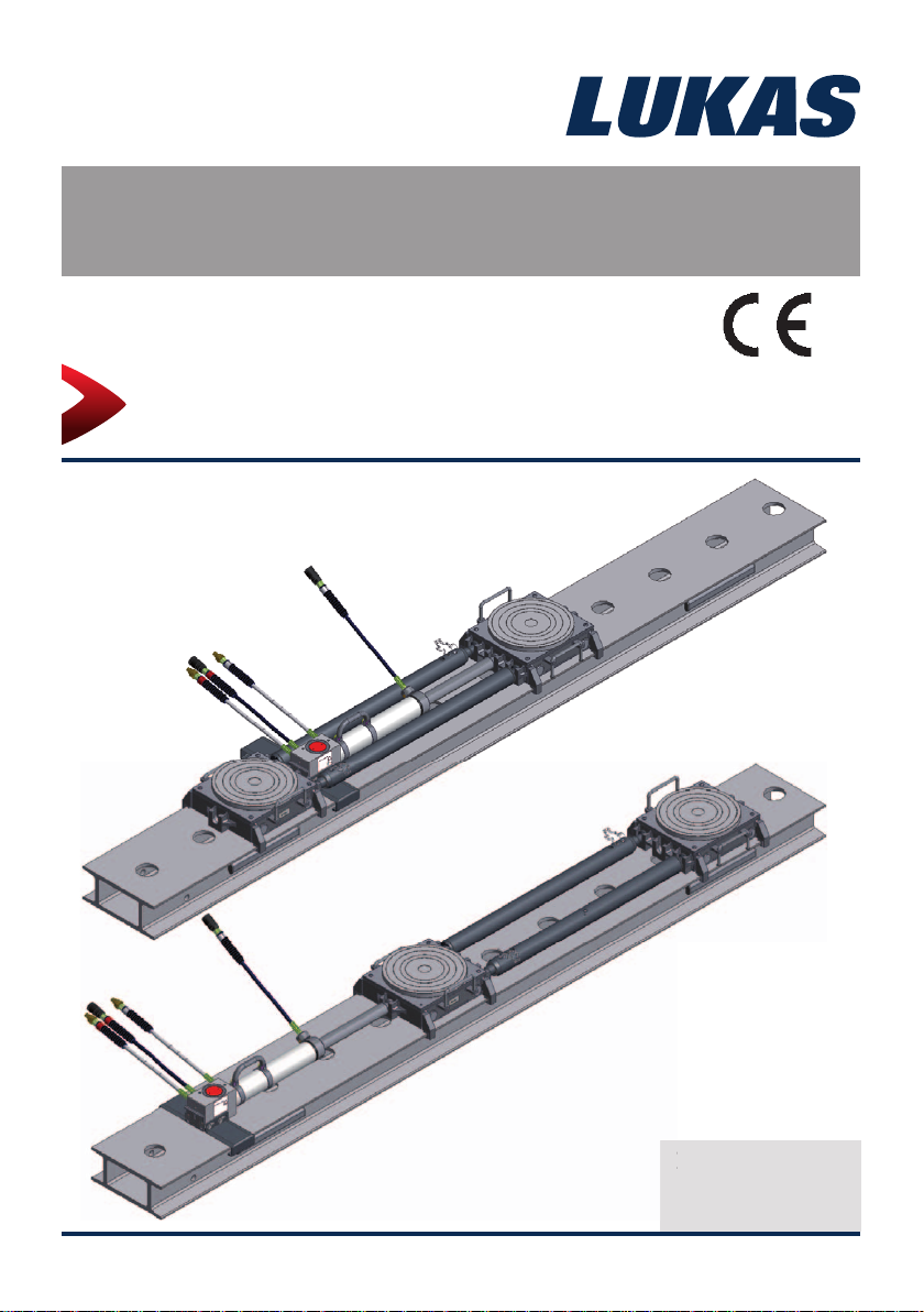
Instruction Manual
30000085 E
01
Rerailing Equipment
LUKAS traversing system
(Translation of the original instruction manual)
1430000085 EN
14
Edition 09.2014
Edition 09.2
Page 2

2
Page 3

Content Page
1. Danger classifi cations 4
2. Product safety 5
3. Proper use 8
4. Components and functions 9
4.1 Description 9
4.2 Hydraulic supply to the cylinders 10
5. Connecting the hydraulic equipment 10
5.1 Basic aspects 10
5.2 Coupling the quick-disconnect couplings 11
6. Operation 12
6.1 Setting up the LUKAS traversing system 12
6.2 Start-up 25
6.3 Controlling the LUKAS traversing system with anchor pin 26
6.4 Controlling the DUO traversing cylinder with anchor cylinder 28
7. Dismantling the equipment / deactivation following operation 30
7.1 Hydraulic cylinder 30
7.2 Hoses 30
7.3 Additional components of the traversing system 30
7.4 Hydraulic supply, control and separate load lifting systems 30
8. Maintenance and service 31
9. Repairs 31
9.1 General information 31
9.2 Preventative service 32
9.3 Repairs 33
10. Troubleshooting 36
11. Technical data 38
11.1 Traversing cylinder 38
11.2 Rolling carriage 41
11.3 Rerailing bridges 41
11.4 Connecting rods 42
11.5 Recommended hydraulic fl uids 43
11.6 Operating and storage temperature ranges 43
12. Declaration of conformity 44
13. Notes 45
3
Page 4
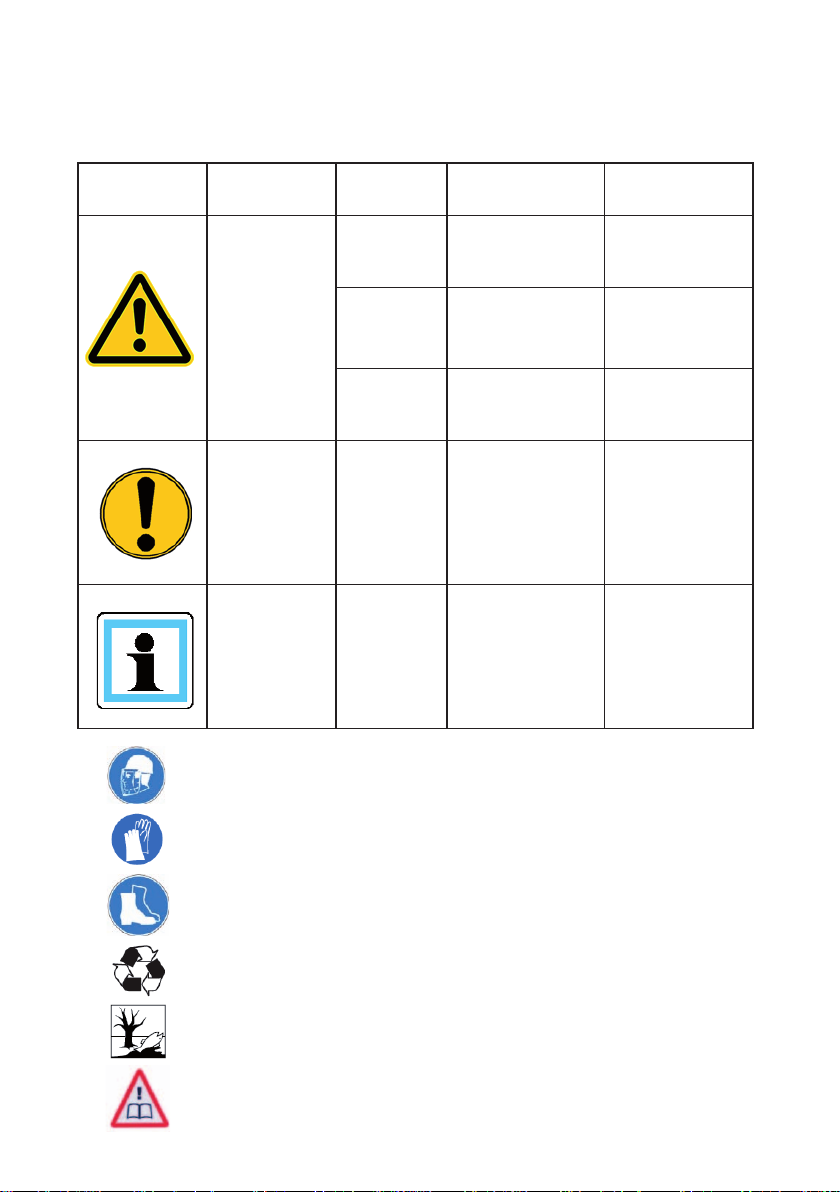
1. Danger classifi cations
We differentiate between various different categories of safety instructions. The table shown
below provides an overview of the assignment of symbols (pictograms) and signal words to
the specifi c danger and the possible consequences.
Pictogram
Damage /
injury to
Persons
Property
- NOTE
Key word Defi nition Consequences
DANGER! Immediate danger
WARNING!
CAUTION!
ATTENTION!
Potentially
dangerous
situation
Less dangerous
situation
Danger of damage
to property/
environment
Handling tips and
other important/
useful information
and advice
Death or severe
injury
Potential death or
serious injury
Minor or slight
injury
Damage to the
equipment,
damage to the
environment,
damage to
surroundings
No injury/damage
to persons/
environment/
device
Wear a helmet with a face guard
Wear protective gloves
Wear safety shoes
Proper recycling
Protect the environment
Read and follow the operating instructions
4
Page 5
2. Product safety
LUKAS products are developed and manufactured to ensure the best performance and
quality when used as intended.
The safety of the operator is the most important consideration in product design. Furthermore,
the operating instructions are intended to help in using LUKAS products safely.
The generally applicable legal and other binding regulations pertaining to the prevention of
accidents and protection of the environment apply and are to be complied with in addition to
the operating instructions.
The equipment must only be operated by persons with appropriate training in the safety
aspects of such equipment – otherwise, there is a danger of injury.
We would like to point out to all users that they should read carefully the operating instructions
and the instructions contained therein before they use the equipment, and that they should
carefully follow such.
We further recommend you have a qualifi ed trainer show you how to use the product.
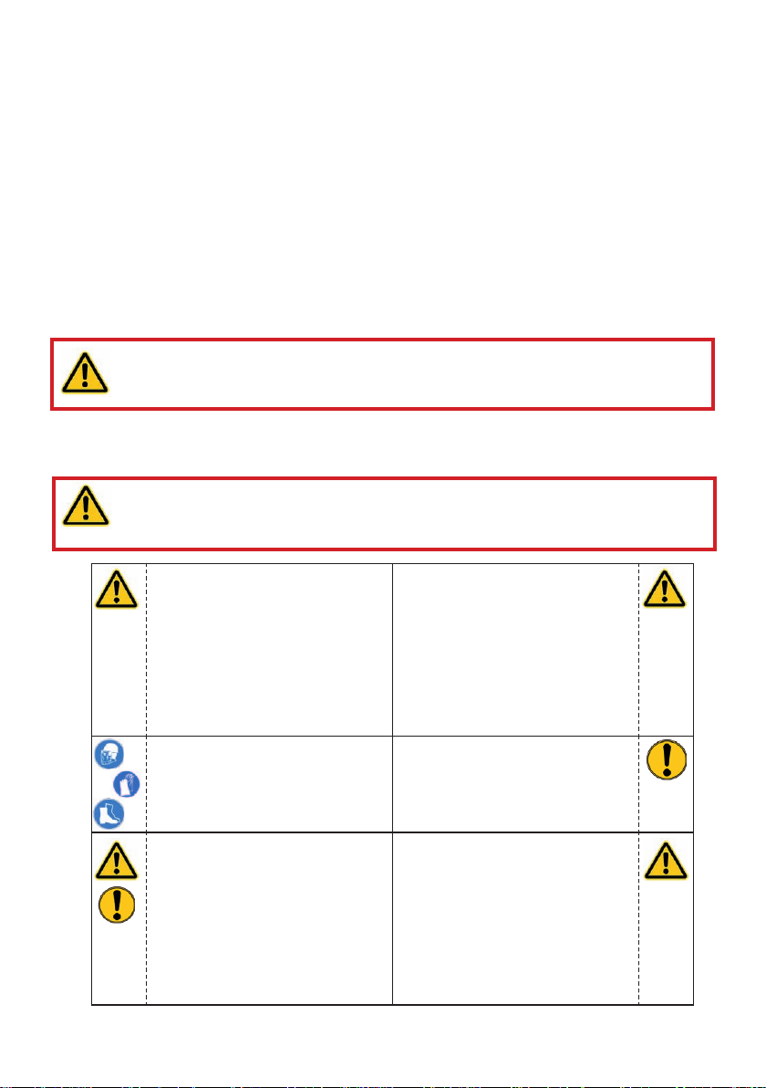
CAUTION!
The operating instructions for the hoses, the accessories and the connected
devices must also be heeded!
Even if you have already received instruction on how to use the equipment, you should still
read through the following safety instructions again.
WARNING / CAUTION!
Ensure that the accessories and connected equipment are suitable for the
maximum operating pressure!
Please ensure that no body
parts or clothing are caught
between the visibly moving
parts (e.g. piston guard plate
and cylinder).
Wear protective clothing,
a safety helmet with visor,
protective footwear and gloves
Immediately report any
changes that occur (including
changes in operating
behaviour) to the appropriate
persons/departments! If
necessary, the equipment is to
be shut down immediately and
secured!
Working under suspended
loads is not permitted where
such loads are being lifted
only using hydraulic devices.
If working under suspended
loads is unavoidable, suitable
mechanical props are also
required.
Inspect the device before and
after use for visible defects or
damage.
Check all lines, hoses and
screwed connections for leaks
and externally visible damage,
and repair immediately!
Escaping hydraulic fl uid can
cause injuries and fi res.
5
Page 6
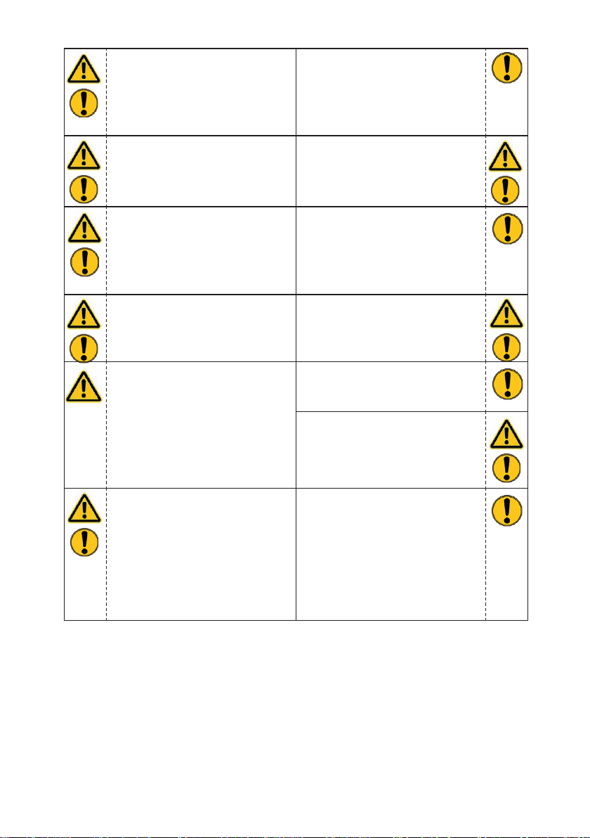
In the event of malfunctions,
immediately deactivate the
equipment and secure it.
Repair the fault immediately.
Do not carry out any changes
(additions or conversions)
to the equipment without
obtaining the approval of
LUKAS beforehand.
Observe all safety and danger
information on the device and
in the operating instructions.
Any mode of operation which
compromises the safety and/
or stability of the device is
forbidden!
Safety devices must never be
disabled!
Make sure before switching
on/starting up the device and
during its operation, that this
will put no one in danger.
When working close to live
components and cables,
suitable measures must be
taken to avoid current transfers
or high-voltage transfers to the
equipment.
All safety and danger
information on the device must
always be complete and in a
legible condition.
Observe all intervals for
recurring tests and/or
inspections that are prescribed
or stated in the operating
instructions.
The maximum permitted
operating pressure noted on
the equipment must not be
exceeded.
Only genuine LUKAS
accessories and spare parts
are to be used for repairs.
Please ensure that, when
working with this equipment or
during transportation of such,
you don’t get caught up in the
looped hoses and trip.
The build-up of static charge
and therefore possible
sparking must be avoided
when handling the device.
6
Page 7
The equipment is fi lled with
hydraulic fl uid. This hydraulic
fl uid can be detrimental to
health if it is swallowed or
its vapour is inhaled. Direct
contact with the skin must be
avoided for the same reason.
Also, when handling hydraulic
fl uid, note that it can negatively
affect biological systems.
When working with or storing
the equipment, ensure that the
function and the safety of the
equipment are not impaired
by the effects of severe
external temperatures or that
the equipment is damaged in
any way. Please note that the
equipment can also heat up
over a long period of use.
Make sure there is adequate
lighting while working.
Always keep these operating
instructions easily accessible
at the place of operation.
In addition to the safety instructions in this operating manual, all generally applicable,
statutory and otherwise binding national and international regulations for accident prevention
must be heeded and disseminated!
Before transporting the
equipment, always ensure that
the accessories are positioned
in such a way that they cannot
cause an accident.
Dispose properly of all
disassembled parts, oil and
left-over fl uid, as well as
packaging materials.
WARNING / CAUTION / ATTENTION!
The device is intended exclusively for the purpose stated in the operating instructions
(see chapter "Proper Use"). Any other use is not considered to be as intended. The
manufacturer/supplier is not liable for any damage resulting from use not as intended. The
user bears sole responsibility for such use.
Proper use includes observance of the operating instructions and compliance with the
inspection and maintenance conditions.
Never work in a fatigued or intoxicated state!
7
Page 8
3. Proper use
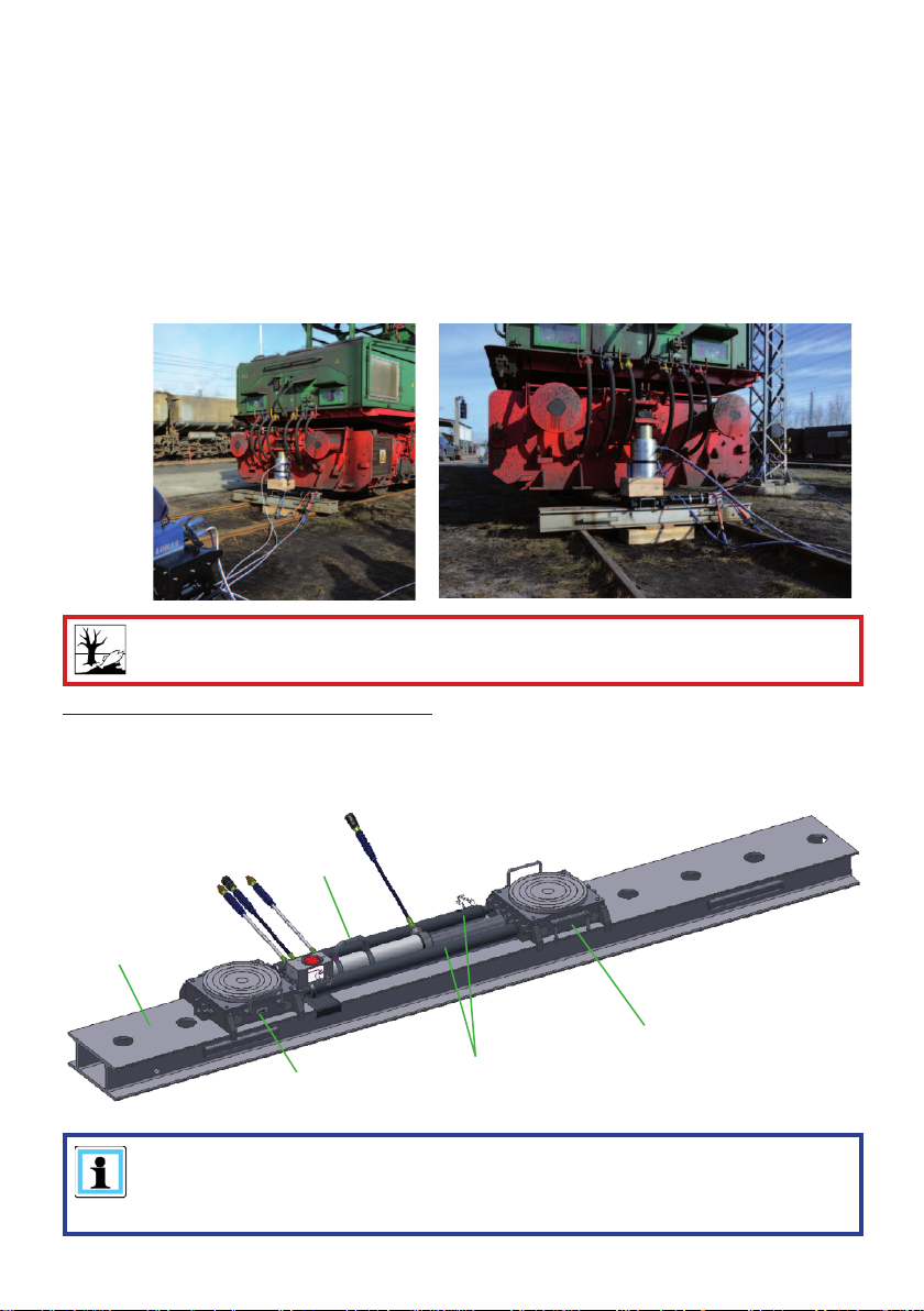
The components of the LUKAS traversing system are especially designed for re-railing
technology . They are used for rerailing of rail-bound vehicles. Derailed vehicles can be lifted
up and moved at right angles to the track.
The accessories necessary for the particular application, such as base plate, multistage sets
etc., must be used during each deployment.
When carrying out any work, use the traversing system described here and the connected
hoses and equipment to ensure that you yourself, the involved and uninvolved persons in the
proximity of the work and objects in closer proximity during the lifting and traversing process
are not endangered.
ATTENTION!
Watch out vigilantly for any leaks in order to avoid threats to the environment.
The LUKAS traversing system consists of:
- Item 1 Rerailing bridge
- Item 2 DUO traversing unit
- Item 3 Rolling carriage
- Item 4 Adjustable connecting rods
2
1
3
3
NOTE:
In order to be able to lift vehicles and move them, either lifted up or placed on
the traversing system, you need to use suitable lifting equipment (e.g. LUKAS
HP cylinders) and their accessories.
4
8
Page 9

4. Components and functions
4.1 Description
4.1.1 Rerailing bridge
The rerailing bridge is placed at right angles over the tracks and provides the support and
moving surface for the LUKAS rolling carriages and the DUO traversing unit.
If one bridge is not long enough, a second bridge can be screwed on by means of joining
elements.
The integrated anchor cylinder locates as a locking pin in the arresting openings in the top of
the rerailing bridge. The rerailing bridges are transported using the pull-out handles mounted
at the sides.
4.1.2 Rolling carriages
The LUKAS rolling carriages are designed to carry heavy loads. The special rollers on the
bottom of the rolling carriage mean that it can be moved in the rolling direction by hand or
using traversing cylinders. The rolling carriages are specially adapted to LUKAS rerailing
bridges and provide optimum movement for the load.
The top slide plate on the rolling carriage is placed on the carriage and can be rotated
and moved at right angles to the rolling direction. The movements arising during lifting and
traversing are thus given more room. Tipping of the rolling carriage or a cylinder mounted on
it is prevented if positioned correctly.
4.1.3 DUO traversing unit
The DUO traversing unit is designed to move the LUKAS rolling carriages on the rerailing
bridges. The traversing cylinder is a double-acting hydraulic cylinder whose piston rod end is
hooked into the fi xing point provided on the rolling carriage. This makes it possible to move
the rolling carriage in the retraction and extension directions of the traversing cylinder. The
anchor cylinder serves as the locking pin.
The DUO traversing unit is available in two different variants.
1) One variant has a fi xed pin which locks the traversing cylinder in the fi xing points on the
LUKAS rerailing bridge.
2) The other variant instead has an integrated anchor cylinder that can be retracted and
extended hydraulically. In addition, this variant has lateral guide plates on the anchor
cylinder to provide stabilisation. The advantage of the version with an anchor cylinder is that
the cylinder can be reset without the user having to enter the danger area. In the unloaded
condition, this cylinder is always extended, so that, in the event of a loss of pressure in the
hydraulic system, there is still an anchoring in the rerailing bridge. When pressurised, the
anchor cylinder retracts and allows the traversing cylinder to move by extending or retracting.
A prerequisite for the operation of both variants is that the rerailing bridge is aligned
horizontally and that the load is lifted in such a way that there is no danger of the load
suspended in this way rolling away to the side.
4.1.4 Connecting rods
The connecting rods are used if a load is to be lifted at two or more points and then is to be
moved, at the same time, using rolling carriages in one direction. The connecting rods are
always used in pairs and connect the rolling carriages together. The connecting rods have
a coarse and a fi ne setting facility in order to be able to set them precisely to the distance
between the individual lifting points.
9
Page 10
4.2 Hydraulic supply to the cylinders
Only the specifi ed LUKAS hydraulic power packs (motor pumps) or suitable LUKAS hand
pumps can be used to drive the equipment.
If the pump unit is a different make, you must make sure that it complies with LUKAS
specifi cations, otherwise potential dangers may occur which are not the responsibility of
LUKAS. Ensure in particular that the maximum permissible operating pressure for the
connected LUKAS equipment is not exceeded.
NOTE:
Before you use pumps from a different manufacturer, you must contact LUKAS
or an authorised dealer.
The connection between the hydraulic power pack (pump unit) or hand pump and the
hydraulic cylinders is by hoses.
5. Connecting the hydraulic equipment
5.1 Basic aspects
On the double-acting hydraulically-actuated working equipment, there is, on the
pressure supply side (with cylinders: on the cylinder base side) a plug coupling nipple
and on the return side (with cylinders: on the piston rod side) a plug connection sleeve; and
these are connected to the control unit by pairs of hose extensions.
A plug connection nipple is provided on the single-acting hydraulically-actuated
working equipment; and this is connected to the pump unit or control unit via hose
extension.
If you are using single-acting cylinders (particularly of a previous type), LUKAS recommends
that you contact LUKAS or an authorised dealer. Using single-acting locking-cylinders a
sticker (accessory order no. 43010073) is available to simplify operation. For unlocking the
control leaver must be pulled in direction of the the operator.
The hose extension pairs are supplied in various lengths. The individual hoses can, if
required, also be marked with coloured snap rings to make it easier to allocate the hoses.
(For specifi c details, please consult the LUKAS range of accessories or contact your LUKAS
dealer.)
WARNING / CAUTION / ATTENTION!
Prior to connecting the devices, ensure that all the components
being used are suitable for the maximum operating pressure
of the pump unit! In case of doubt you must consult LUKAS
directly!
10
Page 11
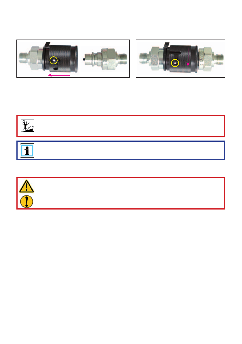
5.2 Coupling the quick-disconnect couplings
The device is connected to the hydraulic pump without risk of misconnection using
monocoupling halves (female and male coupling).
X
Y
Before coupling, remove dust caps and then pull back and hold the locking sleeve of the
female coupling half (position X). Connect the male and female couplings and release the
locking sleeve. Then turn the locking sleeve to position Y. The connection has been made
and locked. Uncoupling is done in the reverse order. Coupling of the devices is only possible,
when the hoses are depressurised. For dust protection, the supplied dust caps must be
refi tted.
ATTENTION!
Always connect the return line fi rst and then the supply line!
NOTE:
Coupling of the devices is only possible, when the hoses are depressurised.
For dust protection, the supplied dust caps must be refi tted.
WARNING / CAUTION / ATTENTION!
Some quick-disconnect couplings have special functions.Therefore, you must
not unscrew them from the hoses or swap them over!
11
Page 12
6. Operation
6.1 Setting up the LUKAS traversing system
6.1.1 General
The LUKAS traversing system consists of several individual components. Appropriate
combination of the individual components can be used to set up various different total
systems. With some of these overall systems, not all the individual components are required,
and on others you will need several of the individual components.
In addition to the individual components of the LUKAS traversing system, suitable hydraulic
cylinders will be required for lifting the load and at least one suitable hydraulic power pack or
a suitable hand pump will be needed to provide the pressure.
6.1.2 Basic work required for setting up the traversing system
CAUTION / ATTENTION!
Prior to setting up the individual components of the LUKAS traversing system,
the load to be lifted must be secured against slipping as prescribed in the
respective applicable guidelines and regulations. The relevant rerailing concepts
of the vehicle manufacturer must be observed.
Before setting up the traversing system, check the individual components for visible damage.
You must always take into account the following when setting up the components of the
traversing system:
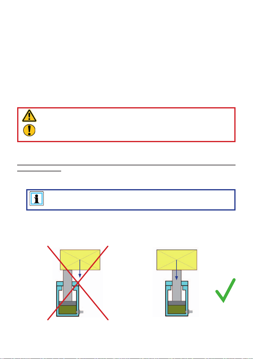
- Please ensure that the load is applied centrally to the piston rod or rolling carriage plate.
NOTE:
Select the more favourable load grip point in order to guarantee maximum
safety!
Position the cylinder/rolling carriage underneath the centre of gravity of the load, such
that the load cannot tip over during lifting and endanger the operating staff or the
equipment being used. The load should always act centrally on the piston surface or the
surface of the rolling carriage plate. Avoid lateral forces acting on the cylinder!
Frequently it is not possible to apply the load on the full cylinder surface. LUKAS also
Load
WRONG RIGHT
12
Load
Page 13
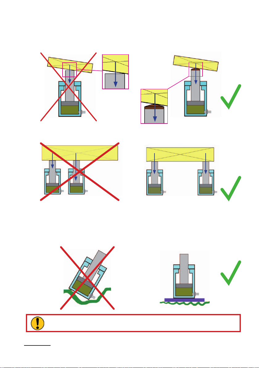
recommends the use of suitable piston guard plates for this reason, as otherwise there is
a risk of damage to the piston rod or the cylinder. A convex piston guard plate distributes
the load evenly over the piston area again.
If several cylinders/rolling carriages are used simultaneously, the load should be
distributed as evenly as possible over all cylinders/rolling carriages.
Load
WRONG
The following must always be observed when installing the cylinders:
Load
share 1
Load proportion 1 < Load proportion 2
WRONG RIGHT
- non-slip and even ground, so that the entire base area of the cylinder is in contact with
the ground. If there is any doubt as to the load-bearing capacity of the ground, suitable
wooden or metal underplates (blocks) must be used to increase the contact area.
- The area of support must be a continuous level surface (not a grating, gravel etc.)
Load
share 2
Load
share 1
Load proportion 1 = Load proportion 2
Load
RIGHT
Load
share 2
WRONG
ATTENTION!
Hydraulic fl uids may produce a lubricating fi lm on the ground!
- Never place cylinders on a yielding underplate
- Never use cylinders without a piston guard plate, in order to avoid damage to the piston
13
RIGHT
Page 14
and achieve safe power introduction
- Please ensure that the load is applied centrally to the piston rod.
- Stability and load application is improved if you use load distribution plates. Distribution
plates permit an angle of inclination of 5 °.
ATTENTION!
Observe the permissible angle of inclination when lifting the vehicle!
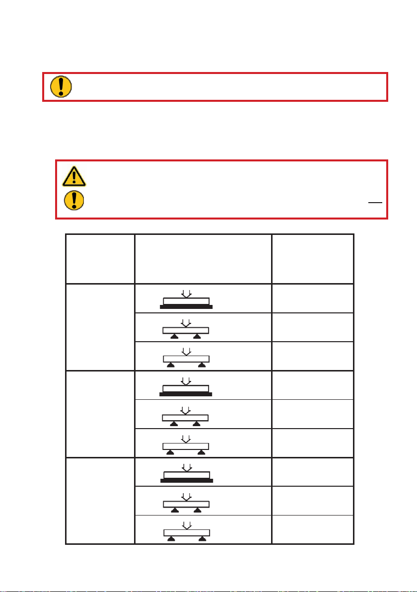
6.1.3 Setting up the rerailing bridges
The bridge is placed across the tracks and carefully supported by wooden planks. Please
observe that:
- The rerailing bridge and the supporting wooden beam packers are on a non-defl ecting
fi xed subsurface.
CAUTION / ATTENTION!
When using wooden underplates, care must be taken that particularly
hard wood without damage is used, so that the underplate cannot crack.
Strapping additional pieces of wood together with metal bands is not
suffi cient!
- The maximum load of the bridge is not exceeded. See the following table.
Bridge height Support width Max. load
[mm] [m] [kN]
[in.] [ft.] [lbs.]
85 0 350
3.35 0 787000
140 0 1000
5.51 0 225000
184 0 1200
7.24 0 270000
*
*
160
3.28 13500
1.43 50
4.69 11200
*
*
1 500
3.28 112000
1.43 400
4.69 90000
*
*
1 900
3.28 202000
1.43 650
4.69 146000
* completely packed up
14
Page 15
- The maximum load of the bridge connecting elements (optional) is not exceeded:
Bridge height Support width Max. load
[mm] [m] [kN]
[in.] [ft.] [lbs.]
85 1 20
3.35 3.28 4500
140 1 200
5.51 3.28 45000
184 1 300
7.24 3.28 68000
- the bridge is horizontally aligned:
The angle of the bridge may not exceed 3°.
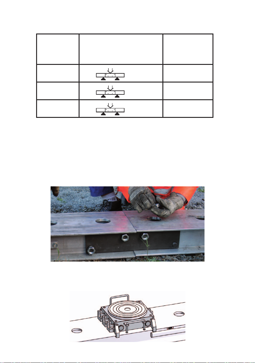
If one bridge is not long enough, a second bridge can be screwed on by means of joining
elements.
This done by placing the ends of the rerailing bridges together and bolting them together
using fl at steel plates, bolts, washers and nuts (as shown in the illustration below). You must
ensure that the top running surfaces of the rerailing bridges are not offset to each other
axially, since otherwise proper movement cannot be guaranteed and/or this can lead to
damage to the individual components.
6.1.4 Setting up the rolling carriages
The rolling carriages are mounted on the rerailing bridges in such a way that the rollers of
the rolling carriages can move along the rerailing bridges. The guides on the rolling carriages
prevent it from slipping off the rerailing bridge to the side.
15
Page 16

6.1.5 Setting up hydraulic cylinders on the rolling carriages
The hydraulic cylinders are placed centrally on the top carrier plate of the rolling carriage if
they are to be moved along with the lifted load (see illustration below).
CAUTION / ATTENTION!
When traversing a load lifted by a hydraulic cylinder (upright on the rolling
carriage), you need to ensure that the load cannot tip over during traversing.
Loads are more safely traversed by lifting them externally by hydraulic cylinders,
then placed on the rolling carriage and only then traversed.
ATTENTION!
When commissioning you must observe all the instructions and regulations in the
separate operating instructions for the cylinders being used!
NOTE:
We recommend using a foot-plate from the LUKAS accessories programme if
you wish to traverse a hydraulic cylinder standing on the rolling carriage. The
foot-plates provide assistance in providing a solid base for the cylinder and by
counteracting the tip movement during traversing. The foot-plate must always
be fully packed-up when in use.
16
Page 17

6.1.6 Setting up the traversing cylinder with fi xed anchor pin
Insert the traversing cylinder with the fi xed anchor pin in one of the suitable mounts (slotted
holes) in the rerailing bridge, and hook it into the middle mount for the rolling carriage with
the piston rod head (see illustration below). It may be necessary to move the rolling carriage
slightly to allow the cylinder head to be hooked in.
NOTE:
The LUKAS traversing system must be set up in consideration of the
traversing device and the traversing distance.
17
Page 18

6.1.7 Setting up the traversing cylinder with anchor cylinder (double-acting)
Insert the traversing cylinder with the head of the anchor cylinder in one of the matching
mounts in the rerailing bridge. To do this you must slide the slide plate at the back end of the
traversing cylinder upwards slightly . Then suspend the traversing cylinder with the piston rod
head in the middle mount in the rolling carriage (see illustration below). It may be necessary
to move the rolling carriage slightly to allow the cylinder head to be hooked in.
18
Page 19

Now pull the slide plate upwards to the stop and apply the guide plates on the right and left
on the traversing cylinder.
Move the applied guide plates towards the cylinder head and slide the slide plate back down.
The traversing cylinder is now secured against lateral traversing and against lifting.
19
Page 20

6.1.8 Setting up and adjusting the connecting rods
The distance between the load lift points must be set precisely using the connecting rods.
For this reason you have a coarse and fi ne adjustment facility.
Coarse setting of the connecting rods:
1. Remove the locking pin.
2. The coupling rod can now be pulled out and this allows coarse setting of the distance of
the rolling carriages. The hole in the coupling rod must line up with a hole in the pipe in
order to be able to insert the locking pin.
3. Insert the locking pin back into the relevant hole in the pipe.
20
Page 21

Fine setting of the connecting rods:
The fi ne setting is carried out at the other end of the pipe. Insert a metal rod (ø8 mm) or a
similar tool into the cross-hole of the adjusting bolt and unscrew it (anticlockwise), until the
desired distance is reached. The adjusting bolt can be unscrewed maximum 80 mm in order
to carry out the fi ne adjustment.
Connecting two rolling carriages:
Two connecting rods are always required for connecting two rolling carriages. These two
connecting rods must be set to the same length. They are inserted in the mounts provided
in the rolling carriages with the coupling rod on one side and the adjusting bolt on the other
side.
21
Page 22

NOTE:
If the traversing cylinder is to operate between the two rolling carriages, then
the connecting rods must be mounted only after setting up the traversing
cylinder.
6.1.9 Examples of traversing systems
CAUTION / ATTENTION!
If there is any doubt about the set-up of your traversing system you must contact
a relevantly trained safety expert or LUKAS direct.
NOTE:
When setting up the traversing cylinder in combination with two rolling carriages
there are two set-up possibilities:
1. The traversing cylinder is set up between the connecting rods of the rolling
carriages.
2. The traversing cylinder is set up outside the connected rolling carriages.
22
Page 23

The following gives a few examples of setting up of the traversing system:
1. Traversing system with a rolling carriage and separate load lifting
(recommended variant)
Components required:
- 1 Hydraulic power pack
- 1 Control table
- Separate load lifting system
(e.g. Hydraulic cylinder with required
accessories)
- Rerailing bridge
- 1 Rolling carriage
- 1 Traversing cylinder
- Packing material (e.g. hardwood beams)
- Hose lines
2. Traversing system with two rolling carriages and separate load lifting
(recommended variant)
Components required:
- 1 Hydraulic power pack
- 1 Control table
- Separate load lifting system (e.g. hydraulic cylinder with necessary accessories)
- Rerailing bridge
- 2 Rolling carriage
- 1 Traversing cylinder
- 2 Connecting rods
- Packing material (e.g. hardwood beams)
- Hose lines
Example illustration single point lifting
23
Page 24

Example illustration two point lifting
3. Traversing system with a rolling carriage and hydraulic cylinder standing on it
Components required:
- 1 Hydraulic power pack
- 1 Control table
- 1 Rolling carriage
- 1 Traversing cylinder
- 1 Hydraulic cylinder
- Packing material (e.g. hardwood beams)
- Hose lines
4. Traversing system with two rolling carriages and hydraulic cylinders standing on them
Components required:
- 1 Hydraulic power pack
- 1 Control table
- 2 Rolling carriage
- 1 Traversing cylinder
- 2 Hydraulic cylinder
- Packing material (e.g. hardwood beams)
- Hose lines
24
Page 25

6.2 Start-up
ATTENTION!
During commissioning you must observe all the instructions and regulations from
the separate operating instructions for all the components that you use in the
rerailing system that is to be commissioned!
Work required before commissioning:
Before commissioning you must carry out a visual check for damage and leaks on all
components being used. Damaged components must not be used and must be replaced!
The hydraulic components must be bled to remove air before commissioning!
Bleeding the traversing cylinder:
Before commissioning and following repairs, the equipment must be deaerated.
- Connect the equipment to the hydraulic pump (see chapter “Connecting the equipment”).
- Fully extend and retract the device several times without load.
NOTE:
We recommend that during the bleeding, the attached unit for the hydraulic
supply should stand at a higher level than the cylinder.
The connections on the hydraulic cylinder should face upwards.
Commissioning:
CAUTION / ATTENTION!
Secure the vehicle to be rerailed in accordance with the regulations to prevent its
rolling away, slipping and tipping over!
Set up all the components to be used as described in the Chapter "Setting up the LUKAS
traversing system". When setting up you must comply with all the applicable standards,
guidelines, regulations and statutes!
The separate hydraulic supply and the control of the LUKAS traversing system must be
outside the danger area!
Then connect all the hydraulic components as described in the Chapter "Connecting the
hydraulic equipment".
25
Page 26

CAUTION / ATTENTION!
Make sure that there are no persons remaining in the danger area!
Observe the individual rerailing concepts of the vehicle manufacturer.
Only then should you commission the rerailing system!
6.3 Controlling the LUKAS traversing system with anchor pin
CAUTION / ATTENTION!
The vehicle ton be rerailed must be secured against rolling away, slipping and
tipping over in accordance with the regulations!
NOTE:
You should note that the traversing distance of the cylinder is limited by its
piston stroke!
Depending on the location of the rolling carriages it may be that, under certain
circumstances, the full traversing distance is only achieved during the second
traversing procedure.
6.3.1 Traversing with external load lifting:
Procedure:
1. Set up the rerailing system as described in the Chapter "Setting up the LUKAS traversing
system" and the separate operating instructions of the additional LUKAS components
being used.
2. Lift the vehicle with the separate LUKAS load lifting system.
3. Place suitable support material (e.g. hardwood beams or metal plates) on the rolling
carriages and align the rolling carriages in such a way that the vehicle has a stable and
safe location after being put down.
CAUTION / ATTENTION!
The vehicle to be rerailed must be safely lifted up before packing up and
aligning to prevent it from slipping away or tipping over.
When packing up and aligning always also take account of the lifted vehicle!
If the vehicle should start to move in an uncontrolled manner you should
leave the danger area as quickly as possible!
After packing up and aligning you must leave the danger area!
4. Place the vehicle on the rolling carriage.
5. Move the traversing cylinder using the control table until the end point of the traversing
procedure is reached. If necessary, move the traversing cylinder.
It is strictly prohibited to work under loads suspended
exclusively by hydraulic means!
6. Move your separate LUKAS load lifting system so that the vehicle to be rerailed can be
lifted safely again. The vehicle must remain secured against rolling away, slipping and
tipping over!
7. Lift the vehicle to be rerailed and remove the support material from the rolling carriages.
8. Retract the traversing cylinder again.
26
Page 27

9. Put the vehicle down with the separate LUKAS load lifting system.
NOTE:
If the traversing movement of the rerailing bridge is not adequate, the entire
traversing system is relocated. When assembling the traversing system for
the fi rst time, make sure that allthe required preconditions in the Chapter
"Setting up the LUKAS traversing system" are fulfi lled!
You can then repeat the procedures 1 to 9.
10. Then remove the components of the traversing system being used again.
6.3.2 Traversing with the rolling carriages carrying the hydraulic cylinder(s):
Procedure:
1. Set up the rerailing system as described in the Chapter "Setting up the LUKAS traversing
system" and the separate operating instructions of the additional LUKAS components
being used.
2. Lift the vehicle with the hydraulic cylinder (the hydraulic cylinders) so that this cannot tip
over or slip away.
CAUTION / ATTENTION!
The use of a step set in combination with the hydraulic cylinder standing on
the rolling carriage is strictly prohibited!
3. Move the traversing cylinder using the control table until the end point of the traversing
procedure is reached.
NOTE:
Y ou should note that the traversing distance of the cylinder is limited by its
piston stroke!
Depending on the location of the rolling carriages it may be that, under
certain circumstances, the full traversing distance is only achieved during
the second traversing procedure.
It is strictly prohibited to work under loads suspended
exclusively by hydraulic means!
4. Put the vehicle down by retracting the hydraulic cylinder on the rolling carriage.
The vehicle must remain secured against rolling away, slipping and tipping over!
5. Remove the hydraulic cylinder(s) from the rolling carriage(s).
6. Retract the traversing cylinder(s) again.
NOTE:
If the traversing movement of the rerailing bridge is not adequate, the entire
traversing system is relocated. When assembling the traversing system for
the fi rst time, make sure that allthe required preconditions in the Chapter
"Setting up the LUKAS traversing system" are fulfi lled!
You can then repeat the procedures 1 to 9.
27
Page 28

7. Then remove the components of the traversing system being used again.
6.4 Controlling the DUO traversing cylinder with anchor cylinder
CAUTION / ATTENTION!
The vehicle ton be rerailed must be secured against rolling away , slipping and
tipping over in accordance with the regulations! Observe the individual rerailing
concepts of the vehicle manufacturer.
6.4.1 Traversing with external load lifting:
Procedure:
1. Set up the rerailing system as described in the Chapter "Setting up the LUKAS traversing
system" and the separate operating instructions of the additional LUKAS components
being used.
2. Lift the vehicle with the separate load lifting system.
3. Place suitable support material (e.g. hardwood beams or metal plates) on the rolling
carriages and align the rolling carriages in such a way that the vehicle has a stable and
safe location after being put down.
CAUTION / ATTENTION!
The vehicle to be rerailed must be safely lifted up before packing up and
aligning to prevent it from slipping away or tipping over.
When packing up and aligning always also take account of the lifted vehicle!
If the vehicle should start to move in an uncontrolled manner you should
leave the danger area
as quickly as possible!
After packing up and aligning you must leave the danger area!
4. Place the vehicle on the rolling carriage(s).
5. Secure the load against slipping away to the side.
6. Move the traversing cylinder until the end point of the traversing procedure is reached.
If the traversing distance of 280 mm between a pair of slotted holes is inadequate you
need to relocate the traversing cylinder. If the traversing distance is inadequate then
continue with Item 11.
7. In order to relocate you must move the traversing cylinder to the middle of the slotted
hole in order to guarantee ease of movement of the retracting/extending anchor cylinder.
Now retract the anchor cylinder.
8. Now move the traversing cylinder to the middle of two holes.
9. Then extend the anchor cylinder again and move the traversing cylinder until the anchor
cylinder engages again.
Without engaging in the slotted hole the rolling carriage may need to be secured against
rolling away if it is not aligned horizontally, in order to prevent inadvertent movement of
the vehicle to be rerailed!
After engaging, the rolling carriages move in the direction of the traversing movement of
the traversing cylinder.
10. Items 7 to 9 can be repeated "as often as you need".
NOTE:
The traversing movement is only limited by the length of the rerailing
bridge.
28
Page 29

CAUTION / ATTENTION!
When traversing several times make sure that the rolling carriages are not
pushed by the rerailing bridge!
1 1. Move your separate load lifting system for putting down so that the vehicle to be rerailed
can be lifted safely again. If it is not aligned horizontally, you must secure the rerailing
bridge against rolling away, slipping and tipping over, in order to prevent inadvertent
movement of the vehicle to be rerailed!
12. Lift the vehicle to be rerailed and remove the support material from the rolling carriages.
13. Put the vehicle down on the track with your separate load lifting system.
14. Move the traversing cylinder back into the start position.
15. Then remove the components of the traversing system being used again.
6.4.2 Traversing with the rolling carriages carrying the hydraulic cylinder(s):
Procedure:
1. Set up the rerailing system as described in the Chapter "Setting up the DUO traversing
system" and the separate operating instructions of the additional components being
used.
2. Lift the vehicle with the hydraulic cylinder (the hydraulic cylinders) so that this cannot tip
over or slip away.
CAUTION / ATTENTION!
The use of a step set in combination with the hydraulic cylinder standing on
the rolling carriage is strictly prohibited!
3. Move the traversing cylinder until the end point of the traversing procedure is reached.
If the traversing distance of 280 mm between a pair of slotted holes is inadequate you
need to relocate the traversing cylinder.
4. In order to relocate you must move the traversing cylinder to the middle of the slotted
hole in order to guarantee ease of movement of the retracting/extending anchor cylinder.
Now the anchor cylinder retracts.
6. Then extend the anchor cylinder again, causing it to lock the traversing unit again.
You should move the anchor cylinder to the middle of the slotted hole before locking/
unlocking, in order to guarantee ease of movement of the piston as it moves in and out.
Now move the traversing cylinder to the middle of two holes.
7. Without engaging in the slotted hole, the rolling carriage may need to be secured
against rolling away if the rerailing bridge is not aligned horizontally, in order prevent
inadvertent movement of the vehicle to be rerailed. Then extend the anchor cylinder
again and move the traversing cylinder until the anchor cylinder engages again. After
engaging, the rolling carriages move in the desired direction.
NOTE:
The traversing movement is only limited by the length of the rerailing
bridge or the overall length of the combined rerailing bridges.
29
Page 30

CAUTION / ATTENTION!
When traversing several times make sure that the rolling carriages are not
pushed by the rerailing bridge!
8. Items 6 and 7 can be repeated "as often as you need".
9. Put the vehicle down on the track by retracting the hydraulic cylinder standing on the
rolling carriage. The vehicle must remain secured against rolling away, slipping and
tipping over!
10. Remove the hydraulic cylinder(s) from the rolling carriage(s).
11. Retract the traversing cylinder again.
12. Finally remove the components of the traversing system being used.
7. Dismantling the equipment / deactivation following operation
WARNING / CAUTION / ATTENTION!
Before dismantling the rerailing equipment, please ensure that the moved load is
in a stable and fi rm position!
7.1 Hydraulic cylinder
After completion of the work, the hydraulic cylinders must be retracted leaving only a few
mm*) projecting. This relieves the hydraulic and mechanical stress on the equipment.
NOTE:
When hydraulic cylinders and traversing cylinders are in storage, fl uctuations in
ambient temperature can cause the pistons to move slightly. This phenomenon
is due to the difference in the expansion of the hydraulic fl uid enclosed on the
piston side and the rod side.
7.2 Hoses
First of all, decouple the pressure hose then the return hose as described in chapter
“Connecting the equipment”.
Ensure that you replace the dust protection caps onto the plug couplings.
ATTENTION!
The operating pressure in the system must be dissipated before uncoupling
the hoses.
*) 1 mm = 0.04 in.
7.3 Additional components of the traversing system
Removal of all components is carried out in the reverse order to the installation and is
described in the individual operating instructions of the components.
7.4 Hydraulic supply, control and separate load lifting systems
After completing the work, the hydraulic supply, control and any load lifting systems being
used must be stopped. See the separate instruction manuals for these components!
30
Page 31

8. Maintenance and service
A visual inspection must be carried out after every use, but at least once a year . Every 3 years,
or if there is any doubt regarding the safety or reliability of the equipment, a functional test
must also be performed. (Please also observe the relevant valid national and international
regulations pertaining to service intervals of hydraulic equipment).
ATTENTION!
Clean off any dirt before checking the equipment!
WARNING / CAUTION / ATTENTION!
To perform maintenance and repairs, personal protection equipment
appropriate for the work is an absolute requirement.
Inspections to be carried out:
Visual Inspection
• Cylinder and piston rod undamaged and not deformed,
• Cylinder accessories (e.g. piston protection plate) present and undamaged
• Rerailing bridge free from damage and deformation
• Connecting rods free from damage and deformation
• Rolling carriages free from damage and deformation
• General tightness (leaks),
• Handles present and securely bolted in place,
• All screwed connections tight
• Type plate, warning signs and other markings present and legible,
• Couplings must be easy to couple,
• Dust protection caps must be available,
• All accessories used not damaged
Functional test
• Piston stroke can be moved over full range inwards and outwards,
• Flawless and smooth extension and retraction of cylinders when pressurised.
• Rolling carriage moves perfectly without load.
• Connecting rods can be moved over full range inwards and outwards
• No unusual noises
9. Repairs
9.1 General information
Service work may only be performed by the device manufacturer or by personnel trained by
the device manufacturer and authorised LUKAS dealers.
Only genuine LUKAS spare parts in the spare parts list must be used on all components. It
is also imperative to take account of any special tools required, assembly instructions, safety
aspects (also observe the Chapter "Care and Maintenance"). During the assembly work,
pay particular attention to the cleanliness of all components because dirt can damage
the equipment!
WARNING / CAUTION / ATTENTION!
Protective clothes must be worn when repairs are being carried out,
since the devices may also be pressurised when not in operation.
31
Page 32

NOTE:
You should always contact LUKAS or an authorised dealer before using
couplings from another manufacturer.
ATTENTION!
Because LUKAS devices are designed for the highest performance, only
components may be replaced that are listed in the spare parts lists of the
corresponding device.
Other components in the device may only be replaced if:
- You have participated in an appropriate LUKAS service training course.
- You have the express permission of LUKAS Customer Service (after request,
verifi cation that permission may be granted. An examination in each individual
case is necessary!)
9.2 Preventative service
9.2.1 Care instructions
The exterior of the equipment is to be cleaned from time to time in order to protect it from
external corrosion. Oil is to be applied to the metallic surfaces.
9.2.2 Function and load test
If there is any doubt regarding the safety or reliability of the equipment, a function and load
test must also be performed.
9.2.3 Changing the hydraulic fl uid in the traversing and anchor cylinders
- After approx. 200 deployments, but after three years at the latest, replace the hydraulic
fl uid.
ATTENTION!
Always perform the change of the hydraulic fl uid over a collection tank and
dispose of the collected fl uid in a proper manner!
ATTENTION!
The hydraulic fl uid must be completely replaced if the application conditions
(ambient temperatures) change substantially. When selecting a suitable
hydraulic fl uid, please refer to chapter “Hydraulic fl uid recommendations”.
Procedure:
1. Completely retract the cylinder.
2. Unscrew the hoses from the cylinder,
3. Drain off the hydraulic fl uid,
4. Flush,
5. Refi t the hoses correctly,
6. Connect the pump (hydraulic power pack) with new hydraulic fl uid and move the cylinder
in and out several times,
7. Bleed the cylinder as described in the Chapter "Commissioning",
8. Disconnect the pump (hydraulic power pack) again.
32
Page 33

9.3 Repairs
9.3.1 Coupling replacement
The couplings must be replaced if:
- there is external damage,
- the locking does not function,
- hydraulic fl uid continues to leak in the coupled/uncoupled state.
WARNING / CAUTION / ATTENTION!
Never repair couplings: they must be replaced by genuine LUKAS parts!
During assembly tighten the coupling to a torque of M
= 40 Nm.
A
Procedure:
1. Remove the coupling.
2. Place a new coupling in position and tighten to a torque of M
= 40 Nm.
A
9.3.2 Replacing the handles on the rerailing bridge
Any damaged or broken handles must be replaced.
Procedure:
1. Pull the damaged handle out almost to the stop.
2. Release the locking pins by pulling the metal rings back until the pins can be removed.
3. You can now remove the handle from the rerailing bridge and replace it.
4. Assembly is in the reverse order.
Securing pin
HandleHandle
9.3.3 Replacing the handles
on rolling carriages
All damaged or broken handles
must be replaced.
Procedure:
1. Release the screws on the handle and
remove them.
2. You can now remove the handle from
the rolling carriage and replace it.
3. Assembly is in the reverse order.
Handle
Bolts
33
Page 34

9.3.4 Replacing the handles on traversing cylinder
Any damaged or broken handles must be replaced.
Procedure for fi xing directly on the traversing cylinder:
1. Release the screws on the handle and remove them, together with the washers
underneath.
2. You can now remove the handle and replace it.
3. Assembly is in the reverse order.
Bolt
Bolt
Washer
Washer
Handle
Procedure for fi xing with clamps:
1. Release the screws and nuts and remove them.
2. Y ou can now remove the handle and the associated washers from the traversing cylinder
and replace them. If there is damage to the clamps remove them towards the cylinder
head. Make sure not to damage the hoses
3. Assembly is in the reverse order.
Handle
Washers
Bolts
Clamps
Nuts
34
Page 35

9.3.5 Slider plate replacement on the traversing cylinder with anchor cylinder
A damaged, bent or broken slider plate must be replaced.
Procedure:
1. Release the screws on the anchor cylinder and remove them.
2. You can now remove the slider plate and replace it.
3. Assembly is in the reverse order. Make sure that the pin mounted in the anchor cylinder
can move in the narrow slotted hole of the slider plate.
Pin
Narrow
slotted
hole
Bolts Slider plate
9.3.6 Replacing the hoses on traversing cylinder
Any damaged or leaking hoses must be replaced.
Procedure:
1. Unscrew the defective hoses at the cylinder and remove them, together with the seal
rings underneath.
NOTE:
If just the hoses are defective, not the couplings, you must fi rst unscrew the
couplings before removing the hoses. After replacing the hoses these are
mounted on the new hoses (see Chapter "Changing the couplings").
2. Place the seal rings on the hose connections of the cylinder and screw the new hoses in
place. (Observe the tightening torque of M
= 35 Nm)
A
9.3.7 Decals
All damaged and/or illegible decals (safety notices, type plate etc.) must be replaced.
Procedure:
1. Remove damaged and/or illegible decals.
2. Clean surfaces with acetone or industrial alcohol.
3. Affi x new decals.
When affi xing take care to position the decals in the correct location. If this is no longer
known, you should ask your authorised dealer or contact LUKAS directly.
35
Page 36

Fault Check Cause Solution
Cylinder piston moves
slowly or jerkily when
activated
10. Troubleshooting
Are the hoses
connected
properly?
Does the pump unit
work?
Pressure in control
table OK? Read
the pressure gauge
Air in the
hydraulic system
Bleed the pump system
(see operating instructions
for hydraulic power packs)
Bleeding/depressurising
the control table (actuating
the pressure relief valves
etc., see Control Table
operating instructions)
Device doesn’t
perform at its given
power
Hoses cannot be
coupled
Hydraulic fl uid leak
on the hoses or the
fi ttings
Visual check of
hydraulic oil
Hydraulic fl uid level
in the supplying
pump adequate?
Check operating
pressure of driving
hydraulic unit
Check device Device defective Remove the device from
Are the hoses
defective?
Hydraulic oil too
viscous because
of ambient
temperature.
Insuffi cient
hydraulic fl uid in
the pump
Pressure supply
has too low
pressure
Pressurized Set hydraulic pump to
Coupling
defective
Leak, possible
damage
Replace the hydraulic oil
by oil with the relevant
viscosity
Top up hydraulic fl uid,
deaerate
If possible, increase
max. operating pressure
on the hydraulic unit to
max. operating pressure
of the cylinder or use
another hydraulic unit with
suffi cient max. operating
pressure.
service and repair it (have
it repaired)
pressureless circulation
Coupling must be replaced
immediately
Replace hoses
36
Page 37

Fault Check Cause Solution
Damage on the
surface of the
hydraulic hose lines
Hydraulic fl uid leaks
on the piston rod
Mechanical
damage or
contact with
aggressive
agents
Defective rod seal Repair by an authorised
Damage to the
piston
Replace hoses
dealer, by personnel
specially trained by
LUKAS, or by LUKAS itself
Leak from the
couplings
Contact an authorised LUKAS dealer or the LUKAS Customer Service Department directly
if the malfunctions cannot be rectifi ed.
The address for the LUKAS Customer Service department is:
LUKAS
Weinstrasse 39, D-91058 Erlangen, Germany
PO Box 2560 D-91013 Erlangen
Tel.: (+49) 09131 / 698 - 348
Fax.: (+49) 09131 / 698 - 353
Hydraulik GmbH
Is the coupling
damaged?
Coupling
defective
Coupling must be replaced
immediately
37
Page 38

11. Technical data
Because all values are subject to tolerances, there may be small differences between the
data for your device and the data in the following tables!
11.1 Traversing cylinder
Device type TC170 90-350F Value Units Remarks
Item number 70-30-20
Dimensions l x w x h 653 x 156 x 177 mm retracted
25.7 x 6.2 x 6.9 in.
Length, extended 973 mm
38.3 in.
Force / Pushing 176 kN
39600 lbf.
Force / Pulling 92 kN
20700 lbf.
Stroke Total 320 mm
12.6 in.
Operating pressure max. 53 MPa
7700 psi
Volume of hydraulic
fl uid
509 cm³
31.1 cu.in.
Ambient
-20 … +55 °C
temperature
-4 … +131 °F
Weight 24 kg including hydraulic
fl uid
52.9 lbs.
Specifi cation of
hydraulic fl uid
Locking / Unlocking
* 1 MPa = 10 bar
** Necessary volume of hydraulic fl uid in the hydraulic unit to operate the unit
(differential volume on piston / rod side)
HM 10 ISO
6743-4
manual
38
Page 39

Device type TC170 90-350 Value Units Remarks
Item number 70-30-10
Dimensions l x w x h 668 x 363 x 197 mm retracted
26.3 x 14.3 x 7.7 in.
Length, extended 988 mm
38.9 in.
Force / Pushing 176 kN
39600 lbf.
Force / Pulling 92 kN
20700 lbf.
Stroke
Total 320 mm
12.6 in.
Operating pressure
max. 53 MPa
7700 psi
Volume of
hydraulic fl uid
509 cm³
31.1 cu.in.
Ambient
temperature -20 … +55 °C
-4 … +131 °F
Weight
25 kg
including hydraulic
fl uid
55.1 lbs.
Specifi cation of
hydraulic fl uid
HM 10 ISO 6743-
4
Locking /
Unlocking
Hydraulic
* 1 MPa = 10 bar
** Necessary volume of hydraulic fl uid in the hydraulic unit to operate the unit
(differential volume on piston / rod side)
39
Page 40

Device type TC170 200-350 Value Units Remarks
Item number 70-30-30
Dimensions l x w x h 685 x 370 x 214 mm retracted
27.0 x 14.6 x 8.4 in.
Length, extended 1007 mm
39.7 in.
Force / Pushing 337 kN
75800 lbf.
Force / Pulling 207 kN
46500 lbf.
Stroke Total 322 mm
12.7 in.
Operating pressure max. 53 MPa
7700 psi
Volume of hydraulic
fl uid 793 cm³
48.4 cu.in.
Ambient
temperature -20 … +55 °C
-4 … +131 °F
Weight
44 kg
including hydraulic
fl uid
97 lbs.
Specifi cation of
hydraulic fl uid
Locking / Unlocking
Hydraulic
HM 10 ISO
6743-4
* 1 MPa = 10 bar
** Necessary volume of hydraulic fl uid in the hydraulic unit to operate the unit
(differential volume on piston / rod side)
40
Page 41

11.2 Rolling carriage
Device type RC-700/350 RC-1000/350
Item number 840720640 840721631
Dimensions
(L x B x H)
max. width of
rerailing bridge
max. permitted
load
Weight
[mm] 390 x 380 x 130 360 x 380 x 154
[in.] 15.4 x 15 x 5.12 14.2 x 15 x 5.5
[mm] 350 350
[in.] 13.8 13.8
[kN] 750 1000
[lbf.] 168600 224800
[kg] 41.5 62
[lbs.] 91.7 139
11.3 Rerailing bridges
Device type 1.1 m / 85 mm 2.2 m / 85 mm 3.3 m / 85 mm
Item number 840726391 840725792 840725093
Dimensions
(L x B x H)
Weight
[mm] 1100 x 350 x 85 2200 x 350 x 85 3300 x 350 x 85
[in.] 43.3 x 13.8 x 3.35 86.6 x 13.8 x 3.35 130 x 13.8 x 3.35
[kg] 34 68 102
[lbs.] 75 15 225
Device type 1.1 m / 140 mm 2.2 m / 140 mm
Item number 840726350 840725750
Dimensions
(L x B x H)
Weight
Device type 3.3 m / 140 mm 4.4 m / 140 mm
Item number 840725050 840726550
Dimensions
(L x B x H)
Weight
[mm] 1100 x 350 x 140 2200 x 350 x 140
[in.] 43.3 x 13.8 x 5.5 86.6 x 13.8 x 5.5
[kg] 40 80
[lbs.] 88 176
[mm] 3300 x 350 x 140 4400 x 350 x 140
[in.] 130 x 13.8 x 5.51 173 x 13.8 x 55.1
[kg] 120 160
[lbs.] 265 353
41
Page 42

Device type 1.1 m / 184 mm 2.2 m / 184 mm
Item number 840726381 840726382
Dimensions
(L x B x H)
Weight
Device type 3.3 m / 184 mm 4.4 m / 184 mm
Item number 840726383 840726384
Dimensions
(L x B x H)
Weight
[mm] 1100 x 350 x 184 2200 x 350 x 184
[in.] 43.3 x 13.8 x 7.24 86.6 x 13.8 x 7.2
[kg] 70 140.5
[lbs.] 154 310
[mm] 3300 x 350 x 184 4400 x 350 x 184
[in.] 130 x 13.8 x 7.24 17.3 x 13.8 x 7.24
[kg] 211 281
[lbs.] 465 620
11.4 Connecting rods
Device type 1830/1030 2800/1500
Item number 840720571 840720575
Length(retracted)
Length(extended)
Dimensions
(diameter)
Weight
[mm] 1030 1500
[in.] 40.6 59.1
[mm] 1830 2800
[in.] 72.1 110
[mm] 65 50
[in.] 2.6 2
[kg] 40 58.5
[lbs.] 88 129
42
Page 43

11.5 Recommended hydraulic fl uids
Mineral oil DIN ISO 6743-4 for LUKAS hydraulic equipment
Oil temperature range Oil designation Viscosity rating Remarks
A -24 .... +30°C HL 5 VG 5
B -18 .... +50°C HM 10 VG 10
C -8 .... +75°C HM 22 VG 22
D +5 .... +80°C HM 32 VG 32
E -8 .... +70°C HF-E15 VG 15 Bio-oil
Oil temperature range Oil designation Viscosity rating Remarks
A
B
C
D +41.0 .... +176°F HM 32 VG 32
E
-11.2 .... +86°F HL 5 VG 5
-0.4 .... +122°F HM 10 VG 10
+17.6 .... +167°F HM 22 VG 22
+17.6 .... +158°F HF-E15 VG 15 Bio-oil
recommended range of viscosity: 10...200 mm²/s
Supplied with HM 10 DIN ISO 6743-4.
(10…200 cSt.)
11.6 Operating and storage temperature ranges
Operating temperature [°C] -20 … +55
Ambient temperature (device in operation) [°C] -25 … +45
Storage temperature (device not in operation) [°C] -30 … +60
Operating temperature [°F] -4 … +131
Ambient temperature (device in operation) [°F] -13 … +113
Storage temperature (device not in operation) [°F] -22 … +140
43
Page 44

12. Declaration of conformity
44
Page 45

13. Notes
45
Page 46

46
Page 47

47
Page 48

Please dispose of all packaging materials and
removed items properly.
LUKAS
A unit of the IDEX Corporation
Hydraulik GmbH
Weinstrasse 39, D-91058 Erlangen, Germany
Tel.: (+49) 0 91 31 / 698 - 0
Fax.: (+49) 0 91 31 / 698 - 394
e-mail: lukas.info@idexcorp.com
www.lukas.com
Made in GERMANY
© Copyright 2014 LUKAS Hydraulik GmbHLUKAS_traversing_system_manual_143000085_en.indd
Subject to changes
 Loading...