

Page 1

LR510 Self Levelling Rotary Laser Level
USER GUIDE
®
Page 2

2
LR510
Lufkin LR510
Horizontal self-levelling by magnetically-dampened pendulum system, vertical alignment via
adjustable base. Laser 635 nm, accuracy 2 mm / 10 m, dust and splash protected to IP 54.
Self-levelling range, 3.5° with tilt alarm. For all horizontal and vertical alignment work. The
plumb up vertical reference beam is suitable for dropping a perpendicular line or for aligning
partition walls. The wall/floor bracket can be used to level the unit vertically or fasten it to a
wall.
General safety instructions
Caution: Never look directly into the beam. Lasers must be kept out of reach of children.
Never intentionally aim the device at people. This
is a quality laser measuring device and is 100%
factory adjusted within the stated tolerance. For
reasons of product liability, we must also draw
your attention to the following: Regularly check
the calibration before use, after transport and
after extended periods of storage. We also wish
to point out that absolute calibration is only possible in a specialist workshop. Calibration by
yourself is only approximate and the accuracy of the calibration will depend on the care with
which you proceed.
Warranty:
The warranty period is two years from the date of purchase. The warranty covers all material
and manufacturing defects occurring during this time. The following are excluded from
warranty: Damage due to improper use (e.g. connection to an unsuitable power source, falling
onto a hard surface, etc); improper storage; normal wear and tear; minor defects not impairing
operation. Any tampering by unauthorized persons will render the warranty void. In the event
that you need to claim warranty, please return the complete device together with proof of
purchase to the place of purchase or to the Service and Shipping address on the back page.
Note: This product is a precision instrument that must be handled and treated with care.
Avoid shocks and impact. Always keep and carry in the case! Switch all lasers off and secure
the pendulum when not in use. For cleaning, use a soft cloth and glass cleaner.
Laser light !
Do not stare into the
beam or view directly
with magnifiers.
Class 2 laser
EN60825-1:2007-10
Page 3
3
LR510
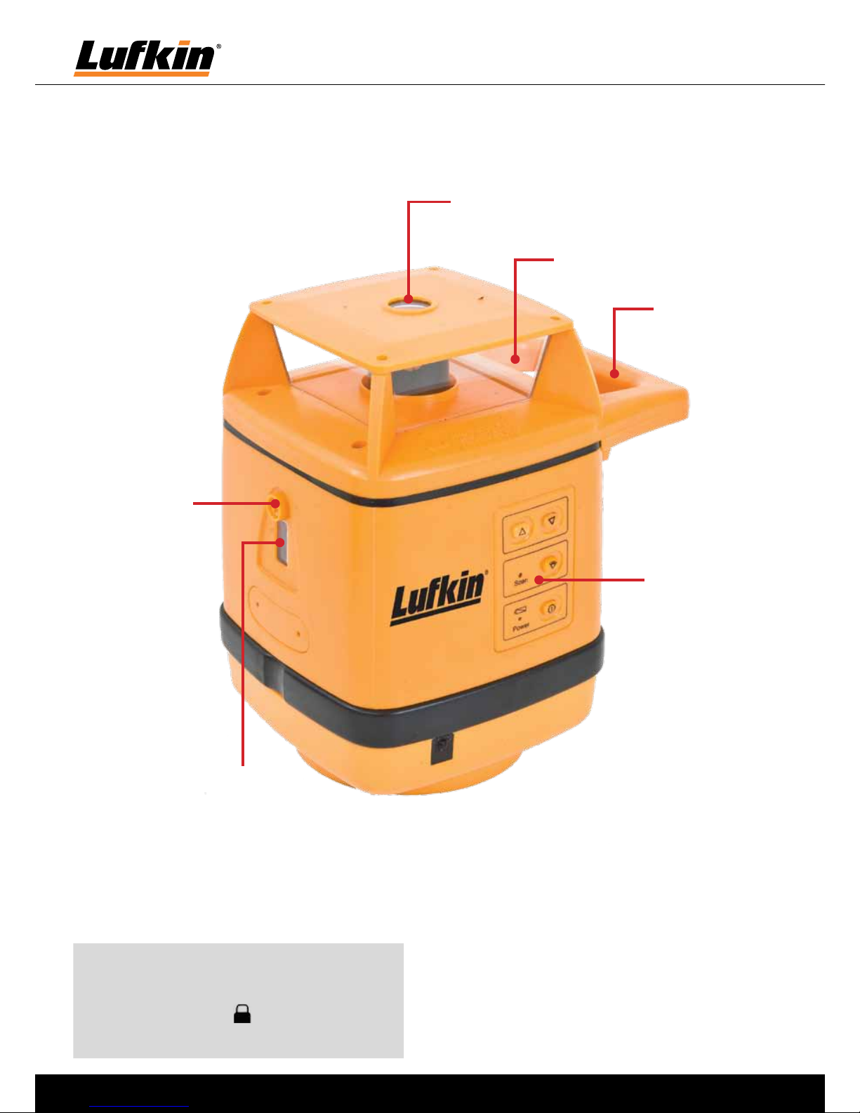
Note: During transport and in vertical
operation, make sure that the pendulum
lock is set to “lock” failure to do so
may result in damage to the device.
Plumb beam aperture
Rotating laser window
Carry handle
Control panel
Bubble
adjusting
point
Bubble for
vertical
operation
Page 4
4
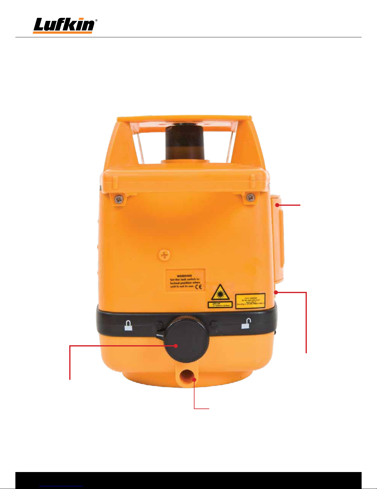
LR510
Vertical foot
recepticle used in
vertical operation
Pendulum Lock
Battery
cover
Charger / power
supply socket
Page 5

5
LR510
Horizontal use of LR510
• Set up the LR510 on a surface that is as level as possible or fasten it to a tripod.
• Turn the pendulum lock in the arrow’s “Unlock” direction to its limit. This releases the
locking mechanism that protects the pendulum during transport.
• Press the On/Off button.
• Within its range of +/- 3,5°, the LR510 will level itself automatically and the prism head will
begin to turn.
• The speed of rotation can be changed using the up & down buttons from 100 - 300 RPM.
Vertical use of LR510
• Turn the pendulum lock in the arrow’s “Lock” direction to its limit.
• Insert the vertical operatin foot into the vertical foot recepticle and adjust the foot untill the
vertical operation vial is centered between the centre markings.
• Press the On/Off button. The prism head will begin to rotate.
Note: Always unlock the pendulum lock when the LR510 is being used for horizontal
levelling by turning the transport lock to its “Unlock” position. If the unit is currently
outside of its automatic levelling range (> 3,5°) , a warning signal will sound and the
prism head will not rotate. The unit must then be placed on a surface which is closer to
level. When in vertical use, the unit does not level itself automatically.
Page 6

6
LR510
Control Panel:
On/Off button: push
the button to power
the laser on or off
Laser Speed & Scan
Direction Button:
In continuous rotation
mode: Reduce speed
In scan mode: Scan
range shifts counter
clock wise
Laser Speed & Scan
Direction Button:
In continuous rotation
mode: Increase speed
In scan mode: Scan
range shifts clock
wise
Scan mode button
SCAN MODE INDICATOR:
CONTINUOUS GLOW
indicates continuous
rootation
FLASHING indicates
scan
Power Indicator:
GLOWING indicates ON
NOT GLOWING indicates OFF
FLASHING indicates LOW VOLTAGE,
(recharge batteries)
Page 7

7
LR510
Laser Detector & Remote Control Unit:
Level reference grove
Laser
beam
receiver
Horizontal vial
Laser Detector
Remote Control Unit
On off switch
Off switchScan mode
Backlight
LCD
Hand receiver mode
Volume
Detector bracket
Laser Speed & Scan
Direction Button:
In continuous rotation
mode: Reduce speed
In scan mode: Scan
range shifts counter
clock wise
Laser Speed & Scan
Direction Button:
In continuous rotation
mode: Increase speed
In scan mode: Scan
range shifts clock
wise
Page 8

8
LR510
Gradient Mode:
• Turn the pendulum lock in the arrow’s “Lock”
direction to its limit. Now the tilt function
is inactive and the unit cannot align itself
automatically.
• Press the On/Off button. The prism head will
begin to rotate.
• The speed of rotation can be changed using
the up & down buttons.
• Adjust the unit to the desired angle. Slope
angle can be set precisely and quickly with
the aid of the optional tilt plate, Part No.:
LTP1
Important: Horizontal levelling cannot be accomplished in gradient mode because the
unit cannot automatically level itself.
Note:
Regularly check the calibration before use, after
transport and after extended periods of storage.
Always make sure to check all 3 axes.
Z
Y
X
X - / Y - / Z axes
Page 9

9
LR510
Operation of the LR510
• Open the battery compartment, insert the battery pack with the exposed metal ends of
the battery pack aligned with the + & - terminals (see pictures on right). Close the battery
compartment.
Charging the batteries
• Before using the LR510, fully charge the batteries.
• Connect the battery charger/mains unit to a mains
source and plug into the socket. Please only use the
charger/mains unit supplied with the device. If a different one is used, the warranty will become void.
• If the LED blinks constantly, either the batteries must
be exchanged or recharged.
Insertion of batteries in the detector
• Remove the battery cover (9) and insert the batteries as shown by the installation symbol,
ensuring that the polarity is correct. Then replace the cover.
• To extend battery life, the receiver switches off automatically after about 5 minutes if not
used.
Note: Do not expose batteries to excessive heat such as sunshine, fire, etc. Dry batteries
must not be recharged. Used batteries must not be disposed of as household waste.
Please take them to a collection point for used batteries or for special waste. Ask your
local authority for further details.
Page 10

10
LR510
LR510 Specifications
Self-levelling range ± 3.5° (horizontal)
Accuracy ± 3mm / 10m
Vertical levelling manual
Perpendicular reference beam 90° to rotation plane
Rotation speed 100 - 300 rpm
Laser wavelength 635 nm
Laser Class IIIA (EN60825-1:2007-10)
Laser output rating ≤ 5 mW
Rechargeable Batt. / batt. operating time approx. 20 h / 45 h, 4 x type AA
Battery recharging time approx. 14 h
Working temperature range -10°C - +40°C
Protection class IP 54
Weight 1.65 kg
Laser Receiver
Batteries / Power supply 4 x type AA
Battery life approx. 70 h
Laser reception range:
SensoLite 210
200m
Operating temperature 0°... 50°C
Storage temperature -10°C ... 70°C
Technical Specifications
Page 11

11
LR510
Calibration Check
To check the calibration of the LR510 Laser, place the Laser on a surface or preferably a tripod
approximately 10m from a wall or post with the control panel away from the wall or post.
1. Release the pendulum lock and switch on the Laser.
2. Mark the level point on the wall or post and label this point “A” using the detector.
3. Rotate the Laser on the surface or Tripod 180º. Be certain NOT to move or adjust the tripod. Mark
the level point on the wall or post and label this point “B”. You have now checked the “Y” axis.
The point half way between points “A” and “B” is true level. If “A” and “B” are 4mm apart or less then
no adjustment is required.
To check the “X” axis, rotate the level by 90º so that one of the sides is towards the wall or post.
4. Mark the level point on the wall or post and label this point “C”.
5. Rotate the Laser on the surface or Tripod 180º so that the other side is towards the wall or post. Be
certain NOT to move or adjust the tripod. Mark the level point on the wall or post and label this point
“D”. You have now checked the “X” axis. The point half way between points “C” and “D” is also true
level and should be the same as that noted for the “Y” axis above. If points “C” and “D” are 4mm apart
or less then no adjustment is required. To adjust the LSL160 remove the plastic cross recess screw in
the axis requiring adjustment. The “Y” axis is adjusted using a 2.5mm Allen key and adjust the “X” axis
screw using a 2mm straight blade screwdriver.
A
B
Max 4mm
1
A
2
B
C
D
Max 4mm
1
C
2
D
Note the maximum adjustment is 20mm so if more than this is required then return the
Laser to Apex Tool Group service dept.
Page 12

LR510 User guide issue: 12-04-03A
Limited Lifetime Guarantee
Apex Tool Group quality products are Guaranteed
against any defect in material or workmanship. Damage
caused by abuse, improper use or excessive wear is not
covered by this warranty.
This warranty is provided in addition to other rights
and remedies you have under law: Our goods come
with guarantees that cannot be excluded under
the Australian Consumer Law. You are entitled to a
replacement or refund for a major failure and for
compensation for any other reasonably foreseeable
loss or damage. You are also entitled to have the goods
repaired or replaced if the goods fail to be of acceptable
quality and the failure does not amount to a major
failure.
Claims should be returned, with proof of purchase, to
the place of purchase or returned prepaid to the address
below. Repaired or replacement goods will be returned
at our cost.
Apex Tool Group Pty Limited
519 Nurigong Street, Albury
NSW 2640, AUSTRALIA
Ph: (02) 60580300
[email protected]
www.apextoolgroup.com.au
 Loading...