

Page 1
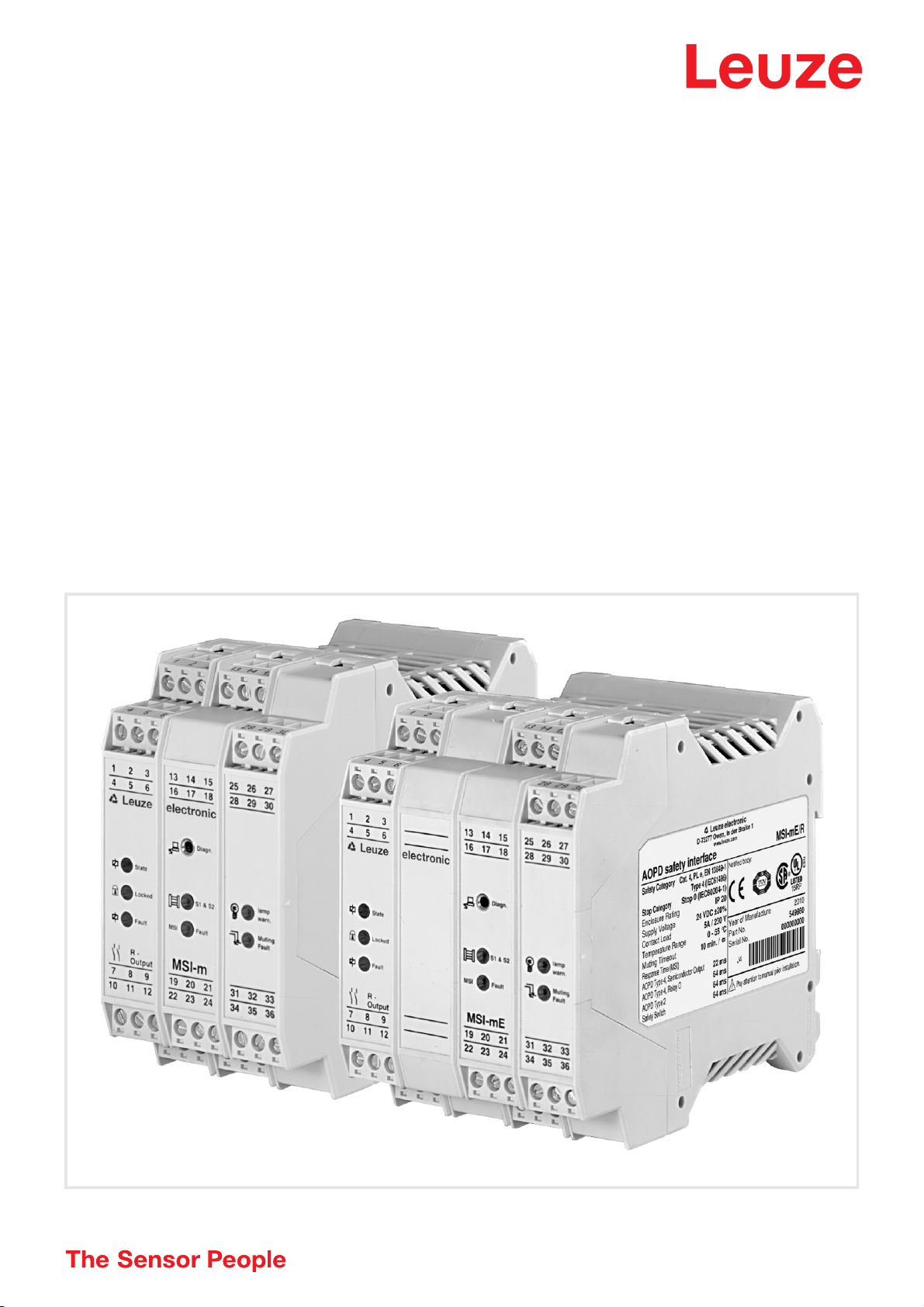
Original operating instructions
MSI-m/R
MSI-mE/R
Modular safety interface
We reserve the right to make technical changes
EN • 2020-07-22 • 603501
Page 2

© 2020
Leuze electronic GmbH & Co. KG
In der Braike 1
D-73277 Owen / Germany
Phone: +49 7021 573-0
Fax: +49 7021 573-199
http://www.leuze.com
info@leuze.com
Leuze electronic GmbH + Co. KG MSI-m(E)/R 2
Page 3

1 About this document . . . . . . . . . . . . . . . . . . . . . . . . . . . . . . . . . . . . . . . . . . . . . . 5
2 System overview and range of applications . . . . . . . . . . . . . . . . . . . . . . . . . . . . 6
2.1 General information. . . . . . . . . . . . . . . . . . . . . . . . . . . . . . . . . . . . . . . . . . . . . . . . . . . . . . . 6
2.2 Certifications . . . . . . . . . . . . . . . . . . . . . . . . . . . . . . . . . . . . . . . . . . . . . . . . . . . . . . . . . . . . 6
2.3 Terminology. . . . . . . . . . . . . . . . . . . . . . . . . . . . . . . . . . . . . . . . . . . . . . . . . . . . . . . . . . . . . 6
2.4 Nomenclature MSI-m(E)/R . . . . . . . . . . . . . . . . . . . . . . . . . . . . . . . . . . . . . . . . . . . . . . . . . 7
3 Safety. . . . . . . . . . . . . . . . . . . . . . . . . . . . . . . . . . . . . . . . . . . . . . . . . . . . . . . . . . 8
3.1 Intended use and foreseeable misuse. . . . . . . . . . . . . . . . . . . . . . . . . . . . . . . . . . . . . . . . . 8
3.1.1 Intended use . . . . . . . . . . . . . . . . . . . . . . . . . . . . . . . . . . . . . . . . . . . . . . . . . . . . . . . . . . 8
3.1.2 Foreseeable misuse . . . . . . . . . . . . . . . . . . . . . . . . . . . . . . . . . . . . . . . . . . . . . . . . . . . 10
3.2 Competent personnel . . . . . . . . . . . . . . . . . . . . . . . . . . . . . . . . . . . . . . . . . . . . . . . . . . . . 10
3.3 Responsibility for safety. . . . . . . . . . . . . . . . . . . . . . . . . . . . . . . . . . . . . . . . . . . . . . . . . . . 10
3.4 Exemption of liability . . . . . . . . . . . . . . . . . . . . . . . . . . . . . . . . . . . . . . . . . . . . . . . . . . . . . 10
3.5 Connection of E-STOP buttons . . . . . . . . . . . . . . . . . . . . . . . . . . . . . . . . . . . . . . . . . . . . . 11
3.6 Additional safety notices for the special function "Muting" . . . . . . . . . . . . . . . . . . . . . . . . 11
4 System design and functions . . . . . . . . . . . . . . . . . . . . . . . . . . . . . . . . . . . . . . . 12
4.1 System design . . . . . . . . . . . . . . . . . . . . . . . . . . . . . . . . . . . . . . . . . . . . . . . . . . . . . . . . . . 12
4.2 DIP switch settings . . . . . . . . . . . . . . . . . . . . . . . . . . . . . . . . . . . . . . . . . . . . . . . . . . . . . . 12
4.2.1 MSI-m module DIP switch . . . . . . . . . . . . . . . . . . . . . . . . . . . . . . . . . . . . . . . . . . . . . . . 12
4.2.2 I/O-m module DIP switch. . . . . . . . . . . . . . . . . . . . . . . . . . . . . . . . . . . . . . . . . . . . . . . . 12
4.3 Operating modes and functions. . . . . . . . . . . . . . . . . . . . . . . . . . . . . . . . . . . . . . . . . . . . . 13
4.3.1 Operating modes – interlocking and contactor monitoring functions. . . . . . . . . . . . . . . 13
4.3.1.1 Operating mode: with start/restart interlock – with dynamic contactor monitoring. . . . . 14
4.3.1.2 Operating mode: with start/restart interlock – with static contactor monitoring . . . . . . . 14
4.3.1.3 Operating mode: with start/restart interlock – without contactor monitoring . . . . . . . . . 14
4.3.1.4 Operating mode: without start/restart interlock – without contactor monitoring. . . . . . . 15
4.3.1.5 Operating mode: with start/without restart interlock – without contactor monitoring . . . 15
4.3.2 Muting function . . . . . . . . . . . . . . . . . . . . . . . . . . . . . . . . . . . . . . . . . . . . . . . . . . . . . . . 15
4.3.2.1 Sequential muting, connections at M1 to M4 . . . . . . . . . . . . . . . . . . . . . . . . . . . . . . . . 16
4.3.2.2 Parallel muting (2.5 s), connections M2 and M3 . . . . . . . . . . . . . . . . . . . . . . . . . . . . . . 16
4.3.2.3 Parallel double muting – with extended version MSI-mx(E)/Rx only . . . . . . . . . . . . . . . 16
4.3.2.4 Testable and non-testable muting sensors . . . . . . . . . . . . . . . . . . . . . . . . . . . . . . . . . . 16
4.3.2.5 Muting display function . . . . . . . . . . . . . . . . . . . . . . . . . . . . . . . . . . . . . . . . . . . . . . . . . 17
4.3.2.6 Muting restart while transport material is located in the muting area . . . . . . . . . . . . . . 17
4.3.2.7 Muting time limit - 10 minutes . . . . . . . . . . . . . . . . . . . . . . . . . . . . . . . . . . . . . . . . . . . . 17
4.3.2.8 Example: Sequential muting, non-testable muting sensors. . . . . . . . . . . . . . . . . . . . . . 18
4.3.2.9 Example: Sequential muting, testable muting sensors . . . . . . . . . . . . . . . . . . . . . . . . . 19
4.3.2.10 Example: Parallel muting, non-testable muting sensors . . . . . . . . . . . . . . . . . . . . . . . . 20
4.3.2.11 Example: Parallel muting, testable muting sensors. . . . . . . . . . . . . . . . . . . . . . . . . . . . 21
4.4 Indicators. . . . . . . . . . . . . . . . . . . . . . . . . . . . . . . . . . . . . . . . . . . . . . . . . . . . . . . . . . . . . . 21
4.5 Signal outputs . . . . . . . . . . . . . . . . . . . . . . . . . . . . . . . . . . . . . . . . . . . . . . . . . . . . . . . . . . 23
4.6 Diagnostics function . . . . . . . . . . . . . . . . . . . . . . . . . . . . . . . . . . . . . . . . . . . . . . . . . . . . . 24
5 Electrical connection . . . . . . . . . . . . . . . . . . . . . . . . . . . . . . . . . . . . . . . . . . . . . 25
5.1 Installation instructions . . . . . . . . . . . . . . . . . . . . . . . . . . . . . . . . . . . . . . . . . . . . . . . . . . . 25
5.2 Power supply requirements . . . . . . . . . . . . . . . . . . . . . . . . . . . . . . . . . . . . . . . . . . . . . . . . 25
5.3 Connecting AOPDs, type 4 or type 2. . . . . . . . . . . . . . . . . . . . . . . . . . . . . . . . . . . . . . . . . 25
5.4 Connecting to the machine control . . . . . . . . . . . . . . . . . . . . . . . . . . . . . . . . . . . . . . . . . . 26
6 Connection examples. . . . . . . . . . . . . . . . . . . . . . . . . . . . . . . . . . . . . . . . . . . . . 27
Leuze electronic GmbH + Co. KG MSI-m(E)/R 3
Page 4

7 Technical data and order guide . . . . . . . . . . . . . . . . . . . . . . . . . . . . . . . . . . . . . 28
7.1 MSI-m(E) . . . . . . . . . . . . . . . . . . . . . . . . . . . . . . . . . . . . . . . . . . . . . . . . . . . . . . . . . . . . . . 28
7.2 /R output . . . . . . . . . . . . . . . . . . . . . . . . . . . . . . . . . . . . . . . . . . . . . . . . . . . . . . . . . . . . . . 30
7.3 Dimensioned drawing . . . . . . . . . . . . . . . . . . . . . . . . . . . . . . . . . . . . . . . . . . . . . . . . . . . . 30
7.4 Order guide . . . . . . . . . . . . . . . . . . . . . . . . . . . . . . . . . . . . . . . . . . . . . . . . . . . . . . . . . . . . 31
8 EC Declaration of Conformity. . . . . . . . . . . . . . . . . . . . . . . . . . . . . . . . . . . . . . . 32
Leuze electronic GmbH + Co. KG MSI-m(E)/R 4
Page 5
About this document
1 About this document
These connecting and operating instructions contain information on the approved purpose and use of MSI
safety interfaces.
ATTENTION!
All information provided in the connecting and operating instructions, especially the Safety
Notices, must be observed.
Safety and warning notices are marked with the symbol.
These connecting and operating instructions must be kept in a safe place. It must be available during the
mission time of the MSI safety interfaces.
Leuze electronic GmbH + Co. KG is not liable for damages caused by improper use. Knowledge of these
connecting and operating instructions is considered an element of proper use.
Leuze electronic GmbH + Co. KG MSI-m(E)/R 5
Page 6

System overview and range of applications
2 System overview and range of applications
2.1 General information
The Modular Safety Interface (MSI) serves as a link between one or more active optoelectronic protective
devices (AOPD), type 2, type 3 or type 4, and the machine control. All MSI safety components include start/
restart interlock and contactor monitoring functions that can be activated and deactivated. They are also
equipped with a series of signal outputs and LED indicators as well as a diagnostic interface to a PC.
In addition, MSI-m(E)/R offers a muting function to suppress the protective function of an AOPD, e.g. when
transporting materials through the protective field. Special safety regulations for muting are described in
chapter 3.6 below.
Leuze electronic offers a range of additional MSI safety interfaces with standard and special function, e.g.
muting (intentional suppression of the safety function) or cycle control (single cycle, two cycle).
All MSI safety modules are equipped with relay outputs.
All information also applies to UL compliant version MSI-mE/R, provided that nothing to the contrary is
stated.
2.2 Certifications
Europe
EC Type Examination
TÜV SÜD
2.3 Terminology
AOPD Active Optoelectronic Protective Device
Diagn. Diagnosis Function
EDM External Device Monitoring
ESPE Electro-sensitive Protective Equipment
Fault Relay error
I/O-m module Input/Output module
Lamp Warn. Muting Indicator Failure Warning
Locked Start/Restart Interlock active
MSI Fault MSI error
Muting
Fault/Failure
Contactor monitoring
Muting error
M1 - M4 Muting Input 1 - 4
Muting Indicators Muting indicators
Muting Sensors Muting sensors
N.O. Normally Open Contact
OSSD Safety-related switching output
Reset Start/Restart Interlock Initiator
RS 232 Interface RS 232
S1, S2 Safety input 1, 2
Leuze electronic GmbH + Co. KG MSI-m(E)/R 6
Page 7

System overview and range of applications
S1 & S2 Indication protective fields free/interrupted
Safety Switches Safety Switches
State Status
Test Test Signal Outputs
T1, T2 Test signal output 1, 2
Warn.
Warning muting indicator defective
(I/O-m module)
2.4 Nomenclature MSI-m(E)/R
MSI Modular Safety Interface
m With muting function
This version offers the following standard functions for either 1 AOPD, type 4, or up to 2 AOPDs,
type 2:
• Start/restart interlock
• Contactor monitoring
• Diagnostics function
and the following special functions for 1 AOPD type 4 or 1 AOPD type 2:
• Sequential muting
• Parallel muting (2.5 s)
/R Relay output with the following functions:
• Two safety-related normally open contacts, OSSD 1 and OSSD 2
• Status indicators and signal outputs
(E) UL compliant version
• Additional empty housing for convection
Leuze electronic GmbH + Co. KG MSI-m(E)/R 7
Page 8
Safety
3 Safety
Before using the safety interface, a risk assessment must be performed according to valid standards (e.g.
EN ISO 12100, EN ISO 13849-1, EN 62061). The result of the risk assessment determines the required
safety level of the safety interface (see table in chapter 3.1.1). For mounting, operating and testing, document "MSI-m(E)/R Modular Safety Interface" as well as all applicable national and international standards,
regulations, rules and directives must be observed. Relevant and supplied documents must be observed,
printed and handed to the affected personnel.
Before working with the safety interface, completely read and understand the documents applicable to
your task.
In particular, the current version of the following national and international legal regulations apply for
commissioning, technical tests and handling of safety sensors:
• Machinery Directive
• Low Voltage Directive
• Electromagnetic compatibility
• Use of Work Equipment Directive
• OSHA
• Safety regulations
• Accident-prevention regulations and safety rules
• Ordinance on Industrial Safety and Health and employment protection act
• Product Safety Law (ProdSG)
NOTE
Local agencies can also provide safety-relevant information (e.g. occupational safety and
health inspectorate, employer's liability insurance association, labor inspectorate, OSHA).
3.1 Intended use and foreseeable misuse
ATTENTION!
A running machine can cause severe injuries!
Make certain that, during all conversions, maintenance work and inspections, the system is
securely shut down and protected against being restarted.
3.1.1 Intended use
• The safety interface may only be used after it has been selected in accordance with the respectively
applicable instructions and relevant standards, rules and regulations regarding labor protection and
safety at work, and after it has been installed on the machine, connected, commissioned, and
checked by a competent person.
• When selecting the safety interface it must be ensured that its safety-related capability meets or
exceeds the required Performance Level PL
The following table shows the safety-related characteristic parameters of the MSI-m(E)/R modular safety
interfaces.
ascertained in the risk assessment.
r
Leuze electronic GmbH + Co. KG MSI-m(E)/R 8
Page 9

Safety
n
op
dophop3600 s/ht
Zyklus
=
Type in accordance with EN 61496-1 Type 4
SIL in accordance with EN 61508 SIL 3
Performance Level (PL) in accordance with
PL e
EN ISO 13849-1:2015
Category in accordance with
Cat. 4
EN ISO 13849-1:2015
Mean probability of a dangerous failure per hour
(PFH
) as a function of the mean number of
d
annual switching cycles of the relay n
op
*
100% Load n
60% Load n
100% Load n
60% Load n
100% Load n
60% Load n
*n
= mean number of annual actuations, see C.4.2 and C.4.3 of EN ISO 13849-1:2015
op
= 4,800: 1.5 x 10
op
= 4,800: 1.2 x 10
op
= 28,800: 3.1 x 10
op
= 28,800: 1.5 x 10
op
= 86,400: 7.4 x 10
op
= 86,400: 2.1 x 10
op
-08
-08
-08
-08
-08
-08
Use the following formula to calculate the mean number of annual actuations:
In doing so, make the following assumptions with regard to the use of the component:
= mean operating time in hours per day
h
op
d
= mean operating time in days per year
op
t
= mean operating time between the start of two successive cycles of the component (e.g switch-
cycle
ing of a valve) in seconds per cycle
1/h
1/h
1/h
1/h
1/h
1/h
• The safety interface is used in combination with one or more multiple light beam safety devices or
safety light curtains to safeguard points of operation or danger zones.
• The control of the machine or system that is to be safeguarded must be electrically influenceable. A
switch-off command initiated by an MSI must result in an immediate shutdown of the dangerous
movement.
• The "Reset" acknowledgment button for unlocking the start/restart interlock must be mounted in such
a way that the entire danger zone can be seen from its mounting location.
• Signal outputs (state output) must not be used for switching safety-relevant signals.
• The safety interface is designed for installation in a cabinet or a protective housing with a degree of
protection of at least IP 54.
• The 24 V DC ±20% power supply must guarantee safe insulation from the mains voltage and be able
to bridge a power outage period of 20 ms.
• Depending on external wiring, dangerous voltages may be present at the switching outputs. In addition to the power supply, these must be switched off and safeguarded against being switched back
on prior to all work on the MSI-m(E)/R.
• These operating instructions must be included with the documentation of the machine on which the
protective device is installed so that they are available to the operator at all times.
• In the event of changes to the MSI-m(E)/R, all warranty claims against the manufacturer of the safety
interface are rendered void.
• The safety distance between the AOPD and the point of operation is to be maintained. It is calculated
according to the formulas for machine-specific C standards or given in the general B1 standard
EN ISO 13855. Both the reaction time of the test monitoring unit and the braking time of the machine
must be taken into account.
• Two switching contacts must always be looped into the switch-off circuit of the machine. To prevent
welding, relay switching contacts must be fused/protected externally according to the technical data.
• The safety interface must be exchanged after a maximum of 20 years. Repairs or the exchange of
wear parts do not extend the mission time.
• The safety interface satisfies the requirements of safety category 4 acc. to EN ISO 13849-1:2015. If,
however, an AOPD of a lower safety category is connected, the total category for the given path of
Leuze electronic GmbH + Co. KG MSI-m(E)/R 9
Page 10
Safety
the control cannot be higher than that of the connected AOPD.
• Cross-circuits between S1 and S2 are only detected by the MSI safety module if both time-delayed
test signal outputs, T1 and T2, are used for the connected protective device(s) with relay output.
AODPs of type 4 with safety-relevant transistor outputs and their own cross circuit monitoring can be
directly connected to S1 and S2.
3.1.2 Foreseeable misuse Any use other than that defined under the "approved purpose" or which goes beyond that use is consid-
ered improper use!
e.g.,
• Applications in explosive or easily flammable atmospheres
ATTENTION!
Such instances can jeopardize the health and lives of the personnel operating the machinery
and/or may cause damage to property.
3.2 Competent personnel
Prerequisites for competent personnel:
• They have a suitable technical education.
• They know the rules and regulations for labor protection, safety at work and safety technology and
can assess the safety of the machine.
• They know the instructions for the safety interface and the machine.
• They were instructed by the responsible individuals on the mounting and operation of the machine
and of the safety interface.
3.3 Responsibility for safety
Manufacturer and operator must ensure that the machine and implemented safety interface function properly and that all affected persons are adequately informed and trained.
The type and content of all imparted information must not lead to unsafe actions by users.
The manufacturer of the machine is responsible for:
• Safe machine construction
• Safe implementation of the safety interface
• Imparting all relevant information to the operating company
• Adhering to all regulations and directives for the safe commissioning of the machine
The operator of the machine is responsible for:
• Instructing the operating personnel
• Maintaining the safe operation of the machine
• Adhering to all regulations and directives for labor protection and safety at work
• Regular testing by competent personnel (see chapters 3 and 3.2)
3.4 Exemption of liability
Leuze electronic GmbH + Co. KG is not liable in the following cases:
• Safety interface is not used as intended.
• Safety notices are not adhered to.
• Reasonably foreseeable misuse is not taken into account.
• Mounting and electrical connection are not properly performed.
• Proper function is not tested.
• Changes (e.g., constructional) are made to the safety interface.
Leuze electronic GmbH + Co. KG MSI-m(E)/R 10
Page 11

Safety
3.5 Connection of E-STOP buttons
• It must be ensured that the EMERGENCY STOP function is always and immediately effective.
E-STOP buttons must not be connected at sensor inputs which provide for muting or cycle control functions!
Since the MSI-m(E)/R does not provide for additional sensor inputs without special functions, no E-STOP buttons must be connected.
If an E-STOP button is needed, the use of the extended version MSI-mx(E)/
Rx is recommended.
3.6 Additional safety notices for the special function "Muting"
• Muting is the intentional suppression of the safety function of an AOPD. It is used, for instance, to
allow the material flow to pass through the protective field without triggering a switch-off signal.
• During the muting function the protective function of this AOPD is no longer active! For this reason
other measures must be taken to ensure that it is not possible to reach or go into the point of operation. For instance, if the material transport completely fills the access area, or if there is no danger
while muting is active, such as during the return motion of a tool.
• The muting sensors must be positioned in such a way that it is impossible to manipulate them easily.
For example, optical sensors can be mounted so high or so far apart that the operating personnel
cannot cover them either simultaneously or at all. If switches are used, we recommend a concealed
installation.
• The operating personnel must be expressly informed that the protective device offers no protection in
the muting state. Any manipulations of or unauthorized entries into the system present immediate
danger to personnel.
• An additional sign should be put up stating that the safety light grid offers no protection when the
Muting indicator is lit and it is dangerous to reach or walk through the protective field. Muting indicators and sign should be placed in a clearly visible location near the muting area.
• The start button must be positioned so that it cannot be actuated by persons who are located in the
protective field.
Leuze electronic GmbH + Co. KG MSI-m(E)/R 11
Page 12

System design and functions
DS4 DS3
DS2 DS1
down
up
MU4 MU3
MU2 MU1
down
up
4 System design and functions
4.1 System design
Two microprocessors handle the redundant processing of the signal sequences within the intelligent
modular safety interface MSI. The results of the two processors are continuously compared. If any deviations are found, the safety-related outputs are immediately switched off and the LED indicating an MSI
failure lights up.
Sensor signals at inputs S1 and S2 are checked. Depending on which of the functions (as described
below) are selected, when the protective fields of all connected AOPDs are free, the MSI outputs switch
automatically to the ON state (without start/restart interlock) or remain in the OFF state until the reset
button has been pressed and released (with start/restart interlock = standard operating mode).
On the output side, the MSI-m(E)/R is equipped with two positive-guided, normally open contacts.
The MSI safety interface comes in a 52.5/70 mm-wide slide-in housing that holds the MSI-m module, the
I/O-m module and the output module. It is suitable for mounting on a grounded 35 mm standard rail.
4.2 DIP switch settings
4.2.1 MSI-m module DIP switch To reset the DIP switches: cut off the voltage supply to the interface (see chapter "Safety Notices"), loosen
the mounting tabs of the component with the imprint "MSI-m" and pull this module partly out of the housing:
Functions only in conjunction with external wiring, see Chapter 4.3:
DIP switch DS4 DS3 DS2 DS1
Function With-
out
Up Start interlock only Static• - none•• –
Down Start/restart interlock* - none** Dynamic –
Factory setting: all switches down
* See chapter 4.3.1.1 – 4.3.1.3
** See chapter 4.3.1.4
• See chapter 4.3.1.2
•• See chapter 4.3.1.3 – 4.3.1.5
4.2.2 I/O-m module DIP switch To reset the DIP switches: cut off the voltage supply to the interface (see chapter "Safety Notices"), loosen
the mounting tabs of the component and pull the I/O-m module (to the right of the MSI-m module) partly
out of the housing:
Lock Contactor moni-
toring
Without
DIP switch MU4 MU3 MU2 MU1
Function Muting area 1 Muting sensors Muting time limit Muting function
Up S1 only Non-testable Without Without
Down S1 & S2 Testable 10 min Muting area 1
Factory setting: all switches down
Leuze electronic GmbH + Co. KG MSI-m(E)/R 12
Page 13

System design and functions
4.3 Operating modes and functions
MSI-m(E)/R permits the following operating modes and functions:
• Protective function with the possibility of the following combinations of interlocking function and contactor monitoring function.
• Five operating modes can be selected by means of external wiring and the DIP switches DS2 and
DS3 on the MSI-m module.
• Muting function by way of testable or non-testable muting sensors in sequential or parallel muting
mode. Further details are given in chapter 4.3.2.
4.3.1 Operating modes – interlocking and contactor monitoring functions The following 5 combinations can be selected by externally wiring the MSI safety interface and/or by
changing the settings of the DIP switches DS2 and DS3 in the MSI-m module:
OPERATING MODES
Chapter Type of locking Type of contactor monitoring Muting function
4.3.1.1 With start/restart inter-
With dynamic contactor monitoring Possible
lock
4.3.1.2 With start/restart inter-
With static contactor monitoring Possible
lock
4.3.1.3 With start/restart inter-
Without contactor monitoring Possible
lock
4.3.1.4 Without start/restart
Without contactor monitoring Not permitted
interlock
4.3.1.5 With start/without restart
Without contactor monitoring Not permitted
interlock
ATTENTION!
The MSI safety interface is factory-set for the operating mode "with start/restart interlock and
dynamic contactor monitoring function". If this setting is changed, these functions (i.e. the
appropriate safety level) must be guaranteed by other means.
• Types of interlocking functions
The "start interlock function" ensures that when the system is switched on or when the supply voltage returns, even if the protective field is free, the safety-related output contacts (OSSDs) do not
automatically go into ON state, but only after the reset button has been pressed and released.
The "start/restart interlock function" prevents the OSSDs from automatically entering the ON state
when the protective fields of one or more of the connected AOPDs are released again after an interruption. Here as well, the reset button must be pressed and released to initiate the system.
Cyclic operation and muting are not permissible if there is no locking (and hence no reset button)
since the start button is also used to perform the function of the cyclic and muting reset.
• Types of contactor monitoring
The function "dynamic contactor monitoring" monitors the contactors and relays connected downstream from the MSI safety interface. Each time before the OSSDs switch to the ON state, a check is
made of whether the subsequent circuit elements have closed and reopened. If they have not, the
OSSDs of the MSI safety interface remain in the OFF state.
If the function "static contactor monitoring" is selected, a check is made of whether the subsequent
switching elements are in an open state. If they are, the start/restart interlock can be unlocked.
Leuze electronic GmbH + Co. KG MSI-m(E)/R 13
Page 14

System design and functions
Start
+24 V
0 V
k2
k1
Start
+24 V
0 V
k2
k1
Start
+24 V
0 V
4.3.1.1 Operating mode: with start/restart interlock – with dynamic contactor monitoring
External wiring requirements:
Terminal 13 "Reset" Connected to 24 V DC supply via a start button
Terminal 14 "EDM" Connected to 0 V via feedback contacts of the positive-
guided downstream relay
Required DIP switch settings in the MSI module (chapter 4.2):
DS3 down DS2 down (factory setting on delivery)
Start/restart interlock is no longer active when the protective fields of all connected
AOPDs are free, the downstream relays have returned to their original state, and the
reset button is pressed and released.
4.3.1.2 Operating mode: with start/restart interlock – with static contactor monitoring
External wiring requirements:
Terminal 13 "Reset" Connected to 24 V DC supply via a start button
Terminal 14 "EDM" Connected to 0 V via feedback contacts of the positive-
guided downstream relay
Required DIP switch settings in the MSI module (chapter 4.2):
DS3 down DS2 up
In this operating mode, if the protective fields are free, a check is made of whether the
downstream switching elements have returned to their original state. If so, a release is
issued by pressing and releasing the reset button.
ATTENTION!
The dynamic monitoring of the downstream relays, which may be required in order to maintain the safety category, must be performed by other means.
4.3.1.3 Operating mode: with start/restart interlock – without contactor monitoring
External wiring requirements:
Terminal 13 "Reset" Connected to 24 V DC supply via a start button
Terminal 14 "EDM" Connected to 0 V
Required DIP switch settings in the MSI module (chapter 4.2):
DS3 down DS2 up
ATTENTION!
The monitoring of the downstream switching elements, which may be required in order to
Leuze electronic GmbH + Co. KG MSI-m(E)/R 14
maintain the safety category, must be performed by other means.
Page 15

System design and functions
+24 V
0 V
+24 V
0 V
4.3.1.4 Operating mode: without start/restart interlock – without contactor monitoring
Muting operation is not permissible in this operating mode!
External wiring requirements:
Terminal 13 "Reset" Connected to 0 V
Terminal 14 "EDM" Connected to 24 V DC
Required DIP switch settings in the MSI module (chapter 4.2):
DS3 down DS2 up
ATTENTION!
After the supply voltage is applied, the OSSDs immediately go into the ON state if all of the
protective fields of the connected AOPDs are free. The start/restart interlock function and the
monitoring of the downstream switching elements, which may be required in order to maintain
the safety category, must be performed by other means.
4.3.1.5 Operating mode: with start/without restart interlock – without contactor monitoring
Muting operation is not permissible in this operating mode!
External wiring requirements:
Terminal 13 "Reset" Connected to 0 V
Terminal 14 "EDM" Connected to 24 V DC
Required DIP switch settings in the MSI module (chapter 4.2):
DS3 up DS2 up
After the supply voltage is applied, the OSSDs remain in the OFF state even if all of
the protective fields of the connected AOPDs are free.
ATTENTION!
When the protective fields of all connected AOPDs are initially free, the OSSDs first enter the
ON state when the protective field of the AOPD connected at S1 (for type 4: S1 and S2) is
interrupted and released. Only then do the rest of the connected AOPDs respond to the interruption and release of their own protective fields by switching the OSSDs directly to the OFF
and ON states.
The restart interlock function and the monitoring of the downstream switching elements,
which may be required in order to maintain the safety category, must be performed by other
means.
4.3.2 Muting function Muting is the intentional suppression of the protective function. Special safety precautions must be
observed if muting is being used. See special Safety Notices in chapter 3.6.
The muting operation is initiated by the connected muting sensors.The MSI-m automatically detects the
muting mode based on which of the muting inputs (M1 to M4) are occupied. For instance, sequential
muting will be performed when all inputs are occupied, and parallel muting takes place when M2 and M3
are occupied. Both of the muting indicators must be connected. See chapter 4.3.2.5.
Special feature for muting AOPDs of type 2
When the DIP switch of the I/O-m module is factory-set (MU4 down), the muting function applies for safety
inputs S1 and S2. If a type 2 AOPD is to be muted, the muting area 1 must be set to "S1 only" via MU4
(up) and the type 2 AOPD to be muted must be connected to S1. For DIP switch settings,
Leuze electronic GmbH + Co. KG MSI-m(E)/R 15
Page 16

System design and functions
see chapter 4.2.2.
4.3.2.1 Sequential muting, connections at M1 to M4
Sequential muting requires the connection of 4 muting sensors and their damping in a predetermined
sequence. It is preferred when the material being transported (i.e. the transport vehicle) always has consistent dimensions and there is sufficient space available for the material intake. Examples are shown in
chapter 4.3.2.8 and 4.3.2.9.
4.3.2.2 Parallel muting (2.5 s), connections M2 and M3
The muting process is initiated if the two inputs, M2 and M3, switch simultaneously (within 2.5 s of each
other). Parallel muting is used when material of inconsistent size is being conveyed or when there is limited
room in front of the muting station.
Parallel muting can be performed by two photoelectric sensors (separated transmitter and receiver or
retro-reflective photoelectric sensors) whose beam paths intersect behind the protective field but within the
danger zone. Examples of these and other possibilities can be found in chapter 4.3.2.10 and 4.3.2.11.
4.3.2.3 Parallel double muting – with extended version MSI-mx(E)/Rx only
Parallel double muting is not possible with MSI-m. If muting is needed for two independent areas, e.g. the
entrance and exit area of a packaging line, the extended safety interface MSI-mx(E)/Rx takes on this task.
Ask Leuze electronic or its local representatives for further information.
4.3.2.4 Testable and non-testable muting sensors
The following devices are suitable for use as muting sensors:
• Non-testable photoelectric sensors (transmitter/receiver or retro-reflective photoelectric sensors)
with pnp output, dark-switching
• Testable and non-testable reflective diffuse sensors with pnp output, light-switching
• Mechanical position switches
• Inductive proximity switches
• Induction loops if metallic objects move into the path to be muted
ATTENTION!
The cables to the individual muting sensors must be laid separately!
Non-testable muting sensors
Prerequisites: DIP switch MU3 in the I/O-m module must be up
• pnp or switching output must provide 0 V in the non-dampened state
• pnp or switching output must provide 24 V DC in the dampened state
Testable muting sensors
Prerequisites: DIP switch MU3 in the I/O-m module must be down (factory setting)
• Diffuse reflection sensors, light-switching, are suitable; with activation/test input and a reaction time
of 2 to 18 ms.
• Test signal T1 must be used for the muting sensor at M2 (M4).
• Test signal T2 must be used for the muting sensor at M3 (M1).
• pnp output must provide 0 V in the non-dampened state and 24 V DC (plus above-mentioned test
impulses) in the dampened state.
Example: SLS SR8.8/ER8/66-S12, polarized for light switching, from Leuze electronic
Leuze electronic GmbH + Co. KG MSI-m(E)/R 16
Page 17

System design and functions
4.3.2.5 Muting display function
Single muting for S1/S2, or in the case of type 2 for S1 only
In case of muting, terminal 28 will deliver 24 V DC to muting indicator 1 connected to it to indicate the
muting.
Terminal 29 serves as backup in case that muting indicator 1, which is connected to terminal 28, fails
(broken filament or interrupted supply). Muting indicator 2 must be connected to terminal 29 to serve as
back-up unit to take over the indicating function in case muting indicator 1 (connected to terminal 28) fails,
in order to ensure fault-free operation.
With the automatic change from muting indicator 1 to muting indicator 2, the assigned LED "lamp warn"
on the I/O-m module flashes (1 impulse). If muting indicator 2 should fail (it is monitored constantly, even
if it is not switched on), the LED "lamp warn" will also flash (2 impulses).
In addition to the indication, the impulses (1 or 2) are also directed to output terminal 30. This output will
deliver an active-high signal during fault-free operation. Only if the second indicator fails as well, the
MSI-m(E)/R will enter a fault state and the OSSDs will switch to the OFF state.
4.3.2.6 Muting restart while transport material is located in the muting area
If transport material is in the sensor area when switching on the system after a power interruption, after an
E-Stop release or after termination of the muting function by incorrect sequence or time condition, a muting
restart is always required. If the transport material dampens at least one muting sensor but does not interrupt the protective field of the AOPD that is to be muted, press and release the start button to activate the
transport system. Muting is not activated. As soon as the transport material interrupts the protective field,
the OSSDs switch into the OFF-state and the muting indicators start to blink. Muting restart is now
possible. If the transport material dampens at least one muting sensor and, at the same time, the protective
field of the AOPD that is to be muted when switching on is already interrupted, the OSSDs remain in the
OFF state and the muting indicator flashes immediately. Muting restart is immediately possible. Muting
restart requires pressing the start button two times within 4 s. On the second activation of the start button
the safety circuit is released immediately. On the second release of the start button the MSI-m(E)/R safety
interface checks the muting sensors for a valid state. If the check ascertains a valid muting combination,
the OSSDs will stay in the ON-state. The system takes on normal operation.
ATTENTION!
If an invalid muting combination is detected, the release remains in effect only as long as the
button is pressed. As soon as the button is released, the system comes to a standstill. Thus it
is possible to enable and operate the system as long as a responsible person constantly
observes the process and can interrupt the dangerous movement at any time by letting go of
the start button. In this case, the muting sensors have to be checked for misalignment, contamination or damage. This option assumes that the start button is mounted in a location from
which the entire danger zone can be viewed. See chapter 3.6Additional safety notices for the
special function "Muting".
4.3.2.7 Muting time limit - 10 minutes
Regardless of the selected muting mode, the MSI safety interface reports a muting malfunction when the
duration of a muting exceeds 10 minutes. If a muting sequence is initiated within the 10 minutes, the timer
is reset and the 10 minutes start over again.
ATTENTION!
The muting time limit is mandatory. The muting time limit may only be switched off with DIP
switch MU2 in the I/O-m module in reasonable cases, e.g. for a normally uninterrupted flow of
goods in the muting path and if no persons are thereby endangered.
ATTENTION!
The user assumes responsibility for switching off the muting time monitoring!
Leuze electronic GmbH + Co. KG MSI-m(E)/R 17
Page 18

System design and functions
M1
M2
M3
M4
w
d
R
T
M1
M2
M3
M4
St
S
E
E
E
E
S
50 ms
each
response time
Danger zone
Muting
-
function
S
S
4.3.2.8 Example: Sequential muting, non-testable muting sensors
• Attention: Non-testable muting sensors. Shift DIP switch MU3 up
• Muting function effects the inputs S1 & S2. Change position of DIP switch MU4, if input S2 should not
be muted. See chapter 4.2.2 DIP switch setting I/O-m module.
T = AOPD transmitter
R = AOPD receiver
Piece = Start/restart, muting restart, must not be reachable out from the danger zone
• M1 to M4, non-testable muting sensors after transmitter/receiver operation deliver 24 V DC in the
dampened state.
• Activation sequence: sequential without time monitoring. But: 10 min. time limit when muting has
started
• w = transport vehicle length, d = distance M1, M4, condition: w > d
• Positioning of M2 and M3 as close as possible to the receiver, but consider 50 ms reaction time
• M1 to M4, symmetrical arrangement
• All muting sensors must be released before M1 (or M4 for reverse travel) is activated again.
Leuze electronic GmbH + Co. KG MSI-m(E)/R 18
Page 19

System design and functions
M1
M2
M3
M4
R
T
6W
T1
T2
M1
M2
M3
M4
50 ms
each
response time
Danger zone
Muting
-
function
G
w
4.3.2.9 Example: Sequential muting, testable muting sensors
• Attention: Testable muting sensors. DIP switch MU3 down (factory setting)
• Muting function effects the inputs S1 & S2. Change position of DIP switch MU4, if input S2 should not
be muted. See chapter 4.2.2 DIP switch setting I/O-m module.
T = AOPD transmitter
R= AOPD receiver
Piece = Start/restart, muting restart, must not be reachable out from the danger zone
• T1, T2 test signal outputs
• M1 to M4, testable muting sensors according to the diffuse-reflection-sensor principle deliver
24 V DC and test signals in the dampened state.
• Activation sequence: sequential without time monitoring. But: 10 min. time limit when muting has
started
• w = transport vehicle length, d = distance M1, M4, condition: w > d
• Positioning of M2 and M3 as close as possible to the receiver, but consider 50 ms reaction time
• M1 to M4, symmetrical arrangement
• All muting sensors must be released before M1 (or M4 for reverse travel) is activated again.
Leuze electronic GmbH + Co. KG MSI-m(E)/R 19
Page 20

System design and functions
M2
M3
R
T
St
M2
M3
<2,5 s
<2,5 s
<2,5 s
50 ms
each
response time
Muting
-
function
4.3.2.10Example: Parallel muting, non-testable muting sensors
• Attention: Non-testable muting sensors. Shift DIP switch MU3 up
• Muting function effects the inputs S1 & S2. Change position of DIP switch MU4, if input S2 should not
be muted. See chapter 4.2.2 DIP switch setting I/O-m module.
T = AOPD transmitter
R = AOPD receiver
Piece = Start/restart, muting restart, must not be reachable out from the danger zone
• M2 and M3 = non-testable muting sensors
The two retro-reflective photoelectric sensors with pnp output, dark-switching, provide 24 V DC in
dampened state.
• Condition: Simultaneous activation of M2 and M3 within 2.5 s
• Muting is limited to 10 min. (time limit)
• Short interruptions of less than 2.5 s do not stop the muting function as long as only one muting sensor is affected.
• As soon as both of the muting sensors are falling back to 0 V, the muting function will end.
• Attention: The beams must intersect behind the protective field of the AOPD, i.e. within the danger
zone. Symmetrical arrangement
Leuze electronic GmbH + Co. KG MSI-m(E)/R 20
Page 21

System design and functions
M2
M3
M2’
M2
M3
M3’
R
T
St
T1
T2
M2
M3
<2,5 s
<2,5 s
<2,5 s
50 ms
each
response time
Muting
-
function
4.3.2.11Example: Parallel muting, testable muting sensors
• Attention: Testable muting sensors. DIP switch MU3 down (factory setting)
• Muting function effects the inputs S1 and S2. Change position of DIP switch MU4, if input S2 should
not be muted. See chapter 4.2.2 DIP switch setting I/O-m module.
T = AOPD transmitter
R = AOPD receiver
Piece = Start/restart, muting restart, must not be reachable out from the danger zone
• T1, T2 test signal outputs
• M2 and M3, M2' and M3' = Testable muting sensors
The four diffuse reflection sensors with pnp output, light-switching, provide 24 V DC in dampened
state.
• Condition: Simultaneous activation of M2, M3 or M2', M3' within 2.5 s
• Muting is limited to 10 min. (time limit)
• Short interruptions of less than 2.5 s do not stop the muting function as long as only one muting sensor is affected.
• As soon as both of the muting sensors are falling back to 0 V, the muting function will end.
• Positioning of M2, M2', M3 and M3' as close as possible to the receiver, but consider 50 ms reaction
time. Symmetrical arrangement.
4.4 Indicators
A number of LEDs of various colors indicate the operating state of the MSI modular safety interface. It is
also possible to show the indicators and input/output states on the PC monitor using the integrated RS 232
interface and diagnostic connector.
Leuze electronic GmbH + Co. KG MSI-m(E)/R 21
Page 22

System design and functions
lamp
warn.
Muting
Fault
25
26
27
28
29
30
31
32
33
34
35
36
Fault
State
Locked
7
8
9
10
11
12
Output
R-
Leuze
1
2
3
4
5
6
1
2
3
R-Output
Modul
MSI-m
Modul
8
7
I/O-m
Modul
MSI-m
Diagn.
S1 & S2
Fault
MSI
electronic
13
14
15
16
17
18
19
20
21
22
23
24
4
5
6
Fault
State
Locked
7
8
9
10
11
12
Output
R-
Leuze
1
2
3
4
5
6
1
2
3
R-Output
Modul
electronic
lamp
warn.
Muting
Fault
25
26
27
28
29
30
31
32
33
34
35
36
MSI-m
Modul
8
7
I/O-m
Modul
MSI-mE
Diagn.
S1 & S2
Fault
MSI
13
14
15
16
17
18
19
20
21
22
23
24
4
5
6
Konvektions-
gehäuse
Output /R
Position Display/function Icon Status LED Color
1 Switching state
Safety output
2 Start/restart interlock Lock Locked
3 Error in output module Relay Error
Relay On
Off
Not locked
No error
On
On
On
Off
On
Off
Green
Red
Yellow
Red
MSI-m module
Position Display/function Icon Status LED Color
4 Diagnosis, RS 232
See signal outputs
5 Protective field AOPDs
Socket
Diagn.
S1 & S2
N/A N/A N/A
Protective field
free
On
Off
Green
Not free
6 MSI error MSI Fault Error
No error
On
Off
Red
I/O-m module
Position Display/function Icon Status LED Color
7 Muting indicators Broken fil-
ament
8 Muting error Sequence
Leuze electronic GmbH + Co. KG MSI-m(E)/R 22
Shortcircuit
Interruption
error
Defect indicator 1
Defect indicator 2
No defect
Error
No error
Flashes 1x
Flashes 2x
Off
On
Off
Red
Red
Red
Page 23

System design and functions
T1
T2
S1
S2
AOPDs
Test
+24V
Diagn.
0 V
9
4
15
24
22
23
13
14
20
21
31
32
Muting
Indicators
1
2
Warn.
Reset
EDM
M1
M2
Muting Sensors
State Outputs
S1-S2
Muting
Failure
19
33
30
28
29
Leuze
electronic
MSI-m(E)/R
RS 232
State
7
6
R-Output
M3
M4
11
2
10
1
OSSD2
OSSD1
N.O.
N.O.
4.5 Signal outputs
ATTENTION!
Signal outputs are not allowed to be used as safety-related signals in release circuits (see
also chapter Safety Notices, Operating conditions and approved purpose).
Output /R
Terminal Signaling function Icon Status Signal output
6 Start/restart interlock Lock Locked
Not locked
7 Switching state
Safety output
Relay ON
OFF
Active high
Active low
Active high
Active low
MSI-m module
Terminal Signaling function Icon Status Signal output
Front
socket
19 Protective field(s) S1 - S2 Free
Diagnosis, RS 232
2.5 mm connector
– – Connection to PC with
diagnosis program
Active high
Not (all) free
Active low
Leuze electronic GmbH + Co. KG MSI-m(E)/R 23
Page 24

System design and functions
Leuze electronic
Leuze electronic
MSI-m(E)/R
I/O-m module
Terminal Signaling function Icon Status Signal output
28* Muting indicators
Lamp Muting on
24 V DC, 5 W max.
29* Muting indicators
Lamp Muting on
24 V DC, 5 W max.
30 Warning
Muting indicator defective
Broken filament
Short-circuit
Interruption
33 Muting error Muting
Failure
*Terminal 29 as backup
4.6 Diagnostics function
Requirements for running the diagnosis system: a standard PC or laptop operating under Windows
(Version 3.1 or higher) and the MSI software, Version 01, as well as a serial connection cable and a 2.5
mm jack plug.
• Simultaneous display of all input and output states as well as all LED displays on the MSI
With its diagnosis interface, the intelligent modular safety interface MSI offers a convenient way to visualize all of the input and output states simultaneously on the monitor. The connection diagram as well as
display fields in different colors can be shown via the connection terminals. A graphic representation of the
MSI front design with the display elements as described in chapter 4.4 also appears on the screen.
Example:
Muting off
Muting off
Indicator OK
Defect indicator 1
Defect indicator 2
No error
Muting error
Active high
Active low
Active high
Active low
Active high
Impulse 1x
Impulse 2x
Active high
Active low
This enables the sequences at individual screw terminals to be tracked without the use of additional
measuring instruments. The diagnostics function is equipped with online help and can be operated in
either English or German.
Leuze electronic GmbH + Co. KG MSI-m(E)/R 24
Page 25

Electrical connection
5 Electrical connection
5.1 Installation instructions
ATTENTION!
The general Safety Notices in chapter 3 must be observed. The electrical installation may
only be performed by trained specialists and if there is no voltage applied.
ATTENTION!
In the R/Rx versions, it is possible that high voltages may be applied at the output contacts. A
de-energized state is achieved only when the 24 V DC supply voltage as well as the supply
lines to the switching contacts are safely switched off and secured against being switched on
again.
ATTENTION!
Coded plug-in terminal blocks allow a connection cross-section of up to 2.5 mm
voltage must be externally fused against overcurrent with a fuse of 2.5 A mT. The switching
contacts must also be externally fused against overcurrent with a maximum of 4 A gG. This
prevents the safety-related contacts from welding together if the current load is too high!
2
. The supply
5.2 Power supply requirements
ATTENTION!
The supply voltage of 24 V DC must guarantee safe mains separation and be able to bridge a
voltage dip of 20 ms at full load. The functional earth connection of the MSI is established
when snapped onto the grounded metal mounting rail via the rear clamping device.
The supply line for the supply voltage must be externally fused against overcurrent with a
maximum of 2.5 A mT.
5.3 Connecting AOPDs, type 4 or type 2
The examples below show possibilities for connecting and combining AOPDs of various safety categories
and with various output features (relays, safety-oriented transistor outputs, cross circuit monitoring within
and outside the AOPD).
AOPDs of type 4 with transistor outputs and cross circuit monitoring function can be connected directly to
the safety inputs S1 and S2. See example 1.
AOPDs of type 4 with relay outputs must be connected so that the odd-numbered test signal T1 is directed
via the non-delaying contacts to an odd-numbered sensor input (T1 => S1) and vice versa (T2 => S2). See
example 2.
AOPDs of type 2 are periodically tested using the time-delayed test signals T1 or T2. The even-numbered
test signal must be directed to an odd-numbered safety input via the time-delaying sensor (T2 => S1) and
vice versa (T1 => S2). The sensor response time to a test request must be in a range of 2 to 18 ms. See
example 3.
All available safety inputs must be occupied! In case no components are connected, the remaining sensor input
must be connected to the corresponding test signal using bridges. In doing so, please note that the evennumbered test signal must be connected to the even-numbered sensor input via the non-delaying bridge
(T2 => S2) and vice versa (T1 => S1).See example 4.
If type 2 AOPDs are connected:
• According to EN 61496-1, only a maximum of PL c or SIL CL 1 can be achieved!
• When cables are laid without protection, an error detection time of up to 10 s is possible.
Leuze electronic GmbH + Co. KG MSI-m(E)/R 25
Page 26

Electrical connection
AOPD
TYP 4
2 x
pnp
Test
AOPDs
Test
AOPDs
AOPD TYP 4
2 x relays
Test
test input
test input
AOPDs
AOPD
TYP 2
1 x
pnp
AOPD
TYP 2
1 x
pnp
Example 1
1 AOPD of type 4 with 2
safety-related transistor
outputs and internal
cross circuit monitoring
function.
Example 2
1 AOPD of type 4 with
2 relay outputs; cross
circuit monitoring of
interconnection cables
by using the test signals
T1 and T2.
Example 3
2 AOPDs of type 2 with
one safety-related
transistor output each;
cross circuit monitoring
between the supply lines
of both AOPDs.
Example 4
1 AOPD of type 2 with
one safety-related
transistor output.
AOPD
TYP 2
1 x
pnp
test input
23
24
T2
22
S2
S1
AOPDs
15
T1
Test
5.4 Connecting to the machine control
ATTENTION!
The safety-related parts of the controls comprise more than the MSI-m(E)/R described above.
They also include successive control elements and even power transmission elements which
must be safely and promptly shut down. Special attention must be given here to the adherence to the required safety category. Important information on this topic can be found in
EN ISO 13849-1:2015.
ATTENTION!
Essential prerequisites for safe operation are the abilities to electrically influence the interruption of the dangerous movement and to bring the machine to a standstill as quickly as possible. These factors, as well as the reaction times of AOPDs and the MSI, must be taken into
consideration when calculating the safety distance.
The reaction times depend on the type of AOPD selected (see chapter 7, Technical data).
Other parameters, such as access speed or additional distance to be added to the safety distance, are dependent on the respective applications and the resolution of the used AOPD.
European standard EN ISO 13855 includes calculation formulas and examples for various
arrangements.
ATTENTION!
Impairment of the protective function due to faulty muting signals with 2-sensor parallel muting!
Note the order of the ground connections! The ground connection of the MSI-m(E)/R (0 V/
terminal 9) must be wired between the ground connections of muting sensors M2 and M3.
For the muting sensors and the safety sensor, a shared power supply unit is to be used. The
connection lines of the muting sensors must be laid separated from one another and protected.
Leuze electronic GmbH + Co. KG MSI-m(E)/R 26
Page 27

Connection examples
K1*
k2
k1
M1
M2
M3
M4
L+
Ph
LN
K2*
L-NL+
Ph
k1
k1
k2
k2
24 V, 5 W max
24 V, 5 W max
+24 V
0 V
T1
T2
S1
S2
AOPDs
Test
+24V
Diagn.
0 V
9
4
15
24
22
23
13
14
20
21
31
32
Muting
Indicators
1
2
Warn.
Reset
EDM
M1
M2
Muting Sensors
State Outputs
S1-S2
Muting
Failure
19
33
30
28
29
Leuze electronic
MSI-m(E)/R
RS 232
State
7
6
R-Output
M3
M4
11
2
10
1
OSSD2
OSSD1
N.O.
N.O.
gh
** **
f
e
a
b
cd
6 Connection examples
The connection example below shows one wiring suggestion for the MSI-m(E)/R.
Connection example MSI-m(E)/R with one AOPD type 4
a = AOPD type 4 with protective and muting function
b = M1, M2, M3, M4, non-testable muting sensors (i.e. throughbeam photoelectric sen-
sors), sequential muting
c = Command device for release (start/restart interlock)
d = Feedback circuit for contactor monitoring
e = Possible collector cable for warning/error indications
Pin 19 = Signal output "sensor state"
Pin 33 = Signal output "muting error"
Pin 30 = Warning output "Muting indicator defective"
Pin 28/29 = Outputs muting indicators 1 and 2
Pin 7 = Signal output "switching state of safety output "
Pin 6 = Signal output "interlock state"
f = Safety-related switching outputs (OSSDs)
g = Two-channel release circuit
h = One-channel release circuit
* = Use suitable spark extinction circuits
** = Always use both contacts in the release circuit. Only use sequential contactors with
All available safety inputs must be occupied!
See chapter 5.3.
positive-guided contacts.
Leuze electronic GmbH + Co. KG MSI-m(E)/R 27
Page 28

Technical data and order guide
7 Technical data and order guide
7.1 MSI-m(E)
Version, type
Modular Safety Interface
Type in accordance with EN 61496-1 Type 4
SIL in accordance with EN 61508 SIL 3
Performance Level (PL) in accordance with
EN ISO 13849-1:2015
Category in accordance with
EN ISO 13849-1:2015
Mean probability of a dangerous failure per
hour (PFH
number of annual switching cycles of the
relay n
Number of cycles until 10% of the components have a failure to danger (B10
op
) as a function of the mean
d
*
MSI-m(E)
PL e
Cat. 4
100% Load n
60% Load n
100% Load n
60% Load n
100% Load n
60% Load n
= 4,800: 1.5 x 10
op
= 4,800: 1.2 x 10
op
= 28,800: 3.1 x 10
op
= 28,800: 1.5 x 10
op
= 86,400: 7.4 x 10
op
= 86,400: 2.1 x 10
op
-08
-08
-08
-08
-08
-08
1/h
1/h
1/h
1/h
1/h
1/h
400,000: 100% of the max. switching current of
)
d
loading cases AC1, DC1, AC15, DC13
2,500,000: 60% of the max. switching current of
loading cases AC1, DC1, AC15, DC13
20,000,000: 20% of the max. switching current of
loading cases AC1, DC1, AC15, DC13
Mission time (T
)20 years
M
Connectable safety sensors at S1 and S2 1 AOPD of type 4, type 3 or up to 2 AOPDs of type 2
(all in acc. with EN 61496-1)
Test outputs T1 and T2, test interval
Test impulse duration, time-delayed
Reaction time, AOPD of type 2 on test
200 ms
24 ms each
2 to 18 ms
request
Available functions Start/restart interlock
Contactor monitoring
Sequential muting
Parallel muting (2.5 s)
Control input
Start/restart interlock (reset)
Control input
Contactor monitoring (EDM)
Potential-free normally open contact (button or key
switch)
Feedback of positive-guided contacts of sequential contactors (see connection diagram)
Control inputs
Muting sensors M1 to M4
Signal level in dampened state:
(separate connection cables required)
Connection of non-testable muting sensors
Active high, 24 V DC
(dark switching)
Connection of testable muting sensors
Active low, 24 V DC, plus test impulses from T1 or T2
(light switching)
Reaction time of testable muting sensors to
2 to 18 ms
a test request
Leuze electronic GmbH + Co. KG MSI-m(E)/R 28
Page 29

Technical data and order guide
n
op
dophop3600 s/ht
Zyklus
=
Outputs of muting indicators
For lamp 24 V DC/5 W max.
LED indicators 24 V DC, 0.5 W to 5 W
Signal output
State of protective fields S1 to S2
Signal outputs
MSI error, muting error
Warning output
Muting indicator defective
Safety outputs
(Technical data, see below)
pnp – switching outputs
Muting function on
Active high, 24 V DC,
200 mA max.
Muting function off
Active low
pnp – switching output
All protective fields free
Active high, 24 V DC,
100 mA max.
Not all free
Active low
Push-pull transistor
outputs, each
No error message
Active high, 24 V DC,
60 mA max.
Error message
Active low
Push-pull transistor
output
No warning
Active high, 24 V DC,
60 mA max.
Warning indicator 1
Warning indicator 2
Impulse 1x
Impulse 2x
Relay outputs Via /R output
Supply voltage 24 V DC, ± 20%, external power supply unit (PELV) with
safe mains separation and equalization for 20 ms voltage
dip required
Current consumption Approx. 200 mA without external load
External fuse (power supply) 2.5 A mT
Housing
Degree of protection
IP 20; installation in switch cabinet or housing with degree
of protection of at least IP 54; mounting on 35 mm
standard top-hat rail
Protection class III
Ambient temperature, operation 0 … + 55 °C
Ambient temperature, storage -25 … + 70 °C
Relative humidity 93 % max.
Connection technology (GS-ET-20: 2014) Pluggable, coded screw terminals
Cable cross section min., rigid, flexible: 0.14 mm²
Cable cross section max., rigid, flexible: 2.5 mm²
Cable cross section AWG/kcmil, min./max.: 26/14
Cable cross section UL AWG/kcmil: 30-12
Dimensions See dimensional drawing
*n
= mean number of annual actuations, see C.4.2 and C.4.3 of EN ISO 13849-1:2015
op
Use the following formula to calculate the mean number of annual actuations:
In doing so, make the following assumptions with regard to the use of the component:
h
= mean operating time in hours per day
op
d
= mean operating time in days per year
op
t
= mean operating time between the start of two successive cycles of the component (e.g switch-
cycle
ing of a valve) in seconds per cycle
Leuze electronic GmbH + Co. KG MSI-m(E)/R 29
Page 30

Technical data and order guide
70 *
)
Output
8 9107
11
R -
12
Fault
Locked
State
Leuze
45
1
2
6
electronic
3
23
20 2119
22
24
31
34
MSI- mE
MSI Fault
S1 & S2
Diagn.
161817 28
141315
25
Fault
32 33
35
36
lamp
warn.
Muting
30
29
26 27
113.6
111
99.0
52.5 *
)
Output
8 9107
11
R -
23
20 211219
22
24
31
34
MSI- m
Fault
Locked
State
MSI Fault
S1 & S2
Diagn.
Leuze
45
1
2
6
161817 28
electronic
143
13
15
25
Fault
32 33
35
36
lamp
warn.
Muting
30
29
26 27
7.2 /R output
OSSD safety outputs
Switching voltage/switching current
Safety outputs protection class II
Rating voltage for safety outputs Overvoltage category 3 / 300 V AC
OSSD external fuse (EN 60269-1) 4 A gG D-fuse
Contact currents (EN 60947-5-1) AC15, 3 A
OSSD reaction time MSI
(without AOPD)
OSSD restart delay time > 100 ms
OSSD-suitable spark extinction via the
coils of the downstream relays
Do not use "Status of switching outputs" signal output for safety circuit!
2 safety-related normally open contacts,
60 V DC, 250 V AC, 5 A max.
Minimum switching current 20 mA
DC13, 2 A
For AOPD type 4, transistor output
For AOPD type 4, relay output
For AOPD type 2
For safety switches
22 ms
64 ms
64 ms
64 ms
(electro-mechanical)
Required
pnp switching output
OSSDs ON state:
Active high,
24 V DC,
100 mA max.
OSSDs OFF state:
Active low
Signal output
"State of start/restart interlock"
7.3 Dimensioned drawing
*) Stringing together without distance possible
pnp switching output
Locked:
Not locked:
Active high,
24 V DC,
100 mA max.
Active low
Leuze electronic GmbH + Co. KG MSI-m(E)/R 30
Page 31

Technical data and order guide
7.4 Order guide
Type Order no.
MSI-m/R 549904
MSI-mE/R 549980
MSI diagnostic software 549930
Diagnostics cable 3 m 549953
Diagnostics cable 5 m 549955
/R output assembly (replacement
part)
509210
Leuze electronic GmbH + Co. KG MSI-m(E)/R 31
Page 32

EC Declaration of Conformity
8 EC Declaration of Conformity
Leuze electronic GmbH + Co. KG MSI-m(E)/R 32
Page 33

EC Declaration of Conformity
Leuze electronic GmbH + Co. KG MSI-m(E)/R 33
Page 34

EC Declaration of Conformity
Leuze electronic GmbH + Co. KG MSI-m(E)/R 34
 Loading...