

Page 1

LUDLUM MODEL 52-1 FAMILY
PORTABLE SCINTILLATION PORTAL MONITORS
July 2018
Serial Number 210041 and Succeeding
Serial Numbers
Page 2

LUDLUM MODEL 52-1 FAMILY
PORTABLE SCINTILLATION PORTAL MONITORS
July 2018
Serial Number 210041 and Succeeding
Serial Numbers
Page 3

Page 4

STATEMENT OF WARRANTY
Ludlum Measurements, Inc. warrants the products covered in this manual to be free of
defects due to workmanship, material, and design for a period of twelve months from
the date of delivery. The calibration of a product is warranted to be within its
specified accuracy limits at the time of shipment. In the event of instrument failure,
notify Ludlum Measurements to determine if repair, recalibration, or replacement is
required.
This warranty excludes the replacement of photomultiplier tubes, G-M and
proportional tubes, and scintillation crystals which are broken due to excessive
physical abuse or used for purposes other than intended.
There are no warranties, express or implied, including without limitation any implied
warranty of merchantability or fitness, which extend beyond the description of the
face there of. If the product does not perform as warranted herein, purchaser’s sole
remedy shall be repair or replacement, at the option of Ludlum Measurements. In no
event will Ludlum Measurements be liable for damages, lost revenue, lost wages, or
any other incidental or consequential damages, arising from the purchase, use, or
inability to use product.
RETURN OF GOODS TO MANUFACTURER
If equipment needs to be returned to Ludlum Measurements, Inc. for repair or calibration, please
send to the address below. All shipments should include documentation containing return shipping
address, customer name, telephone number, description of service requested, and all other necessary
information. Your cooperation will expedite the return of your equipment.
LUDLUM MEASUREMENTS, INC.
ATTN: REPAIR DEPARTMENT
501 OAK STREET
SWEETWATER, TX 79556
800-622-0828 325-235-5494
FAX 325-235-4672
Page 5

Page 6

Page 7

Model 52-1 Family Technical Manual
Table of Contents
Introduction 1
Specifications 2
User Operation 3
Assembly Instructions 3-1
Operational Check 3-3
Personnel Monitoring 3-3
Description of Controls and Functions 4
Front Panel 4-1
AC Panel 4-3
Parameters and Functions 4-3
RS-232 Port 4-5
Water Resistant Sleeve 4-6
Theory of Background Management 4-6
Safety Considerations 5
Environmental Conditions for Normal Use 5-1
Cleaning Instructions and Precautions 5-1
Electrical Safety Precautions 5-2
Warning Markings and Symbols 5-3
Maintenance and Recalibration 6
Maintenance 6-1
Recalibration 6-1
Checkout Procedure 7
General 7-1
Equipment Required 7-1
Checkout Procedure 7-1
Page 8

Model 52-1 Family Technical Manual
Recycling 8
Parts List 9
Models 52-1, 52-1-1, 52-5, 52-5-1, 52-6 and 52-6-1 Portable Scintillation Porta Monitors 9-1
Main Board, Drawing 215 x 342-342E 9-1
Detector Interface Board, Drawing 215 x 347 9-4
Power Supply, Drawing 215 x 1072 9-5
1 1/8 inch Voltage Divider, Drawing 435 x 435 9-6
Resistor Board, Drawing 215 x 782 9-7
Wiring Diagram, Drawing 215 x 1044 9-7
Retrofit Miscellaneous 9-8
Drawings and Diagrams 10
Page 9

Model 52-1 Family Technical Manual Section 1
Model
# of Detectors
Inside Width
Volume (Total)
52-1
4
24 inches
672 in
3
52-1-1
4
32 inches
672 in3
Model
# of Detectors
Inside Width
Volume (Total)
52-5
5
24 inches
780 in3
52-5-1
5
32 inches
780 in3
52-6
6
24 inches
888 in
3
52-6-1
6
32 inches
888 in3
Section
1
Introduction
The Model 52-1 family includes the Model 52-1, 52-5, and 52-6 series of
instruments. They are Portable Scintillation Portal Monitors, which are
used for beta/gamma personnel radiation monitoring. They are
designed to detect very low levels of radiation coming from personnel
who walk through the portal.
Model 52-1 and 52-1-1
The Model 52-1 and 52-1-1 have four side detectors. The only
difference between the Model 52-1 and the Model 52-1-1 is in the width
of the portal monitor. The 52-1-1 is 8 inches wider.
Model 52-5, 52-5-1, 52-6, and 52-6-1
The Model 52-5 and 52-6 have the same width dimensions as the Model
52-1. The Model 52-5 is about an inch taller due to the addition of a
detector in the base. It has 5 detectors. The Model 52-6 uses 6 detectors,
with another additional detector located at the top. Both the 52-5-1 and
the 52-6-1 have 8 inches more width in the portal monitor than the 52-5
and 52-6 have.
These instruments all meet the Federal Emergency Management
Agency (FEMA) standard for Emergency Response Portal Monitoring
Ludlum Measurements, Inc. Page 1-1 July 2018
Page 10

Model 52-1 Family Technical Manual Section 1
(FEMA-REP-21). They are designed to be disassembled for ease of
transportation and storage, and can be assembled in five minutes or
less without tools. All parameters are stored in non-volatile memory,
which requires no battery backup. These parameters allow easy
operation with minimal setup by minimally trained personnel. The
parameters are pre-set at the factory to detect a 1.0 µCi (37.5 kBq)
source in a 10 µR/hr (0.1 µSv/h) background field, in accordance with
the FEMA standard.
These instruments also comply with the applicable European Standards
required for CE marking of the instruments.
The electronics are microprocessor-based for ease of setup and
reliability. Status LEDs indicate count cycle status. Audible signals
(which may be turned off to avoid alarming the occupants) accompany
the LEDs for additional indication. Audio levels can also be controlled
by rotating the baffle at the front of the audio device. Detector counts,
background, and all parameters may be viewed on the Liquid Crystal
Display (LCD). All setup is accomplished by way of push buttons
located below the LCD.
These portal monitors can be operated in a walk-through basis with a
quick scan occurring while a person is positioned within the portal. In
this mode, checking is performed every 200 milliseconds while the
portal is occupied, 600 milliseconds before, and 600 milliseconds after
the portal is occupied. The portal monitor can also monitor in a stopand-count mode, allowing for a more sensitive scan. In stop-and-count
mode, the fixed count time may be set from 1 to 20 seconds.
These instruments have automatic background update and dynamic
alarm setting capabilities. On startup, the instrument will take a
background count and calculate alarm levels for each detector. Selfdiagnostic routines check the background count and warn if the
background becomes either too high or too low. Alarms are calculated
with a user-adjustable sigma parameter and the current background
count. During setup, the user can also specify individual alarms only,
sum alarm only, or both individual and sum alarms. The sum alarms
combine the results of the top detectors and of the bottom detectors.
All four models are able to operate from 85-250 Vac 50/60Hz. They
may also be operated from three or six “D” cell batteries using a
supplied power supply or from the supplied cigarette lighter adapter
cable. Battery lifetime is approximately 28 hours.
137
Cs
Ludlum Measurements, Inc. Page 1-2 July 2018
Page 11

Model 52-1 Family Technical Manual Section 2
Section
2
Specifications
Display (Setup): 2 line-by-20-character LCD, backlit when operated from
AC power
Display (User): five large status LEDs on one side of portal, and detector
LEDs to show alarm location
Detector High Voltage: 700-1200 V
Detector Threshold: -4 mV
Count Time: adjustable from 0 to 20 seconds (“0” indicates walk-through
mode)
Power: can be powered from either a 85-250 Vac, 50/60 Hz, using a
supplied 12 Vdc wall adapter; supplied 12 Vdc cigarette lighter adapter
cable; or from three or six D cell batteries. Typical battery life is 69 hours
using six fresh alkaline batteries and 28 hours using three fresh batteries.
Output: RS-232 and dry contacts for radiation alarm and failure
conditions
Sensitivity: 1 µCi (37.5 kBq)
µSv/h) background field
Energy Response: 30 keV to 3 MeV
Audio: an alarm with an adjustable baffle for portal entry and incomplete
audio, and a continuous beeping for radiation alarm and instrument failure
audio. The "AUDIO ON?" parameter in setup mode (default Yes or
enabled) can be changed to NO to disable the audio.
137
Cs in walk-though mode in 10 µR/hr (0.1
Ludlum Measurements, Inc. Page 2-1 July 2018
Page 12

Model 52-1 Family Technical Manual Section 2
Outside Dimensions (when set up):
For Model 52-1: 211 x 81.3 x 45 cm (83 x 32 x 17.5 in.) (H x W x L)
For Model 52-1-1: 211 x 102 x 45 cm (83 x 40 x 17.5 in.) (H x W x L)
For Model 52-5: 213 x 81.3 x 48 cm (84 x 32 x 19.3 in.) (H x W x L)
For Model 52-5-1: 213 x 102 x 49 cm (84 x 40 x 19.3 in.) (H x W x L)
For Model 52-6: 217 x 81.3 x 49 cm (85.3 x 32 x 19.3 in.) (H x W x L)
For Model 52-6-1: 217 x 102 x 49 cm (85.3 x 40 x 19.3 in.) (H x W x L)
* With the optional stabilizer legs, add 91.4 cm (36 in.) in length to all
models.
Inside Dimensions (when set up):
For Model 52-1: 206 x 61 cm (81 x 24 in.) (H x W)
For Model 52-1-1: 206 x 81 cm (81 x 32 in.) (H x W)
For Model 52-5: 206 x 61 cm (81 x 24 in.) (H x W)
For Model 52-5-1: 206 x 81 cm (81 x 32 in.) (H x W)
For Model 52-6: 206 x 61 cm (81 x 24 in.) (H x W)
For Model 52-6-1: 206 x 81 cm (81 x 32 in.) (H x W)
Case Dimensions: 122 x 61 x 30.5 cm (48 x 24 x 12 in.) (H x W x D)
(Same case is used for all four models.)
Detector Size: Each of the four side detectors has 2753 cm
3
(168 in3) of
plastic scintillator. The foot (base) and head detectors in the Model 52-5,
52-5-1, 52-6, and 52-6-1 all have 1770 cm3 (108 in3) of plastic scintillator.
Weight:
Models 52-1 and 52-1-1: approximately 32 kg (70 lb), 45 kg (100 lb) in
case
Models 52-5 and 52-5-1: approximately 36 kg (80 lb), 50 kg (110 lb) in
case
Models 52-6 and 52-6-1: approximately 41 kg (90 lb), 54 kg (120 lb) in
case
Ludlum Measurements, Inc. Page 2-2 July 2018
Page 13

Model 52-1 Family Technical Manual Section 3
Section
3
T
User Operation
0
his section gives instructions how to set up and use the instrument to
monitor a person for radiation.
Assembly Instructions
This section gives instructions on how to assemble these instruments
and get them ready for use.
The portal monitor comes in a container that can be used for shipping
and storage. The pieces and quantities that make up the system are:
1 - Base
1 – Bottom Left (Section L1)
1 – Top Left (Section L3)
1 - Top Section
1 - Electronics Section
1 - Power Cord
1 - Remote electronics extension cable (optional)
2 – Stabilizer Legs (optional)
Unpack the container and inventory to ensure that all pieces are present.
Any of the four models of the portal monitor can be assembled without
tools. All connections are made with latches. To connect a latch, lift up
the bottom tab, hook the top cross bar into the hook on the piece that
you are attaching, and push tab back down until it snaps into place.
Ludlum Measurements, Inc. Page 3-1 July 2018
Caution!
Exercise care when unlatching pieces, as the latches can spring
open violently.
Page 14

Model 52-1 Family Technical Manual Section 3
To unlatch, lift up the tab and unhook the top cross bar.
Set the BASE on the ground with the rectangular tubes pointing up.
If optional stabilizer legs are provided, attach to the BASE, front and
rear, with screws provided.
Insert the male end of the Bottom Right section into the female side
bracket of the base marked RIGHT SIDE BASE and attach the
latches. The detector screens must be facing the middle of the portal.
Insert the male end of the Top Right section into the female end of the
Bottom Right section and attach the latches.
Repeat the process for the LEFT side.
Insert the TOP into the tops of the side sections and attach the latches.
The top can be installed in either direction. It does not matter which
end goes to the right.
Plug the connector end onto the back of the Bottom Left section with
the blank end facing down. First, engage the black connectors. Then
ensure that the pin on the back of the Bottom Left section goes into the
hole on the electronics. Attach the latches. If you are using the optional
Remote Electronics Extension Cable, connect one end of the cable to
the Bottom Left section and the other end to the Electronics. Locate
the electronics as desired.
If you have line voltage available, plug the POWER CORD into the
connector on the bottom of the electronics marked INPUT. If not,
install 3 “D” Cell batteries into the battery compartment. The power
cord and batteries may both be installed at the same time, but the portal
monitor does not charge the batteries.
Turn on the POWER switch located on the bottom of the electronics
and allow the instrument to finish updating. If the preprogrammed
settings are acceptable, it is ready for use. Proceed to the next section.
If the settings need to be changed or checked, proceed to Parameter
Setup, Section 4.
Disassembly is reverse of assembly.
Ludlum Measurements, Inc. Page 3-2 July 2018
Page 15

Model 52-1 Family Technical Manual Section 3
Operational Check
To ensure that these instruments are functioning correctly, an operational
check should be performed routinely or before using the instrument. This
check verifies that the instrument is turned on, that the settings are
appropriate, and that the system alarms when the detectors are exposed to
excess radiation (above background level). Ludlum Measurements suggests
that this operational check be performed after setup and before use. As long
as the system passes the operational check, no calibration or other checks are
necessary. If the response or any function of the portal monitor changes,
the instrument should be checked and brought into compliance with the
manufacturer’s original specifications.
Check each of the detectors for sensitivity to beta/gamma radiation. Verify
that you get a RADIATION ALARM, using the check source supplied with
the instrument (normally a
In walk-through mode, simply walk through the portal, holding the source in
proximity to a detector. This action should cause the portal to enter the
RADIATION ALARM status until the alarm time parameter is complete.
In stop-and-count mode, you should stand in the portal for the duration of
the count time. At the end of the count time, the portal should enter the
RADIATION ALARM status until the alarm time parameter is complete.
137
Cs, 1 µCi or 37.5 kBq activity source.
Repeat alarm checks for all four sections to confirm that all detectors are
functioning.
To also provide assurance that the instrument meets the FEMA emergency
response criteria prior to operation of this portal, do the following: Pass the
1 µCi (37.5 kBq)
137
Cs checksource through the center of the portal at several
points between 15.2 and 168 cm (0.5 and 5.5 ft) from the floor of the portal
and verify that the alarm is triggered each time. If the portal does not alarm
each time, the user may need to adjust the count time, the alarmpoints, or
move the portal to a location with lower background radiation.
Personnel Monitoring
A count starts when someone blocks the infrared beam. A count can
only be started when the system is in the ENTER mode. Do not enter
the portal while the yellow UPDATING status LED is flashing.
Prior to personnel monitoring, the monitor must be allowed to update the
background count. This mandatory update occurs just after power-up, and
takes one minute. New background data is compared to the low and high
Ludlum Measurements, Inc. Page 3-3 July 2018
Page 16

Model 52-1 Family Technical Manual Section 3
background setpoints that have been programmed into the unit. If the
setpoints have been exceeded, an INSTRUMENT FAILURE alarm is
given, and the unit attempts to update background. The instrument will
continue to update the background until the alarm condition has been
corrected; that is, when the background goes down or failed detectors are
repaired. Please note, however, that high levels of external radiation can
cause the INSTRUMENT FAILURE alarm.
To check someone for radiation, follow the steps below:
The green ENTER light must be illuminated in order to use the
instrument. A yellow UPDATING light may be flashing,
indicating that a background update is taking place. When the
UPDATING light is flashing, the system should not be used,
and all people to be checked should remain at least 1.8 m (6 ft)
away until the ENTER light is illuminated.
The subject steps into the portal, breaking the infrared beam,
and the green READY light will start flashing, indicating that
the portal is now CHECKING. A soft, low-pitched beep will
also occur.
In walk-through mode, the subject may simply continue walking
through the portal. In stop-and-count mode, the yellow
INCOMPLETE light will illuminate if the subject leaves the
portal before the count is complete. A soft, low-pitched beeping
will also warn the subject to return to the portal to finish the
count.
When the count is complete, the green ENTER light or the red
RADIATION ALARM light will be illuminated. In stop-and-
count mode, a second soft, low-pitched beep will occur.
The subject then steps out of the portal.
During operation, a buffer zone of at least 3 m (9.8 ft) (in all directions)
should be established around the monitor, to reduce the possibility of
measurement interferences from external sources. Subjects waiting to be
measured should remain outside the buffer zone until it is their turn to be
measured.
If a measurement results in an alarm, the subject should walk through the
monitor a second time from the opposite direction (and possibly a third
time) to validate the alarm. This alarm validation process minimizes the
Ludlum Measurements, Inc. Page 3-4 July 2018
Page 17

Model 52-1 Family Technical Manual Section 3
possibility the alarm was caused by a momentary, coincidental highbackground event.
Once an alarm has been validated after one (or two) confirming
measurements, the subject can be moved away (>10 m) from the monitor,
and a secondary scan with a hand-held meter can be performed to identify
the location(s) of the contamination or point source.
Note:
The red detector alarm light LEDs will offer guidance as to the
probably location(s) of the radioactivity on the subject.
Ludlum Measurements, Inc. Page 3-5 July 2018
Page 18

Model 52-1 Family Technical Manual Section 4
Section
4
Description of Controls and
Functions
Front Panel
Readout: Liquid Crystal Display (LCD), 2-line, 20-character
alphanumeric display. Background and alarm data is displayed.
Increment (Up Arrow ) Button: increases or changes a parameter
when in setup mode. To enter setup mode, press and hold the Up
Arrow button while turning ON the instrument at the switch under the
control box. Instrument parameters may only be changed while in the
setup mode.
Decrement (Down Arrow ) Button: decreases or changes a parameter
when in setup mode. During instrument operation, pressing this key
will show the number of alarms and the number of passages since
power-up.
Enter Key: selects or advances display. If the ENTER key is pressed
while turning the instrument ON, the instrument is loaded with a set of
default parameters. The parameters that are set are:
Default Value
Language English
Month 1 (January)
Day 2
Year 00
Hour 8
Minute 15
Count Time 0 sec
Alarm Time 15 sec
Incomplete Time 10 sec
RDA Size 500
Low Bkgnd (background) 20
High Bkgnd (background) 2000
Sigma 4.5
LT Active Y
LB Active Y
Ludlum Measurements, Inc. Page 4-1 July 2018
Page 19

Model 52-1 Family Technical Manual Section 4
RT Active Y
RB Active Y
*HD Active Y (* for Models 52-5 and 52-6 only)
*FT Active Y (* for Models 52-5 and 52-6 only)
Individual Alarms Y
Sum Alarms Y
# of Samples 2
Bkgnd Update 8
LT Attenuation 0.0%
LB Attenuation 0.0%
RT Attenuation 0.0%
RB Attenuation 0.0%
*HD Attenuation 0.0% (* for Models 52-5 and 52-6 only)
*FT Attenuation 0.0% (* for Models 52-5 and 52-6 only)
Audio On Y
The default condition is for all detectors to be active.
Detector LEDs: indicate location of radiation alarm (see front panel
drawing in front of manual for LED layout).
Status LEDs (side of portal): (see front panel drawing in front of manual
for LED layout).
Enter/Checking green LED: normally illuminated prior to any personnel
entry, indicating that the system is ready to take a count. It flashes to
indicate the system is checking for excess radiation. It stops flashing at
the end of the count time in stop-and-count mode or whenever the user
leaves the portal in walk-through mode.
Incomplete/Updating yellow LED: indicates that a count was in progress
and the subject stepped out of the portal before the count was complete.
The INCOMPLETE LED stays on for the incomplete time or until the
subject steps back into the portal. An INCOMPLETE resets the count
time.
If no one steps back into the portal during the incomplete time, the portal
monitor goes back to the ready state, illuminating the ENTER LED.
This LED also indicates UPDATING background while flashing. Do
not enter or allow personnel within 1.8 m (6 ft) while the unit is updating
background.
Radiation Alarm red LED: indicates that the system has detected
radiation levels above background.
Instrument Failure red LED: indicates that the system has detected a
high- or low-background condition. If there is a background problem, the
UPDATING LED will also be illuminated.
Ludlum Measurements, Inc. Page 4-2 July 2018
Page 20

Model 52-1 Family Technical Manual Section 4
Low Battery red LED: indicates the batteries are low and must be
replaced immediately.
AC Panel
Line Fuse: fuses to limit current from the AC outlet. The
fuses are Littlefuse F-1A or equivalent.
Input: line voltage input, 85-250 Vac, 50/60 Hz, 250 W
RS-232: RS-232 port so that instrument can be connected to
a printer or a computer
Batteries: instrument may be powered using three or six
each “D” cell batteries
Relay: 6-pin connector to connect internal relays
Relay pinouts:
P1 Alarm Normally Closed
P2 Alarm Common
P3 Alarm Normally Open
P4 Instrument Fail Normally Closed
P5 Instrument Fail Common
P6 Instrument Fail Normally Open
EXT Switch: 3-pin connector for an external activation
switch. External switch can be a passive push-button switch,
or can be an NPN-transistor output infrared sensor.
Parameters and Functions
This section lists the different parameters of these instruments and their
functions. To enter setup mode, press and hold the Increment (Up Arrow)
Button while turning ON the instrument at the switch under the control
box. This will allow the user to change the parameters.
Language: The language is set to English.
Month: adjustable from 1 to 12, which indicates the month.
Day: represented by one number, from 1 to 7.
Year: represented by two numbers.
Count Time: adjustable from 0 to 250 seconds, where 0 sets the portal in
the walk-through mode.
Ludlum Measurements, Inc. Page 4-3 July 2018
Page 21

Model 52-1 Family Technical Manual Section 4
Alarm Time: adjustable from 1 to 255 seconds. This parameter controls
the duration of the RADIATION ALARM and is indicated by a steady
tone from audio.
Incomplete Time: adjustable from 1 to 255 seconds. This parameter
controls the duration of INCOMPLETE, which is indicated by a lowpitched, beeping sound.
RDA Size: This number, in nCi, indicates the size of the source used
during the automatic RDA calculation. (The Model 52-1 does not utilize
the automatic RDA feature, and the RDA size is set to 500.)
Low Background (BKGND) Alarm: This parameter sets the number of
counts per 0.2-second interval that the background should not fall below
in normal operation. If background falls below this level, an
INSTRUMENT FAILURE alarm will occur. This alarm indicates if a
detector has failed or is not connected. This alarm will also indicate if the
ambient background has decreased significantly.
High Background (BKGND) Alarm: This alarm is the opposite of the
LOW BACKGROUND alarm. This alarm will indicate that background
radiation has increased or that a detector has failed.
Sigma: This parameter sets the number of standard deviations above
background that it takes to set off an alarm. A standard deviation is
assumed to be equal to the square root of the background count. As a
simple example, a 3-sigma alarm of a detector with a background count
rate of 100 counts is calculated as 3.0 times the square root of 100, or 30.
In this simple example, a sudden count of 130 counts would cause an
alarm.
Detector Activity: This parameter notifies the user whether or not the
detector is active, indicated with a “Y” for “yes” or an “N” for “no.”
Individual Alarms: An alarm can be set individually for each detector.
This parameter indicates whether one is set and informs the user with a
“Y” for “yes” or an “N” for “no.”
Sum Alarms: This parameter informs the user whether a sum alarm, a
contribution from multiple detectors, is set, indicated with a “Y” for
“yes” or an “N” for “no.”
# of Samples: In walk-through mode, this number determines how many
0.2-second samples to group for each alarm calculation.
BKG Update: This number, adjustable from 1 to 9, adjusts how fast the
background is updated while the portal is unoccupied. The BKG
UPDATE number, multiplied by 18 seconds, gives the response time of
the internal background accumulation.
Ludlum Measurements, Inc. Page 4-4 July 2018
Page 22

Model 52-1 Family Technical Manual Section 4
Attenuation: This parameter is used in the stop-and-count mode to
compensate for the shielding effect of a human body inside the portal.
This parameter will vary depending on local background radiation.
Typical setpoints might be 0.5% to 2.0%. To determine this parameter,
find the percentage decrease in background with an average-sized person
inside the portal. Alternatively, measure the percentage decrease of
several different people, and then determine the average decrease.
Although the shielding effect is slight, this parameter is very useful for
highest sensitivity applications. If not being used, this parameter should
be set to 0.0%.
AUDIO ON (Y/N): "Yes" enables the audio, "No" disables the audio
RS-232 Port
The RS-232 port allows the instrument to be connected to a printer or a
computer so that a record can be kept of the activity of the instrument.
When connected to a printer - When the instrument is first turned on,
the printer will print the parameter settings. From then on, when an
alarm occurs, the printer will print out the time and date, the
background counts, and the number of sigma above background for all
channels. See the example below.
When connected to a computer - The instrument will send the same
data to a computer that it sends to a printer (see above).
The RS-232 port operates at 9600 baud, 8 data bits, 1 stop bit, no parity
(9600,8,N,1).
An example print-out from the Model 52-1 RS-232 port after power-on is
shown here:
LUDLUM MODEL 52-1 PORTAL
02-JAN-00 14:52
SETUP REPORT
SIGMA= 4.5
COUNT TIME=000
ALARM TIME= 015
INCOMPLETE= 010
RDA SOURCE = 500
LOW BKG= 20
HIGH BKG= 2000
ACTIVE DET: LT LB RT RB
IND. ALARM=Y
SUM ALARM= Y
# OF SAMPLES=2
BKG UPDATE=8
Ludlum Measurements, Inc. Page 4-5 July 2018
Page 23

Model 52-1 Family Technical Manual Section 4
An example print-out from the Model 52-5 and the 52-5-1 RS-232 port
after a complete count is shown in the following paragraphs. Note that
the BKG column is expressed in counts per 0.2-second intervals, while
the COUNT column is expressed in terms of sigma above background.
Note also that the final line item (for “FT”) does not apply to the Model
52-1 or 52-1-1.
LUDLUM MODEL 52-5 PORTAL
02-JAN-00 14:53
RADIATION ALARM
SIGMA=4.5 COUNT TIME= 0
CHAN BKG COUNT ALARM
LT 78 6.2 YES
LB 85 0.0 NO
RT 72 5.0 YES
RB 81 0.0 NO
FT 45 0.8 NO
Water Resistant Sleeve
In order to provide a degree of protection against rain, a water-resistant
sleeve is available for the instrument. To install, simply slide the sleeve over
the bottom R1 section before installing the rest of the sections. After all
detector sections have been installed, stretch the sleeve over all sections. Cut
a hole in the sleeve over the connector for the electronics. Slide a short piece
of sleeving over the electronics, and cut a hole over that connector. Fold the
sleeve over the top of the electronics, and then attach the electronics to the
detector section. Proceed with operation of the instrument.
Theory of Background Measurement
These Ludlum instruments are designed to detect very small increases in
radiation above the ambient “background” radiation. The ambient
background fluctuates due to variations in cosmic radiation, radon gas
buildup, etc. Therefore, these instruments must constantly be aware of what
the background is, in order to decide if any extra radiation is present. So,
measuring the “true” background radiation level is of utmost importance to
determine the baseline for setting an alarm point.
On power-up, the portal monitor takes a 60-second background count
and checks to see if the counts are excessively low or excessively high. If
the background counts are normal, then the instrument calculates the
alarm points, and is ready to monitor personnel. For every six seconds,
if no person is detected in the portal, the instrument takes the
background count from three seconds prior and updates the background
count. Using the three-second prior count ensures that someone walking
up to the monitor or leaving the monitor is at least three seconds away.
When a person is detected in the portal, the background updating
Ludlum Measurements, Inc. Page 4-6 July 2018
Page 24

Model 52-1 Family Technical Manual Section 4
process is stopped immediately and restarted after the person leaves the
portal.
One very important consideration for the background measurement process
is accounting for the shielding effect of a human body. A human body
inside or next to the portal actually lowers the background by several
percent. This drop in background can seriously affect the alarm point, which
can either increase the false alarm rate or decrease the sensitivity.
For example, suppose the alarm point is equivalent to 4% above
background. A large person entering the portal might drop the background
count by 5%. Therefore, if that person had radiation contamination on his
clothes, the contamination would have to be at least 9% above background
to trigger the alarm. Alternatively, suppose the same person is standing next
to the portal when it is updating background at power-up. Next to the
portal, that person might reduce background by 2.5%.
If that person leaves and a smaller person enters the portal, then the
possibility for a false alarm is much higher than normal. These problems
can be avoided by ensuring that people stay back at least two meters
from the portal while it is updating background and by using the
attenuation parameter to compensate for the attenuation of a person
inside the portal. During setup, have an average-sized person stand in
the portal while the initial background is calculated. Figure the average
percentage change in background between unoccupied and occupied
background, and use that number for the attenuation parameter.
During setup, another parameter that can be chosen that affects
background is the Update Background parameter. This number, which
can be set from 1 to 9, controls how fast or slow the background is
updated. Background counts are averaged in order smooth out
background fluctuations. The time required to fully change the
background is the Update Background parameter times 18 seconds.
Thus you can set the Update Background parameter to vary the update
time from 18 to 162 seconds.
There are two modes for checking personnel with these instruments.
The walk-through mode, chosen by setting the CountTime parameter to
0, allows personnel to simply walk through the portal. Checking is
performed every 200 milliseconds while the portal is occupied, 600
milliseconds before, and 600 milliseconds after the portal is occupied.
The stop-and-count mode, chosen by setting the CountTime parameter
to a number of seconds that personnel must stand in the center of the
portal, allows greater sensitivity. The stop-and-count mode also has an
extended count time that extends the original count twice as long in
Ludlum Measurements, Inc. Page 4-7 July 2018
Page 25

Model 52-1 Family Technical Manual Section 4
order to make a determination on questionable counts. For example, an
original count time of two seconds may get extended another four
seconds if the count during the original two seconds is not clearly less
than the alarm point or clearly more that the alarm point. The
requirement for extending a count time is that the count is 2.5 standard
deviations above the background without being above the alarm point.
(The following paragraph gives more information on standard
deviations.)
The alarm parameter Sigma is the number of standard deviations above
background to set the alarm point. The standard deviation is equal to the
square root of the background count for the time period in question.
For example, if the 200-millisecond background count is 300, the
standard deviation for a 2-second count is the square root of 3000, or
54.8. How high the alarm should be set depends on the desired
sensitivity and the nuisance alarm rate. Nuisance alarm rates may be
found by utilizing a statistical table that details the area under the
standard normal curve. An abbreviated table that shows the percentage
of counts above a certain number of standard deviations is shown
below:
1.0 Sigma = 15.87% or 15.87 nuisance alarms in 100 chances
2.0 Sigma = 2.28% or 2.28 nuisance alarms in 100 chances
3.0 Sigma = 0.13% or 13 nuisance alarms in 10,000 chances
3.1 Sigma = 0.10% or 1 nuisance alarms in 1,000 chances
3.7 Sigma = 0.01% or 1 nuisance alarms in 10,000 chances
4.0 Sigma = 0.003% or 3 nuisance alarms in 100,000 chances
5.0 Sigma = 0.00003% or 3 nuisance alarms in 10,000,000 chances
6.0 Sigma = 0.00000001% or 1 nuisance alarm in 1,000,000,000 chances
As can be seen from this table, nuisance alarm rates decrease rapidly as
the Sigma setting increases above 3.0 Sigma. Another factor to consider
is how many chances there are to alarm with each passage through the
portal. In walk-through mode there are five chances to alarm every
second, while in stop-and-count mode there is only one chance per
passage. There is also the number of detectors and sum alarms to
consider. If there are five detectors, and the individual alarms are set,
then there are 25 chances to alarm every second in walk-through mode,
and five chances to alarm in stop-and-count mode for each passage.
Setting both individual alarms and sum alarms means there are 10
chances to alarm in stop-and-count mode, and 50 chances to alarm per
second while in walk-though mode. Note the big difference between
“1/1000 nuisance alarm rate” and 1 nuisance alarm per 1000 passages. It
is important to account for how many chances for alarm are made per
passage.
Ludlum Measurements, Inc. Page 4-8 July 2018
Page 26

Model 52-1 Family Technical Manual Section 5
Section
5
Safety Considerations
Environmental Conditions for Normal Use
Indoor or outdoor use (element weather only)
No maximum altitude
Temperature range of -20 to 50 °C (-4 to 122 °F)
Maximum relative humidity of less than 95% (non-condensing)
Mains supply voltage range 85-265 Vac
Maximum transient voltage of 1500 Vac
Installation Category II (Overvoltage Category as defined by IEC 1010-1)
Pollution Degree 3 (as defined by IEC 664)
Cleaning Instructions and Precautions
The Model 52-1, 52-5, and 52-6 series of instruments may be cleaned
externally with a damp cloth, using only water as the wetting agent. Do not
immerse the instrument in any liquid. Observe the following precautions
when cleaning:
1. Turn the instrument OFF and disconnect the instrument power
cord.
2. Allow the instrument to sit for one minute before cleaning.
Ludlum Measurements, Inc. Page 5-1 July 2018
Page 27

Model 52-1 Family Technical Manual Section 5
Electrical Safety Precautions
Warning!
Please follow the instructions below. If you do not, a
potentially hazardous situation could develop, which could
result in death or serious personal injury.
Do not expose the unit to rain or an environment where it may be
splashed by water or other liquids, as doing so may result in fire or
electric shock.
Use the unit only with the voltage specified on the unit. Using a
voltage higher than that which is specified may result in fire or
electric shock.
Do not cut, kink, otherwise damage nor modify the power supply
cord. In addition, avoid using the power cord in close proximity to
heaters, and never place heavy objects – including the unit itself – on
the power cord, as doing so may result in fire or electric shock.
Avoid installing or mounting the unit or its power supply in unstable
locations, such as a rickety table or a slanted surface. Doing so may
result in the unit falling down and causing personal injury and/or
property damage.
Caution!
Verify instrument voltage input rating before connecting to a
power converter. If the wrong power converter is used, the
instrument and/or power converter could be damaged.
Ludlum Measurements, Inc. Page 5-2 July 2018
Page 28
Model 52-1 Family Technical Manual Section 5
Warning Markings and Symbols
Caution!
The operator or responsible body is cautioned that the
protection provided by the equipment may be impaired if the
equipment is used in a manner not specified by Ludlum
Measurements, Inc.
The Model 52-1, 52-1-1, 52-5, 52-5-1, 52-6, and 526-1 Portable Scintillation Portal Monitors are
marked with the following symbols:
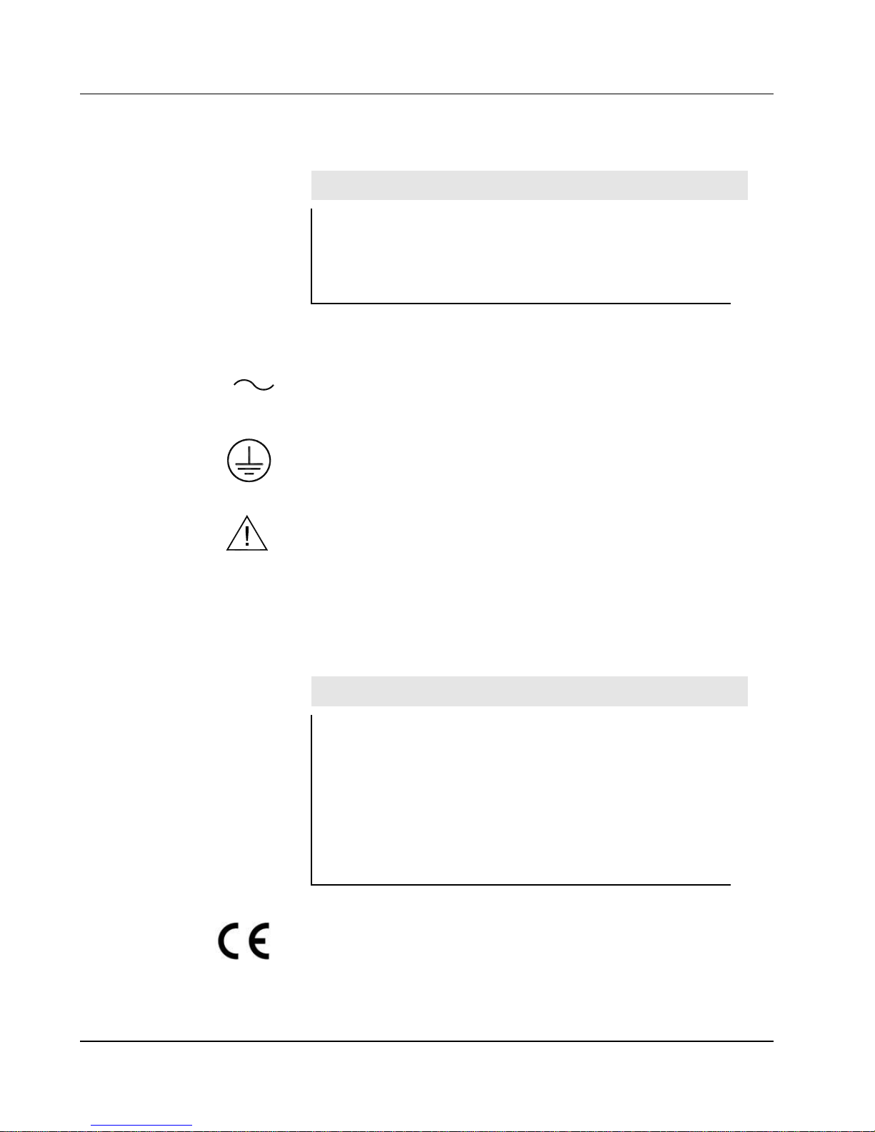
ALTERNATING CURRENT (AC) (IEC 417, No. 5032) - designates an
input receptacle that accommodates a power cord intended for connection
to AC voltages. This appears on AC panel, bottom side.
PROTECTIVE CONDUCTOR TERMINAL (per IEC 417, No. 5019)
– designates the central grounding point for the safety ground. This symbol
is visible inside the chassis.
CAUTION (per ISO 3864, No. B.3.1) – designates hazardous live voltage
and risk of electric shock. During normal use, the stabilizer legs must be
installed to avoid a tip-over of the unit. Without the stabilizer legs, a
substantial impact to the front or back of the unit could cause the unit to tip
and fall. This symbol appears on the side panels near the stabilizer leg
attachment points. Note the following precautions:
Warning!
The operator is strongly cautioned to take the following
precautions to avoid contact with internal hazardous live parts
that are accessible using a tool:
1. Turn the instrument power OFF and disconnect the power
cord.
2. Allow the instrument to sit for one minute before accessing
internal components.
The “CE” mark is used to identify this instrument as being acceptable for
use within the European Union.
Ludlum Measurements, Inc. Page 5-3 July 2018
Page 29

Model 52-1 Family Technical Manual Section 6
Section
6
Maintenance and Recalibration
Maintenance
Instrument maintenance consists of keeping the instrument clean and
periodically checking the calibration. The Model 52-1, 52-5, and 52-6 Series
of instruments may be cleaned externally with a damp cloth, using only
water as the wetting agent. Do not immerse the instrument in any liquid.
Observe the following precautions when cleaning:
1. Turn instrument OFF and disconnect the instrument power
cord.
2. Allow the instrument to sit for one minute before cleaning.
Recalibration
Recalibration is required after any repairs or adjustments have been made to
the instrument. Recalibration is not normally required following instrument
cleaning, battery replacement, or detector cable replacement.
Note:
Ludlum Measurements, Inc. recommends recalibration at
intervals no greater than one year. Check the appropriate
regulations to determine required recalibration intervals.
Ludlum Measurements offers a full-service repair and calibration
department. We not only repair and calibrate our own instruments, but most
other manufacturers’ instruments.
Calibration procedures are available upon request for customers who choose
to calibrate their own instruments.
Ludlum Measurements, Inc. Page 6-1 July 2018
Page 30

Model 52-1 Family Technical Manual Section 7
Section
7
Checkout Procedure
General
These models are set for -4 mV sensitivity (pulse height) for their plastic
scintillation detectors.
Equipment Required
1. Ludlum Model 500 Pulser or equal.
2. High-impedance voltmeter for high-voltage measurements (1000
megohm)
3. 8 to 15 Vdc power supply
4. Digital counter or oscilloscope for negative-going 5 Vdc pulses
Checkout Procedure
Checkout of the portal monitor is accomplished by determination of the
pulse threshold and high voltage of each detector interface board located on
each detector of the portal frame. No adjustments are possible to the
threshold voltage level, which is fixed by component values. The design
threshold level is -4 mV and operating high voltage is approximately 7001200 Vdc.
Proper high-voltage setting is determined by completing a high-voltage
plateau with the isotope(s) of interest. The best point of operation may
be selected by calculating a figure of merit (FOM) for each high voltage
point. The FOM can be defined as either the net source counts divided
by the square root of the background, or as the net source counts
squared divided by the background.
Ludlum Measurements, Inc. Page 7-1 July 2018
Page 31

Model 52-1 Family Technical Manual Section 7
Connect the cable from the Model 500 Pulser to one of the
detector interface boards. Apply power to the board by
supplying +12 Vdc and ground on the two-pin connector on the
detector interface board.
Attach the counter or oscilloscope to pin 1 of the TLC372
comparator. Adjust pulser amplitude to approximately -4 mV ±1
mV, until pulses just appear.
Adjust R18 until the Model 500 Pulser reads within 5% of the
correct high voltage. The correct high voltage should be
determined by running a voltage plateau with the detector and
one or more radioactive isotopes.
Ludlum Measurements, Inc. Page 7-2 July 2018
Page 32

Model 52-1 Family Technical Manual Section 8
Section
8
L
Recycling
udlum Measurements, Inc. supports the recycling of the electronics
products it produces for the purpose of protecting the environment
and to comply with all regional, national and international agencies
that promote economically and environmentally sustainable
recycling systems. To this end, Ludlum Measurements, Inc. strives to supply
the consumer of its goods with information regarding reuse and recycling of
the many different types of materials used in its products. With many
different agencies, public and private, involved in this pursuit it becomes
evident that a myriad of methods can be used in the process of recycling.
Therefore, Ludlum Measurements, Inc. does not suggest one particular
method over another, but simply desires to inform its consumers of the
range of recyclable materials present in its products, so that the user will
have flexibility in following all local and federal laws.
The following types of recyclable materials are present in Ludlum
Measurements, Inc. electronics products, and should be recycled separately.
The list is not all-inclusive, nor does it suggest that all materials are present in
each piece of equipment:
Batteries Glass Aluminum and Stainless Steel
Circuit Boards Plastics Liquid Crystal Display (LCD)
Ludlum Measurements, Inc. products which have been placed on the
market after August 13, 2005 have been labeled with a symbol recognized
internationally as the “crossed-out wheelie bin” which notifies the consumer
that the product is not to be mixed with unsorted municipal waste when
discarding; each material must be separated. The symbol will be placed near
the AC receptacle, except for portable equipment where it will be placed on
the battery lid.
The symbol appears as such:
Ludlum Measurements, Inc. Page 8-1 July 2018
Page 33

Model 52-1 Family Technical Manual Section 9
Section
9
Models 52-1, 52-1-1,
52-5, 52-5-1, 52-6,
and 52-6-1 Portable
Scintillation Portal
Monitors
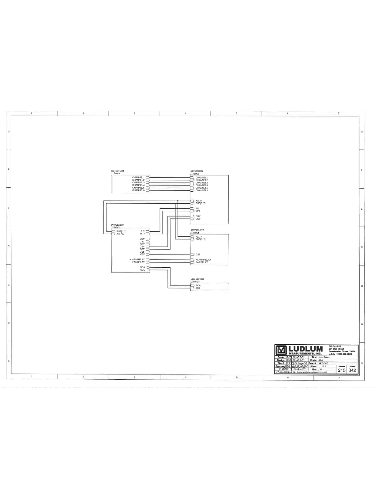
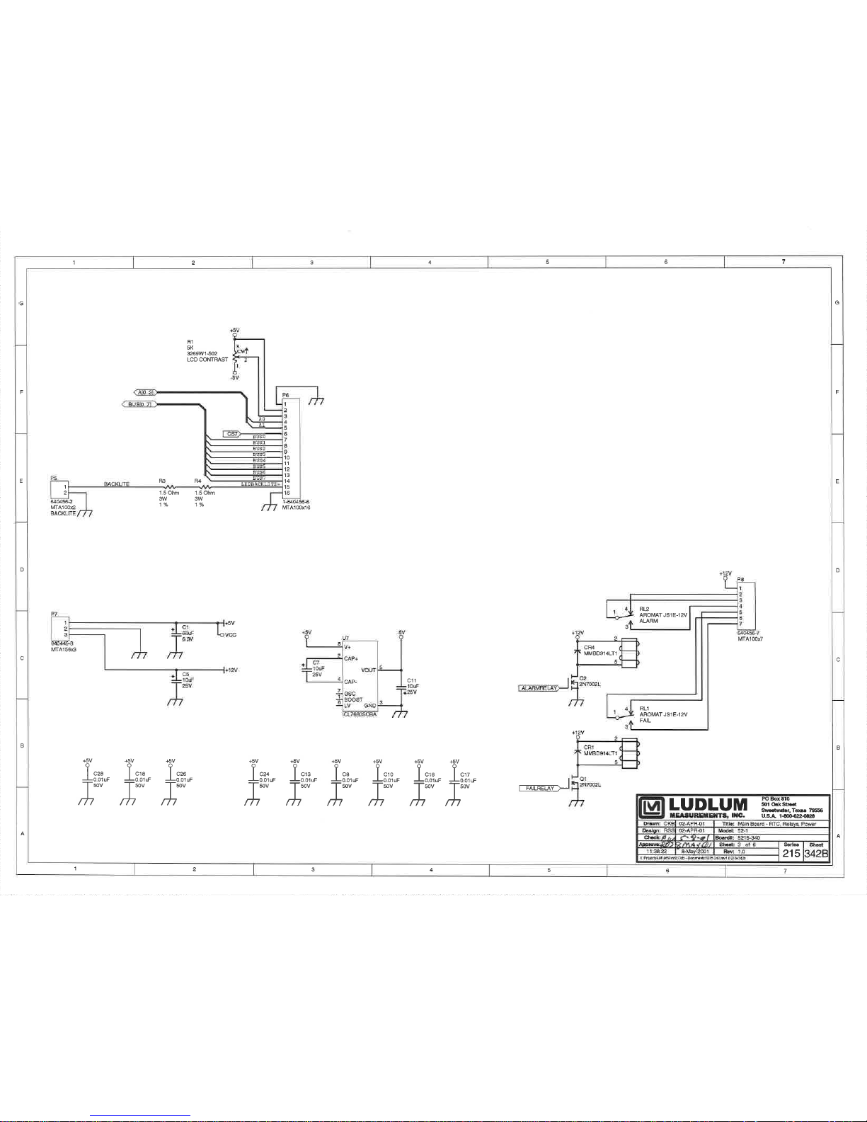
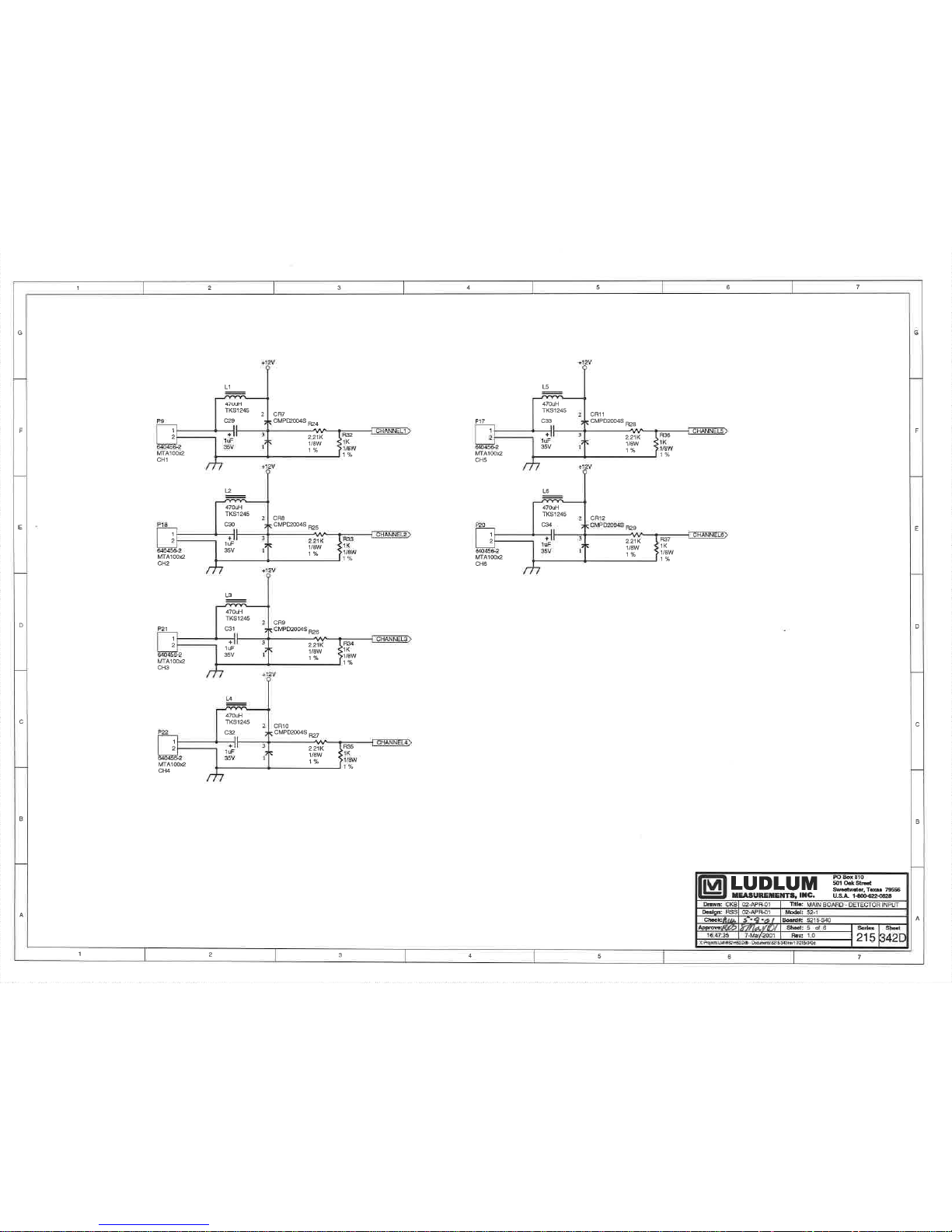
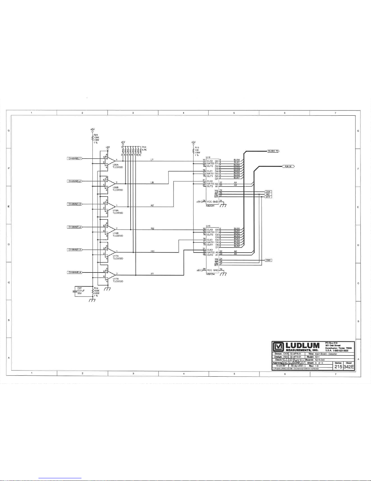
Main Board,
Drawing 215 x
342-342E
CAPACITORS
Parts List
Reference Description Part Number
UNIT Completely Assembled
Model 52-1 Portal Monitor 48-3172
UNIT Completely Assembled
Model 52-1-1 Portal Monitor 48-3258
UNIT Completely Assembled
Model 52-5 Portal Monitor 48-3393
UNIT Completely Assembled
Model 52-5-1 Portal Monitor 48-3571
UNIT Completely Assembled
Model 52-6 Portal Monitor 48-3611
UNIT Completely Assembled
Model 52-6-1 Portal Monitor 48-3603
BOARD Completely Assembled
Main Circuit Board 5215-340
C1 68µF, 6.3V 04-5654
C2-C4 0.1µF, 50V 04-5663
C5 10µF, 25V 04-5655
C6 0.1µF, 50V 04-5663
C7 10µF, 25V 04-5655
C8 0.01µF, 50V 04-5664
C9 27pF, 100V 04-5658
C10 0.01µF, 50V 04-5664
C11 10µF, 25V 04-5655
C12 27pF, 100V 04-5658
C13-C14 0.01µF, 50V 04-5664
C15 10µF, 25V 04-5655
C16-C18 0.01µF, 50V 04-5664
Ludlum Measurements, Inc. Page 9-1 July 2018
Page 34

Model 52-1 Family Technical Manual Section 9
TRANSISTORS
INTEGRATED
CIRCUITS
DIODES
Reference Description Part Number
C21 0.1µF, 50V 04-5663
C22 0.01µF, 50V 04-5664
C24 0.01µF, 50V 04-5664
C25 10pF, 100V 04-5673
C26-C28 0.01µF, 50V 04-5664
C29-C34 1µF, 35V 04-5656
Q1-Q5 2N7002L 05-5840
Q6 MMBT4403LT1 05-5842
Q7 2N7002L 05-5840
Q9 2N7002L 05-5840
Q11-Q21 2N7002L 05-5840
U1 CD74HC138M 06-6339
U2 PCF8593TD 06-6403
U3 CD74HC00M 06-6308
U4 MAX232D 06-6382
U5 27C512-15N DIP28 06-6264
U6 HM62256ALP-10SL 06-6301
U7 ICL7660SCBA 06-6437
U8 24C65ISM 06-6401
U9 N80C51FA 06-6332
U10 CD74HC573M 06-6298
U11 PCF8574TD 06-6402
U15-U16 N82C54 06-6309
U17 TLC372ID 06-6290
U18 PCF8574TD 06-6402
U19-U20 TLC372ID 06-6290
CR1 MMBD914LT1 07-6353
CR2-CR3 CMPD2004S 07-6402
CR4-CR6 MMBD914LT1 07-6353
CR7-CR12 CMPD2004S 07-6402
Ludlum Measurements, Inc. Page 9-2 July 2018
Page 35

Model 52-1 Family Technical Manual Section 9
RESISTORS
RESISTOR NETWORK
CRYSTALS
INDUCTORS
CONNECTORS
MISCELLANEOUS
Reference Description Part Number
R1 5k TRIMMER 09-6918
R2 4.75k 12-7858
R3-R4 1.5 OHM 12-7602
R7 8.25k 12-7838
R8 4.75k 12-7858
R9 10k 12-7839
R10 1k 12-7832
R12-R13 10k 12-7839
R14 100k 12-7834
R23 100k 12-7834
R24-R29 2.21k 12-7835
R32-R37 1k 12-7832
RN1 NETWORK-220k 12-7923
RN2 NETWORK-22k 12-7917
RN3 NETWORK-220k 12-7923
RN4 NETWORK-4.7k 12-7918
Y1 6.144MHZ 01-5262
Y2 32.768Khz 01-5305
L1-L6 470 µH 21-9699
P1-P2 640456-5 MTA 100 13-8057
P3-P4 640456-3 MTA 100 13-8081
P5 640456-2 MTA 100 13-8073
P6 1-640456-6 13-8134
P7 640445-3 MTA 156 13-8125
P8 640456-7 MTA 100 13-8115
P9 640456-2 MTA 100 13-8073
P10 1-640456-0 MTA 100 13-8066
P17-P18 640456-2 MTA 100 13-8073
P19 1-640456-1 MTA 100 13-8059
P20-P22 640456-2 MTA 100 13-8073
B1 BATT-3V LITHIUM 22-9986
Ludlum Measurements, Inc. Page 9-3 July 2018
Page 36

Model 52-1 Family Technical Manual Section 9
Detector Interface
Board, Drawing
215 x 347
CAPACITORS
DIODES
TRANSISTORS
RESISTORS
Reference Description Part Number
BOARD Completely Assembled
Detector Interface Board 5215-347
C1 10µF, 25V 04-5655
C2 4.7µF, 25V 04-5653
C3 0.001µF, 100V 04-5659
C4 10µF, 25V 04-5655
C5 47µF, 10V 04-5666
C6 0.001µF, 10V 04-5659
C7 0.01µF, 50V 04-5664
C8 1µF, 35V 04-5656
C9-C10 0.01µF, 50V 04-5664
C11 0.001µF, 2kV 04-5703
C12 10 pF, 100V 04-5673
C13 0.01µF, 50V 04-5664
C14 0.01µF, 2KV 04-5722
C15 47 pF, 100V 04-5660
C16 10µF, 25V 04-5655
C17 0.01µF, 2kV 04-5722
C18-C22 0.001µF, 2kV 04-5703
C23-C27 0.01µF, 500V 04-5696
CR1 CMSH1-40M 07-6411
CR2-CR8 CNOD2004S 07-6402
Q1 MTD2N50E 05-5855
R1-R4 150 OHM 12-7965
R5-R6 47.5 OHM 12-7966
R7 100k 12-7834
R8 1.82k 12-7030
R9 10k 12-7839
R10 4.75k 12-7858
R11 100 OHM 12-7840
R12 1k 12-7832
R13-R15 10k 12-7839
R16 4.75k 12-7858
Ludlum Measurements, Inc. Page 9-4 July 2018
Page 37

Model 52-1 Family Technical Manual Section 9
INTEGRATED CIRCUITS
VOLTAGE REGULATOR
INDUCTORS
CONNECTORS
LEDs
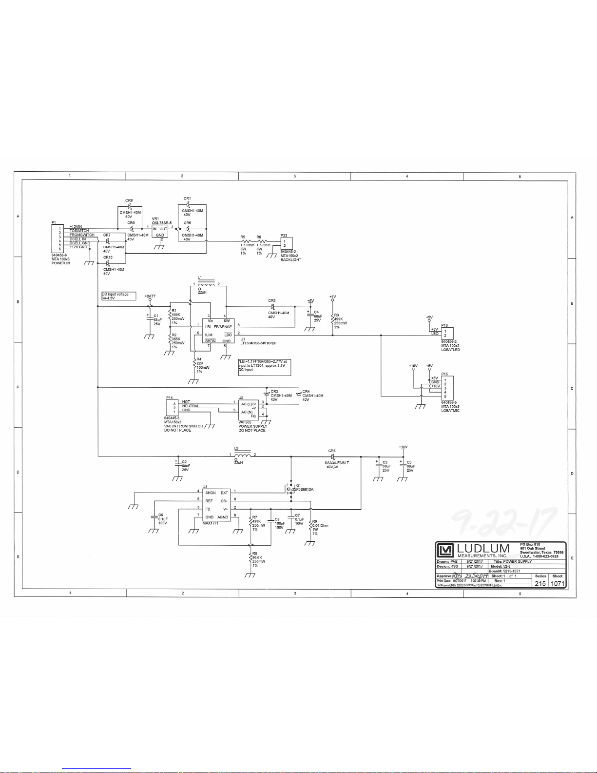
Power Supply,
Drawing 215 x 1072
CAPACITORS
INTEGRATED
CIRCUITS
DIODES
Reference Description Part Number
R17 392k 12-7841
R18 1 M TRMR 09-6911
R19-R20 1 M 12-7844
R21 1 G 12-7686
R23 1 M 12-7844
U1 ICL7667CBA 06-6510
U2 MAX985EUK-T 06-6459
U3 CA3096M 06-6288
U4 MAX641ACSA-5 06-6388
VR1 LT1460KCS3-2.5TR 05-5867
VR2 LM78L05ACM 05-5864
L1-L2 470 µH 21-9224
P20 640456-2 MTA-100 13-8073
P34 640456-2 MTA-100 13-8073
W1 COAXIAL CONNECTOR 21-9463
DS1 LED-SML-LX1206SRC-TR RED 1206
07-6648
BOARD Completely Assembled
Power Supply 5215-1071
C1-C5 68µF, 25V 04-5828
C6-C7 0.1µF, 100V 04-5792
C8 100pF, 100V 04-5661
U1 LT1304CS8 06-6434
U3 MAX1771 06-6845
CR1-CR5 CMSH1-40M 07-6411
CR6 SSA34-E3/61T 07-6610
CR7-CR10 CMSH1-40M 07-6411
Ludlum Measurements, Inc. Page 9-5 July 2018
Page 38

Model 52-1 Family Technical Manual Section 9
TRANSISTORS
RESISTORS
INDUCTORS
CONVERTER
CONNECTORS
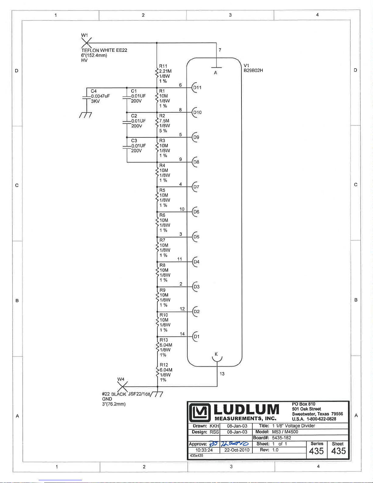
1 1/8 inch Voltage
Divider,
Drawing 435 x 435
CAPACITORS
RESISTORS
Reference Description Part Number
Q1 FDS6612A 05-5742
R1 499k, 250mW 12-7037
R2 365k, 250mW 12-7049
R3 499k, 250mW 12-7037
R4 22k, 100mW 12-7179
R5-R6 1.5Ohm, 3W 12-7602
R7 499k, 250mW 12-7037
R8 86.6k, 250mW 12-8275
R9 0.04Ohm, 1W 12-8276
L1-l2 22µH 21-9208
VR1 OKI-78SR-5 21-8637
P1 640456-6 MTA100X6 13-8095
P15 640456-5 MTA100X5 13-8057
P16 640456-2 MTA100X2 13-8073
P33 640445-2 MTA156X2 13-8098
BOARD Completely Assembled
Voltage Divider 5435-182
C1-C3 0.01µF, 200V 04-5725
C4 0.0047µF, 3KV 04-5547
R1 10M, 1/8W, 1% 12-7996
R2 7.5M, 1/8W, 5% 12-7971
R3-R10 10M, 1/8W, 1% 12-7996
R11 2.21M, 1/8W, 1% 12-7002
R12-R13 6.04M, 1/8W, 1% 12-7071
Ludlum Measurements, Inc. Page 9-6 July 2018
Page 39

Model 52-1 Family Technical Manual Section 9
Resistor Board,
Drawing 215 x 782
CAPACITORS
RESISTORS
CONNECTORS
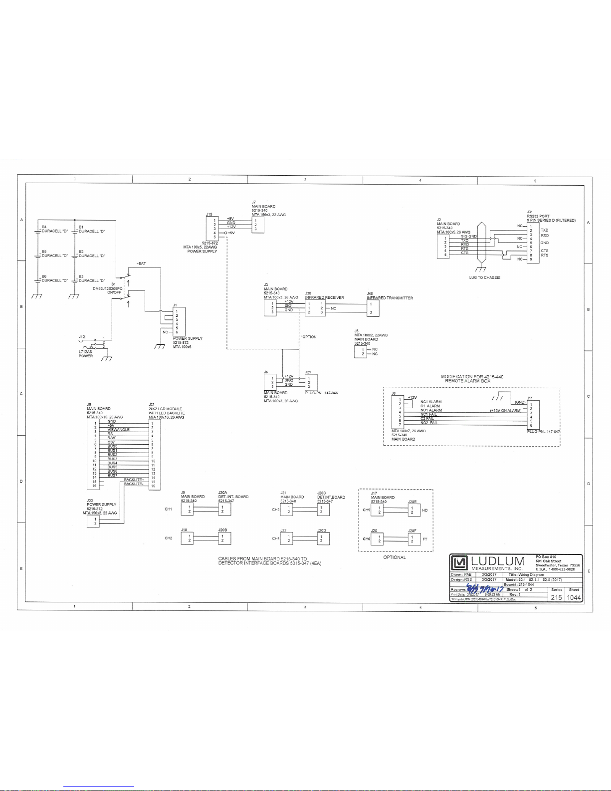
Wiring Diagram,
Drawing 215 x 1044
CONNECTORS
MISCELLANEOUS
Miscellaneous
Parts
Reference Description Part Number
BOARD Completely Assembled
Model 52-1 Resistor Board 5215-781
C1-C3 0.1 µF, 25V 04-5744
R1 332 OHM 12-7854
R3-R4 150 OHM 12-7062
R5-R12 332 OHM 12-7854
Reference Description Part Number
P100 640456-2 MTA-100 13-8073
P101 640456-7 MTA-100 13-8115
P102 640456-4 MTA-100 13-8088
P103 640456-6 MTA-100 13-8095
P104-P105 640456-2 MTA-100 13-8073
P106 640456-5 MTA-100 13-8057
P107 640456-4 MTA-100 13-8088
P108 640456-7 MTA-100 13-8115
S1 DM62J12S205PQ 08-6715
J12 L712AS 21-8795
J29 RM12BRD-3PH(71)3PM 13-8546
J31 RS-232 9-PIN “D” 13-8556
J38 IR RECEIVER 2310737
J40 IR TRANSMITTER 2310738
B1-B6 BATTERY – “D” 21-9313
FP5 MEMBRANE SWITCH KEYPAD 7215-779
SP1 ALARM-TXC-V86-515-Q 5-15VDC XLOUD
21-8802
Model 52-1 12 Vdc Car Power Cable 8515-819
Model 52-1 +12V Wall Transformer Cable 8303-1029
Ludlum Measurements, Inc. Page 9-7 July 2018
Page 40

Model 52-1 Family Technical Manual Section 10
Section
10
Drawings
Front of Manual
Front Panel, Drawing 215 x 999
AC Panel Assembly, Drawing 215 x 999A
Back of Manual
Boards and Wiring Diagram
Main Board, Drawing (6 sheets), 215 x 342-342E
Main Board Layout, Drawing 215 x 343
Detector Interface Board, Drawing 215 x 347
Detector Interface Board Layout, Drawing 215 x 348A
Power Supply Board, Drawing 215 x 1071
Power Supply Board Layout, Drawing 215 x 1072
1 1/8 inch Voltage Divider, Drawing 435 x 435
1 1/8 inch Voltage Divider Component Layout, Drawing (2 sheets)
435 x 436A
Resistor Board, Drawing 215 x 782
Resistor Board Layout, Drawing 215 x 781A (2 sheets)
Wiring Diagram-Electronics, Drawing 215 x 1044 (2 sheets)
Assembly and Setup
Model 52-1 & 52-5 Series Packing Instructions, Drawing 215 x 225C
Ludlum Measurements, Inc. Page 10-1 July 2018
Model 52-6 Series Packing Instructions, Drawing 215 x 633B
Model 52-1 & 52-5 Series Overall Assembly, Drawing 215 x 225A
Model 52-6 Overall Assembly Drawing 215 x 633A
Page 41

Model 52-1 Family Technical Manual Section 10
Model 52-1 & 52-5 Series Dimensions, Drawing 215 x 225
Model 52-6 Series Dimensions, Drawing 215 x 633
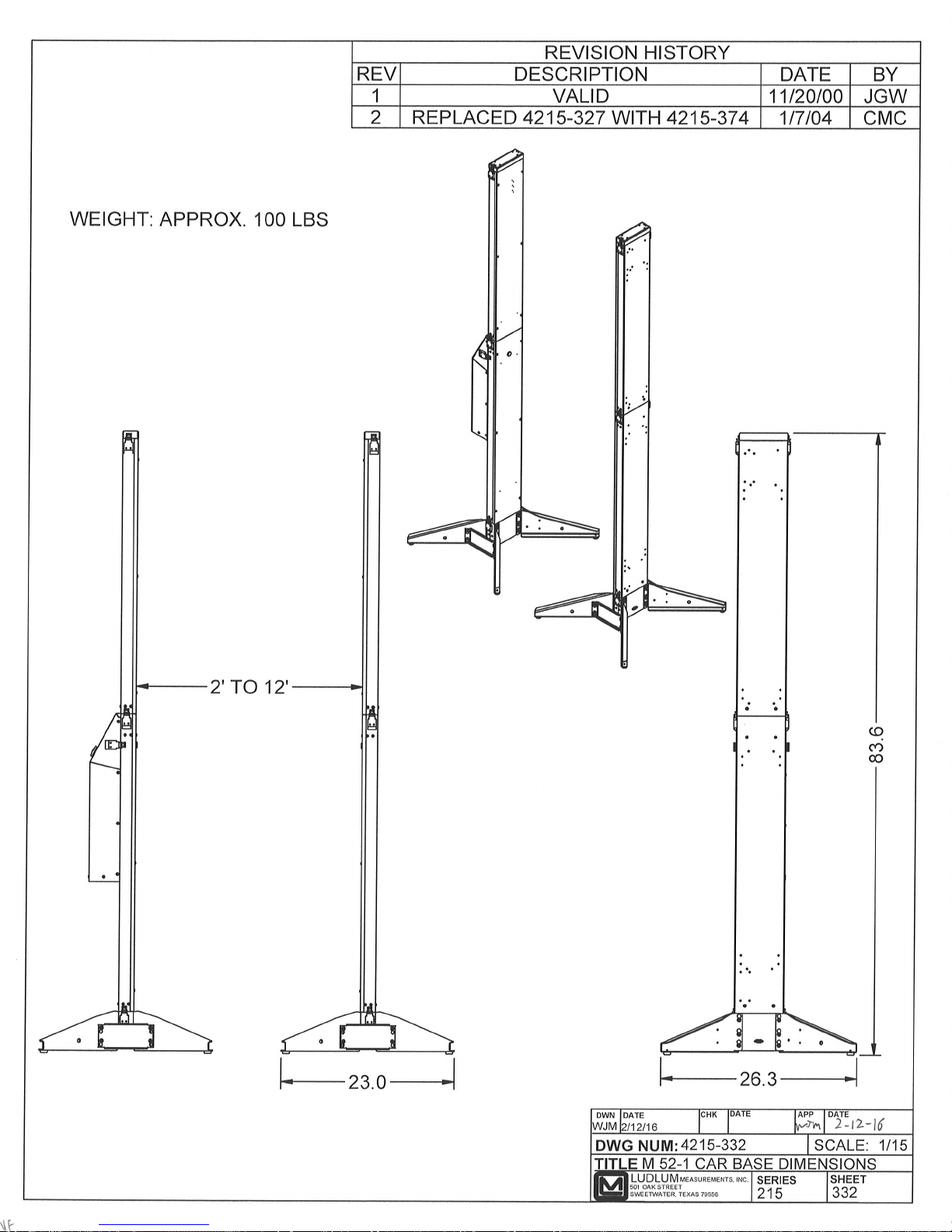
Car Base Assembly, Drawings 215 x 332 & 332A
Car Base Setup, Drawing 215 x 374 & 374B
Ludlum Measurements, Inc. Page 10-2 July 2018
Page 42
Page 43

Page 44

Page 45

Page 46
Page 47

Page 48

Page 49

Page 50
Page 51

Page 52
Page 53

Page 54

Page 55

Page 56

Page 57

Page 58

Page 59

Page 60
Page 61

Page 62

Page 63

Page 64
Page 65

Page 66

Page 67

Page 68

Page 69

Page 70

Page 71

Page 72

Page 73

Page 74

Page 75

Page 76
Page 77

Page 78

Page 79

Page 80

Page 81

Page 82

Page 83

Page 84

Page 85

Page 86

Page 87

Page 88

Page 89

Page 90

Page 91

Page 92
Page 93

Page 94

Page 95

Page 96

Page 97

Page 98

Page 99

 Loading...