


LUDLUM MODELS 375 (INCLUDING SERIES ONE),
375/1, 375/2 AND 375/4
DIGITAL WALL-MOUNT AREA MONITORS
May 2017
Serial Number 278020 and Succeeding
Serial Numbers

LUDLUM MODELS 375 (INCLUDING SERIES ONE),
375/1, 375/2 AND 375/4
DIGITAL WALL-MOUNT AREA MONITORS
May 2017
Serial Number 278020 and Succeeding
Serial Numbers

Ludlum Measurements, Inc. May 2017

STATEMENT OF WARRANTY
Ludlum Measurements, Inc. warrants the products covered in this manual to be free of
defects due to workmanship, material, and design for a period of twelve months from
the date of delivery. The calibration of a product is warranted to be within its
specified accuracy limits at the time of shipment. In the event of instrument failure,
notify Ludlum Measurements to determine if repair, recalibration, or replacement is
required.
This warranty excludes the replacement of photomultiplier tubes, G-M and
proportional tubes, and scintillation crystals which are broken due to excessive
physical abuse or used for purposes other than intended.
There are no warranties, express or implied, including without limitation any implied
warranty of merchantability or fitness, which extend beyond the description of the
face there of. If the product does not perform as warranted herein, purchaser’s sole
remedy shall be repair or replacement, at the option of Ludlum Measurements. In no
event will Ludlum Measuremen ts be liable for damages, lost revenue, lost wages, or
any other incidental or consequential damages, arising from the purchase, use, or
inability to
use product.
RETURN OF GOODS TO MANUFACTURER
If equipment needs to be returned to Ludlum Measurements, Inc. for repair or calibration, please send to the address below. All shipments should include
documentation containing return shipping address, customer name, telephone number, description of service requested, and all other necessary
information. Your cooperation will expedite the return of your equipment.
ATTN: REPAIR DEPARTMENT
501 OAK STREET
SWEETWATER, TX 79556
Ludlum Measurements, Inc. May 2017
LUDLUM MEASUREMENTS, INC.
800-622-0828 325-235-5494
FAX 325-235-4672


Table of Contents
Introduction 1
Getting Started 2
External Detector (Option) 2-1
Power Up 2-1
Radiation Units 2-2
Checking Parameters 2-2
*Model 375 Series One 2-3
Setting Alarm Points 2-3
Operational Check 2-4
Return for Repair and Calibration 2-5
Specifications 3
Operator Controls and Setup 4
Calibration Controls 4-1
Dipswitch (under calibration cover) 4-2
RS-232 Output 4-3
9-Pin Remote Data Connector 4-3
9-Pin Relays Connector 4-4
Typical Internal Detector Setups 4-4
Common Options and Modifications 5
Relay Options 5-1
Ethernet Interface Option 5-5
Time and Date Stamp Option 5-5
Printer DIP Switch Settings 5-6
Sigma Alarm Modification Option 5-7
4 to 20 mA Isolated Output Driver Option 5-8
Safety Considerations 6
Environmental Conditions for Normal Use 6-1
Cleaning Instructions and Precautions 6-1
Warning Markings and Symbols 6-2
Electrical Safety Precautions 6-3
Replacement of Main Fuse 6-4
Ludlum Measurements, Inc. May 2017

Models 375 (Including Series One), 375/1, 375/2 & 375/4
Detector Connector 6-4
Battery Replacement 6-4
Calibration 7
High Voltage 7-1
Calibration Parameters 7-1
Analog Output 7-2
Discriminator 7-2
Battery Charge 7-2
Recycling 8
Parts List 9
Model 375 Digital Wall-Mount Area Monitor without Detector 9-1
Model 375/1 Digital Wall-Mount Area Monitor 9-1
Model 375/2 Digital Wall-Mount Area Monitor 9-1
Model 375/4 Digital Wall-Mount Area Monitor 9-1
Model 375 Series One without Detector 9-1
Model 375/2 Series One 9-1
Model 375/4 Series One 9-1
Main Board, Drawing 558 x 1 9-1
Wiring Diagram, Drawing 558 x 136 9-6
Internal Detectors 9-6
Drawings and Diagrams 10
Ludlum Measurements, Inc. May 2017

Models 375 (Including Series One), 375/1, 375/2 & 375/4 Section 1
Section
1
Introduction
he Model 375 Digital Wall-Mount Area Monitor is designed for
visibility and ease of use. Featuring a wall-mount chassis, the Model
T
radiation alarm (red), instrument failure (red), and low battery (yellow). A green
status light is a positive indication of instrument operation.
Parameters are protected under a calibration cover. Calibration is easily
accomplished by moving the cal dipswitch to the right, and using the
pushbuttons to increment or decrement the calibration constant, dead time
correction, and alarm point parameters. Parameters are stored in non-volatile
memory (retained even with power disconnected).
A five-decade logarithmic analog output is provided. A battery backup provides
48 hours of additional use after the primary power is removed. Depending on
the needs of the customer, the Model 375 comes equipped with an internal
detector or a connector for use with an external detector. The Model 375/1
comes equipped with an internal CsI scintillator detector. The Model 375/2
and 375/4 come equipped with internal, energy-compensated GM detectors.
375 has a four-digit LED display that is readable from 9.1 m (30 ft)
away. Backlit indicators warn of low-radiation alarm (yellow), high-
The Ludlum Model 375 Series One is a Model 375 with modified firmware.
Changes include certain display values in decimal points and units. Details can
be found in sections “Getting Started” and “Specifications.”
Ludlum Measurements, Inc. Page 1-1 May 2017

Models 375 (Including Series One), 375/1, 375/2 & 375/4 Section 2
Section
2
Getting Started
he Model 375 Digital Wall-Mount Area Monitor is designed for
ease of use. This section of the manual is designed to help the first-
T
manual provide more detailed information.
External Detector (Option)
The Model 375 comes equipped with either an internal detector or a
connector for use with an external detector. If your Model 375 is equipped
with a connector on the bottom side of the chassis, an external detector is
required. If you have an external detector, use the cable provided to connect
it to the Model 375.
time user get started. Initial power-up and basic features of the
Model 375 will be discussed in this section. Other sections of the
Warning!
Potential electrical shock hazard - Do not touch the center
pin of the detector connector unless the unit has turned off
and power has been removed for at least one minute.
Power Up
Plug the wall-mount 9 Vdc power supply into a suitable wall (Mains) outlet.
Ludlum Measurements, Inc. Page 2-1 May 2017
Note:
Splicing or re-terminating cables must be done carefully.
Improper termination will result in the “shorting out” of the
detector voltage, a DET FAIL, and/or blown-fuse condition.
Models 375 (Including Series One), 375/1, 375/2 & 375/4 Section 2
If the RS-232 feature is used, plug in a suitably wired 9-pin
connector cable. (See Page 4-4 for the pin assignment of the 9-pin
connector.) Turn power ON with the left side panel switch. Do
not turn power OFF unless the unit is to be removed from service.
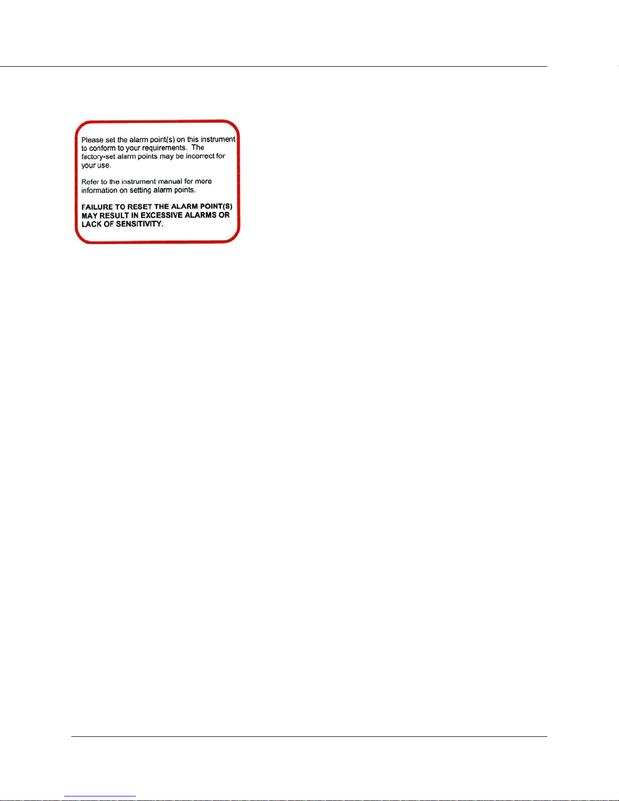
Read and then remove the sticker (illustrated to the left) from the
instrument calibration cover. Checking and setting of the alarm
point(s) is discussed in detail below and on pages 2-3 and 7-1 of
this manual.
Initial power-up will momentarily activate the internal front-panel lights,
sound the audio, and display "8888" on the 4-digit LED display. The
firmware version number (396Nyy) is then displayed as "396" and "xxyy"
(where xx and yy represents the current version number).
When the instrument has finished measuring background, it will display the
current radiation reading and begin checking for an alarm condition.
Radiation Units
The Model 375 may be calibrated for almost any desired radiation units of
measure. Common units of measure include mR/hr, µR/hr, R/hr, mSv/h,
µSv/h, cps, cpm, and kcpm. In each case, the unit of measure is indicated
underneath the four-digit display. Throughout the rest of this manual, the
notation <units> will be used as a substitute.
Checking Parameters
Check the low alarm point setting by pressing the LOW ALARM button. The
low alarm point will be displayed as long as the button is pressed. The low
alarm point is in units of <units>. The low alarm point can be set from 0.1
<units> to 9999 <units>*.
Check the high alarm point setting by pressing the HIGH ALARM button. The
high alarm point will be displayed as long as the button is pressed. The
highalarm point is in units of <units>. The high alarm point can be set from
0.1 <units> to 9999 <units>*.
Check the calibration constant by pressing the
calibration constant will be displayed as long as the button is pressed. The
calibration constant is in units of cpm (counts per minute) per <units>*.
The calibration constant can be set from 0.1 cpm/<units> to 9999
cpm/<units>*.
CAL CONST button. The
Ludlum Measurements, Inc. Page 2-2 May 2017

Models 375 (Including Series One), 375/1, 375/2 & 375/4 Section 2
Check the detector dead time correction by pressing down on the DEAD
TIME
button. The dead time correction will be displayed as long as the
button is pressed. The dead time correction is in units of microseconds*.
The dead time correction can be set from 0.1 microseconds to 9999 microseconds*.
* Model 375 Series One: In the special case of the Model 375 Series One,
make note of the following changes resulting from firmware modification:
With the RANGE dipswitch in the left position, two decimal places will
be displayed.
With the
RANGE dipswitch in the right position, no decimal place will be
displayed.
Calibration constant will be displayed in cps per unit, instead of cpm per
unit.
Dead Time Correction will display in 10
ths
of microseconds (i.e. 0.50
µsec instead of 5 µsec).
Setting Alarm Points
The LOW ALARM and HIGH ALARM points can only be changed while the
instrument is in calibration mode. Switch the top dipswitch CAL MODE
(behind the calibration cover) to the right to place the instrument into
calibration mode.
Changing alarm points is done by holding down the corresponding
parameter key and pressing the up or down arrow buttons. Alarm points can
be set in the range of 0.1 to 9999*. When an alarm point is changed, the
instrument will sound an audible beep to confirm the saving of the
parameter, and will then return to displaying the current radiation level.
Ludlum Measurements, Inc. Page 2-3 May 2017
Note:
Once the alarm point(s) is set, it is important to remember to
switch the CAL MODE switch back to the left. This action
protects the parameters from inadvertent changes.

Models 375 (Including Series One), 375/1, 375/2 & 375/4 Section 2
Operational Check (optional)
The operational check is an important assurance that the radiation detector
and electronics are working correctly.
Note:
Ludlum Measurements suggests that an operational check be
performed on a regular basis. Local procedures may
supersede this suggestion.
For an operational check, it is necessary to use a radiation check source (not
included, but available). When not being used, store the check source in a
secure area.
Note:
LMI check sources present very minimal risks and are
therefore unlicensed (Exempt Quantity Sources reference:
10 CFR 30.71 Schedule B). The radioactive element is sealed
(permanently bonded or fixed inside a capsule) so you need
not wash your hands after handling. Radiation exposure
while handling this source is very minimal with no identified
long or short term risks. Although the amount of radiation
given off by exempt sources is so low that it presents no
significant hazard, they should be handled with care and
respect. Time, distance, and shielding are the best ways to
control exposure.
1. Taking the source in hand, place it so that it is located on or near
the center (same location each time) of the detector. (For
internal detector models, a metal plate on the bottom of the
chassis identifies the location of the internal detector.) Hold it
there for approximately five seconds or until the reading
stabilizes. Take note of the displayed level of radiation.
2. Verify that the reading is within 20% of the last reading
obtained. Remove the source from the detector.
Ludlum Measurements, Inc. Page 2-4 May 2017
3. If an alarm is activated, ensure that all visual and audible devices
(if applicable) work correctly.

Models 375 (Including Series One), 375/2, 375/4 & 375WT Technical Manual
Return for Repair and Calibration
To return an instrument for repair or calibration, provide sufficient packing
material to prevent damage during shipment.
Every returned instrument must be accompanied by an Instrument Return
Form, which can be downloaded from the Ludlum website at
www.ludlums.com. Find the form by clicking the “Support” tab and
selecting “Repair and Calibration” from the drop-down menu. Then choose
the appropriate Repair and Calibration division where you will find a link to
the form.
Ludlum Measurements, Inc. Page 2-5 May 2017

Models 375 (Including Series One), 375/1, 375/2 & 375/4 Section 3
Section
3
Specifications
Compatible Detectors: GM, proportional, and scintillation
Display: four-digit LED display with 2 cm (0.8 in.) character height
Display Range: 000.0-9999 (Series One: 00.00-9999)
Display Units: can be made to display in µR/hr, mR/hr, R/hr, µSv/h,
mSv/h, Sv/h, µrem/hr, mrem/hr, rem/hr, cpm, cps, and others
Linearity: readings within 10% of true value with detector connected
Operating Range: depends upon the type of detector used. The
operating range of the 375/2 is from 1 µSv/h to 10 mSv/h (0.1 mR/hr
to 1 R/hr). The operating range of the 375/4 is from 0.01 mSv/h to 100
mSv/h (1 mR/hr to 10 R/hr). External detectors will have different
operating ranges.
Response: typically 3 seconds from 10% to 90% of final reading
Status (green light): indicates the instrument is functioning properly
Low Alarm: indicated by a yellow light and slow beep (1 per second)
audible tone (can be set at any point from 0.0-9999 {00.00-9999 for
Series One})
High Alarm: indicated by a red light and a fast beep (4 per second)
audible tone (can be set at any point from 0.0-9999 {00.00-9999 for
Series One})
Ludlum Measurements, Inc. Page 3-1 May 2017
Note:
Audible indicators can be configured as a single beep by
dipswitch if desired. Audio intensity is controlled by rotating
the baffle on the audio device. Audio intensity may also be
adjusted by moving an internal connector.

Models 375 (Including Series One), 375/1, 375/2 & 375/4 Section 3
DET Fail: indicated by a red light and an audible tone greater than 68 dB
at 6.1 ft (2 m) for conditions of detector overload, no count from
detector or instrument failure
Low Bat: indicated by a yellow light, beginning when two hours of
battery life remain
Connector: series ˝C˝ (others available)
Ethernet (optional): 10 Base-T connection for use with Ludlum software
Calibration Controls: accessible from the front of instrument (protective
cover provided)
High Voltage: adjustable from 450-2500 volts
Dead Time: adjustable to compensate for dead time of the detector and
electronics (can be read on the display)
Overload: a display reading of -OL- and audible FAIL alarm indicate
detector saturation. It is normally set to initiate just above the highest
range of the detector.
Over-range: A display reading of ˝----˝ and activated low and high alarms
indicate that the radiation field being measured has exceeded the counting
range of the instrument (or when dead time correction accounts for more
than 75% of the displayed reading).
Data Output: A 9-pin connector with female sockets provides five-
decade log output, RS-232 output, signal ground connection,
HIGH ALARM signals (current sink), and direct connection to battery and
FAIL and
ground
Relays: A 9-pin connector with male pins provides connection to three
fail-safe form C relays, activated by the LOW ALARM (alert) High
ALARM, and instrument FAIL. These contacts are potential-free (nonpowered), but can handle 125 Vac at 0.3 A or 30 Vdc at 1 A.
RS-232 Output: a 2-second dump for computer data logging
Remote (optional): Ludlum Model 271 or 272 remote units
Ludlum Measurements, Inc. Page 3-2 May 2017

Models 375 (Including Series One), 375/1, 375/2 & 375/4 Section 3
Audio: Intensity can vary from approximately 68 dB to 100 dB through
operation of the external rotary baffle and the internal voltage
connection. Frequency is approximately 3 kHz.
Power: 9 Vdc wall-mount adapter, handles any mains voltage in the
world, supplied with four sets of prongs for almost any style wall
receptacle
Battery Life: typically 48 hours in non-alarm condition; 12 hours in alarm
condition
Battery Charger: battery is continuously trickle charged when the
instrument is connected to line power and turned on
Warning!:
Only certified technician or calibration personnel should
replace battery.
Environmental Rati ng: NEMA (National Electrical Manufacturers
Association) rating of 1; IP (Ingress Protection) rating of 40. (Protective
enclosures are available for harsher environments.)
Construction: aluminum housing with ivory powder-coat finish
Size: 18.7 x 24.6 x 6.4 cm (7.4 x 9.7 x 2.5 in.) (H x W x D)
Weight: 2.1 kg (4.7 lb)
Ludlum Measurements, Inc. Page 3-3 May 2017

Models 375 (Including Series One), 375/1, 375/2 & 375/4 Section 4
Section
4
Operator Controls and Setup
Calibration Controls
Remove the calibration cover to expose the calibration controls.
Warning!
Do not touch the circuit board in the calibration window
due to potential for electric shock.
The calibration controls include the up/down buttons, five calibration
potentiometers, and the option dipswitch (detailed in the following
subsection). The five potentiometers are detailed below.
ANALOG: used to adjust the logarithmic analog voltage output. Adjusted
in calibration mode to the full-scale voltage reading or adjusted to a
known point at some given reading.
Ludlum Measurements, Inc. Page 4-1 May 2017
HV: used to set the high voltage required for detector operation.
Adjustable from 450-2500 Vdc. The high voltage required will depend
on the type of detector used. Internal GM detectors typically require 550
Vdc. Be sure to check the high voltage with a high impedance (1000Mohm impedance) voltmeter only. A high-voltage checkpoint is located
next to the
DISC: internal discriminator used to set negative pulse threshold for
counting pulses from the detector. Pad allows direct measurement of
threshold voltage. Utilize a Ludlum Model 500 Pulser or equivalent to
inject pulses of the desired threshold size. The pulse height threshold is
adjustable from 2.0 mVdc to 100 mVdc.
BAT CHARGE: used to set the backup battery trickle charging voltage. It
is set to 6.9 Vdc while the battery is disconnected.
HV potentiometer.

OVERLOAD: used to set the detector current overload point. When
excessive radiation causes the detector to overload, this set point will
cause the FAIL light to engage, and the display will be forced to -OL-.
Dipswitch (under calibration cover)
When the calibration cover is removed, a four-pole dipswitch is accessible
that can activate or deactivate options. These four options are CAL MODE,
LATCH ALARM, RANGE, and SINGLE BEEP.
Dipswitch 1: Switching the top CAL MODE switch to the right places the
instrument into calibration mode. Parameters can only be changed while
the instrument is in calibration mode. Calibration mode also changes the
analog output to full-scale so that the full-scale voltage may be set by the
ANALOG potentiometer. Calibration mode also slows the response time
of the display and increases the accuracy. If the display seems too erratic,
leaving this switch in the calibration mode during operation will help.
Moving the CAL MODE switch back to the left locks the parameters and
disables any further changes.
Dipswitch 2: The second switch, LATCH ALARM, changes the high
alarm to a latching alarm. This switch does not affect the low alarm,
which is always non-latching. When switched to the left, the high alarm
is non-latching; the alarm automatically turns off when the radiation
level drops below the alarm point. When switched to the right, the high
alarm light and audio signals are latched until either the LOW ALARM or
HIGH ALARM button is pressed.
* See note on page 2-3 regarding Model 375 Series One.
Ludlum Measurements, Inc. Page 4-2 May 2017
Dipswitch 3: The third switch, RANGE, selects the range of the
instrument. To select the 0.1 <units> - 999.9 <units>* range, switch the
RANGE switch to the left. To select the 1 <units> - 9999 <units>*
range, switch the RANGE switch to the right.
Dipswitch 4: Switching the fourth switch to the right places the
instrument into SINGLE-BEEP mode. This option limits the audio
output to a single half-second beep on LOW ALARM and HIGH ALARM.
DET FAIL audio output (steady tone) is not limited.

Models 375 (Including Series One), 375/1, 375/2 & 375/4 Section 4
RS-232 Output
With the CAL MODE dipswitch in the left position, the Model 375 dumps RS232 data onto pin 4 of the 9-pin connector every two seconds.
The RS-232 data includes the
current radiation readings and the
current condition of the status
lights. The data is presented in the
following format:
BYTE1 0 x
BYTE2 x x
BYTE3 x OR x
BYTE4 x x
BYTE5 . .
BYTE6 x 0
BYTE7 Audio Status =1=on
BYTE8 High Alarm Status =1=on
BYTE9 Low Alarm Status =1=on
BYTE10 Over Range Status=1=on
BYTE11 Monitor Status =1=on
BYTE12 Error Code
BYTE13 Carriage Return (ODH)
BYTE14 Line Feed (0AH)
9-Pin Remote Da ta Connector
(female sock ets)
The 9-pin connector provides output signals from the instrument and
input voltage to the instrument. The pin assignments are:
pin1- +BATTERY
pin2- GND IN
pin3- FAIL_L
pin4- RS232 DUMP
pin5- ANALOG OUT
pin6- CHASSIS GND
pin7- HIGH ALARM_L
pin8- EXT RESET_L
pin9- +5VDC OUT
The FAIL and HIGH ALARM digital signal outputs are open drain 2N7002
outputs, able to sink about 50 mA each.
Ludlum Measurements, Inc. Page 4-3 May 2017

Models 375 (Including Series One), 375/1, 375/2 & 375/4 Section 4
9-Pin Relays Connector (male pins)
The 9-pin relay connector provides a Form C (common, normally open, and
normally closed) contact for the three fail-safe relays of LOW ALARM
(alert), HIGH ALARM, and FAIL.
The pin assignments are (shown energized):
pin1- FailNO
pin2- FailNC
pin3- AlertCOM
pin4- AlarmNO
pin5- AlarmCOM
pin6- FailCOM
pin7- AlertNO
pin8- AlertNC
pin9- AlarmNC
Typical Internal Detector Setups
Model 375/2
Typical response and set points for the model 375 with internal energycompensated LND 71210 GM detector is as follows:
Operating Voltage: 550 Vdc
Threshold: 100 mVdc
Calibration Constant: 1000 cpm/mR/hr
Dead Time Correction: 30 µsec-150 µsec
Linear Range with DTC: 0.1 mR/hr - 1 R/hr
Typical Checkpoints:
1 mR/hr
2 mR/hr * set calibration constant
8 mR/hr
20 mR/hr
80 mR/hr
200 mR/hr * set dead time correction
800 mR/hr
1000 mR/hr
Ludlum Measurements, Inc. Page 4-4 May 2017

Models 375 (Including Series One), 375/1, 375/2 & 375/4 Section 4
Model 375/4
Typical response and set points for the model 375 with internal energycompensated LND 71412 GM detector is as follows:
Operating Voltage: 550 Vdc
Threshold: 100 mVdc
Calibration Constant: 100 cpm/mR/hr
Dead Time Correction: 30 µsec-150 µsec
Linear Range with DTC: 1 mR/hr - 8 R/hr
Typical Checkpoints:
2 mR/hr
8 mR/hr
20 mR/hr * set calibration constant
80 mR/hr
200 mR/hr
800 mR/hr
2,000 mR/hr
8,000 mR/hr * set dead time correction
Ludlum Measurements, Inc. Page 4-5 May 2017

Models 375 (Including Series One), 375/1, 375/2 & 375/4 Section 5
Section
Common Options and
5
Modifications
Relay Options
Internal Circuit-Board-Mounted Relays
A 9-pin connector with male pins provides connection to three fail-safe
form C relays, activiated by the LOW ALARM (alert), HIGH ALARM, and
instrument FAIL. These contacts are potential-free (non-powered), but can
handle 125 Vac at 0.3 A or 30 Vdc at 1 A.
For additional flexibility, additional relay options are available at extra cost:
Form C Relay (3 pin connector added) PN45 58-036:
This option allows the user to access the fail-safe form C contacts
(normally open, normally closed, and common), which activate upon
HIGH ALARM. This is achieved by using an additional 3-pin connector
with male pins, located at the bottom of the instrument, wired in
parallel with the 9 pin D male pin connector. These contacts are
potential-free (non-powered), but can handle 125 Vac at 0.3 A or 30
Vdc at 1 A.
RL1 Relay
The added 3-pin connector has the following connections
(shown energized):
Pin 1- normally open (NO) (ORG)
Pin 2- common (BRN)
Pin 3- normally closed (NC) (RED)
Ludlum Measurements, Inc. Page 5-1 May 2017
Models 375 (Including Series One), 375/1, 375/2 & 375/4 Section 5
External Mains (120 or 240 VAC) Alarm Rela y Out (usin g 3 pin
connector) PN4558-038:
Allows the use of the 9-pin D female connector for RS-232 or remote use
and does not interfere with the internal form C relays.
This option includes a small enclosure connected to the Model 375 via a
short cable, that accepts a standard mains power cord (conduit option is
4558-038-1). In an ALARM condition, the mains voltage is relayed to a
set of terminals. Only a licensed electrician should install this option.
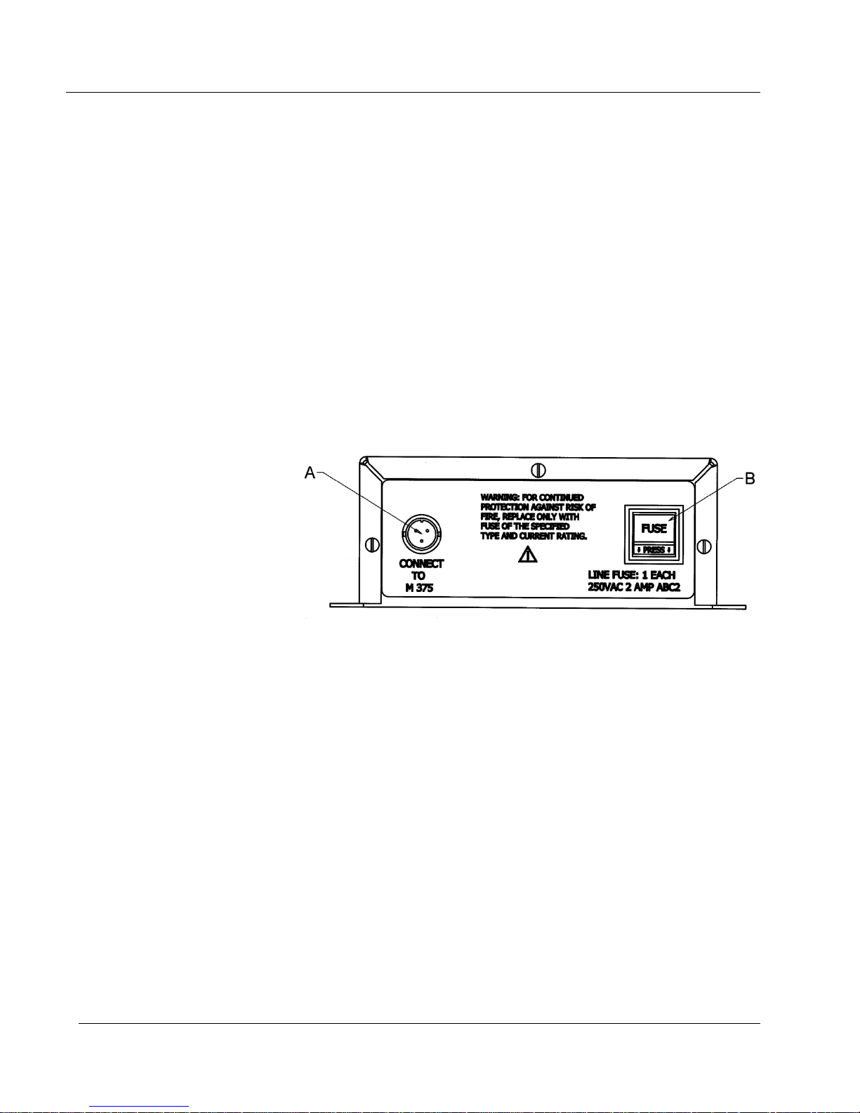
Figure 1. Mains Relay Box Back Panel.
See below for description of noted parts in drawing above.
A – connector for cable (Part # 8303-879) that connects the
mains relay box to the Model 375.
B – Use fuse that is noted in drawing above.
Ludlum Measurements, Inc. Page 5-2 May 2017

Models 375 (Including Series One), 375/1, 375/2 & 375/4 Section 5
Figure 2. Mains Relay Box Front Panel.
See below for description of noted parts in drawing above.
A – conduit connector to the box if necessary.
B – AC receptacle (removed if using conduit).
C – mains relay output 3-pin connectors.
D – optional extra output.
E – relay output for conduit if necessary.
Ludlum Measurements, Inc. Page 5-3 May 2017
Models 375 (Including Series One), 375/1, 375/2 & 375/4 Section 5
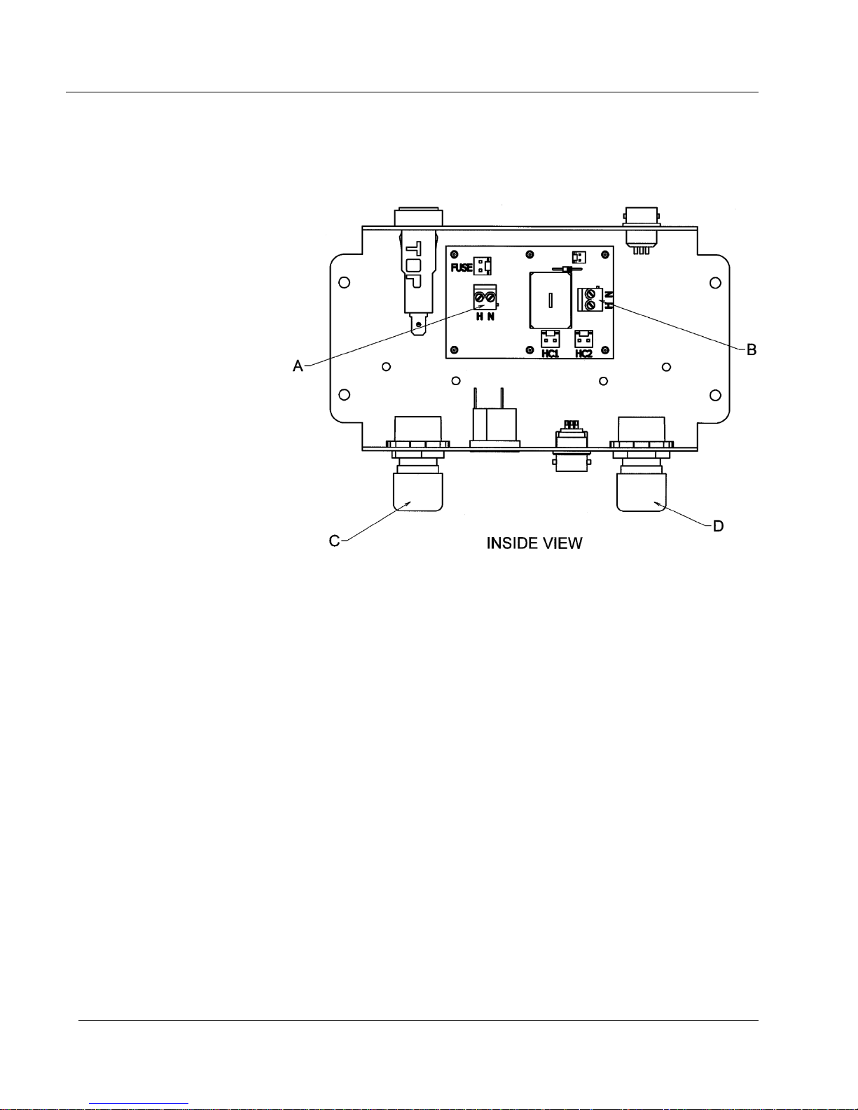
Figure 3. Mains Relay Box Inside View.
See below for description of noted parts in drawing above.
A – 110/220 Vac conduit AC input. “H” = hot and “N” =
neutral. For 220 Vac, H = L1 and N = L2.
B – relay output. “H” = hot and “N” = neutral. For 220 Vac, H
= L1 and N = L2.
C – optional conduit connector input.
D – optional relay output for conduit.
Strobe lights and/or horns are also available through Ludlum
Measurements.
Ludlum Measurements, Inc. Page 5-4 May 2017

Models 375 (Including Series One), 375/1, 375/2 & 375/4 Section 5
Ethernet Interface Option
A 10-BaseT Ethernet interface may be added internally for network
reporting, using Ludlum software:
4558-098 LMI “Ethernet” Hardware Interface
4558-105 LMI “Webpage” Hardware Interface
Either the Ethernet software (1370-055) or the Webpage software (1370-
077) must be purchased separately (site-licensed).
Time and Date Stamp Option
Description:
When an alarm or failure occurs, the Model 375 will print the current
reading, date, time, and either ALARM or FAIL to the RS-232 port. The Model
375 will print once every 30 seconds as long as the alarm or fail condition is
present.
Setup:
You will need the following: a Model 375 instrument, a CBM-910 40-
column printer, and a cable (8558-142).
The printer should be configured at 2400 bps (baud), no parity, 8 data
bits, 1 stop bit, and no handshaking. See printer manual for proper setup
instructions.
Setting the date and time:
Check the month and day (MMDD) by pressing the
HIGH ALARM buttons simultaneously. The month and day will be
LOW ALARM and
displayed as long as those buttons are pressed. The month and day can be
set from 0101 to 1231.
Check the year (YYYY) by pressing the LOW ALARM and CAL CONST
buttons simultaneously. The year will be displayed as long as those
buttons are pressed. The year can be adjusted from 0000 to 9999.
Check the hours and minutes (HHMM) by pressing the
DEAD TIME buttons simultaneously. The hours and minutes will be
displayed as long as those buttons are pressed. The hours and minutes
can be adjusted from 0000 to 2359.
Ludlum Measurements, Inc. Page 5-5 May 2017
LOW ALARM and

Models 375 (Including Series One), 375/1, 375/2 & 375/4 Section 5
RS-232 Data Format:
The data will be sent to the RS-232 port as:
Byte 1 0 x Byte 18 Space (20H)
Byte 2 x x Byte 19 H
Byte 3 x OR x Byte 20 H
Byte 4 x x Byte 21 :
Byte 5 . . Byte 22 M
Byte 6 x 0 Byte 23 M
Byte 7 Space (20H) Byte 24 :
Byte 8 Space (20H) Byte 25 S
Byte 9 Space (20H) Byte 26 S
Byte 10 M Byte 27 Space (20H)
Byte 11 M Byte 28 A Space
Byte 12 / Byte 29 L F
Byte 13 D Byte 30 A OR A
Byte 14 D Byte 31 R I
Byte 15 / Byte 32 M L
Byte 16 Y Byte 33 Carriage Return (0DH)
Byte 17 Y Byte 34 Line Feed (0AH)
Example Output:
0642.1 04/21/95 16:56:24 ALARM
0000.0 04/21/95 08:32:16 FAIL
Printer DIP Switch Settings
Citizen Dot Matrix Printer Model C BM-910 Type II
Please refer to page 32 of the printer user’s manual for the location of the
DIP Switches. Switches 2, 3, and 6 should be in the ON position (toward the
back of the printer). Switches 1, 4, 5, 7, and 8 should be in the OFF position
(toward the front of the printer).
Ludlum Measurements, Inc. Page 5-6 May 2017

Models 375 (Including Series One), 375/1, 375/2 & 375/4 Section 5
Sigma Alarm Modification Option
With this option, special firmware allows the Model 375 to have a sigmabased alarm point in addition to a regular fixed alarm point. This sigmabased alarm point allows the user to have a floating alarm point that will stay
at “x” sigma above the radiation background. As the background changes,
the sigma alarm also changes. The sigma alarm, when activated, activates a
rapid beeping and activates the HIGH ALARM indicator on the front panel of
the Model 375.
To set the sigma alarm, one first needs to consult a probability table showing
one-sided sigma values. If the sigma alarm (read or set by the
button) is set to 3.0, that setting statistically means that 99.87% of normal
background readings would be less than the alarm point. To look at the false
alarm rate, it means that 0.13% or 1 out of 769 comparisons would result in
a false alarm. Since comparisons are made every second, a setting of 3.0 will
result in a false alarm about every 13 minutes. Similarly, a setting of 5.0
would result in a false alarm every 38 days. To actually calculate the sigma
alarm point, it is necessary first to determine the background radiation level
in cps (counts per second). The sigma alarm point is then BKGND + (x
sigma × square root of BKGND).
LOW ALARM
The HIGH ALARM has not been changed; it is still a fixed alarm point and will
be activated when the radiation level exceeds that setpoint. This feature
allows the sigma alarm to trigger quickly if a small amount of radiation is
present and allows the fixed alarm to warn that the background radiation is
too high. Since the sigma alarm is allowed to rise if the background rises, the
HIGH ALARM is necessary to have an absolute value or ceiling for the
radiation level. The time constant for the background radiation level and the
displayed radiation reading is 20 seconds. The sigma alarm is not activated
until 60 seconds after the Model 375 is turned ON, in order to allow the
Model 375 to accumulate a stable background radiation reading.
Two other changes were made to the Model 375. The first change was to
deactivate the
LOW ALARM button) and the fixed alarm (HIGH ALARM button) trigger the
HIGH ALARM indicator. The second change was to lower the detector loss-
LOW ALARM indicator. Both the sigma-based alarm (set by the
of-count time frame to 15 seconds. This change means that the DET FAIL
indicator is activated if no pulses are received from the radiation detectors in
15 seconds. Since the sigma alarm is most useful for scintillation detectors
that have several hundred pulses per minute, this change allows a faster
determination of detector failure.
Ludlum Measurements, Inc. Page 5-7 May 2017
Models 375 (Including Series One), 375/1, 375/2 & 375/4 Section 5
4 to 20 mA Isolated Output Driv er Option
4 to 20 mA Driver (Isolated) Modification Kit Part Number 4558-104
This circuit may be added to replace the Model 375 analog output, providing
an isolated 4 to 20 mA output capability. The circuit board (LMI Part
Number 5396-754) takes the analog output, varying between 0 and 5.00
volts, and converts it to a current output of 4 to 20 mA.
The circuit has an internal loop supply, generating +12 Vdc from the
RAWDC of the Model 375. It is designed for a 2-wire configuration, with
one conductor carrying the 4-20 mA current signal and the second
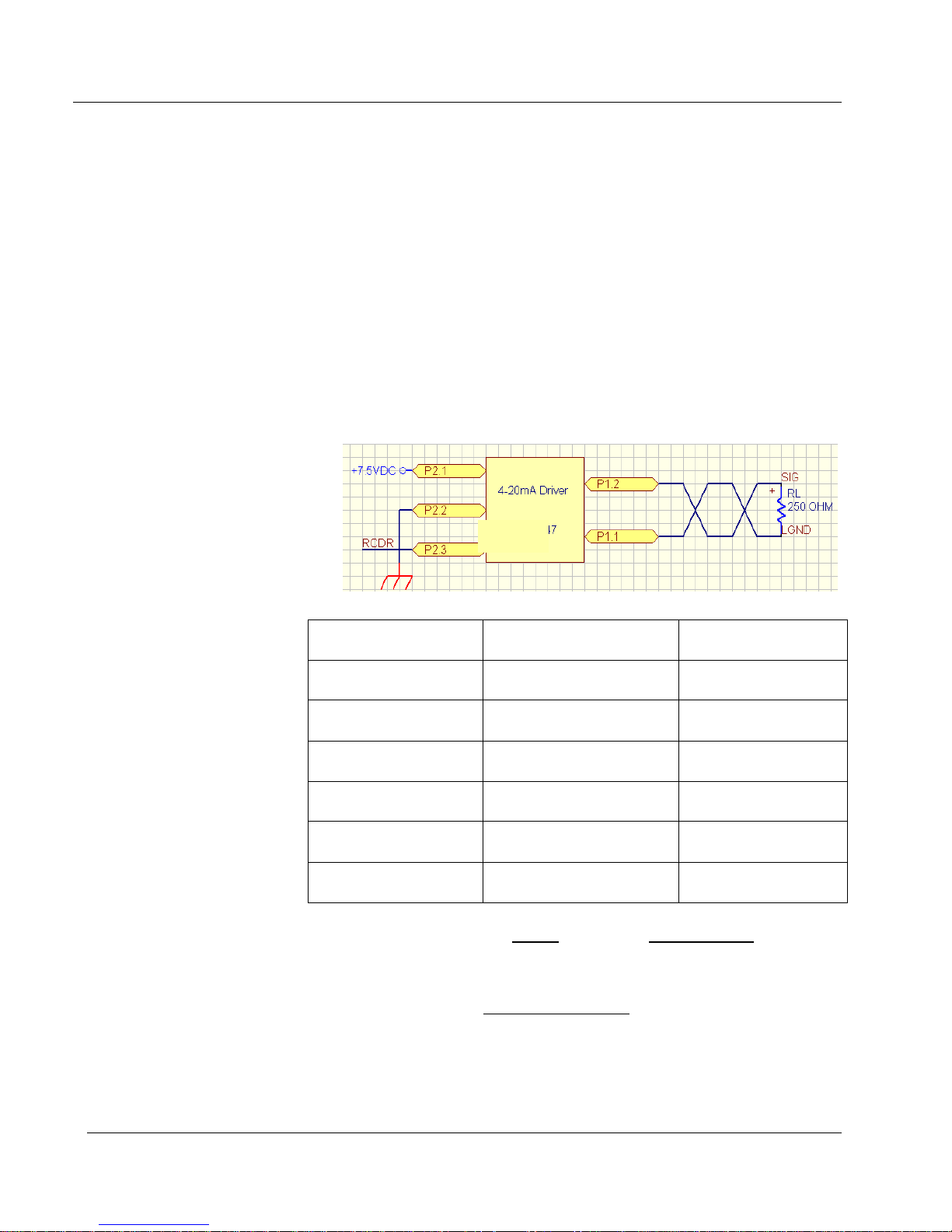
conductor providing a return (isolated loop ground). See Wiring Diagram,
Figure 4 (below).
Figure 4: Wiring Diagram.
5396-754
Decade “Base” Display mA Value
0 0.1 4 mA
1 1 7.2 mA
2 10 10.4 mA
3 100 13.6 mA
4 1000 16.8 mA
5 10,000 20 mA
mA value = 4
.
3.2log
∗
Display reading = 10
.∗
.
Ludlum Measurements, Inc. Page 5-8 May 2017

Models 375 (Including Series One), 375/1, 375/2 & 375/4 Section 5
SPECIFICATIONS
Power Required: 7.5 Vdc at 100 mA; minimum V
maximum Vin= 15 V (connected internally)
Terminating Resistor: 250 ohm
Model 375 4 to 20 mA Isolated Output Connections (3-pin Hirose
connector)
Pin 1 is black (negative).
Pin 2 is white (positive).
Internal Board Header Pinout
P1-1) Loop GND (Isolated)
P1-2) 4-20 current output (Isolated)
P2-1) +7.5 Vdc , RAWDC from main circuit board number 5396-160
(May range from +5.5 to 15 Vdc)
P2-2) GND
P2-3) RCDR voltage in or analog input (0-1.25 Vdc)
= 5.5 V and
in
CALIBRATION
Apply 0 counts or RESET the Model 375.
Check for a voltage of 1.00 V ±5% across Rterm, typically a 250 ohm (V
= 0.004 X Rterm) terminating resistor. The resistor should be placed
between Pin 5 (the 4-20 mA output) and Pin 6 (Loop ground).
Note:
Loop ground is isolated from instrument ground.
Now apply a full-scale meter reading to the analog input, or move the
CAL dipswitch to the right. The voltage at full-scale must be set to 5.00 V
±0.1 V between the analog input and instrument ground.
Note:
Instrument ground is not the same as loop ground.
Adjust the SPAN trimmer, R5, until the voltage across the 250-ohm
terminating resistor is 5 V ±5% (V= .020 X Rtem).
Ludlum Measurements, Inc. Page 5-9 May 2017

Models 375 (Including Series One), 375/1, 375/2 & 375/4 Section 6
Section
6
Safety Considerations
Environmental Conditions for Normal Use
Indoor use only
No maximum altitude
Temperature range of -15 to 50 °C (5 to 122 °F); may be certified for
operation from -40 °C (-40 °F)
Maximum relative humidity of less than 95% (non-condensing)
Mains supply voltage range of 100-240 Vac ,
50/60Hz single phase (less than 100 mA typical, 1 amp max) to wallmounted DC adapter supplying 9-12 Vdc
Maximum transient voltage of 1500 Vac
Installation Category II (Overvoltage Category as defined by IEC 1010-1)
Pollution Degree 2 (as defined by IEC 664)
Cleaning Instructions and Precautions
The Model 375 may be cleaned externally with bleach wipes or with a damp
cloth, using water, Lysol or alcohol as a wetting agent. Do not immerse the
instrument in any liquid. Observe the following precautions when cleaning:
1. Turn the instrument OFF and disconnect the instrument power
cord.
2. Allow the instrument to sit for one minute before cleaning.
Ludlum Measurements, Inc. Page 6-1 May 2017

Models 375 (Including Series One), 375/1, 375/2 & 375/4 Section 6
Warning Markings and Symbols
Caution!
The operator or responsible body is cautioned that the
protection provided by the equipment may be impaired if
the equipment is used in a manner not specified by Ludlum
Measurements, Inc.
The Model 375 is marked with the following symbols:
CAUTION, RISK OF ELECTRIC SHOCK (per ISO 3864, No. B.3.6)
– designates a terminal (connector) that allows connection to a voltage
exceeding 1 kV. Contact with the subject connector while the instrument is
on or shortly after turning off may result in electric shock. This symbol
appears on the side panel (Applicable for Models with an external detector).
DIRECT CURRENT (DC) (IEC 417, No. 5032) - designates an input
receptacle that accommodates a power cord intended for connection to DC
voltages. This symbol appears on the side panel.
PROTECTIVE CONDUCTOR TERMINAL (per IEC 417, No. 5019)
– designates the central grounding point for the safety ground. This symbol
is visible inside the chassis.
CAUTION (per ISO 3864, No. B.3.1) – designates hazardous live voltage
and risk of electric shock. During normal use, internal components are
hazardous live. This instrument must be isolated or disconnected from the
hazardous live voltage before accessing the internal components. This
symbol appears on the side panel. Note the following precautions:
Caution!
Do no touch the circuit board in the calibration window due
to possible electric shock.
Caution!
Verify instrument voltage input rating before connecting to a
power converter. If the wrong power converter is used, the
instrument and/or power converter could be damaged.
Ludlum Measurements, Inc. Page 6-2 May 2017
Models 375 (Including Series One), 375/1, 375/2 & 375/4
Warning!
Section 6
The operator is strongly cautioned to take the following
precautions to avoid contact with internal hazardous live parts
that are accessible using a tool:
1. Turn the instrument power
OFF
and disconnect the power
cord.
2. Allow the instrument to sit for one minute before accessing
internal components.
The “crossed-out wheelie bin” symbol notifies the consumer that the
product is not to be mixed with unsorted municipal waste when discarding;
each material must be separated. See section 8, “Recycling” for further
information. Also displayed on the side panel.
The “CE” mark is used to identify this instrument as being acceptable for
use within the European Union.
Electrical Safety Precautions
Warning!
Observe the following instructions to avoid a potentially
hazardous situation which, if mishandled, could result in
death or serious personal injury, as well as property damage.
Do not expose the unit to rain or an environment where it may be
splashed by water or other liquids, as doing so may result in fire or
electric shock.
Use the unit only with the voltage specified on the unit. Using a
voltage higher than that which is specified may result in fire or
electric shock.
Do not cut, kink, or otherwise damage nor modify the power supply
cord. IN addition, avoid using the power cord in close proximity to
heaters, and never place heavy objects – including the unit itself –
on the power cord, as doing so may result in fire or electric shock.
Avoid installing or mounting the unit or its power supply in unstable
conditions, such as a rickety table or a slanted surface. Doing so may
Ludlum Measurements, Inc. Page 6-3 May 2017

Models 375 (Including Series One), 375/1, 375/2 & 375/4 Section 6
result in the unit falling down and causing personal injury and/or
property damage.
Replacement of Main Fuse (Side Panel)
Warning!
For continued protection against risk of fire, replace only
with fuse of the specified type and current rating.
Detector Connector
Warning!
Potential electrical shock hazard: do not touch the center pin
of the detector connector unless the unit has turned off and
power has been removed for at least one minute.
Battery Replacement
Warning!
Only certified technicians or calibration personnel should
replace battery.
Ludlum Measurements, Inc. Page 6-4 May 2017

Models 375 (Including Series One), 375/1, 375/2 & 375/4 Section 7
Section
7
Calibration
High V oltage
The high voltage is adjustable from 450-2500 Vdc using the HV
potentiometer located under the calibration cover. The high voltage required
will depend on the type of detector used. Internal GM detectors usually
require 550 Vdc. Ensure that the high voltage is checked only with a highimpedance (≥1000 megohm) voltmeter. A high-voltage checkpoint is
located next to the HV potentiometer.
Warning!
Do not touch the circuit board in the calibration window
due to potential for electric shock.
Calibration Parameters
The calibration parameters, LOW ALARM, HIGH ALARM, CAL CONST, and
DEAD TIME can only be changed while in calibration mode. Switch the top
dipswitch CAL MODE to the right to switch into calibration mode. Changing
any parameter is done by holding down the parameter key and pressing the
up or down arrow buttons. Any parameter can be set in the range of 0.1 to
9999*. If a parameter is changed, the instrument will beep to confirm the
saving of the parameter, and then return to displaying the current radiation
level.
The calibration constant (
a "low" radiation field. A "low" radiation field in this case is defined as a field
where dead time losses do not exceed 5%. The calibration constant is usually
given for a certain detector. A Ludlum Model 133-4 detector, for example,
has a calibration constant of approximately 100 cpm/mR/hr. Once the
calibration constant is set and checked at a low radiation field, the dead time
correction can be set.
Ludlum Measurements, Inc. Page 7-1 May 2017
CAL CONST) is set when the detector is exposed to

Models 375 (Including Series One), 375/1, 375/2 & 375/4 Section 7
The dead time correction (DEAD TIME) is set when the detector is exposed to a
"high" radiation field. A "high" radiation field in this case is defined as a field
where dead time losses exceed 30%. The dead time correction will elevate the
ratemeter reading to account for counts arriving at the detector during the
detector's dead time. GM tubes typically have long dead times from 50-150
microseconds. Neutron and scintillation detectors generally have short dead times
of 1-5 microseconds.
Note:
Once parameters are set, it is important to remember to
switch the CAL MODE switch back to the left. This action
protects the parameters from inadvertent changes.
Analog Output
The analog output is a five-decade logarithmic voltage-out. The maximum
voltage-out while under primary power is 6 volts. The maximum voltage-out
while under battery backup power is 4.5 volts. The five decades are:
0.1 <units> - 1.0 <units>*
1 <units> - 10 <units>*
10 <units> - 100 <units>*
100 <units> - 1000 <units>*
1000 <units> - 10000 <units>*
When the CAL MODE dip switch is switched to the right, the analog output
goes to full scale. The analog output goes to full scale during a DET FAIL
condition.
Discriminator
The DISC potentiometer located under the calibration cover is used to set the
threshold for pulses coming from the detector. The desired pulse threshold
depends on the type of detector used. It is adjustable from 2.0 mVdc to 100
mVdc.
Battery Charge
The potentiometer labeled BAT, located under the calibration cover, is used
to set the backup battery trickle-charge voltage. This is typically set to 6.9
Vdc with the battery disconnected.
* See note on page 2-3 regarding Model 375 Series One.
Ludlum Measurements, Inc. Page 7-2 May 2017

Models 375 (Including Series One), 375/1, 375/2 & 375/4
Section 8
Section
8
Recycling
udlum Measurements, Inc. supports the recycling of the electronics
products it produces for the purpose of protecting the environment
L
recycling systems. To this end, Ludlum Measurements, Inc. strives to supply
the consumer of its goods with information regarding reuse and recycling of
the many different types of materials used in its products. With many
different agencies – public and private – involved in this pursuit it becomes
evident that a myriad of methods can be used in the process of recycling.
Therefore, Ludlum Measurements, Inc. does not suggest one particular
method over another, but simply desires to inform its consumers of the
range of recyclable materials present in its products, so that the user will
have flexibility in following all local and federal laws.
The following types of recyclable materials are present in Ludlum
Measurements, Inc. electronics products, and should be recycled separately.
The list is not all-inclusive, nor does it suggest that all materials are present in
each piece of equipment:
and to comply with all regional, national, and international agencies
that promote economically and environmentally sustainable
Batteries Glass Aluminum and Stainless Steel
Circuit Boards Plastics Liquid Crystal Display (LCD)
Ludlum Measurements, Inc. products, which have been placed on the
market after August 13, 2005, have been labeled with a symbol recognized
internationally as the “crossed-out wheelie bin.” This notifies the consumer
that the product is not to be mixed with unsorted municipal waste when
discarding; each material must be separated. The symbol will be placed near
the AC receptacle, except for portable equipment where it will be placed on
the battery lid.
The symbol appears as such:
Ludlum Measurements, Inc. Page 8-1 May 2017

Models 375 (Including Series One), 375/1, 375/2 & 375/4 Section 9
Section
9
Model 375 Digital WallMount Area Monitor
without Detector
Model 375/1 Digital WallMount Area Monitor
Model 375/2 Digital WallMount Area Monitor
Model 375/4 Digital WallMount Area Monitor
Model 375 Series One
without Detector
Model 375/2 Series One
Model 375/4 Series One
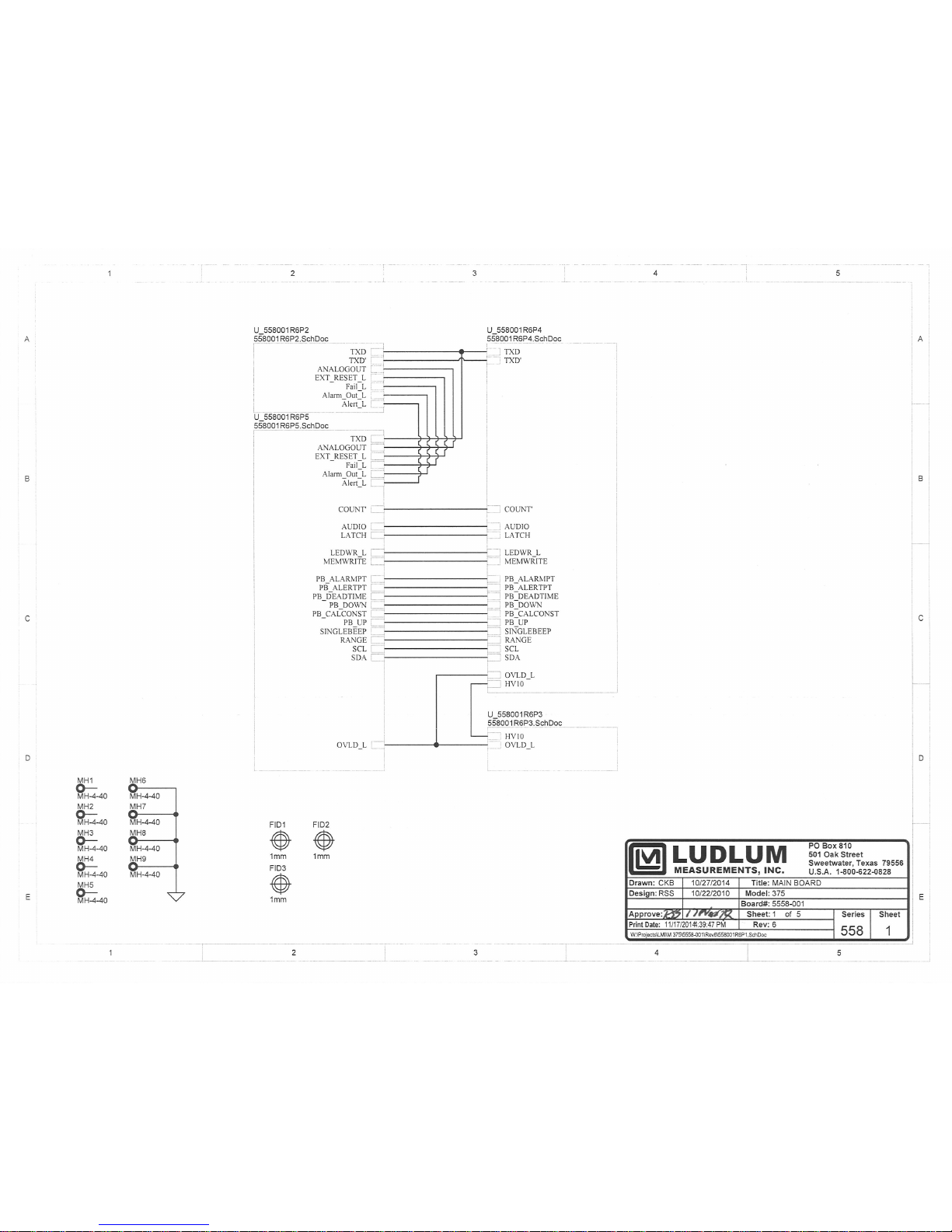
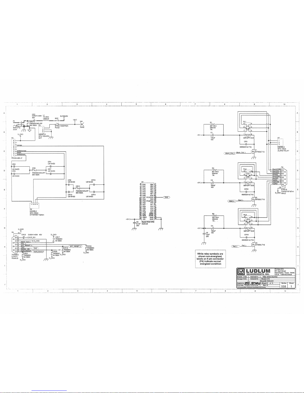
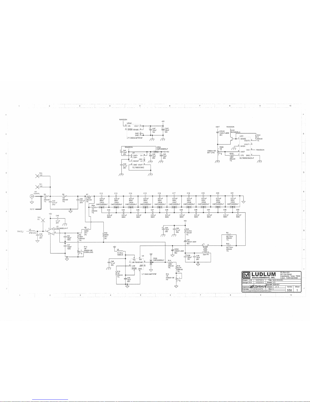
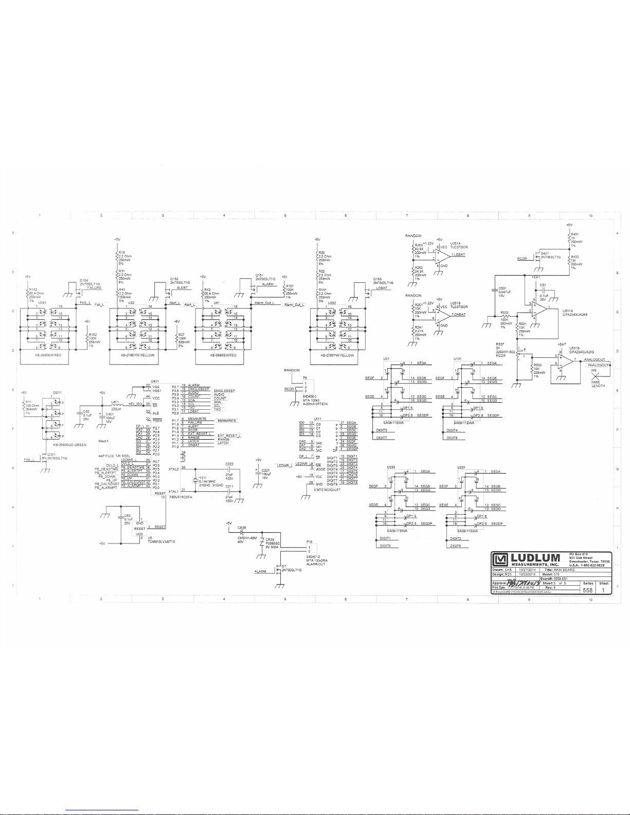
Main Board,
Drawing 558 x 1
CRYSTAL
CAPACITORS
Parts List
Reference Description Part Number
UNIT Completely Assembled 48-2230
Model 375
UNIT Completely Assembled 48-3831
Model 375/1
UNIT Completely Assembled 48-2410
Model 375/2
UNIT Completely Assembled 48-2411
Model 375/4
UNIT Completely Assembled 48-2676
Model 375 Series One
UNIT Completely Assembled 48-2931
Model 375/2 Series One
UNIT Completely Assembled 48-3007
Model 375/4 Series One
BOARD Completely Assembled Main 5558-001
Circuit Board (common to all)
Y211 6.144 MHZ 01-5262
C1-C2 100µF, 16V 04-5794
C3 0.1µF, 25V 04-5744
C4 100µF, 16V 04-5794
C5-C6 10µF, 25V 04-5728
C7 100µF, 16V 04-5794
C8 10µF, 25V 04-5728
Ludlum Measurements, Inc. Page 9-1 May 2017

Models 375 (Including Series One), 375/1, 375/2 & 375/4 Section 9
T
Reference Description Part Number
C9-C11 100µF, 16V 04-5794
C12-C21 0.1µF, 500V 04-5696
C22-C23 0.01µF, 3kV 04-5762
C24-C33 0.1µF, 500V 04-5696
C35 100pF, 100V 04-5743
C36 10µF, 25V 04-5728
C37 100pF, 100V 04-5743
C38 100µF, 16V 04-5794
C39-C40 10µF, 25V 04-5728
C41-C43 10µF, 25V 04-5655
C44-C53 0.1µF, 25V 04-5744
C54 10µF, 25V 04-5655
C55-C56 0.1µF, 25V 04-5744
C57 4.7pF, 200V 04-5787
C201 10µF, 25V 04-5655
C211 27pF, 100V 04-5658
C221 100µF, 16V 04-5794
C222 27pF, 100V 04-5658
C301-C303 10µF, 25V 04-5655
C401 100µF, 16V 04-5794
C441-C442 100µF, 16V 04-5794
C531 0.047µF, 16V 04-5729
C541-542 10µF, 25V 04-5655
C543 2700µF, 35V 04-5621
C611 10µF, 25V 04-5655
C711-C12 10µF, 25V 04-5655
C721 10µF, 25V 04-5655
C722 0.001µF, 100V 04-5659
C731 100pF, 3kV 04-5735
RANSISTORS
VOLTAGE
REGULATOR
Q1-Q3 2N7002L 05-5840
Q4 CMXT3904TRLF 05-5888
Q5 CMXT-3906TRLF 05-5890
Q6 CMXT3904TRLF 05-5888
Q7 2N7002L 05-5840
Q151-Q154 2N7002L 05-5840
Q321-Q322 2N7002L 05-5840
Q331 MJD200RLG 05-5844
Q431 2N7002L 05-5840
VR341 LT1129CQ-5 06-6372
Ludlum Measurements, Inc. Page 9-2 May 2017

Models 375 (Including Series One), 375/1, 375/2 & 375/4 Section 9
Reference Description Part Number
INTEGRATED
CIRCUITS
DIODES
U2 MAX985EUK+T 06-6459
U3 LT1304CS8 06-6394
U4 ICL7660SCBAZ 06-6437
U5 TCM810LVNB713 06-6424
U31 SA08-11EWA 07-6389
U32 KB-2785YW 07-6371
U41 KB-2685EW 07-6400
U111 ICM7218CIQI-LFT 06-6311
U131 SA08-11EWA 07-6389
U201 MAX220ESE+T 06-6329
U231 SA08-11EWA 07-6389
U232 KB-2785YW 07-6371
U233 SA08-11EWA 07-6389
U241 KB-2685EW 07-6400
U251 TLC372IDR 06-6290
U321 M24C02-WMN6TP 06-6299
U331 ICL7663SCBAZA-T 06-6302
U411 P89V51RD2FA 06-6303
U521 CD74HC4538M96 06-6297
U531 OPA2343UA2K5 06-6582
U611 MAX985EUK+T 06-6459
U711 LM285DR-1-2 05-5845
CR1 CMSH1-40M 07-6411
CR2 P0640SCMCLRP 21-9028
CR3 MMBD914LT1G 07-6353
CR4-CR5 US1M-E3 07-6530
CR6 P0640SCMCLRP 21-9028
CR7-CR10 US1M-E3 07-6530
CR11 P0640SCMCLRP 21-9028
CR12 MMBD914LT1G 07-6353
CR13-CR14 US1M-E3 07-6530
CR15 CMSH1-40M 07-6411
CR16 MMBD914LT1G 07-6353
CR17-CR21 P0080SC 21-9004
CR22-CR31 CMPD2005SLF 07-6468
CR32 CMSH1-40M 07-6411
CR33-CR34 CMPD2005SLF 07-6468
CR35 CMSH1-40M 07-6411
CR36 P0080SC 21-9004
CR38 US1M-E3 07-6530
CR341-CR342 CMSH1-40M 07-6411
Ludlum Measurements, Inc. Page 9-3 May 2017

Models 375 (Including Series One), 375/1, 375/2 & 375/4 Section 9
LED
SWITCHES
POTENTIOMETER
RESISTORS
DS11 KB-2550SGD 07-6370
S001 ALERT POINT 08-6728
S101 ALARM POINT 08-6728
S201 CALIBRATION CONSTANT 08-6728
S301 DEADTIME CORRECTION 08-6728
S501 DOWN 08-6728
S511 UP 08-6728
S512 OPTION DIPSWITCH 08-6709
SW1 POWER 08-6840
R13 1M, BAT CHG ADJ 09-6778
R16 1M, HV ADJ 09-6778
R523 1M, OVLD ADJ 09-6778
R535 200K, THR ADJ 09-6949
R537 5K, RCDR 09-6849
R1-R4 301ohm, 1%, 250mW 12-7863
R5-R6 1M, 1%, 250mW 11-7251
R7 4.75M, 1%, 250mW 12-7995
R8 500M, 2%, 3kV 12-7031
R9 165K, 1%, 125mW 12-7877
R10 500M, 2%, 3kV 12-7031
R11 100ohm, 1%, 250mW 12-7840
R12 301ohm, 1%, 250mW 12-7863
R14 165K, 1%, 250mW 12-7877
R15 1M, 1%, 250mW 11-7251
R17 2.2ohm, 5%, 250mW 12-7932
R18 82.5K, 1%, 250mW 12-7849
R19-R22 2.2ohm, 5%, 250mW 12-7932
R23 100K, 1%, 250mW 12-7834
R24 1M, 1%, 250mW 11-7251
R25 10ohm, 1%, 125mW 12-7836
R26 100ohm, 1%, 100mW 12-7142
R27 100k, 5%, 333mW 12-7747
R41 2.2ohm, 5%, 250mW 12-7932
R42 60.4ohm, 1%, 250mW 12-7962
R141 2.2ohm, 5%, 250mW 12-7932
R142 60.4ohm, 1%, 250mW 12-7962
R151-R152 100K, 1%, 250mW 12-7834
R201 24.3K, 1%, 250mW 12-7867
R241 2.21K, 1%, 250mW 12-7835
R251 10K, 1%, 250mW 12-7839
R252 24.3K, 1%, 250mW 12-7867
Ludlum Measurements, Inc. Page 9-4 May 2017

Models 375 (Including Series One), 375/1, 375/2 & 375/4 Section 9
R253 82.5K, 1%, 250mW 12-7849
R331 1K, 1%, 250mW 12-7832
R332 165K, 1%, 250mW 12-7877
R341 2.2ohm, 5%, 250mW 12-7932
R431 1K, 1%, 250mW 12-7832
R421-R422 100K, 1%, 250mW 12-7834
R432 1M, 1%, 250mW 11-7251
R531 10K, 1%, 250mW 12-7839
R532 100K, 1%, 250mW 12-7834
R533 10K, 1%, 250mW 12-7839
R534 2.21K, 1%, 250mW 12-7835
R611 47.5K, 1%, 250mW 12-7872
R621 4.75K, 1%, 250mW 12-7858
R622 10K, 1%, 250mW 12-7839
R623 1K, 1%, 250mW 12-7832
R631 47.5K, 1%, 250mW 12-7872
R713-R714 10K, 1%, 250mW 12-7839
R721 10K, 1%, 250mW 12-7839
R722 165K, 1%, 250mW 12-7877
R723 1K, 1%, 250mW 12-7832
R724 4.75K, 1%, 250mW 12-7858
R732-R733 100K, 1%, 250mW 12-7834
R735 10K, 1%, 250mW 12-7839
RESISTOR NETWORK
CONNECTOR
RN411 220K 12-7831
P1 RAPC712 13-8445
P2 640457-3 BAT 13-8165
P3 FRJAE-468 LF 21-9007
P4 9 PIN D CONN-747197-4 13-8364
P5 640456-3 MTA 100X4 ETHERNET
13-8088
P6 747020-2 9 PIN D FEMALE 13-8555
P7 640456-3 MTA 100X3 4-20mA 13-8081
P8 640457-4 MTA 100X4RA SONALERT
13-8089
P9 640456-3 MTA 100X3 4-20mA 13-8081
P10 640457-2 MTAX2RA ALARM OUT
13-8147
Ludlum Measurements, Inc. Page 9-5 May 2017

Models 375 (Including Series One), 375/1, 375/2 & 375/4 Section 9
Reference Description Part Number
INDUCTORS
RELAY
TRANSFORMER
MISCELLANEOUS
Wiring Diagram,
Drawing 558 x 136
AUDIO
FUSE
BATTERY
Internal Detectors
L1 1Kohm 21-9008
L3-L4 2700ohm 21-9009
L8 2700ohm 21-9009
L9 1Kohm 21-9008
L411 220µHY 21-9678
RL1-RL3 G6K-2FY DC5 22-9332
T1 32377R 21-9925
* SOCKET 44P PLCC 06-6613
S2 SHIELD-M4500 PREAMP 7436-142
U1 RABBIT RCM 3700 23110915
W1 COAX, WIRE *
W3-W5 WIRE *
TP1-TP3 COAX, WIRE *
DS1 TXC-V86-515-Q
WARNING DEVICE 218802
F1 RUEF110, 1.1A, 30V 21-8989
B1 BATTERY-PS630 21-9705
* Model 375/2 (only) DET ASSY. 4396-055
* Model 375/4 (only) DET ASSY. 4396-056
Ludlum Measurements, Inc. Page 9-6 May 2017

Models 375 (Including Series One), 375/1, 375/2 & 375/4 Section 10
Section
10
Drawings
Main Circuit Board, Drawing 558 x 1 (5 sheets)
Main Circuit Board Component Layout Drawing 558 x 2
Main Circuit Board Component Layout Drawing 558 x 2A
Wiring Diagram, Drawing 558 x 136
Ludlum Measurements, Inc. Page 10-1 May 2017


 Loading...