


LUDLUM MODELS 2401-ECA,
2401-EWA, 2401-EC2A AND 2401-PA
POCKET SURVEY METERS WI TH A LARM
September 2011
Serial Number 143446 and Succeeding
Serial Numbers

LUDLUM MODELS 2401-ECA,
2401-EWA, 2401-EC2A AND 2401-PA
POCKET SURVEY METERS WI TH A LARM
September 2011
Serial Number 143446 and Succeeding
Serial Numbers

STATEMENT OF WARRANTY
Ludlum Measurements, Inc. warrants the products covered in this manual to be free of
defects due to workmanship, material, and design for a period of twelve months from the
date of delivery. The calibration of a product is warranted to be within its specified
accuracy limits at the time of shipment. In the event of instrument failure, notify Ludlum
Measurements to determine if repair, recalibration, or replacement is required.
This warranty excludes the replacement of photomultiplier tubes, G-M and proportional
tubes, and scintillation crystals which are broken due to excessive physical abuse or used
for purposes other than intended.
There are no warranties, express or implied, including without limitation any implied
warranty of merchantability or fitness, which extend beyond the description of the face
there of. If the product does not perform as warranted herein, purchaser’s sole remedy
shall be repair or replacement, at the option of Ludlum Measurements. In no event will
Ludlum Measurements be liable for damages, lost revenue, lost wages, or any other
incidental or consequential damages, arising from the purchase, use, or inability to
product
.
use
RETURN OF GOODS TO MANUFACTURER
If equipment needs to be returned to Ludlum Measurements, Inc. for repair or calibration, please send to
the address below. All shipments should include documentation containing return shipping address,
customer name, telephone number, description of service requested, and all other necessary information.
Your cooperation will expedite the return of your equipment.
ATTN: REPAIR DEPARTMENT
501 OAK STREET
SWEETWATER, TX 79556
LUDLUM MEASUREMENTS, INC.
800-622-0828 325-235-5494
FAX 325-235-4672

Table of Contents
Introduction 1
Getting Started 2
Battery Installation 2-1
Battery Test 2-1
Instrument Test 2-1
Operational Check 2-2
Specifications 3
Identification of Controls and Functions 4
Safety Considerations and Maintenance 5
Environmental Conditions for Normal Use 5-1
Warning Markings and Symbols 5-1
Mica Window Precaution 5-2
Cleaning and Maintenance Precautions 5-2
Maintenance 5-3
Recalibration 5-3
Slide Switches 5-3
Radiation Basics 6
Radiation and Life 6-1
The Unstable Atom 6-2
Radioactive Decay 6-3
Ionizing Radiation 6-4
Measuring Ionizing Radiation 6-5
What are the Health Risks from Ionizing Radiation? 6-6
How Much Ionizing Radiation is Dangerous? 6-7
Background Radiation 6-10
Manmade Radiation 6-11
Protection from Radiation 6-11
Standards and Regulation 6-12
Who is in Charge? 6-12
Ludlum Measurements, Inc. September 2011

MODELS 2401-ECA, 240 1-EWA, 2401-EC2A & 2401-PA
Recycling 7
Parts List 8
Models 2401-ECA, 2401-EWA, 2401-EC2A Survey Meters 8-1
Main Board, Drawing 397 × 87 8-1
Model 2401-PA Survey Meter 8-4
Main Board, Drawing 397 × 190 8-4
Drawings and Diagrams 9
Ludlum Measurements, Inc. September 2011

MODELS 2401-ECA, 240 1-EWA, 2401-EC2A & 2401-PA Section 1
Section
1
T
Introduction
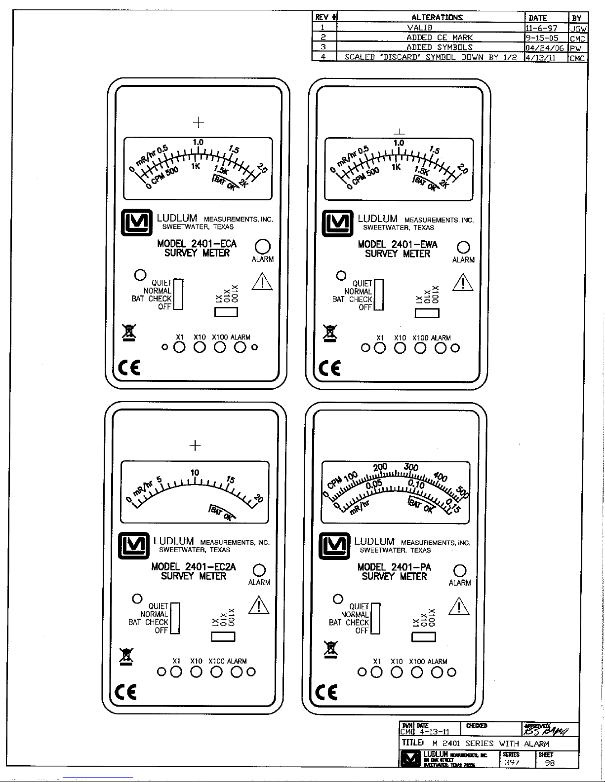
he Model 2401 alarming series of hand-held or “pocket” radiation
survey instruments are designed to quickly and easily measure
ionizing radiation. Different types are available featuring different
internal detectors. These types are distinguished from one another
by a suffix following the “Model 2401” designation. The units are selfcontained and require no external accessories.
This manual applies to the following instruments in the Model 2401 Series
of Pocket Radiation Survey Meters with Alarm:
Model 2401-ECA - contains an energy-compensated Geiger-Mueller
(GM) tube detector, which measures low levels of gamma radiation.
One or two measurement scales are provided on the meter face (in
addition to the BAT OK range). If two scales are provided, they indicate
exposure rate and count rate. Examples of exposure rate units are
mR/hr and mSv/h, while count rate may be measured in counts per
minute (cpm) or counts per second (cps).
Model 2401-EWA - has a thin end-window, GM tube detector that
measures alpha, beta, and gamma radiation. The mica window has a
thickness (window area density) of 1.5 to 2.0 mg/cm2. Two
measurement scales may be provided on the meter face as described
above.
Model 2401-EC2A - contains an energy-compensated GM tube detector.
This is basically the same as the Model 2401-ECA, with the capability of
measuring higher levels of gamma radiation with corresponding
measurement scales.
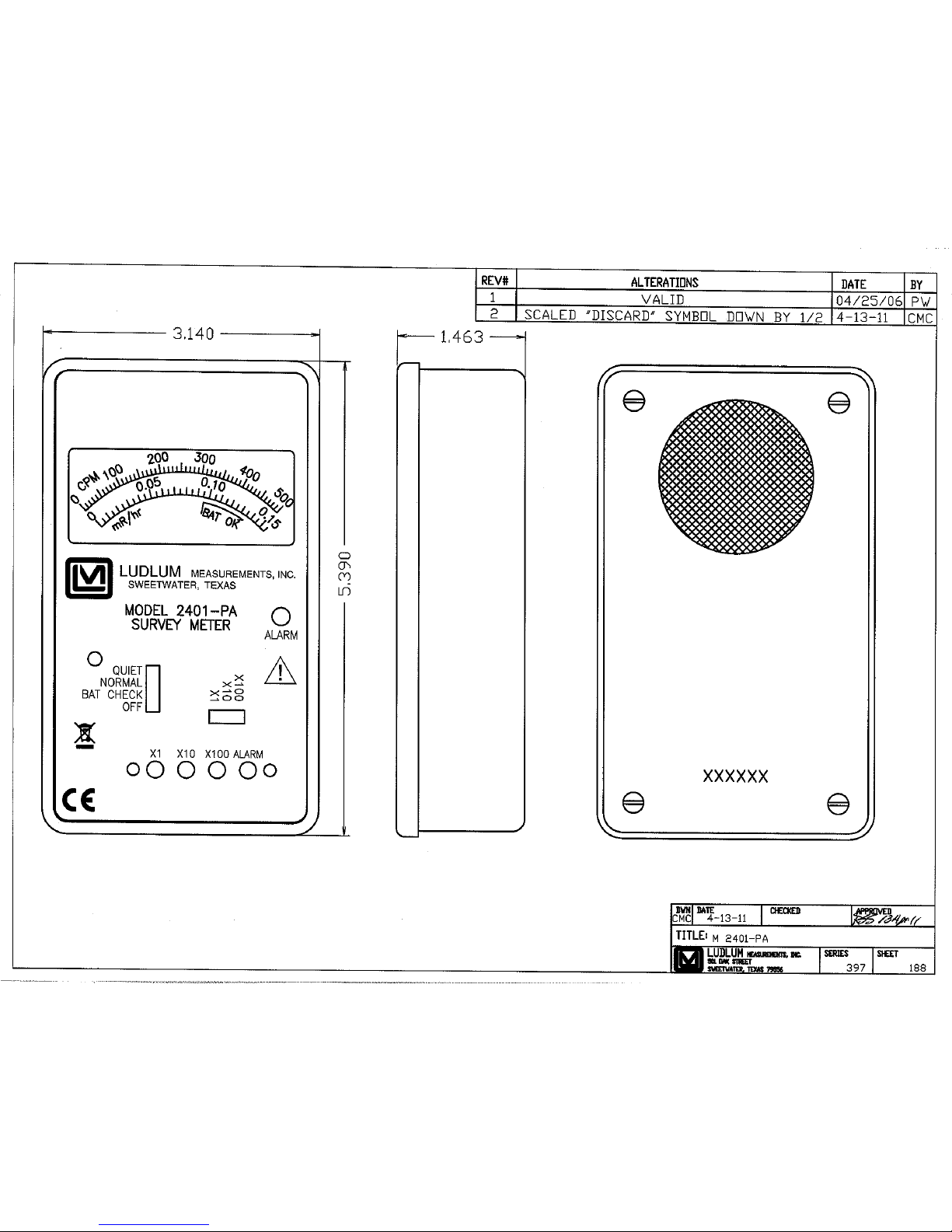
Model 2401-PA- employs a full-size “pancake” tube detector (5.1 cm {2
in.} diameter) that can measure alpha, beta, and gamma radiation. One
or two measurement scales may be provided on the meter face in units
Ludlum Measurements, Inc. Page 1-1 September 2011
of exposure rate and/or count rate as described above.

MODELS 2401-ECA, 240 1-EWA, 2401-EC2A & 2401-PA Section 1
Each instrument in the Model 2401 series has a large 6.4 cm (2.5 in.) analog
meter for displaying the radiation level. A three-decade range switch allows
the user to switch among the three ranges (×1, ×10 and ×100). A BAT
CHECK
level. A QUIET position allows the user to turn the click-per-event audio off.
Activation of a red ALARM LED and steady tone from the audio speaker
indicate an alarm condition when the displayed radiation level has exceeded
the set alarm point.
A 9-volt battery powers the unit. Battery life is typically 250 hours at normal
background levels. A steady tone from the audio speaker (whether in
NORMAL or QUIET mode) indicates that the battery needs to be changed;
proper instrument operation is not guaranteed until the battery is replaced.
position on the selector switch allows the meter to show the battery
Ludlum Measurements, Inc. Page 1-2 September 2011

MODELS 2401-ECA, 2401-EWA, 2401-EC2A & 2401-PA Section 2
Section
2
Getting Started
Battery Installation
Ensure the instrument selector switch is in the OFF position. Remove the
four screws from the back side of the instrument and remove the back
housing. Place a 9-volt battery in the battery holder and press the battery
onto battery terminals. Replace the instrument housing and screws.
Caution!
Damage to the mica window on the top of the Model 2401EWA and on the back side of the Model 2401-PA may result
if careful instrument handling is not practiced. The window is
very fragile and may be punctured quite easily.
Battery Test
The battery should be checked each time the instrument is turned on. Slide
the selector switch to the BAT CHECK position. Ensure that the meter needle
deflects to the battery check portion on the meter scale. If the meter does
not respond, check to see if the battery has been correctly installed. Replace
the battery if necessary.
Instrument T est
After checking the battery, slide the instrument selector switch to the
NORMAL position. Slide the range switch to the ×1 position. A small meter
needle deflection will likely occur due to normal background radiation. If the
meter needle deflects past full-scale slide the range switch to the next highest
range until a reading can be determined. The amount of deflection will
depend upon the particular series of instrument (due to meter scale
differences) and the amount of normal background radiation. The
instrument speaker should emit a frequency (clicks) relative to the increase in
meter reading.
Ludlum Measurements, Inc. Page 2-1 September 2011

MODELS 2401-ECA, 2401-EWA, 2401-EC2A & 2401-PA Section 2
Read and then remove the sticker (illustrated to the left) from the
instrument. Setting of the alarm point is described in Section 4 of
this manual. The factory setting of the alarm point is noted on the
calibration sheet provided with the instrument.
Place the instrument selector switch in the QUIET position and
note that the audible clicks are silenced. In order to preserve
battery life, it is recommended that the instrument selector switch
be kept in the QUIET position when the audio function is not
needed.
While in an area of normal background radiation, expose the center of the
detector to a check source. Ensure the check source reading is within 20%
of the reference reading obtained during the last calibration.
Note:
The crosshairs above the meter on the black, front panel
indicate the location of the center of the detector. The
exception to this is with the Model 2401-P where the center of
the detector is visible on the back side of the instrument.
If possible, and if not already activated in the previous step, place the range
switch in the ×1 position and check for proper function of the alarm
indicators by placing the check source in such a way as to drive the meter
needle above the alarm set point.
Once this procedure has been completed, the instrument is ready for use.
Operational C heck
To assure proper operation of the instrument between calibrations and
periods of nonuse, an instrument operational check, including battery test
and instrument test (as described above), should be performed prior to use.
A reference reading with a check source should be obtained at the time of
initial calibration, or as soon as possible, for use in confirming proper
instrument operation. In each case, ensure a proper reading on each scale. If
the instrument fails to read within 20% of a proper reading, it should be sent
to a calibration facility for recalibration.
Ludlum Measurements, Inc. Page 2-2 September 2011

MODELS 2401-ECA, 240 1-EWA, 2401-EC2A & 2401-PA Section 3
Section
3
Specifications
0
Detector Tubes: GM tubes with different characteristics for various
models, as follows:
Model 2401-ECA: energy-compensated tube; gamma
Model 2401-EWA: end-window tube; alpha, beta, gamma
Model 2401-EC2A: energy-compensated tube; gamma
Model 2401-PA: standard 5.1 cm (2 in.) diameter
pancake tube; alpha, beta, gamma
Sensitivity: typical values with a
Model 2401-ECA: 1050 cpm per mR/hr
Model 2401-EWA: 1050 cpm per mR/hr
Model 2401-EC2A: 120 cpm per mR/hr
Model 2401-PA: 3300 cpm per mR/hr
Energy Response:
Model 2401-ECA: within 20% of true value from 60 keV
to 3 MeV
Model 2401-EWA: energy dependent
Model 2401-EC2A: within 20% of true value from 60 keV
to 3 MeV
137
Cs source, as follows:
Operating Voltage: typically 550 Vdc for peanut tube detectors (as in
Ludlum Measurements, Inc. Page 3-1 September 2011
Models 2401-ECA, 2401-EWA, and 2401-EC2A); 900 Vdc for pancake
tube detector (as in the Model 2401-PA)
Model 2401-PA: energy dependent

MODELS 2401-ECA, 240 1-EWA, 2401-EC2A & 2401-PA Section 3
Power: one 9-volt battery; typical life is 250 hours at normal
background radiation levels
Response Time: typically 11 seconds or less from 10% to 90% of the
final reading
Accuracy: within 10% of true reading
Meter: 6.4 cm (2.5 in.) arc, 1 mA rugged analog meter
Calibration Controls
: Located underneath the calibration cover on the
front panel, these potentiometers allow adjustment of the ×1, ×10, and
×100 ranges as well as the ALARM set point.
Audio: Speaker emits a click-per-radiation event. The sound level is
typically 70 dB at 60.1 cm (2 ft) and can be turned off by placing the
selector switch in the QUIET position. The audio speaker also emits a
steady tone when the battery level drops, indicating the need for battery
replacement. In addition, the speaker works in conjunction with the
ALARM LED to indicate an alarm condition.
Alarm: The alarm point may be set from 0 to full-scale meter deflection.
Detected radiation in excess of the set alarm point will trigger a red
ALARM LED and a steady audible tone whether in NORMAL or QUIET
operating mode.
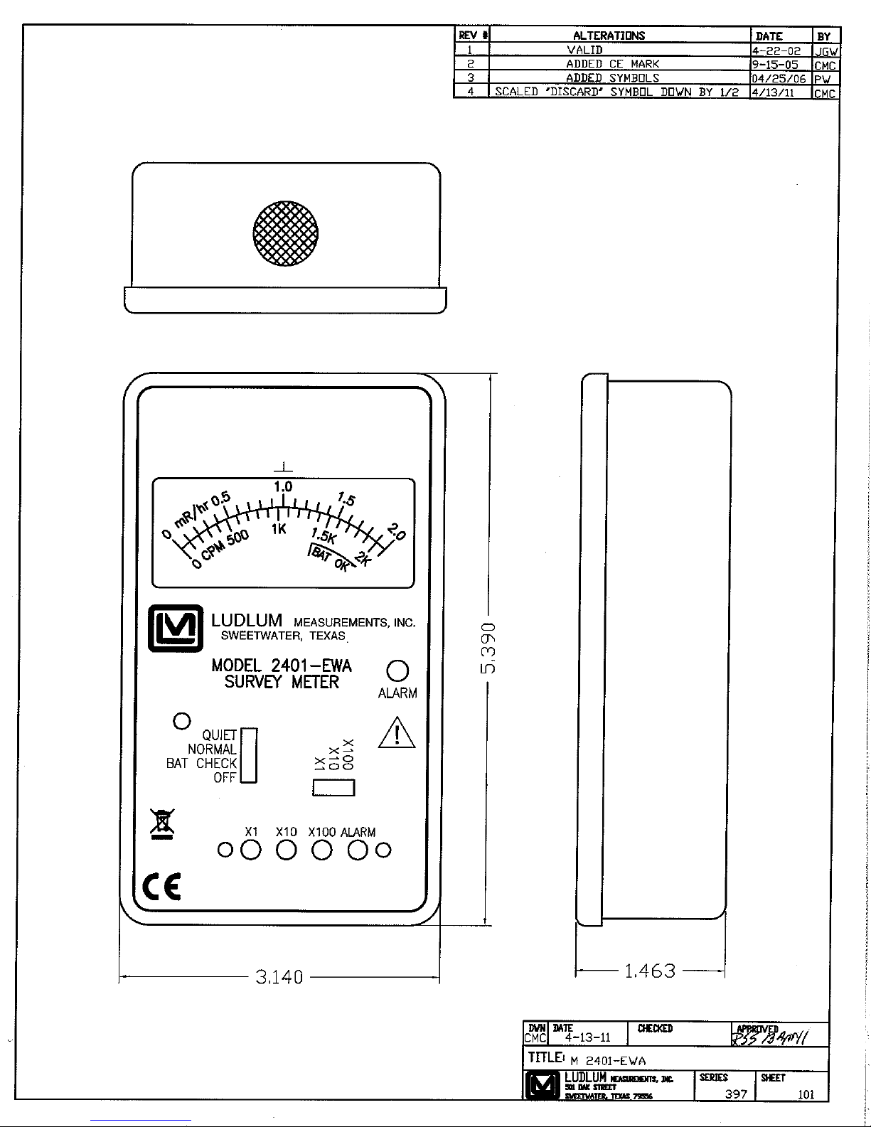
Size: 4.6 x 8.4 x 13.5 cm (1.8 x 3.3 x 5.3 in.) (H x W x L)
Weight: 0.4 kg (0.9 lb), including battery
Finish: drawn-and-cast aluminum fabrication, with beige powder-coat
paint and a recessed subsurface-printed membrane panel
Ludlum Measurements, Inc. Page 3-2 September 2011

MODELS 2401-ECA, 240 1-EWA, 2401-EC2A & 2401-PA Section 4
Section
4
Identification of Controls and
Functions
Meter Face
standard with a mR/hr scale and a BAT OK scale. In addition, most
meter faces have a cpm scale. The actual radiation measurement is
determined by multiplying the meter face reading by the multiple
associated by the selected position of the range switch.
Range Switch: This is a three-position switch marked ×1, ×10, and ×
100. Moving the range switch to one of the range multiplier positions
(×100, ×10, ×1) provides the operator with an overall range dependent
upon the series of instrument and detector used. Multiply the scale
reading by the multiplier to determine the actual scale reading.
Selector Switch: Sliding the range switch from OFF to BAT CHECK
provides the operator with a battery check of the instrument. A BAT OK
scale on the meter face provides a visual means of checking the
battery-charge status. Placing this switch in the NORMAL position puts
the instrument into normal operating mode and energizes the unimorph
speaker located on the left side of the instrument. The number of
audible clicks is relative to the meter reading; the higher the reading, the
more audible clicks. To reduce battery drain, the switch should be placed
in the QUIET position when the audio function is not needed.
: Meter faces vary within the series, though all come
Important!
Units of exposure rate, such as mR/hr, apply to gamma
radiation only . However, exposure rate readings on the Model
2401-EWA or 2401-PA may be affected by alpha and beta
particles if they are not intentionally blocked.
Alarm Set Point Adjustment: This is a recessed potentiometer located
under the front-panel calibration cover used to adjust the alarm set
point. The point is set by placing the instrument in a field of radiation
where the meter reading comes to the desired point of alarm and then
Ludlum Measurements, Inc. Page 4-1 September 2011
adjusting the potentiometer just until the alarm indicators are activated.

MODELS 2401-ECA, 240 1-EWA, 2401-EC2A & 2401-PA Section 4
Alternatively, a Ludlum Model 500 Pulser (or equivalent) may be used to
inject counts, at the detector anode, to the desired meter reading.
Range Calibration Adjustments: These are recessed potentiometers
located under the front-panel calibration cover that allow for individual
calibration of each range multiplier.
Crosshairs: The crosshairs above the meter on the black, front panel
indicate the location of the center of the detector. The exception to this
is in the case of the Model 2401-PA where the center of the detector is
visible on the back side of the instrument. When surveying for radiation,
position the instrument as close as possible to the area to be measured,
with the detector centered.
Ludlum Measurements, Inc. Page 4-2 September 2011

MODELS 2401-ECA, 240 1-EWA, 2401-EC2A & 2401-PA Section 5
Section
5
Safety Considerations and
Maintenance
Environment al Conditions for Normal Use
Indoor or outdoor use
No maximum altitude with the exception of the Model 2401-EWA and
2401-PA where an altitude of 2438 m (8000 ft) above sea level should
not be exceeded. The later two instruments must be sealed in an airtight
container when transported by air in order to prevent damage to the
detector.
Temperature range of -20 to 50°C (-4 to 122°F); may be certified for
operation from -40 to 65 °C (-40 to 150 °F)
Maximum relative humidity of 95% (non-condensing) (Pollution Degree
3 (as defined by IEC 664) (Occurs when conductive pollution or dry
nonconductive pollution becomes conductive due to condensation. This
is typical of industrial or construction sites.)
Warning Markings and Symbols
Caution!
The operator or responsible body is cautioned that the
protection provided by the equipment may be impaired if the
equipment is used in a manner not specified by Ludlum
Measurements, Inc.
The Model 2401 Alarming Series of Instruments
are marked with the following symbols:
CAUTION (per ISO 3864, No. B.3.1) – designates hazardous live voltage
and risk of electric shock. During normal use, internal components are
hazardous live. This instrument must be isolated or disconnected from the
hazardous live voltage before accessing the internal components. This
symbol appears on the front panel. Note the following precautions:
Ludlum Measurements, Inc. Page 5-1 September 2011
MODELS 2401-ECA, 240 1-EWA, 2401-EC2A & 2401-PA Section 5
Warning!
The operator is strongly cautioned to take the following
precautions to avoid contact with internal hazardous live parts
that are accessible using a tool:
1. Turn the instrument power OFF and remove the battery.
2. Allow the instrument to sit for one minute before accessing
internal components.
The “crossed-out wheelie bin” symbol notifies the consumer that the
product is not to be mixed with unsorted municipal waste when discarding;
each material must be separated. The symbol is placed on the front panel.
See section 7, “Recycling,” for further information.
The “CE” mark is used to identify this instrument as being acceptable for
use within the European Union.
Mica Window Precauti on
Caution!
Damage to the Mica window on the top of the Model 2401EWA and on the back of the Model 2401-PA may result if
careful instrument handling is not practiced. The window is
very fragile and may be punctured quite easily.
Cleaning and Maintenance Precautions
Instrument maintenance consists of keeping the instrument clean and
periodically checking the battery, slide switches and calibration. The Model
2401 series of instruments (excluding detector window on Models 2401EWA and 2401-PA) may be cleaned externally with a damp cloth, using only
water as the wetting agent. Do not immerse the instrument in any liquid.
Observe the following precautions when cleaning or performing
maintenance on the instrument:
1. Turn the instrument OFF and remove the battery.
2. Allow the instrument to sit for one minute before cleaning the
exterior or accessing any internal components for maintenance.
Ludlum Measurements, Inc. Page 5-2 September 2011

MODELS 2401-ECA, 240 1-EWA, 2401-EC2A & 2401-PA Section 5
Maintenance
RECALIBRATION
Recalibration should be accomplished after maintenance or adjustments
have been performed on the instrument. Recalibration is not normally
required following instrument cleaning or battery replacement
Note:
Ludlum Measurements, Inc. recommends recalibration at
intervals no greater than one year. Check appropriate local
procedures and regulations to determine required recalibration
intervals.
Ludlum Measurements offers a full-service repair and calibration
department. We not only repair and calibrate our own instruments but most
other manufacturers’ instruments. Calibration procedures are available upon
request for customers who choose to calibrate their own instruments.
SLIDE SWITCHES
Use of the instrument in extremely dusty or dirty environments may cause
the slide switches (instrument selector and range switch) to operate
erratically. These switches may be restored to proper operation by applying
low-pressure air to remove the accumulated dirt.
Ludlum Measurements, Inc. Page 5-3 September 2011

MODELS 2401-ECA, 240 1-EWA, 2401-EC2A & 2401-PA Section 6
Section
6
Radiation Basics
Radiation and Life
Adapted from Eric J. Hall’s book, “Radiation and Life”
Radiation is energy traveling through space. Sunshine is one of the most
familiar forms of radiation. It delivers light, heat, and suntans. We control its
effect on us with sunglasses, shade, air conditioners, hats, clothes, and
sunscreen.
There would be no life on earth without lots of sunlight, but we have
increasingly recognized that too much of it on our bodies is not a good
thing. In fact, it may be dangerous, so we control our exposure to it.
Sunshine consists of radiation in a range of wavelengths from long-wave
infrared to short-wavelength ultraviolet, which creates the hazard.
Beyond ultraviolet are higher energy kinds of radiation, which are used in
medicine and that we all get in low doses from space, from the air, and from
the earth. Collectively we can refer to these kinds of radiation as ionizing
radiation. It can cause damage to matter, particularly living tissue. At high
levels it is, therefore, dangerous, so it is necessary to control our exposure.
Background radiation is that which is naturally and inevitably present in our
environment. Levels of this can vary greatly. People living in granite areas or
on mineralized sands receive more terrestrial radiation than others, while
people living or working at high altitudes receive more cosmic radiation. A
lot of our natural exposure is due to radon, a gas which seeps from the
earth's crust and is present in the air we breathe.
Ludlum Measurements, Inc. Page 6-1 September 2011

MODELS 2401-ECA, 240 1-EWA, 2401-EC2A & 2401-PA Section 6
1 adult human (2.7 X 10⁻⁹ Ci/kg)
1.89 X 10
-7
Ci
1 kg (2.2 lb) of coffee
2.70 X 10⁻⁸ Ci
1 kg (2.2 lb) of super phosphate fertilizer
1.35 X 10⁻⁷ Ci
The air in a 100 m2 (1076 ft2) Australian
The air in many 100 m2 (1076 ft2) European
homes (radon)
1 household smoke detector (with
Radioisotope for medical diagnosis
1.89 X 10⁻³ Ci
Radioisotope source for medical therapy
2702.7 Ci
1 kg (2.2 lb) of 50-year old vitrified highlevel nuclear waste
1 luminous Exit sign (1970s)
27.027 Ci
1 kg (2.2 lb) of uranium
675.68 X 10⁻⁶ Ci
1 kg (2.2 lb) of uranium ore (Canadian, 15%)
675.68 X 10⁻⁶ Ci
The Unstable Atom
Radiation comes from atoms, the basic building blocks of matter.
Most atoms are stable; a carbon-12 atom, for example, remains a carbon-12
atom forever, and an oxygen-16 atom remains an oxygen-16 atom forever,
but certain atoms eventually disintegrate into a totally new atom. These
atoms are said to be “unstable” or radioactive. An unstable atom has excess
internal energy, with the result that the nucleus can undergo a spontaneous
change towards a more stable form. This is called radioactive decay.
When an atom of a radioisotope decays, it gives off some of its excess
energy as radiation in the form of gamma rays or fast-moving, sub-atomic
particles. One can describe the emissions as gamma, beta, and alpha
radiation.
Apart from the normal measures of mass and volume, the amount of
radioactive material is given in curie (Ci), a measure that enables us to
compare the typical radioactivity of some natural and other materials.
Radioactivity of some natural and other materials
home (radon)
americium)
8.12 X 10⁻⁸ Ci
8.12 X 10⁻⁷ Ci
8.12 X 10⁻⁷ Ci
270.27 Ci
Ludlum Measurements, Inc. Page 6-2 September 2011

MODELS 2401-ECA, 240 1-EWA, 2401-EC2A & 2401-PA Section 6
1 kg (2.2 lb) of uranium ore (Australian,
1 kg (2.2 lb) of low-level radioactive waste
27.03 X 10⁻⁶ Ci
1 kg (2.2 lb) of coal ash
5.41 X 10⁻⁸ Ci
1 kg (2.2 lb) of granite
2.70 X 10⁻⁸ Ci
0.3%)
NB. Though the intrinsic radioactivity is the same, the radiation dose received by someone handling a
kilogram of high grade uranium ore will be much greater than for the same exposure to a kilogram of
separated uranium, since the ore contains a number of short-lived decay products (see section on Radioactive
Decay).
13.51 X 10⁻⁶ Ci
Radioactiv e Decay
Atoms in a radioactive substance decay in a random fashion but at a
characteristic rate. The length of time this takes, the number of steps
required, and the kinds of radiation released at each step are well known.
The half-life is the time taken
for half of the atoms of a
radioactive substance to
decay. Half-lives can range
from less than a millionth of a
second to millions of years,
depending upon the element
concerned. After one half-life,
the level of radioactivity of a
substance is halved, after two
half-lives, it is reduced to one
quarter, after three half-lives,
to one-eighth and so on.
more radiation it emits per unit mass. Much of the natural radioactivity in
rocks and soil comes from this decay chain.
Ludlum Measurements, Inc. Page 6-3 September 2011
All uranium atoms are mildly
radioactive. The following
figure for uranium-238 shows
the series of different
radioisotopes it becomes as it
decays, the type of radiation
given off at each step and the
half-life of each step on the
way to stable, non-radioactive
lead-206. The shorter-lived
each kind of radioisotope, the
MODELS 2401-ECA, 240 1-EWA, 2401-EC2A & 2401-PA Section 6
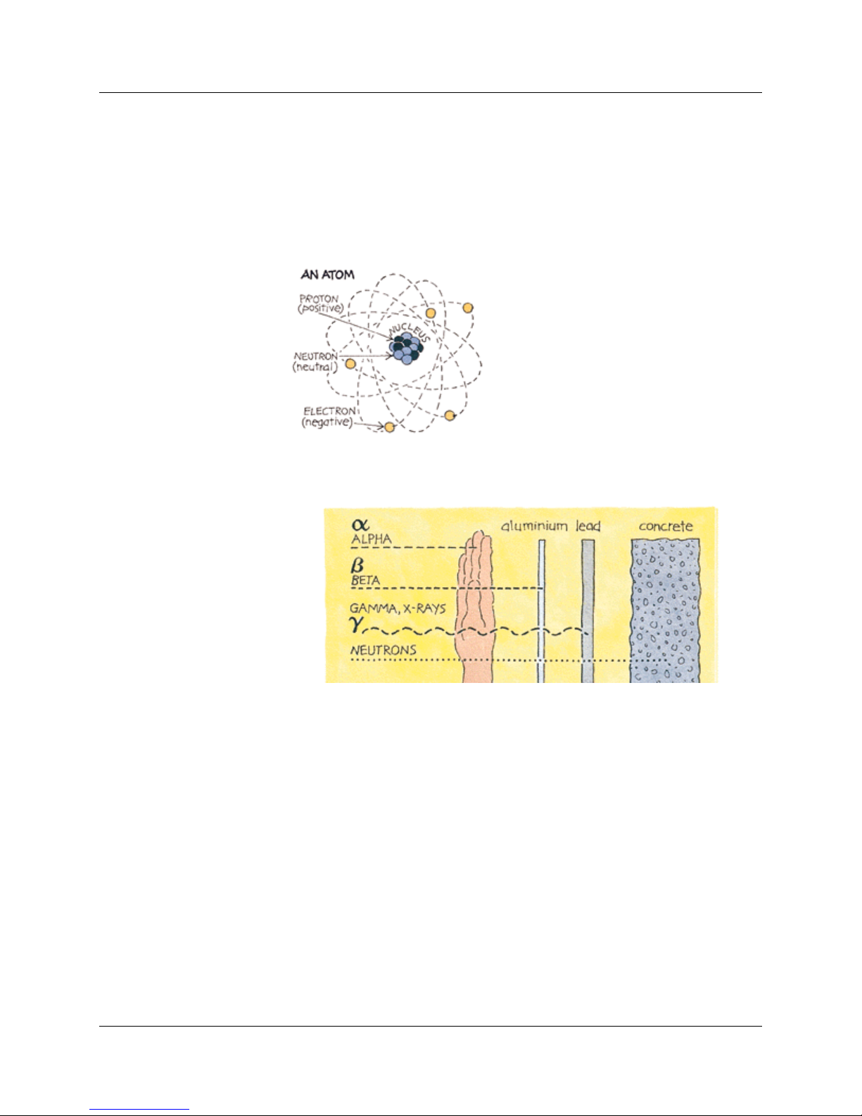
Ionizing Radi ation
Here we are concerned mainly with ionizing radiation from the atomic
nucleus. It occurs in two forms – rays and particles – at the high frequency
end of the energy spectrum.
There are several types of ionizing radiation:
X-rays and gamma rays, like light, represent energy transmitted in a
wave without the movement of material, just as heat and light from a
fire or the sun travel through space. X-rays and gamma rays are virtually
identical, except that X-rays are generally produced artificially rather than
coming from the atomic nucleus. Unlike light, X-rays and gamma rays
have great penetrating power and can pass through the human body.
Thick barriers of concrete, lead, or water are used as protection from
them.
Alpha particles consist of two protons and two neutrons, in the form
of atomic nuclei. They thus have a positive electrical charge and are
emitted from naturally occurring heavy elements such as uranium and
radium, as well as from some man-made elements. Because of
Ludlum Measurements, Inc. Page 6-4 September 2011

MODELS 2401-ECA, 240 1-EWA, 2401-EC2A & 2401-PA Section 6
their relatively large size, alpha particles collide readily with matter and
lose their energy quickly. They, therefore, have little penetrating power
and can be stopped by the first layer of skin or a sheet of paper.
However, if alpha sources are taken into the body, for example by
breathing or swallowing radioactive dust, alpha particles can affect the
body's cells. Inside the body, because they give up their energy over a
relatively short distance, alpha particles can inflict more severe biological
damage than other radiations.
Beta particles are fast-moving electrons ejected from the nuclei of
atoms. These particles are much smaller than alpha particles and can
penetrate up to 0.20 cm (5/64 of an inch) of water or human flesh. Beta
particles are emitted from many radioactive elements. They can be
stopped by a sheet of aluminum a few millimeters thick.
Neutrons are particles that are also very penetrating. On Earth they
mostly come from the splitting, or fissioning, of certain atoms inside a
nuclear reactor. Water and concrete are the most commonly used shields
against neutron radiation from the core of the nuclear reactor.
Note:
It is important to understand that alpha, beta, gamma and Xradiation do not cause the body, or any object around the
source, to become radioactive. However, most materials in
their natural state (including body tissue) contain measurable
amounts of radioactivity.
Measuring Ioniz ing Radia tion
RAD and REM
The human senses cannot detect radiation or discern whether a material is
radioactive. However, a variety of instruments can detect and measure
radiation reliably and accurately.
Ludlum Measurements, Inc. Page 6-5 September 2011

MODELS 2401-ECA, 240 1-EWA, 2401-EC2A & 2401-PA Section 6
The amount of ionizing radiation, or 'dose', received by a person is measured
in terms of the energy absorbed in the body tissue, and is expressed in RAD.
One rad is 0.01 joules deposited per kilogram of mass.
Equal exposure to different types of radiation expressed as RAD, do not
however, necessarily produce equal biological effects. One rad of alpha
radiation, for example, will have a greater effect than one rad of beta
radiation. When we talk about radiation effects, we, therefore, express the
radiation as effective dose in a unit called the REM (Roentgen Equivalent
Man).
Regardless of the type of radiation, one rem of radiation produces the same
biological effect. (100 rem = 1 Sv)
Smaller quantities are expressed in mrem (one thousandth of a rem) or µrem
(one millionth of a rem). We will use the most common unit, rem, here.
What Are The Health Risks F rom Ionizin g
Radiation?
It has been known for many years that large doses of ionizing radiation,
much larger than background levels, can cause a measurable increase in
cancers and leukemias (cancer of the blood) after some years delay. It must
also be assumed, because of experiments on plants and animals, that ionizing
radiation can also cause genetic mutations that affect future generations,
although there has been no evidence of radiation-induced mutation in
humans. At very high levels, radiation can cause sickness and death within
weeks of exposure. (See table on next page.)
But what are the chances of developing cancer from low doses of radiation?
The prevailing assumption is that any dose of radiation, no matter how
small, involves a possibility of risk to human health. However there is no
scientific evidence of risk at doses below approximatly 5 rem in a short
period of time or about 10 rem over a period of one year.
Higher accumulated doses of radiation might produce a cancer that would
only be observed several years (up to 20) after the radiation exposure. This
delay makes it impossible to say with any certainty which of many possible
agents were the cause of a particular cancer. In western countries, about a
quarter of people die from cancers, with smoking, dietary factors, genetic
factors and strong sunlight being among the main causes. Radiation is a
weak carcinogen, but undue exposure could certainly increase health risks.
Ludlum Measurements, Inc. Page 6-6 September 2011

MODELS 2401-ECA, 240 1-EWA, 2401-EC2A & 2401-PA Section 6
1,000 rem as a short-term and whole-body dose would cause immediate
100 rem in a short term dose is about the threshold for causing
Above about 10 rem, the probability of cancer (rather than the severity
incidence of fatal cancer were 25%, this dose would increase it to 30%).
5 rem is, conservatively, the lowest dose at which there is any evidence
local
On the other hand, large doses of radiation directed specifically at a tumor
are used in radiation therapy to kill cancerous cells, and thereby often save
lives (usually in conjunction with chemotherapy or surgery). Much larger
doses are used to kill harmful bacteria in food, and to sterilize bandages and
other medical equipment. Radiation has become a valuable tool in our
modern world.
How Muc h Ionizing Radia tion is Dangerous?
Radiation levels and thei r effects
The following table gives an indication of the likely effects of a range of
whole body radiation doses and dose rates to individuals:
illness, such as nausea and decreased white blood cell count, and
subsequent death within a few weeks.
Between 200 and 1000 rem in a short-term dose would cause severe
radiation sickness with increasing likelihood that this would be fatal.
immediate radiation sickness in a person of average physical attributes,
but would be unlikely to cause death. Above 100 rem, severity of illness
increases with dose.
If doses greater than 100 rem occur over a long period they are less
likely to have early health effects but they create a definite risk that
cancer will develop many years later.
of illness) increases with dose. The estimated risk of fatal cancer is 5 of
every 100 persons exposed to a dose of 100rem (ie. if the normal
of cancer being caused in adults. It is also the highest dose which is
allowed by regulation in any one year of occupational exposure. Dose
rates greater than 5 rem/yr arise from natural background levels in
several parts of the world but do not cause any discernible harm to
populations.
Ludlum Measurements, Inc. Page 6-7 September 2011

MODELS 2401-ECA, 240 1-EWA, 2401-EC2A & 2401-PA Section 6
2 rem/yr averaged over 5 years is the limit for radiological personnel
miners, and hospital workers (who are all closely monitored).
1 rem/yr is the maximum actual dose rate received by any Australian
300-500 mrem/yr is the typical dose rate (above background) received
by uranium miners in Australia and Canada.
300 mrem/yr (approx) is the typical background radiation from natural
from radon in air.
200 mrem/yr (approximately) is the typical background radiation from
30-60 mrem/yr is a typical range of dose rates from artificial sources of
radiation, mostly medical.
5 mrem/yr, a very small fraction of natural background radiation, is the
electricity generating station. In practice, the actual dose is less.
such as employees in the nuclear industry, uranium or mineral sands
uranium miner.
sources in North America, including an average of almost 200 mrem/yr
natural sources, including an average of 70 mrem/yr from radon in air.
This is close to the minimum dose received by all humans anywhere on
Earth.
design target for maximum radiation at the perimeter fence of a nuclear
What is the risk estimate?
According to the Biological Effects of Ionizing Radiation committee V
(BEIR V), the risk of cancer death is 0.08% per rem for doses received
rapidly (acute) and might be two to four times (0.04% per rem) less than that
for doses received over a long period of time (chronic). These risk estimates
are an average for all ages, males and females, and all forms of cancer. There
is a great deal of uncertainty associated with the estimate.
Risk from radiation exposure has been estimated by other scientific groups.
The other estimates are not the exact same as the BEIR V estimates, due to
differing methods of risk and assumptions used in the calculations, but all
are close.
Risk comparison
The real question is: how much will radiation exposure increase my chances
of cancer death over my lifetime.
To answer this, we need to make a few general statements of understanding.
One is that in the US the current death rate from cancer is approximately 20
percent, so out of any group of 10,000 United States citizens, about 2000 of
them will die of cancer. Second, that contracting cancer is a random process,
Ludlum Measurements, Inc. Page 6-8 September 2011

MODELS 2401-ECA, 240 1-EWA, 2401-EC2A & 2401-PA Section 6
Health Risk
Est. life expectancy lost
Smoking 20 cigarettes a day
6 years
Overweight (15%)
2 years
Alcohol (US Avg.)
1 year
All Accidents
207 days
All Natural Hazards
7 days
Occupational dose (300 mrem/yr)
15 days
Occupational dose (1 rem/yr)
51 days
where given a set population, we can estimate that about 20 percent will die
from cancer, but we cannot say which individuals will die. Finally, that a
conservative estimate of risk from low doses of radiation is thought to be
one in which the risk is linear with dose. That is, that the risk increases with a
subsequent increase in dose. Most scientists believe that this is a conservative
model of the risk.
So, now the risk estimates: If you were to take a large population, such as
10,000 people and expose them to one rem (to their whole body), you would
expect approximately eight additional deaths (0.08% X 10,000 X 1 rem). So,
instead of the 2,000 people expected to die from cancer naturally, you would
now have 2,008. This small increase in the expected number of deaths
would not be seen in this group, due to natural fluctuations in the rate of
cancer.
What needs to be remembered is that it is not known that 8 people will die,
but that there is a risk of 8 additional deaths in a group of 10,000 people if
they would all receive 1rem instantaneously.
If they would receive the 1 rem over a long period of time, such as a year,
the risk would be less than half this (<4 expected fatal cancers).
Risks can be looked at in many ways. Here are a few ways to help visualize
risk:
One way often used is to look at the number of "days lost" out of a
population due to early death from separate causes, then dividing those
days lost between the population to get an "Average Life expectancy
lost" due to those causes. The following is a table of life expectancy lost
for several causes:
Ludlum Measurements, Inc. Page 6-9 September 2011

MODELS 2401-ECA, 240 1-EWA, 2401-EC2A & 2401-PA Section 6
Industry Type
Est. life expectancy lost
All Industries
60 days
Agriculture
320 days
Construction
227 days
Mining and quarrying
167 days
Manufacturing
40 days
Occupational dose (300 mrem/yr)
15 days
Occupational dose (1 rem/yr)
51 days
Smoking 1.4 cigarettes (lung cancer)
You can also use the same approach to looking at risks on the job:
These are estimates taken from the NRC Draft guide DG-8012 and were adapted from B.L Cohen and I.S.
Lee, "Catalogue of Risks Extended and Updates", Health Physics, Vol. 61, September 1991.
Another way of looking at risk, is to look at the Relative Risk of 1 in a
million chances of dying of activities common to our society:
Eating 40 tablespoons of peanut butter
Spending 2 days in New York City (air pollution)
Driving 40 miles in a car (accident)
Flying 2500 miles in a jet (accident)
Canoeing for 6 minutes
Receiving 10 mrem of radiation (cancer)
Adapted from DOE Radiation Worker Training, based on work by B.L Cohen, Sc.D.
Background Ra diation
Naturally occurring background radiation is the main source of exposure for
most people. Levels typically range from about 150-350 mrem per year but
can be more than 5rem/yr. The highest known level of background
radiation affecting a substantial population is in Kerala and Madras States in
India where some 140,000 people receive doses that average over 1.5
rem/year from gamma radiation, in addition to a similar dose from radon.
Comparable levels occur in Brazil and Sudan, with average exposures up to
about 4 rem/yr to many people.
Several places are known in Iran, India, and Europe where natural
background radiation gives an annual dose of more than 5 rem and up to
26 rem (at Ramsar in Iran). Lifetime doses from natural radiation range
Ludlum Measurements, Inc. Page 6-10 September 2011

MODELS 2401-ECA, 240 1-EWA, 2401-EC2A & 2401-PA Section 6
up to a couple thousand rem. However, there is no evidence of increased
cancers or other health problems arising from these high natural levels.
Man-made Radiation
Ionizing radiation is also generated in a range of medical, commercial, and
industrial activities. The most familiar and, in national terms, the largest of
these sources of exposure is medical X-rays.
Natural radiation contributes about 88% of the annual dose to the
population and medical procedures contribute most of the remaining 12%.
Natural and artificial radiations are not different in kind or effect.
Protection from Radia tion
Radiation is very easily detected. There is a range of simple, sensitive
instruments capable of detecting minute amounts of radiation from natural
and man-made sources. There are three ways in which people are protected
from identified radiation sources:
Limiting time: For people who are exposed to radiation in addition to
natural background radiation through their work, the dose is reduced
and the risk of illness essentially eliminated by limiting exposure time.
Proper job planning is essential in achieving lowest exposure time.
Always plan for the unexpected to eliminate delays in the exposure area.
Distance: In the same way that heat from a fire is less the further away
you are, so the intensity of radiation decreases with distance from its
source. Distance is the easiest, fastest, and most practical way to limit
exposure.
Shielding: Barriers of lead, concrete, or water give good protection from
penetrating radiation such as gamma rays. Highly radioactive materials
are, therefore, often stored or handled under water, or by remote control
in rooms constructed of thick concrete or lined with lead.
Ludlum Measurements, Inc. Page 6-11 September 2011

MODELS 2401-ECA, 240 1-EWA, 2401-EC2A & 2401-PA Section 6
Standards and R egulation
Much of the evidence that has led to today's standards derives from the
atomic bomb survivors in 1945, which were exposed to high doses incurred
in a very short time. In setting occupational risk estimates, some allowance
has been made for the body's ability to repair damage from small exposures,
but for low-level radiation exposure, the degree of protection may be unduly
conservative.
Most countries have their own systems of radiological protection, which are
often based on the recommendations of the International Commission on
Radiological Protection (ICRP). The “authority” of the ICRP comes from
the scientific standing of its members and the merit of its recommendations.
Who is in charge?
Ultimately, you are. All of the sources of radiation, other than natural, are
regulated by laws passed by Congress. Like any other law, you have your
right to voice your views and opinions about it. The regulations that control
the use of radioactivity in our country are based upon recommendations of
science organizations like the International Commission on Radiological
Protection (ICRP), the National Council on Radiation Protection (NCRP),
the International Atomic Energy Agency (IAEA), the United Nations (UN),
and the Health Physics Society (HPS). Governing bodies like the
Environmental Protection Agency (EPA), the Nuclear Regulatory
Commission (NRC), the Department of Energy (DOE), and the Food and
Drug Administration (FDA) review these recommendations and propose
the regulations that industry and government must follow. These are then
passed by Congress, if found to be acceptable, and published in the Code of
Federal Regulations (CFRs).
Ludlum Measurements, Inc. Page 6-12 September 2011
Note:
The CFR limits the general public to radiation exposure of
100 mrem/year, with no more than 2 mrem of exposure in
any one hour (ref. 10 CFR 20.1301).

MODELS 2401-ECA, 240 1-EWA, 2401-EC2A & 2401-PA Section 7
Section
7
L
Recycling
udlum Measurements, Inc. supports the recycling of the electronics
products it produces for the purpose of protecting the environment
and to comply with all regional, national, and international agencies
that promote economically and environmentally sustainable
recycling systems. To this end, Ludlum Measurements, Inc. strives to supply
the consumer of its goods with information regarding reuse and recycling of
the many different types of materials used in its products. With many
different agencies – public and private – involved in this pursuit it becomes
evident that a myriad of methods can be used in the process of recycling.
Therefore, Ludlum Measurements, Inc. does not suggest one particular
method over another, but simply desires to inform its consumers of the
range of recyclable materials present in its products, so that the user will
have flexibility in following all local and federal laws.
The following types of recyclable materials are present in Ludlum
Measurements, Inc. electronics products, and should be recycled separately.
The list is not all-inclusive, nor does it suggest that all materials are present in
each piece of equipment:
Batteries Glass Aluminum and Stainless Steel
Circuit Boards Plastics Liquid Crystal Display (LCD)
Ludlum Measurements, Inc. products, which have been placed on the
market after August 13, 2005, have been labeled with a symbol recognized
internationally as the “crossed-out wheelie bin. This notifies the consumer
that the product is not to be mixed with unsorted municipal waste when
discarding; each material must be separated. The symbol is placed on the
instrument front panel and appears as such:
Ludlum Measurements, Inc. Page 7-1 September 2011

MODELS 2401-ECA, 240 1-EWA, 2401-EC2A & 2401-PA Section 8
Section
8
CAPACITORS
TRANSISTORS
Models 2401-ECA,
2401-EWA and 2401EC2A Survey Meters
Main Board,
Drawing 397 × 87
Parts List
Reference Description
UNIT Completely Assembled
Survey Meter:
Model 2401-ECA 48-2996
Model 2401-EWA 48-2997
Model 2401-EC2A 48-2995
BOARD Completely Assembled
Main Circuit Board 5397-085
C001 68µF, 6.3V 04-5654
C021 470PF, 100V 04-5668
C031-C039 470PF, 1KV 04-5693
C041 470PF, 1KV 04-5693
C101 10µF, 20V 04-5655
C102 0.0015µF, 100V 04-5680
C111 0.1µF, 50V 04-5663
C131-C132 47PF, 100V 04-5660
C211 10µF, 20V 04-5655
C231 0.022µF, 50V 04-5667
C232 27PF, 100V 04-5658
C233 100PF, 100V 04-5661
C0310 470PF, 1KV 04-5693
C0311 10µF, 20V 04-5655
C0312 27PF, 100V 04-5658
Q021 2N7002L 05-5840
Q031 MTD2N50 05-5855
Q131 MMBT3904T 05-5841
Q221 2N7002L 05-5840
Part Number
Ludlum Measurements, Inc. Page 8-1 September 2011

MODELS 2401-ECA, 240 1-EWA, 2401-EC2A & 2401-PA Section 8
INTEGRATED
LED
DIODES
THERMISTOR
SWITCHES
POTENTIOMETERS
RESISTORS
CIRCUITS
Reference Description
Part Number
U021 ICM7555CBA 06-6300
U101 MAX638AESA 06-6389
U131 MAX641BCSA 06-6388
U211 CA3096M 06-6288
U212 TLC27M7ID 06-6292
U221 CD74HC4066M 06-6323
U231 CD74HC4538M 06-6297
DS121 ALARM, HLMP4700 07-6356
CR001 CXSH-4 07-6358
CR011 CXSH-4 07-6358
CR031-CR034 CMPD2004S 07-6402
CR041 CMPD2004S 07-6402
R214 250 07-6366
S111 OFF-ON-BAT-QUIET 08-6764
S112 RANGE 08-6763
R101 1M, ×1 ADJ 09-6911
R105 1M, ×10 ADJ 09-6911
R107 100K, ×100 ADJ 09-6930
R201 100K, ALARM ADJ. 09-6930
R001 475K, 125mW, 1% 12-7859
R002 165K, 125mW, 1% 12-7877
R021 475K, 125mW, 1% 12-7859
R022 1.00K, 125mW, 1% 12-7832
R031 1.00M, 125mW, 1% 12-7844
R032 3.32M, 125mW, 1% 12-7967
R033 1.00M, 125mW, 1% 12-7844
R034 392K, 125mW, 1% 12-7841
R035-R036 1.00M, 125mW, 1% 12-7844
R102 10.0K, 125mW, 1% 12-7839
R103 100K, 125mW, 1% 12-7834
R111 100K, 125mW, 1% 12-7834
R104 10.0K, 125mW, 1% 12-7839
R106 1.00K, 125mW, 1% 12-7832
R111-R112 100K, 125mW, 1% 12-7834
R113 665K, 125mW, 1% 12-7977
R121 1G 12-7686
Ludlum Measurements, Inc. Page 8-2 September 2011

MODELS 2401-ECA, 240 1-EWA, 2401-EC2A & 2401-PA Section 8
INDUCTORS
MISCELLANEOUS
MISCELLANEOUS
ASSEMBLY
COMPONENTS
Reference Description
Part Number
R131-R132 100K, 125mW, 1% 12-7834
R133 10.0K, 125mW, 1% 12-7839
R202 100K, 125mW, 1% 12-7834
R211 1.00K, 125mW, 1% 12-7832
R212 33.2K, 250mW, 1% 12-7842
R213 301, 125mW, 1% 12-7863
R215 475K, 125mW, 1% 12-7859
R221-R222 1.00M, 125mW, 1% 12-7844
R223 33.2K, 250mW, 1% 12-7842
R224 1.00M, 125mW, 1% 12-7844
R231 100K, 125mW, 1% 12-7834
R232 1.00M, 125mW, 1% 12-7844
R233 100K, 125mW, 1% 12-7834
L001 150µHY 21-9677
L021 220µHY 21-9678
L131 470µHY 21-9699
P1 CONNECTOR-640456-2
MTA100×2, METER 13-8073
DS11 UNIMORPH 21-9782
B121 BATTERY HOLDER 22-9404
* GM TUBE:
Model 2401-ECA: LND71210 01-5295
Model 2401-EWA: LND712 01-5032
Model 2401-EC2A: LND71412 01-5306
* FP & METER ASSY.:
Model 2401-EWA 4397-068
Model 2401-ECA 4397-069
Model 2401-EC2A 4397-070
* Battery, Alkaline, 9V 21-9282
1 ea. MODEL 2401 COVER GASKET 7397-183
* CAN ×10:
Model 2401-EWA 7397-053
Model 2401-ECA/EC2A 7397-052
1 ea. Unimorph Gasket 7397-063
2 ea. Switch Slot Cover 7397-060
1 ea. MODEL 2401 CAL COVER 9397-035
Ludlum Measurements, Inc. Page 8-3 September 2011

MODELS 2401-ECA, 240 1-EWA, 2401-EC2A & 2401-PA Section 8
CAPACITORS
TRANSISTORS
INTEGRATED
DIODES
Model 2401-PA
Survey Meter
Main Board,
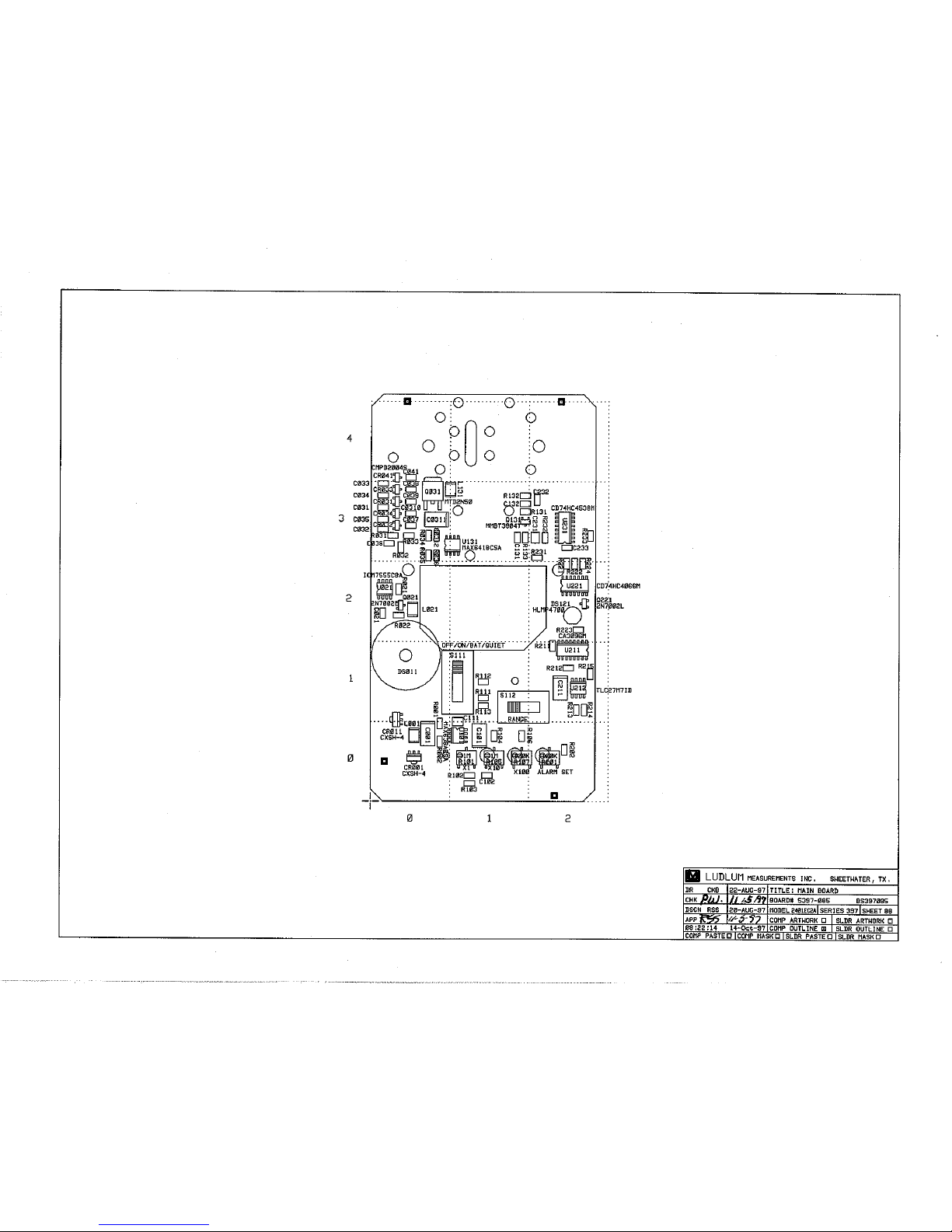
Drawing 397 × 190
CIRCUITS
Reference Description
Part Number
UNIT Completely Assembled Model
2401-PA Survey Meter 48-3400
BOARD Assembled Model 2401-PA
Main Circuit Board 5397-190
C001 68µF, 6.3V 04-5654
C021 470PF, 100V 04-5668
C031-C039 470PF, 1KV 04-5693
C041 470PF, 1KV 04-5693
C101 10µF, 20V 04-5655
C102 0.0015µF, 100V 04-5680
C111 0.1µF, 50V 04-5663
C131 47PF, 100V 04-5660
C132 47PF, 100V 04-5660
C211 10µF, 20V 04-5655
C231 0.022µF, 50V 04-5667
C232 27PF, 100V 04-5658
C233 100PF, 100V 04-5661
C0310 470PF, 100V 04-5693
C0311 10µF, 20V 04-5655
C0312 27PF, 100V 04-5658
Q021 2N7002L 05-5840
Q031 MTD2N50 05-5855
Q131 MMBT3904T 05-5841
Q221 2N7002L 05-5840
U021 ICM7555CBA 06-6300
U101 MAX638AESA 06-6389
U131 MAX641BCSA 06-6388
U211 CA9036M 06-6288
U212 TLC27M7ID 06-6292
U221 CD74HC4066M 06-6323
U231 CD74HC4538M 06-6297
DS121 LED1, HLMP4700 07-6356
CR001 CXSH-4 07-6358
CR011 CXSH-4 07-6358
CR31- CR34 CMPD2004S 07-6402
CR41 CMPD2004S 07-6402
CR101 CXSH-4 EB33 07-6358
Ludlum Measurements, Inc. Page 8-4 September 2011

MODELS 2401-ECA, 240 1-EWA, 2401-EC2A & 2401-PA Section 8
THERMISTOR
SWITCHES
POTENTIOMETERS
RESISTORS
Reference Description
R216 250 07-6366
S111 OFF-ON-BAT-QUIET 08-6764
S112 RANGE 08-6763
R101 1.00M, ×1 ADJ 09-6911
R105 1.00M, ×10 ADJ 09-6911
R107 100K, ×100 ADJ 09-6930
R201 100K, ALARM ADJ 09-6930
R001 475K, 125mW, 1% 12-7859
R002 165K, 125mW, 1% 12-7877
R021 475K, 125mW, 1% 12-7859
R022 1.00K, 125mW, 1% 12-7832
R031 1.00M, 125mW, 1% 12-7844
R032 3.32M, 125mW, 1% 12-7967
R033 1.00M, 125mW, 1% 12-7844
R034 392K, 125mW, 1% 12-7841
R035-R036 1.00M, 125mW, 1% 12-7844
R102 10.0K, 125mW, 1% 12-7839
R103 100K, 125mW, 1% 12-7834
R104 10.0K, 125mW, 1% 12-7839
R106 1.00K, 125mW, 1% 12-7832
R111-R112 100K, 125mW, 1% 12-7834
R113 665K, 250mW, 1% 12-7977
R121 1G 12-7686
R131-R132 100K, 125mW, 1% 12-7834
R133 10.0K, 125mW, 1% 12-7839
R202 100K, 125mW, 1% 12-7834
R211 1.00K, 125mW, 1% 12-7832
R212 33.2K, 125mW, 1% 12-7842
R213 301, 125mW, 1% 12-7863
R215 75K, 125mW, 1% 12-7859
R221- R222 1.00M 125mW, 1% 12-7844
R223 33.2K, 125mW, 1% 12-7842
R224 1.00M, 125mW, 1% 12-7844
R231 100K, 125mW, 1% 12-7834
R232 1.00M, 125mW, 1% 12-7844
R233 100K, 125mW, 1% 12-7834
Part Number
Ludlum Measurements, Inc. Page 8-5 September 2011

MODELS 2401-ECA, 240 1-EWA, 2401-EC2A & 2401-PA Section 8
INDUCTORS
MISCELLANEOUS
MISCELLANEOUS
ASSEMBLY
COMPONENTS
Reference Description
Part Number
L001 150µHY 21-9677
L021 220µHY 21-9678
L131 470µHY 21-9699
P1 CONNECTOR 640456-2,
MTA100×2, METER 13-8073
B122 BATTERY-HLDR #1294
9V PCB 22-9404
DS011 UNIMORPH-PKM22EPP-4001 21-9782
* GM TUBE - LND7311 01-5008
* Tube Clip 01-5237
* MODEL 2401-PA FP & METER ASSY.
4397-188
* Battery, alkaline, 9V 21-9282
1ea. Unimorph Gasket 7397-063
2ea. Switch Slot Cover 7397-060
* MODEL 2401-P CAN 7397-038
* MODEL 2401-P PANCAKE SCREEN
7397-042
* MODEL 2401-P TUBE
HOLDER GASKET 7397-065
* TUBE HOLDER
BOTTOM BRACKET 7397-083
* TUBE HOLDER
TOP BRACKET 7397-084
* MODEL 2401 CAL COVER 9397-035
Ludlum Measurements, Inc. Page 8-6 September 2011

MODELS 2401-ECA, 240 1-EWA, 2401-EC2A & 2401-PA Section 9
Section
9
Drawings
Model 2401-ECA Front View, Drawing 397 × 100
Model 2401-EWA Front View, Drawing 397 × 101
Model 2401-EC2A Front View, Drawing 397 × 99
Model 2401-PA Front View, Drawing 397 × 188
Main Circuit Board Schematic, Drawing 397 × 87
Main Circuit Board Component Layout, Drawing 397 × 88 (2 sheets)
Main Circuit Board Schematic, Drawing 397 × 190
Main Circuit Board Component Layout, Drawing 397 × 191
Ludlum Measurements, Inc. Page 9-1 September 2011


 Loading...