

Page 1
Ludlum Model 2350
DATA LOGGER
Revised: July 1993
Serial No. 106622 and Succeeding
Serial Numbers
Software Version # 37102n16
.
I!!!
cl
LUDLUM
501
OAK ST., P.O.
svuEmTER,Tx78558
9l-FAx:9lW3!%672
MEASUREMENB,
60X
INC.
810
Page 2
f
1
WAND
71.1
I’
15.3
18: 44 DET#O2
uR/hr
0
60 SEC
UR
218 MIN DOS
#OO
0 *o
RAT
’
Et
DOS
1
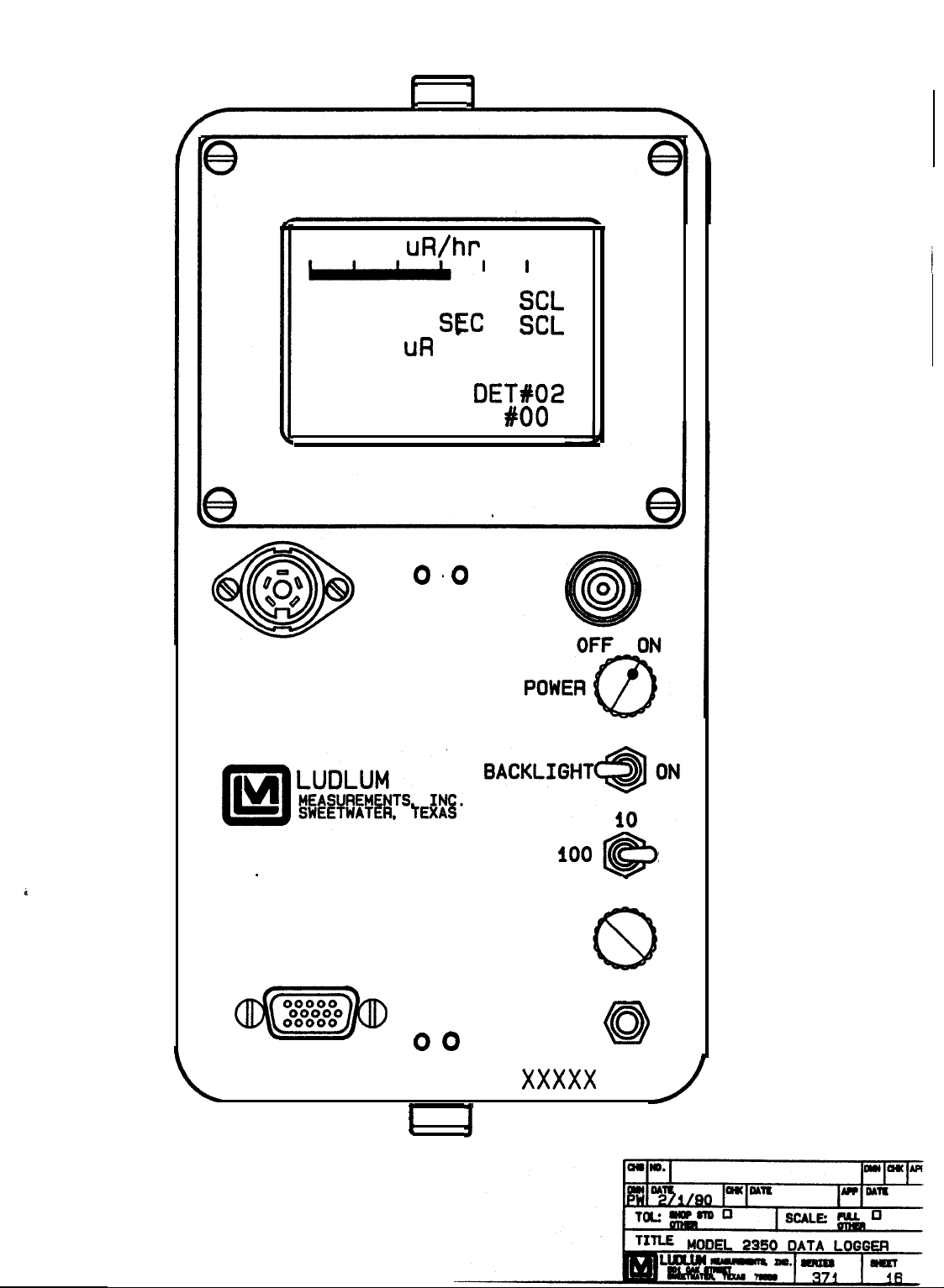
MODEL 2350
DATA LOGGER
SERIAL I/O
(/@zqJ)
o o
I
AUDIO
DIVIDE
ACKNLDGE
1oo
VOLUME
xxxxx
J
1
@
Page 3

Ludlum
of defects due to workmanship, materials, and design for a period of twelve months from the date
of delivery, with the exception of photomultiplier tubes and geiger tubes, which are warranted
ike
for 90 days.
misuse,
In the event of instrument failure, notify Ludlum Measurements, Inc. for repair or replacement.
Liability of this warranty is limited to the purchase price of the insWment.
Be sure to verify that the shipping carton is received in good condition with no visible damage,
Should the instrument be received in a damaged condition, save the shipping container and the
packing material and request an immediate inspection by the carrier.
If equipment needs to be returned to Ludlum Measurements, Inc. for repair or calibration, please
send to the address below. All shipments should include documentation containing return shipping
address, customer name, telephone number, description of service requested, and all other necessary
information. Your
Measurements,
This warranty is voided in instances of improper installation abuse, mishandling,
fkight
damage, or repair by unqualified persons.
uqXration
Inc.
warmnts the,products
RECEMNG CONDITION EXAMINATION
RETURNOFGOOIISToMANuFAcllJRER
will expedite the return of your equipment.
covered in this instruction manual to be
thee
d&ct-
’
:
5olOAKS~
SWEEIWA’IE& TX 79556
91~23~5494
FAX
915-235-4672
Page 4

M2350 Data Logger
1. GENERAL . . . . . . . . . . . . . . . . . . . . . . . . . . . . . . . . . . . . . . . . . . . . . . . . . . . .
2. SPECIFICATIONS . . . . . . . . . . . . . . . . . . . . . . . . . . . . . . . . . . . . . . . . . . . . . . .
3. DESCRIPTION OF FRONT PANEL CONTROLS . . . . . . . . . . . . . . . . . . . . . . . . .
4. DESCRIPTION OF FUNCTIONS . . . . . . . . . . . . . . . .
l
. . . . . . . . . . . . . . . . . . . .
5. OPERATINGPROCEDURES . . . . . . . . . . . . . . . . . . . . . . . . . . . . . . . . . . . . . . .
5.1Installingbatteries.. ...........................................
5.2operatingtheinstrurnent
........................................
5.3P~orminga”coldstart” ........................................
6. DESCRIPTION OF DISPLAY MODES . . . . . . . . . . . . . . . . . . . . . . . . . . . . . . . .
6.1 Normal display . . . . . . . . . . . . . . . . . . . . . . . . . . . . . . . . . . . . . . . . . . . . . . .
6.2ParameWs-d&play..
6.3Detectordisplay
...........................................
..............................................
6.4Alarmdisplay.. ...............................................
6.5Loggeddatadisplay ............................................
6.6Recycledatadisplay
6‘7
Recycle setup display
...........................................
........................................... 9
1
1
2
2
5
5
5
5
6
6
6
7
7
8
8
7. DESCRIPTION OF COMMANDS . . . . . . . . . . . . . . . . . . . . . . . . . . . . . . . . . . .
7.1setcommands
7.2control~~
7.3Readcommands
8.
COMMANDUSAGE
8.1
Scanthrou~thedisplaymodes
8.2Setvariousdetectorsettings
8.3Readvariousdetectorsettings
9. APPLICATIONS
9.1 General M2350 setup
9.2CountratemeterwithaNaIscintillator
9.3Micro-RmeterwithaNaIscintillator..
9.4SurveymeterwithaG-Mdetector..
9.5Lqgingreadhgswithmultipleprobes
9.6Viewloggedreadings
...............................................
............................................
.............................................
............................................
..................................
......................................
.......
..................
j..
..........................
.
..................
.
.........
..........................................
.............................
.............................
...............................
..............................
..........................................
10
11
12
14
18
19
20
21
22
22
22
24
26
27
31
page i
Page 5
10.
SPECIAL,
OPEBA’I’@G MODES _ .i:t, . . . . . . . . . . . . . . . . . . . . . . . . . . . . . . .
34
10.1 Recyclemade
10.2 Dead time calibration
IO;3
CMibration constant
11.
12.
PAR’TSL,IST
EIANDHEL,DTERMINALOPERATION
11.1Terminalsetup
11.2TerminaIoperatibn;.
OPTICALWANDOPERATION..
12.1
Optidtiuse
12.2Barcode generation . . . . . . . . . . . . . . . . . . . . . . . . . . . . . . . . . . . . . . . . . .
. . . . . . . . . . . . . . . ..A.....................~
Model235ODataLogger . . . . . . . . . . . . . . . . . . . . . . . . . . . . . . . . . . . . . . . . . . . .
celltral~Board,~g371x1
Am@PowrsupplyBoard,~~g371x2
Back@w~Dr&ng371
I/Oh~~I>rawving371
WkingDiagfmqIhwing371x4
. .
...............................................
.........................................
..........................................
...........................
...........
........;.........
. . . . . . . . . . . . . . . . . . . . . . . . . . . . . . . . . . . . . . . . . . . .
t...:Y; .:.
.....
x3 . . . . . . . . . . . . . . . . . .;‘. . . . . . . , . . . . .I 48
x5
. . . . . . . . . . . . . . . . . . . . . . . . .
...........................
.......................
.:
,*’
;;.
;......;
I’.
.
.......
. . .
‘;‘.......
.
.....
. . . . . . . . . . . . . . . . . . . . ...*...
. . . . . . . . l . . . . . . ...’ . . . . . . . .
. . . . .
.
.....
.;.
. . . . . . . . . .
.-.;
. . .
.‘.
. . . . .
..
34
36
38
41
41
41
42
42
42
43
43
43
45
48
50
,i
PageJi ,.
.
Page 6
M2350 Data Logger
1.
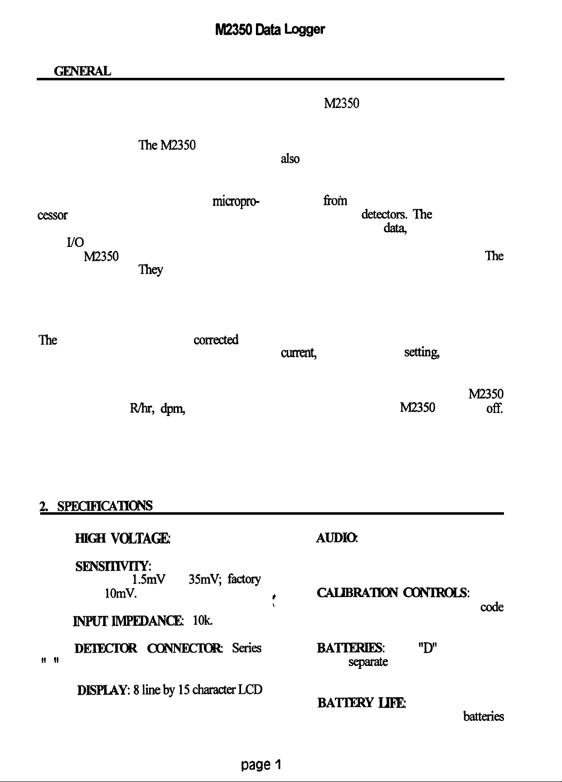
GENmAJJ
The Ludlum Model 2350 Data Logger is
a self contained counting instrument designed
for operation with scintillation, proportional,
or G-M detectors.
The M2350
is complete
with a voltage-sensitive amplifier, single
channel analyzer, detector high voltage power
supply, detector overload sensing circuitry,
and data logging memory all under micropro
cessor control. The settings can be changed
through the bar code reader or the RS-232
serial
I/o
port.
‘The M2350 provides four different types
of data readout.
‘Ihey
are 1) a digital
ratemeter, 2) a five decade. log bar graph
ratemeter, 3) a timed counter, and 4) an
integrated dose counter and timer. All four
readouts operate from the same count input.
The
count displays can be cone&d for
detector dead time.
The digital ratemeter and integrated dose
counter can also have a calibration constant
applied to them to allow direct readout in user
selected units (ie. R/hr,
dpm
cps, etc.). All
readout displays can be individually turned on
or off except for the bar graph display, which
is always displayed. The counters will
continue to function even when the counter
display is turned off.
audio output with a programmable AUDIO
DIVIDE selector switch to increase its
usefulness with sensitive detectors. There is
also a five decade analog output available on
the backplane.
readings
sixteen different detectors. The logged reading
contains the count
detector number, location code, sample
number, status, time, and type of reading.
detector setup memory contains the settings
for the detector calibration constant, detector
dead time, detector high voltage, detector
model number, detector serial number, display
range multiplier, display time base, display
units, integrated dose alarm setting, overload
current,
setting, scaler count time, threshold, and
window.
batteries even when the M2350 is turned
In addition, there is a backup capacitor that
keeps the memory powered for about thirty
minutes when the batteries are removed to
allow time to replace weak batteries.
The
M2350
provides a click per event
The data logging memory can store the
fi-oin
250 samples and the setups for
da&
count time, date,
‘Ihe
ratemeter alarm
&tin&
scaler alarm
The memory is powered by the M2350
off.
l
HEH
. SmsrxlWIYz
adjustable from
calibrated to
l
INPUTIMPEDANCE 1Ok
l Dl!XlEKR
II 11
C.
l DISPUW8lineby15chamcterLCD
WJLTAGEz
With threshold at 100,
1.5mV
1OmV.
cKBNEKR
0
to 2500 volts.
to
35mV,
display with EL backlight.
f&ory
Zkries
paw 1
l
AUDIa
Click per event through built
in unimorph speaker with adjustable volume
and selectable divide by 1, 10, or 100.
l
*
’
all calibrations done through the bar
CAUBMTION
CZCINMU:
None;
code
input or RS-232 serial I/O.
l
BA’lJERIE
batteries in
separate
Four
“D”
cell flashlight
externally accessible
compartment.
l
BATJJRY HFE
hours with Duracell MN1300
From 50 hours to 90
batteries
Page 7
M2350
Data Logger
dependiig upon use of EL backlight. 4.4
volts is considered the end point of the battery
“D”
life. When the batteries reach this point’ there
is about two to four hours use left.
enamel with black silk-screened nomenclature.
.
SIZE 1 lcm (4.25”) W x 22cm (8.75”)
L x
15~x11
(6”) H
(21~x1 (8.25”)H
with
handle).
3.
DESQUETIONOFFlRONTPAN]E3L~
l
DISPIAYz
backlit liquid crystal
l
DFLEcI[1DR: seiies “C”
8 line by 15 character
display.
connector for
detector.
0 Impedance:
o Ballast resistor:
l
F0WERz Twoposition switch to turn
1ok.
1M
used to adjust the vohune of the speaker.
to acknowledge and silence the alarms.
power to instrument on or off.
l
BACKLZGHF
Turns LCD backlight
used to read “3 of 9” code bar codes.
on or off.
l AUDIO DIVIDE Three-position
signals to interface to computers or ternGnals.
switch used to control audio divide by:
l
WEIGHR 2.3 kg (Sibs) including four
cells.
l
FINISH Computer beige polyurethane
o
1: Provides 1 click per event
.
o 10: Provides 1 click per 10 events
o
100: Provides 1 click per 100
events
l
VOUTME:
l
ACKNUKEz
l WAND: Connector for optical wand
l SERIAL
One-turn potentiometer
Pushbutton switch used
IlO:
Connector for RS-232
4. DEERFIlOl’T OF
l
cJlxmmm:
available.
They
all use the same input but
FuNcIIc)INS
l-here are four counters
provide different types of readouts.
0 Digital Ratemeter:
Provides a
digital readout of the detector count rate.
‘Ibis readout is corrected for detector dead
timeandcanalsobecalibmtedfordirect
readout in the desii units and timebase.
o
BarGraph-:
Provides a
five-decade log readout of the detector
count rate in counts per second Tom one
cps to 100 kcps that is
corrected
for
detector dead time.
page
o
Scaler: Providesatimedcounter
for accumulating the detector counts far a
preset time. The count range is up to
999,999 counts with count times
second to 65,535 seconds in one-second
r
increments.
0 Integrated
Dose:
readout of the total accunmlated dose and
the accumulation time in minutes. This
readout is also corrected for detector dead
time and displays in the same units as the
digital ratemeter.
2
f.?om
1
Provides a
Page 8

M2350
Data
Log&r
l CIDCKTheM2350hasarealtime
clock that keeps the time (24hour format) and
programmable up to 2500 volts in one-volt
increments.
date.
l
USER
cation code that can be used to identity each
instrument. The characters can be numbers or
letters.
l
DEIKI0R
sixteen different detector setups can be loaded
into the M2350. Once the setups are loaded a
single
co-d
ID: A fifteen-character identifi-
SELKIlaS:
Up to
is all that is required to
function allows the detector settings to include
the model number of the detector. The model
can be up to nine
include both numbers and letters.
function allows the detector serial number to
be saved so there will be a record of which
detector took which data.
change setups to a different detector. The
following items are stored for each detector
setup:
The digital ratemeter can be programmed to
auto-range or be forced into using a multiplier
of micro,
o Detector calibration constant
0 Detectordeadtime
0
Detector high voltage
0 Detector model number
0 Detectorserialnumber
except
ratemeter can have a time base of seconds,
mini,
0 Display range multiplier
o Display time base
0 Display units
o
Integrated
dose alarm setting
0 overload current
0 Ratemeter alarm setting
0 scaler alarm setting
0
Scaler count time
ratemgrammed
oad, @MY9 NW9 (W, 09, -mg),
@)isintegratioion, (C)aunts, (Ci/cn?),
wcti.
o Threshold
o Window
almns for the digital
integrated dose. When a level is equal to or
l DETECTOR CALIBRATION
CXWSTANT
me digital ratemeter and
integrated dose can be calibrated to read
directly in the desired units. This is
accomplished by dividing the dead
t$ne
corrected ratemeter or integrated dose by the
calibration constant.
exceeds the alarm
turned on and a status message is displayed in
the appropriate display line. The audio output
can be turned off by pressing the
NLDGE button
continue to display the alarm message until
the alarm condition is no longer present.
l DEIlZIORMODElLNUMB~This
characters
l
DEIKTORSEEUALNUMB~UMBER:s
.
DJSPLAY
milli,
l
DISPLAY
Ci/d
or
l DISPLAY
RANGE
none, or kilo.
TIME
and
hours.
UNlTS: The
and integrated dose can be
long and can
MMlXIPLWt
BASE:
For all units
E%q/cn?, the
digital
digital
$ro-
to readout in the following units:
or
l
ALf!RMS:
There are programmable
ratemeter,
setting
the audio output is
scaler, and
ACK-
‘Ihe
status message will
l DETEcroR DEAD
M2350 allows for the correction of dead time
1OsseS.
‘Ills The
detect when the detector is drawing excessive
current and the output
not be accurate. It is programmable up to 40.0
l
DEIlXXX
HIM
VOLTAGE:
Supplies the bias voltage to the detector. It is
p4 in 0.1
disabled if desired.
page 3
l
OlvBImD
/LA
increments. It also can be
CURRENTP.
fi-om
the detector may
used to
Page 9

l
0-W
M23!50
If the count rate is
Data Logger
high enough for 75% dead time conection, the
digital ratemeter will display the message
‘OVER RANGE!’
.
sm
alum
mm
This
provides the preset time the scaler counts. It
can be set from 1 to 65,535 seconds in
one-second increments.
.
sINGLJ3m
ANALYzEFt
The SCA can be disabled to allow for gross
counting or enabled to allow energy discrimination. Both the threshold and window are
rrosle
up to 1000 in integer
.
l
LQGGlNG MEMORY:
samples may be stored
inthe
Up to 250
internal logging
memory and be retrieved later. The following
data is saved:
0
Count data: This is the value of the
counter that was logged. The counter is
either the digital ratemeter, scaler, or
integrated dose.
0
Count time: This is the count time
of the reading. For the digital ratemeter, it
is 0. For the scaler, it is the number of
allows the readout of a specified data sample
without requiring the complete memory to be
dumped.
seconds the scalar counted for. For the
integrated dose, it is the number of
minutesthattheintegrateddosehasbeen
accumulating.
mode where automated logging can-be
pe~%ornxd
f?om
0
Date: The date is stored as month,
day, yf=*
of the 6 logging cycles can be setup to log the
digital
and then wait from 1 to 65,535 seconds before
0 Detector
number:
This is the
number of the detector (from 0 to 15)
whose settings were loaded into the data
loggeratthetimethereadingwastaken.
karting the next logging
mode can be programmed to continue until the
data logger memory is full or for a set number
of recycles.
0
Location code: This is the location
code the user enters. It can be up to ten
characks
long and can be a combination
of numbers and letters. The location code
does not need to be unique for each
readiig since the sample number is
unique.
1
0 Sample number: This is the unique
sample number of the logged reading and
will be
fkom
0 to 249.
0
Status: This records the
IV2350
status at the time of the reading. It contains the alarm,
ov&ad,
and over-range
conditions.
0
Time: The time is stored as
hours,minutes
and is in the 24 hour
format.
0
Logging mode:
Ibis
is the
identifier that records the type of reading
whether it was the digital ratemeter,
scaler, or integrated dose.
l luxx;ED DATA
l
RECYCIE The M2350
DISPLAYz This
has a
recvcle
The recycle cycle can consist of
1 to 6 logging cycles per recycle. Each
rakmekr,
scaler, or integrated dose
cycle.
The recycle
page
4
Page 10

lM23!50
5.OPER4'IlNGl'RCXXDuREs
Data Logger
5Mnstallingbatteries
To install the batteries,unscrewthebattery
door latch and insert four
“D”
cell batteries in
the battery compartment. The correct position
of the batteries is marked on the bat&y door.
Refasten battery door.
5.2Ope1atingtheimtn1ment
Switch the
power ON/OFF
switch to the ON
position. The
display should
turn all blue afkr
about one second.
The blue will
remain on for two
$llle
seconds and then self
be replaced with
the display in Figure 1. After two seconds, the
display will then be replaced with the last
display that was active before the power was
turned off. If the display appeam abnormal, a
cold start needs to be done.
After the power up cycle is completed,
select the desired diilay mode and the
desired detector parameters and proceed with
the
instmmnt
operation.
37102N16
MEMORY TEST OK
CJ?UTESTOK
1.
check.
M235O's
removed long enough for the memory to be
lost or if the user desires to reset the memory
before setting up for specific detectom.
the hand held knninal or
The display should turn all blue afler about
one second The blue display will remain on
for two seconds and then be replaced with the
display in Figure 2.
This will be dis-
played for two
seconds and then
‘the
resume operation
with all settings
set to their default
Values.
*
,
5.3
Performing a ‘kold statt”
NOTE
A cold start wil clear all detectors
P
and also clear the logging memory.
OncedoneJhedata~be
recoVered.
A cold start is needed to clear the
memory if the batteries have been
To do a cold start, enter
IV2350
will
MEMORY TEST OK
SSRwith
the
optical wand
mu TEST
either
OK
COLDINITIALJZE
Cold
Start
Execute.
Page 11
MZ350 Data Logger
6. DESCFUPIlm OFDISPLAY MODES
There are seven different display modes.
‘Ihey are described below.
displayed here. The ‘SCL’ message is always
on and indicates that this is the scaler timer.
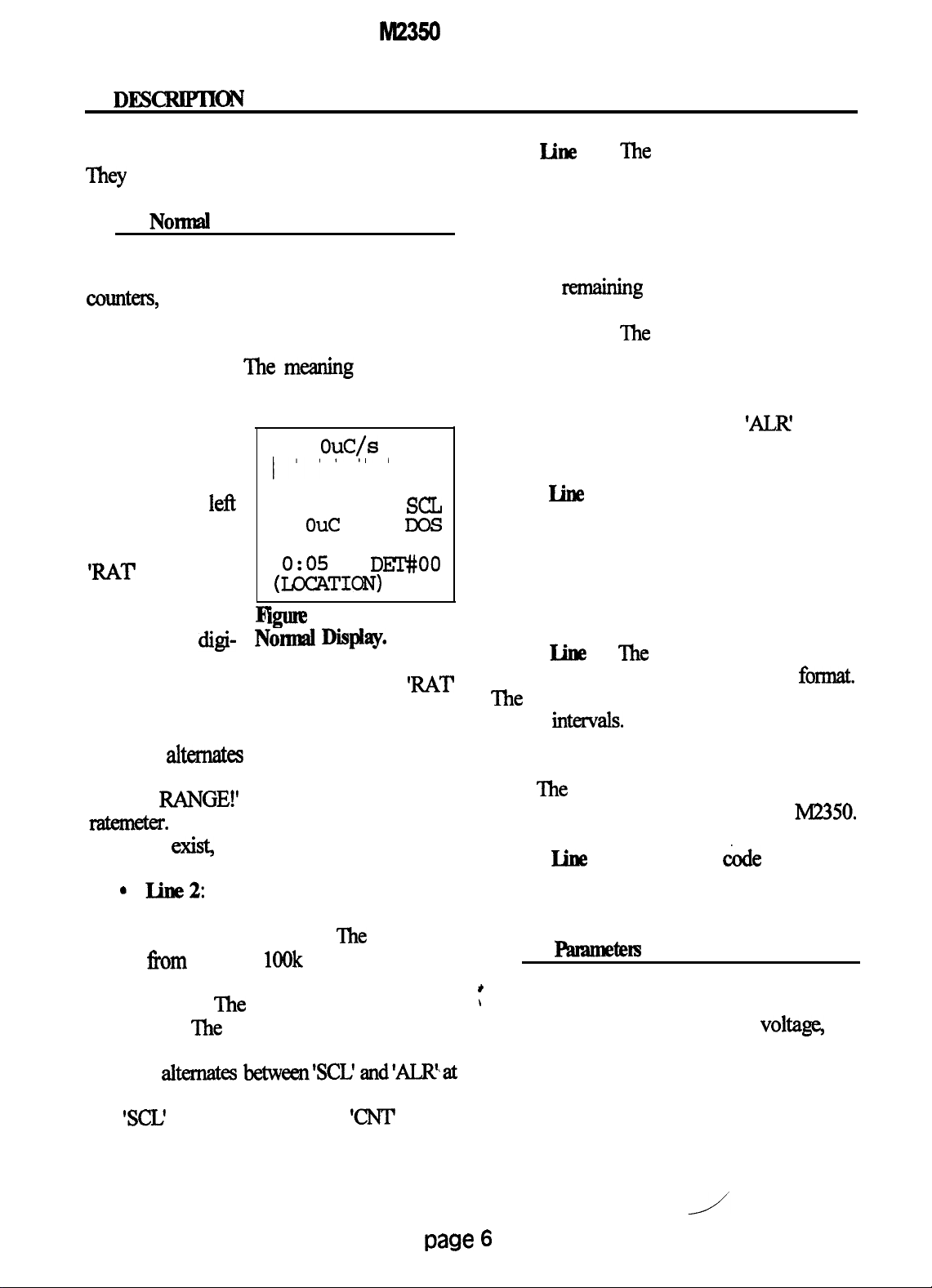
6.1 Nomal display
When the scaler is not counting the time
displayed is the count time for the scaler. If
The normal display mode displays all four
counters,
the time, the detector number,
the scaler is counting, the time displayed is
the time remaining until the count is done.
thelocation code and the number of samples
stored in the logging memory. The display is
shown in Figure 3. ‘Ihe meanjng of each line
follows:
l Line 1:
The digital
ratemeter is dis-
played in the
left
part of the line.
The message
‘RAT
indicates
that this is the
digital ratemeter.
If there is a digi-
0.
I'(
OuC!s
"
RAT
0
10
SEC
0.
out
4MIN DOS
0:05
(IXXTION)
iIgure
3.
DEX'#OO
#000
NOrmal DisplaY,
sa
SCL
tal ratemeter
alarm, the message alternates between ‘RAT
and ‘AIR at one-second intervals. If there is
a detector overload, the message ‘OVER
LOAD!’
reading. If there is an overrange, the message
‘OVER RANGE!’ alternates with the digital
ratemem.
alternata
with the digital ratemeter
If both overload and overrange
displayed on this line. The message ‘DOS’
indicates that this is the integrated dose. If
thee is an integrated dose alarm, the message
alternates between ‘DOS’ and
second intervals.
is displayed here. ‘The ‘DOS’ message is
always on and indicates that this is the
integrated dose timer. ‘The time displayed is
the elapsed time in minutes since the integrat-
ed dose started accumulating.
the left side of this line in the 24 hour format.
‘Ibe
second intexvals. If the battery voltage is 4.4
volts or lower, the message ‘LO BAT
alternates with the time at one second intervals. The right part of the line shows which
detector settings are beiig used by the M2350.
conditions exist, the overload message is used.
* Iine2:
Thefivedecadelogbargraph
is displayed on this line. The count rate is
always in counts per second
covers f?om 1 cps to
1OOk
cps.
‘Ihe
bar graph
in this line. The number of logged readings is
displayed at the right side of this line.
*
l
Line 3: The scaler readout is displayed
on this line. The message ‘SCL’ indicates that
this is the scaler. If there is a scaler alarm, the
message
al-
between’SCL’
and’ALR%at
one-second intervals. Between the scaler and
the ‘XL! message, the message ‘CNT appears
\
ratemeters, the scaler, the high
window, the battery voltage, the threshold, the
time, the date and the user identification
number. The display is shown in Figure 4.
The meaning of each line follows:
when the scaler is counting.
l
Line
4:
Tbe
scaler count time is
l
Line 5:
l
Line
l
Iine
‘Ihe
integrated dose readout is
‘ALR’
at one
6:
The integrated dose count time
7:
The
clock time is displayed at
colon blinks on and off at one-half
l Iine
8: The location
&de
is displayed
6.2 I’amneten display
The parameters display mode displays both
voltas
the
paw
6
Page 12

MZ350
Data Logger
l Lines 1
thmgh 4:
‘Ihe
same as in the
normal display
(section 6.1)
l Line 5:
The detector high
voltage and Gindow are displayed
on this line. If the
window is off, the window setting is replaced
by the message ‘OFF’.
0.
OuC/s
1 I I l I I
RAT
0
sa
10 SEC sa
0 W= OFF
E;=5.5
T= 100
0:05 l/01/90
(USER ID)
Rgure 4,
I%EUE&XS DI@~~Y.
?he detector serial
number is displayed on this
line.
The
this line displays
the code for the
display units. The
middlepartofthis
line displays the multiplier
l Iine 6: The battery voltage and
threshold
are
displayed on this line. If the
part of this line displays the code for the
display time base.
battery voltage is 4.4 volts or lower, the
message ‘LOW replaces the bat&y voltage.
high voltage and window setting. If the
l
Line 7: The clock time is displayed at
the left side of this line. It is in the 24 hour
format.
second
“Ihe
colon blinks on and off at l/2
intervals. If the battery
voltage is 4.4
volts or lower, the message ‘LO BAT
alternates with the time at 1 second intervals.
window is off, then the window setting is
replaced by the message ‘OFF’.
count time in seconds and the
setting.
‘Ihe right part of the line shows the date as
.rnonth
day, year.
bration constant used by the digital ratemeter
l
Une 8: The user identification code is
displayed on this line.
and the integrated dose.
is kept in counts per second internally and is
divided by the caIibration constant to provide
6.3
Detectordisplay
the actual readout.
l Line 3:
D)ZX'EmR
#00
MODEL
SER.#
U=7
M=O TB=O
HV=
0 w= OFF
CT= 10 T= 100
CC=1.000000e+00
9
Line 4:
lefi
part of
LT=O.000000e+00
Qlne
5.
ktector Display.
code.
The right
l
Line 5: This line displays the detector
l
Line
6:
This
line displays the
scaler
threshold
l
Line 7: This
line displays the
‘Ihe
digital ratemeter
cali-
The detector display mode displays the
current detector selection, the detector model
and serial numbers, display setup, high
voltage, window count time, threshold,
calibration constant, and detector dead time.
The display is shown in Figure 5. The mean-
deadtime.Thisnumb&susedtocorrectfor
dead time losses caused by the detector and
the M2350 dead time.
*
,
ing of each line follows:
l
Iine 1: This
line displays the current
detector whose settings are bemg used.
alarm and overload settings. The display is
shown in Figure 6. The meaning of each line
follows:
l
Line 2: The detector model number is
displayed on this line.
detector whose settings are being
paw
7
l
Line 8: This line displays the detector
6.4
Ahum disdav
The Alarm display mode displays the
l
Line
1: This
line displays the
curnznt
e
Page 13

M23!50
Data Logger
l Line 2:
This line shows
that the alarm settings are being
displayed.
l Line 3:
DEX'ECIQR
RAT LOOOe+09
Sal 999999
DOS
OVEiF!LOAD=
The digital
mtemeter
setting
alarm
is &+
Ggure
AhIlllDiSplrlly.
played on this
line.
l line
4: The
scaler alarm setting is dis-
played on this line.
l Iine
5: The
integrated dose alarm is
displayed on this line.
l Iine
6: This line is blank.
#00
l.OOOe+09
OFF
6.
l Line 4:
The type of data
logged is
played here
dis-
DEX'FCIOR
#00
RA-
(ratemeter, scaler,
integrated
i&e).
l Line 5:
The count that
0:05 l/01/90
I
figune
7.
W~~Di@aY.
I
was logged is displayed here.
l
Iine6:
logged, this line is blank.
Iftheratemeterreadingwas
Ifthe
scaler reading
was logged this line is the scaler count time
in seconds. If the integrated dose reading was
logged, this line displays the accumulated time
in minutes since the
intern
dose was
started.
l line
of
p.A
is
disabled,
7:
The overload setting in tenths
is displayed on this line. If the overload
the setting is replaced with the
time (24 hour format) and the date (month,
day, year) that the reading was taken.
message ‘OFF.
l Iine
6.5 Lagged
8:
Jhis
daba dispiay
line is blank.
specified has not
beenusedfordata
Tbe lo&
logged data
data display mode displays the
tirn
the
selected
sample. The
logged data consists of the sample number,
the location
code,
the detector
USBCS,
the
logging yet, the
display looks like
Figure 8.
logging mode, the count, the count time, the
time, and the date. ‘Ihe display is shown in
Figure 7.
l Iine 1: The sample number is dis-
‘Ihe
meaning of each line follows:
*
,
played in this line.
.
W
in this line.
2: The location code is displayed
both ratemeters, the scaler, the recycle count
status, the
Joggion code and the number of samples
l Iine3:Thedetectorwhosesettings
were used to log the data is displayed here.
stored in the logging memory. The display is
shown in Figure 9.
follows:
l Iine
l LineWIhislineisblank.
7: This
line displays the clock
If the location
!~!!!!111111111
. . . . .
*...
INVALID
IK24TION
lllllllllllllll
. ..*...........
Flgm
8.
hvalidI.malionDisplay.
6.6 Recycle data
display
The recycle data display mode displays
tinq
the detector number, the
‘Ihe
meaning of each line
Page
8
Page 14

lVt2350 Data Logger
l Lines 1
thmugh
4: The
same as in the
normal display
(section 6.1).
l Line 5:
This line displays
the
current cycle
that is active, the
?. OuC/s
, I
I
0
RAT
SCL
10 SEC SCL
CYC 1 OF 1 ROOO
DELAY
0:05
60 SEC
(DFT #)
(UICATI~N) #ooo
F@un2
Recycle Dab
9.
Display.
the setup information for the recycle counts.
This consists of the number of cycles enabled,
the detector each cycle will use, the delay
time before the data is logged, the logging
mode, and the number of recycles. The
display is shown in Figure 11. The meaning
of each line follows:
number of cycles
in each recycle, and the number of recycles
that have been completed.
This
that the recycle
l Iine 6:
time left. before the next cycle is started.
l
Line 7: The clock time is displayed at
the lefi side of this line. It is in the 24 hour
format. The colon blinks on and Off at
one-half second intervals. If the battery
voltage 4.4 volts or below, the message ‘LO
BAT
alternates
intervals. The right part of the line shows
which detector setting is being used by the
M2350.
‘Ihis
line displays the delay
with the time at 1 second
countsetupdatais
beiig displayed.
‘Ihis
the setup informa-
tion for cycle 1.
The cycle number
is displayed fust. Next is the detector used by
this cycle. The next number is the delay time
before the data is logged. The last number on
this line is the logging mode that will be used.
6.7 Recycle setup display
‘The recycle setup display mode displays
l Line 1:
line shows
3NmENABLED
4NurEwmwD
5NmExaBm
l Line 2:
line shows
figure
10.
WcIe Sebup Display.
l
Line 8: The location code is displayed
in this line. The number of logged readings is
displayed at the right side of this line.
tbe same information as line 2. If the particular cycle is not enabled, the message ‘NOT
ENABLD
If the recycle mode is disabled, lines 5 and
information.
6 will display the message ‘RECYCLE
DISABLED’.
allowed is displayed here.
l Iines
3 thmugh 7:
?Ihese
lines display
is displayed instead of the cycle
l Iine 8: The number of recycles
paw 9
Page 15
M23!50 Data Logger
‘Ihe M2350
is controlled by either the
optical wand or the serial I/O. All commands
to control the
either the wand or the serial
M2350
can be executed by
I/O.
Please refer
to Sections 11 and 12 for fbrther information
regarding the setup and operation of the
optical wand and the serial
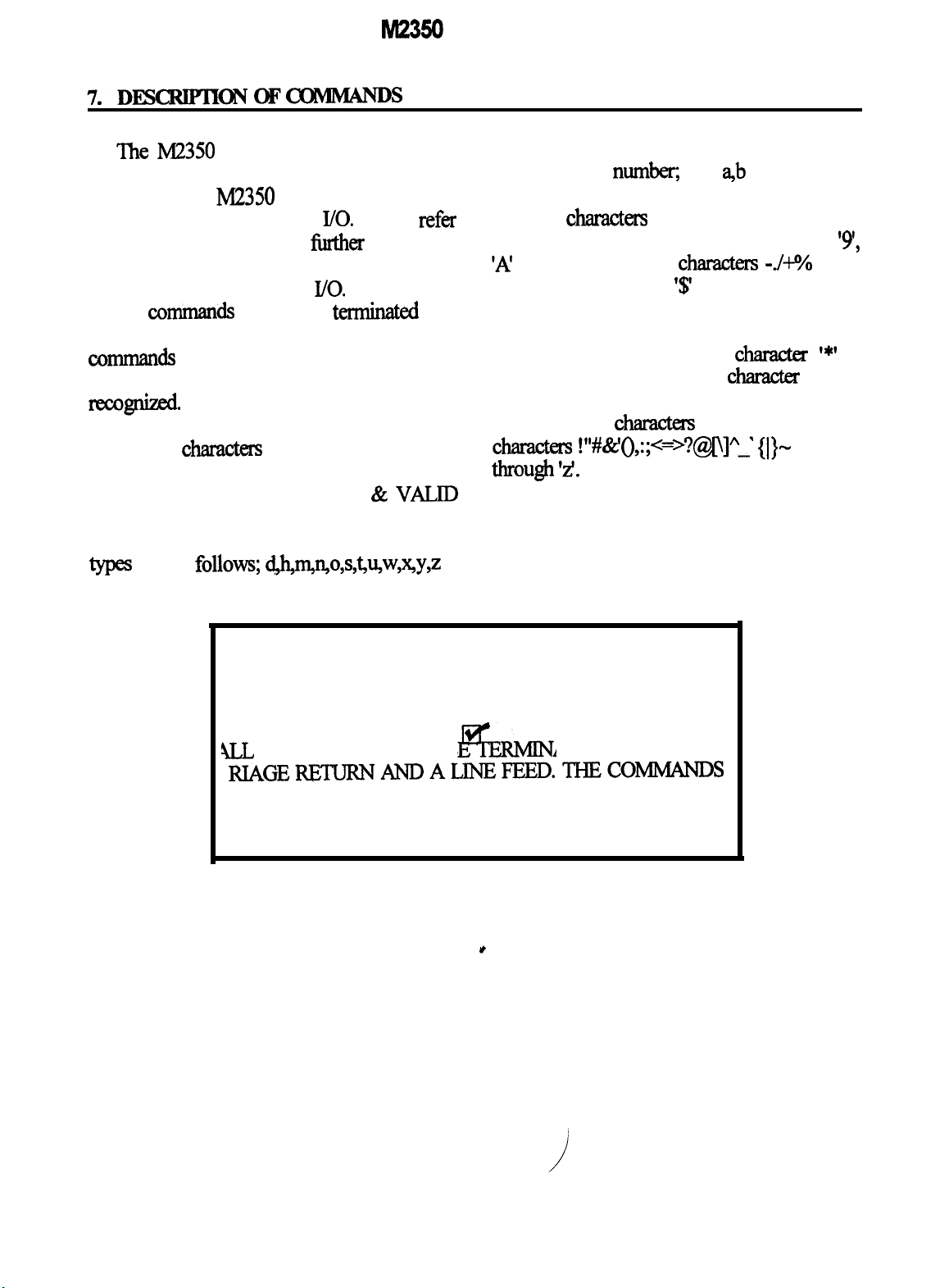
All
wnmands
need to be
I/O.
termhted
with
a carriage return and then a line feed. The
tzanmands are all upper case. If lower case
commands are used, they will not be
Ilzcow.
In the command descriptions below, the
lower case characters in the COMMAND line
are supplied by the user. The lower case
letters under the RESPONSE &
VALID
are integer values; f is a single precision
floating point
meric string. With the alphanumeric string, the
following
serial I/O and the optical wan& ‘0’ through
‘A’
space. The character
when multiple commands are to be sent at one
time or as the separator code when dumpmg
the logged readings. The
reserved as the start and stop charackr for the
bar codes. If only the serial I/O is to be used,
the following
charades
tllrougll ‘2.
CHARACTERS are the values returned in
response to the read commands. The variable
types
are as
follow 4hmQo,s,6Qw,%,y,z
numb,
charactw
and
a,b
are alphanu-
are valid for use with the
‘9’,
through ‘Z’, and the characters -./+?4 and a
‘$’
is reserved for use
chamcter ‘*I
characters
are also valid; the
!“#&‘(),:;<=>?@o]A-’ {I}-
is
and ‘a’
NOTE
ILL COMMANDS MUST B
ATEDWITHACAR
RIAGE~TURNANDALJNEFEED.‘IHECOMh’IANDS
MUST BE UPPER CASE
NOTE
i
page10
Page 16
M2350
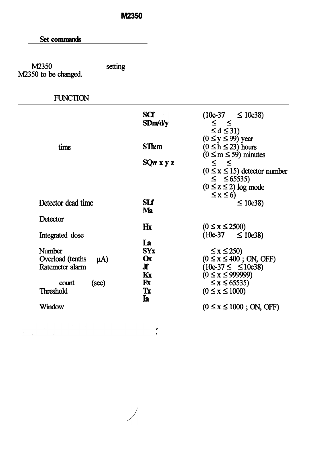
7.1 !ktconlnmKk
This type of command will send data to
the
M2350
M235otobechanged.
which allows a
SET FUNC’IION COMMAND VALID CHARACTERS
setting
in the
Data Logger
Calibration constant
Clock date
Clock time
Cycle count
Cycles per recycle
Detectordeadtime
Detector model
Detector serial number
High voltage
Integrated dose alarm
Location code
Numher of recycles
o-&Tx&g(m~ of
scaler alarm
Scaler
‘Ihreshold
User I.D. number
wmdow
c43unt
time
pA)
@cc)
Slkm
SQWXYZ
SRX
SLf
lb
Na
Hx
Pf
I.2
SYX
ox
Jf
Ki
I%
TX
Ii
wx
(Me-37
(1 I m I 12) month
(1 Sd
(OIyI99)year
(OIh123)hours
(O,<mI59)minutcs
(1 I w 5 6) cycle number
(OIxI15)detectornumber
(0 I y
(OIz<2)
(1
(Me-37 If <
(alphanumeric, 9 char)
(alphanumeric, 9 char)
(05x52500)
(l&37
(alphanumeric, 10 char)
(1
(OIxUOO;ON,OF’F)
(lb37
(OSx999999)
(0
(01x~lOOO)
(alphanumeric, 15 char)
(O1x51OOO;ON,OF’F)
If I
531)
day
265535)
logmode
IXG)
If I
5xs250)
< f I
5x165535)
lOe38)
seconds delay
lOe38)
lOe38)
lOe38)
page 11
Page 17
MB!30 Data Logger
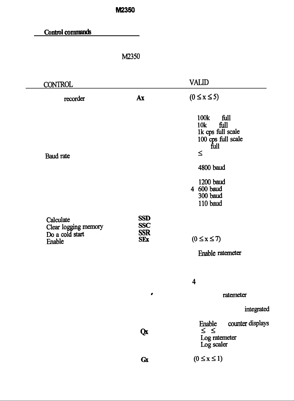
7.2 Contml
commands
This type of command may or may not
require data with it and will cause the M2350
to do something.
cmTRoL
Analog
FUNCTION
recorder
mode
Baudrate
Calculate cal constant
Calculati:
dead time
COMMAND
Ax
Bx
SSK
~=r~$n”y
Enable
counter displays
Logareading
Ratemeter response
S!3R
SEX
Gix
VALID CHARACTERS
(05x15)
0 5 decade log
1
1OOk
cps
111
scale
2
1Ok
cps
111
scale
3
lkcpsfblhcale
4 1OOcpsfbllscale
5
10 Ml scale
cps
(0 1. x 5.6)
0
96oobaud
1
48OObaud
2 24OObaud
3
12OObaud
46oobaud
5
3oobaud
6 11Obaud
(OSxS7)
0 All counter displays off
1 Ehble
ratema
display
2 Enable scaler display
3 Enable ratemeter and scaler
display
4 Enable integrated dose
display
5 Enable
ratemeter
and in-
tegrated dose display
6 Enable scaler and
integmted
dose display
7
l&able
all
counm displays
(0 5 x I 2)
0 LQgI-tmeer
1
Logscaler
2 Log integrated dose
(05x51)
page12
Page 18
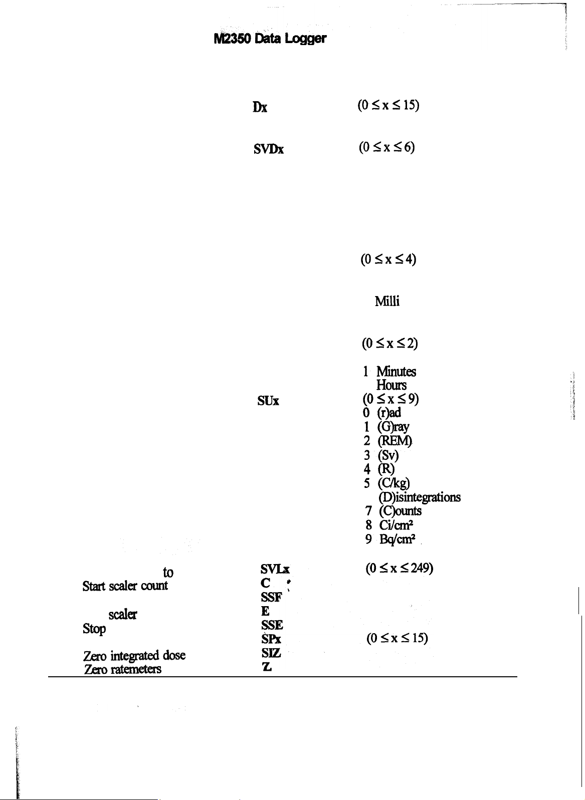
Recall detector settings
Reset alarms
Dx
X
0 slow response
1 fast response
(OlxIlS)
Select display mode
Select display multiplier
Select display time base
Select display units
SVDX
SMX
SBX
!3UX
(OIxS6)
0 Normal display
1
Parameters display
2
Detector display
3
Alarm display
4 Logged data display
5 Recycle data display
6
Recycle setup display
(OIx14)
0 Autorange
1
Micro
Milli
2
3
none
Kilo
4
(OIxS2)
Seconds
0
ll%lW
2
Hours
(OSxS9)
(r)ad
0
1
@WY
set log location to view
startscalercoutnt
Start the recycle
stop
Scala
count
Stop
the
recycle
store detector settings
zerointegrateddose
zero-
ip
4
0
5
uu
6
(D)isintegrations
;: LEE?@
9Ek+n.
Y
page 13
Page 19

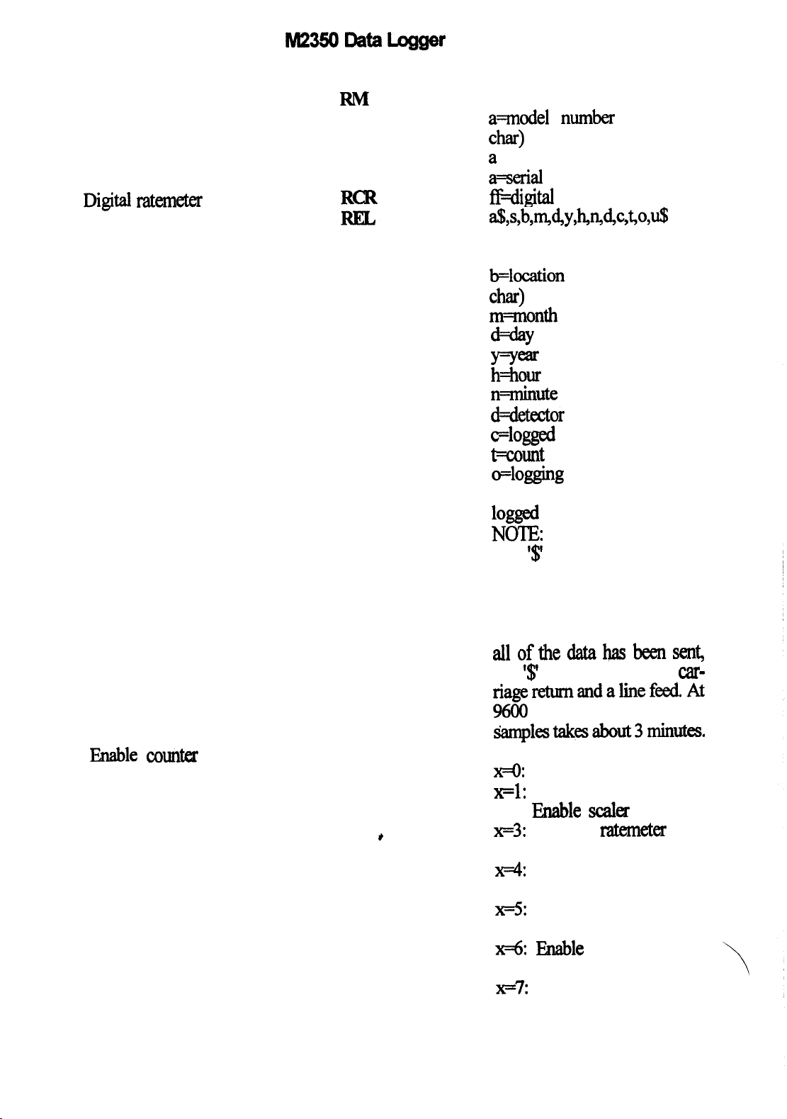
7.3 Read commands
lid2350
Data Logger
‘These
commands
will cause the desired
datatobesentout~serialvo.
READFUNCTION
Analog recorder
mode
Bar graph ratemeter
Baud rate
Battery voltage
calibration constant
Clock date
Clock time
Cycle
Cycles per recycle
Detector dead time
counf
COMMAND
RA
RT3
RST
RSL
RESPONSE & VALID
CHARACTERS
k0: 5
decade log
x=1: 1OOk
~2:
x=3:
x74:
x=5:
cps
1Ok
cps
111
lk cps
Ml
100 cps
10 cps
111
@ll
scale
scale
111
scale
scale
scale
f
Margraphratem~
X
?FOZ%OObUd
x==l: 4800 baud
~2:
~3:
2400
1200
baud
baud
X4:6OOlXUd
x3:
300 baud
x76: 1lObaud
f
f!4xaay
f
+calibration
voltage
constant
Q4Y
m=mMh
WY
y-year
4m
h==hours
nmlinw
(1 SwW6)cyclenumber
%YJ
x=+&ctor numbzr
y=seconds
delay
Flog mode
x
x=number
of cycles per
If”y”1”
Head
time
page 14
Page 20
M2350 Data Logger
Detector model
Detector Serial number
Digital ratemeter
Dump logging memory
Enable uxn&x displays
RN
RSE
a
a=model number
(up to 9
Char)
FLserial
ff4igital
number (up to 9 char)
ratemeter
dWwvWwAc,co,~
a=I.D number (up to 15 char)
s-sample number
b=location
code (up to 10
Char)
m==month
sample logged
d=day sample logged
y=year sample logged
h=hour sample logged
mnimte
d==detector
Flogged
+count
sample logged
number
count data
time of logged data
o=logging mode
FM2350 status when data
logsed
NOTE:
The
‘$’
character signifies that
a logging location% data has
been sent. The variable string
except for ‘a’ is repeated for
each logging location. When
alloflhedatahasbeensen~
the
‘$’
is followed by a
carriagereturnandalinefeed.At
9600
baud, dumping all 250
&implestak~about3minutes.
X
*
All counter displays off
x=1: Enable ratemeter display
x=2:
Wle scak
~3:
t
Enable
display
mtemeter
and
scaler display
x=4 Enable integrated dose
display
~5:
Enable ratemeter and integrated dose display
x=6
F5nable
tegrated dose display
~7%
Enable all counter
scaler and in-
\
displays
page 15
Page 21
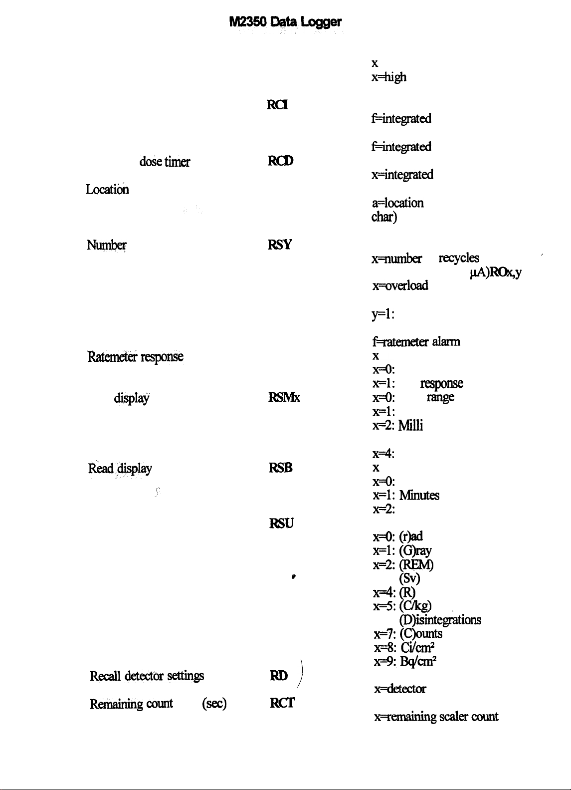
High voltage
RH
Ligh
voltage
Integrated dose
Integrated dose alarm
Integrated
do& her
(min)
Locatkh code
Ne
of recycles
Ratemeter alarm
‘Ratemeter;response
Read
display
R&a+lisplay
multiplier
time base
Read display units
R.ecalldetector~gs
RCI
RP
RL
RSY
RJ
RG
RSMX
RSU
*
RD
!
f
+integrated dose
f
&integrated
dose alarm setting
x
x=integrated
dose timer
a
a=location
code (up to 10
Char)
X
x?ilumber
Overload (tenths of
x=overload
of
ITcycles
setting
allowed
@)R%y
y=o: overload disabled
y=l:
overload enabled
f
jL+amaa alarm
E&o:
slow response
x=1:
fast
response
~0:
Auto
x=1:
Micro
x72: Mllli
x=3:
x74:
Kilo
t=O:
Seconds
x4:
x=2 Hours
X
range
none
Min-
setting
x=0: (r)ad
x=1: (G)ray
x=2(REryl)
x=3: (Sv)
x4 (RI)
XFS:
(ckg)
x=6:
(D)isintegAtions
x=7: (C)aunts
x=8: Ci/d
?F!mqd
X
’
Remaining count
time (set)
X
?FEmaEngscal~count time
page 16
Page 22

SC&
scaler alarm
Scaler count time
Soitware
version
Threshold
User I.D. number
’
Window
IL42350
status
(se@
RCS
RK
RF
RT
RI
RW
X
xwaler contents
X
x=scaler
alarm setting
Xer count time
kersion
number (up to 16
Char)
kthreshold
k1.D. number (up to 15 char)
%Y
x+ndow
y=O:
window off
y=l:
window on
k2350 statlls
8
bit number
defjned
as
follows
Bit 0: n&meter alarm
Bit 1:
scaler alaxm
Bit 2: integrated dose alarm
Bit 3: scaler overflow
Bit 4.: integrated dose
overflow
Bit 5: low battery
Bit 6:
ovenrange
Bit 7: overload
NOTE:
‘Ihe
display is in
decimalf~andmustbe
converted to a bii 6
quivaknt.
the bit is
the bit is “not
If a bii bit is 1,
“seP;
if the bit is 0,
set”.
page
A7
Page 23

READ FUNCTION COMMAND VALID CHARACTERS
8.
tXMMANDUSAGE
M23!50
Data Logger
The M2350
customize
applications. This is done by issuing a series cmmands to configure and use the
ummands allow the user to
the
M2350
for particular
specific operating needs. The following
examples show how to use the
M2350
Ivl2350.
of commands to the M2350 to set it up for the The examples are set up to list the function
desired, the actual M2350 command, and the
M2350
response.
‘Ihe
examples also do not
show the carriage retum and line feed that are
needed at the end of the command. They ate
not shown because their entry method depends
on the type of entry equipment used.
NOTE
ALL COMMANDS
MSJS
Ar
E TERMINATED WITH A
CARRIAGE PETURN AND A LINE FEED. THE COM-
MANDS MUST BE UPPER CASE
NOTE
8.1Scanthroughthedisplaymodes
The following command examples will
show the various display modes of the
M2350.
FUNCTION
Select the normal display mode.
Select the parameters display
mode.
Select the detector display mode. SVD2
Select the alarm display mode.
page 18
For a detailed explanation of the displays,
refa
to section 6.
COMMAND
Svlp
\
SVDl
M2350
The
RESPONSE
M2350
display should
now look like Figure 3.
The
M2350
display should
now look like Figure 4.
The
M2350 display
should
now look like Figure 5.
svD3
The
M2350
display should
Page 24

lM2SODataLogger
Select the logged data display SW4
mode.
Select the recycle data display SW5
mode.
Select the recycle setup display
mode.
8.2
Set various detector settings
SW6
now look like Figure 6.
The
M2350
display should
now look like Figure 7 or
Figure 8.
The
M2350
display should
now look like Figure 9.
The
M2350
display should
now look like Figure 10.
The following command examples will
show the how to set some of the detector
FUNCTlON
Select the
pammeters
display
co-
SvDl
mode.
Set the high voltage to
9OOV.
Set the threshold to 500.
Turn the window on.
Set the window to 50.
Turn the window off.
Set the clock to
Set the date to
11:23.
12W90.
Select the detector display mode.
Set the calibration constant to
1,000,000.
Set the calibration constant to 1.
Setthedeadtimeto25pS.
SetthedeadtimetoOyS.
Set the model to 44-2.
settings. The ccmmands not shown work in
the same fashion.
M2350
The
RESPONSE
M2350
display should
now look like Figure 4.
The high voltage should now
read 9oov.
The threshold should now read
500.
The
window should now be
on and display a number.
The window should now read
50.
The window should now be
Off.
The time should now display
11:23.
The date should now display
12/12/90.
The
NJ2350
display should
now look like Figure 5.
The calibration constant
should now be
1.m.
The calibration constant
should now be
1..
‘Ihe dead time should now be
2.5OOOOOe45.
The dead time should now be
0.
The model should now display
44-2.
page19
Page 25

M23!iO
Data Logger
Set the serial number to
Select the alarm display mode.
Set the ratemeter alarm to Jle4
10,000.
Set the scaler alarm to 5647.
Set the integrated dose alarm to
1223.
N12Z3
svD3
KS47
P2Se5
250,000.
Set the ratemeter alarm to le9.
Set the scaler
Set the integrated dose alarm to
M.
Turn the overload on.
Set the overload to
Twn the overload off.
alann
to 999,999.
5.0@
Jle9
K999999
Ple9
The serial number should now
display
The
now look like Figure 6.
The ratemeter alarm should
now be
The scaler alarm should now
1223.
M2350
display should
1.OOOetO4.
be5647.
‘l’he
integrated dose alarm
should now be
The
ratemeter alarm should
nowbe1.OOOeHB.
The sealer alarm should now
he999999.
The integrated dose alarm
should now be
The overload should now be
on and display a number.
The overload should now read
2.5OOei-05.
1.M.
50.
The overload should now be
Off.
8.3
The following command examples will
show how to read some of the detector
settings. These examples assume a termbal is
being used that can display the data sent
Read
vtious
FUNCTION
Select the parameters display
mode.
Set the high voltage to 500V.
Read the high voltage.
Turn the window on
Set the window to 50.
detector
setiims
COMMAND
SVDl
l%XM?
RH
mN
from the M2350. A command will be given to
set the setting to the desired value and then
the setting will be read to verify the value.
The responses to the read commands
explained in section 7.
M2350
‘Ihe
now look like Figure 4.
The high voltage should now
read
The
‘9oo’outtheserialpoti
The window should now be
on and display a number.
The window should now mad
RESPONSE
M2350
Nov.
M2350
display should
will now send
are
50.
page20
Page 26
M23!50 Data Logger
Read the window setting.
Turn the window
OK
Read the window setting.
The following examples show how to set
RW
WOFI?
RW
set, the user identification number will be pro-
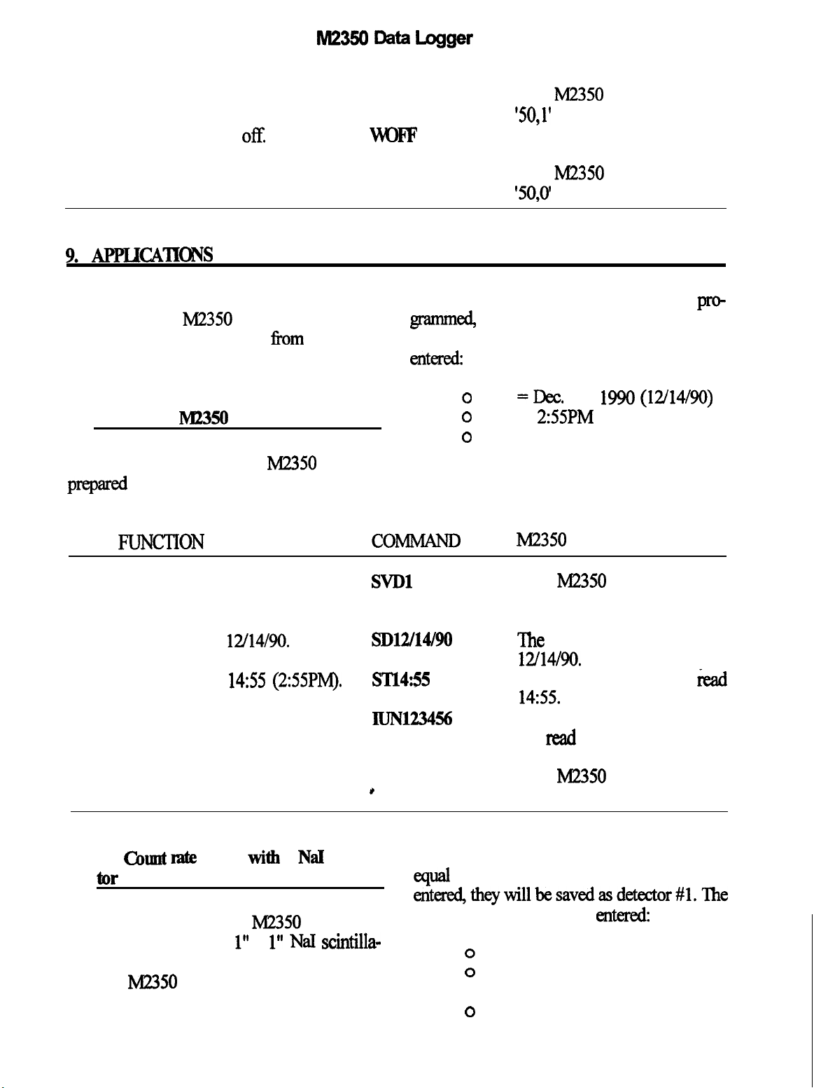
up and use the M2350 in various situations. grammed,
The possible uses range
from
a simple
ratemeter to a data logging system using
cleared. The following settings will be
entd
multiple probes.
0 date
9.1 General
MI2350
setup
o time =
0
In this example, the
M2350
will be
prepared for further set up. The clock will be
The
M2350
will now send
‘50,l’ out the serial port.
The window should now be
Off.
The
M2350
'50,o'
out
will now send
the
serial port.
and the logging memory will be
=Dec.
14,
1990 (12/14/90)
2:55PM
user id = UN123456
FUNCTION
Select the parameters display
co-
SVDl
mode.
Set the date to
Set the time to
12/14/90.
14:55
(2:55PM).
Set the user I.D. number to
m1u14/90
sTl4:55
IUN123456
UN123456,
Select the normal display mode.
9.2
Count mte
meter
witi
a Nal scintilla
for
SVDO
*
,
time correction and the calibration constant
equal
entered,theywillbesavedasdetector#1.The
For this example, the M2350 will be set
following settings will be
up to use an LMI 44-2 1” x 1” NaI scintilla-
tor. This example also assumes
general
MB50
setup has already been done.
that the
The display is in counts per minute with live
M2350
The
RESPONSE
M2350
display should
now look like Figure 4.
‘Ihe
date should now read
12/14/90.
The time should now
read
14:55.
The user identification should
now read UN123456.
The
M2350
display should
now look like Figure 3.
to 1. After the settings have been
enteredz
0 High voltage = 700v
o
Threshold = 1003) Window =
Off
o Window = off
page21
Page 27
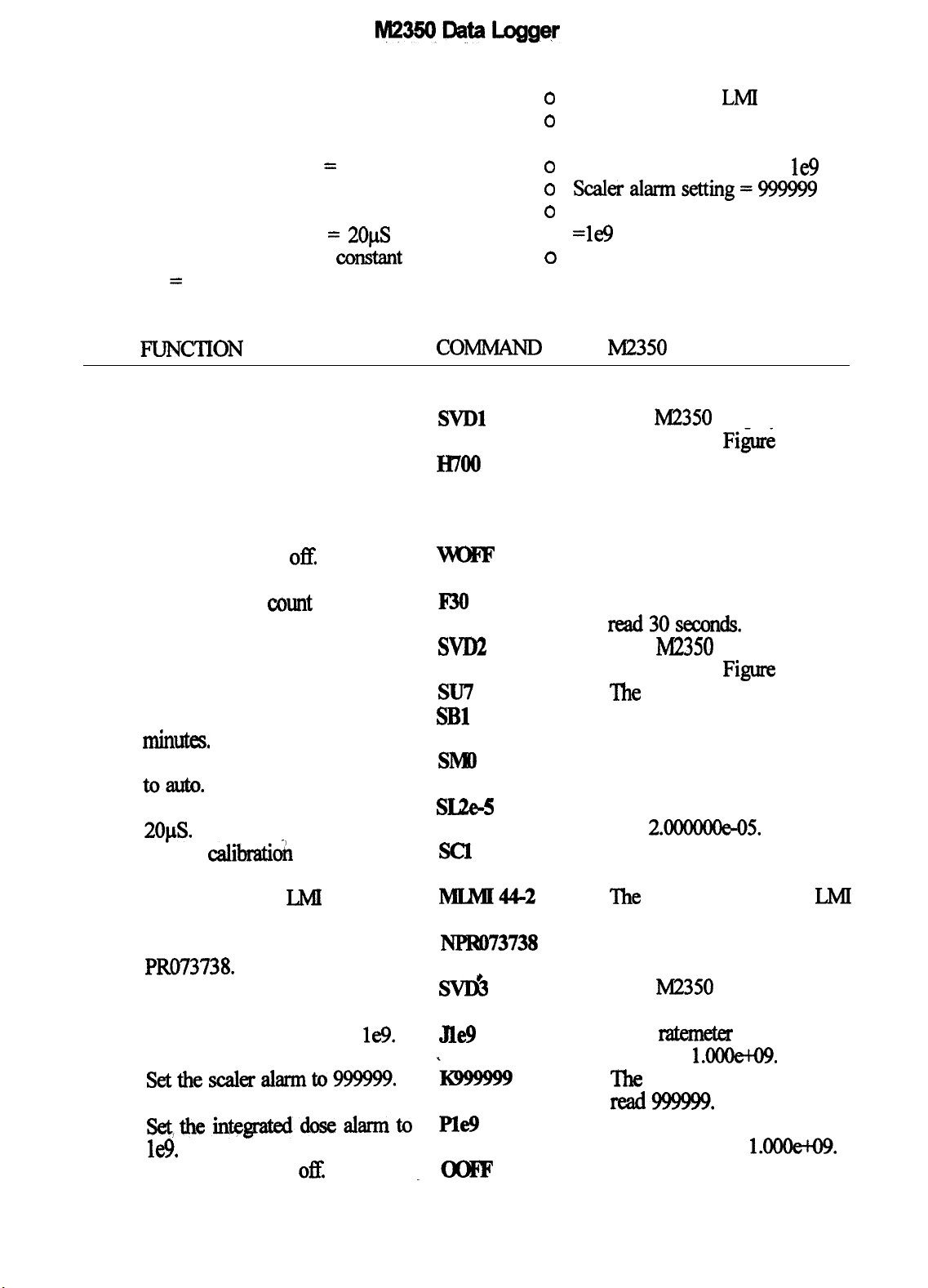
0
Scaler count time = 30
seconds
0 Display units = counts
o
Display time base = minutes
0 Display range multiplier =
auto
o Detector dead time =
o Detector calibration cunstant
=
1
2OpS
0 Detector model =
0 Detector serial number =
PRO73738
0 Ratemeter alarm setting =
0 scaleralarmsetting=m
0 Integrated dose alarm setting
=le9
0 overload current = off
LMI
44-2
l&
l?‘UNCTION
Select the parameters display
mode.
Set the high voltage to 700V.
Set the threshold to 100.
Turn the window
Set the scaler
seconds.
Select the detector display mode.
offI
count
time to 30
set the readout units to counts.
Set the readout time base to
mill-.
Set the readout range multiplier
toauto.
Set the detector dead time to SUe-5
2o@s.
Set the
Set the model to
Set the serial number to
PRO73738
Select the alarm display mode.
Set the ratemeter alarm to le9.
Setthescaleralarmto999999.
Settheinte~dosealarmto
l&.
Turn the overload
calibrati&
constant to 1.
IMI
44-2.
off.
COMMAND
SVDl
IWO0
Tloo
F30
SVD2
su7
SBl
SMO
SCl
MLMI44-2
Nl?RO7373??
SW&
Jle9
i99!ww
Ple!J
.-
M2350
The
now look like
The high voltage should now
read 700v.
The threshold should now read
100.
The window should now be
RESPONSE
M2350
display should
Fig&
4.
Off.
The count time should now
read3oseJcmds.
The
M2350
now look like Figum 5.
‘Ihe units should now read 7.
‘The time base should now
read 1.
The range multiplier should
now read 0.
The dead time should now
read
2.000000e-05.
The calibration constant
should mad 1.
‘Ihe
model should read
44-2.
The serial number should now
read PR073738.
The
M2350
now look like Figure 6.
‘The rakmekr alarm should
now read
‘Ihe scaler alarm should now
read!299999.
‘The integrated dose alarm
should now read
The overload should now be
display should
LMI
display should
1AMOe-W.
MOOe-KB.
page 22
Page 28

M2350
Data
Save the settings as detector 1. SPl
Select the normal display mode.
Load detector #l settings.
SVDO
Dl
Logger
Off.
The
settings have now been
saved as detector
The IV2350
#l.
display should
now look like Figure 3.
This step is not needed, but is
included to show how to recall
the settings of detector
#l.
The setup of the M2350 for the count rate dose.
meter is now complete. The M2350 can now
beusedasacountratemeterorascaler.~~
following commands will show how to start
not effect the settings saved under detector
because the save
will not be used in the following example.
the scaler, stop the scaler, change the count
time, and zero the ratemeter and integrated
FUNCTION
Select the normal display mode.
Start the scaler counting.
Stop the scaler.
Set the count
the
to 10 seconds.
Start the scaler counting.
zerotherat~.
Reset the integrated dose.
coMM44ND
SVDO
C
E
FlO
C
Z
SlZ The integrated dose and the
*
The
changes made to the count time will
parameta
M.2350
The
M2350
command (SPx)
RESPONSE
display should
now look like Figure 3.
‘The M2350
should now start
cQunting.
lhe
M2350
should stop counting.
‘The
count time should read 10
seconds.
‘The M2350
should now start
counting.
‘Ihe
digital
barograph
both
rateme
ratemeter should
zm
and then resume
and the
normal operation,
integrated dose timer should
zeroandthenresumenormal
operation.
#l
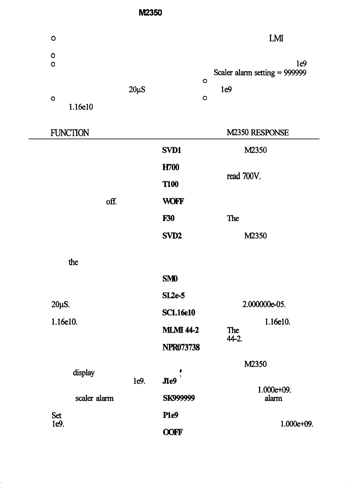
9.3
MicmR
meter with a
NaI t&till&r
provide the direct readout in R per hour.
the settings have
For this example, the
II42350
will be set
up to use an LMI 44-2 1” x 1” NaI scintilla-
tar,
This example also
geneml Me2350
setup has already been done.
assumes
that the
saved as detector
will be entered
The display is in R per hour with live time
correction and the calibration constant is set to
page 23
been en-
#2.
The following settings
0
High voltage =
o
Threshold=1OO
o Window = off
Mer
they will be
7OOv
Page 29
M2350
0
Scaler count time = 30
seconds
o
Display units = R
0 Display time base = hours
o Display range multiplier =
auto
o Detector dead time = 20~s
0 Detector calibration constant
=
1.16elO
Data Logger
0 Detector model = LMI 44-2
0 Detector serial number =
PRO73738
0 Ratemeter alarm setting =
0 scalerdarmsetting=999999
o
Integrated dose alarm setting
= le9
0 overload current = off
le9
FuNCTlON
Select the parameters display
mode.
Set the high voltage to 700V.
Set the threshold to 100.
Turn the window
Set the scaler count time to 30
seconds.
Select the detector display mode.
Set the readout units to R
Set
.the
readout time base to
hours.
Set the readout range multiplier
to auto.
Set the detector dead time to
ofI
2ops.
Set the calibration constant to
1.16elO.
Set the model to LMI 44-2.
Set the serial number to
PR073738.
Select the
alarm display mode.
Set the ratemeter alarm to le9.
Set the scaler
Set the integrated dose alarm to
le9.
Tum the overload off.
ahn
to 999999.
COMMAND
SvDl
Hmo
no0
F30
su4
SB2
sue-5
Scl.16elO
MLlw44-2
svD3
*
Jle9
’
SKgggggg
Ple9
M2350
The
now look like Figure 4.
The high voltage should now
RESPONSE
M2350
display should
read7OOv.
The threshold should now
read 100.
The window should now be
Off.
The
count time should now
read
30
seconds.
The
M2350
now look like Figure 5.
The units should now read 4.
The time base should now
read
2.
The range multiplier should
now read 0.
The dead time should now
read
2.000000s05.
The calibration constant
should read
The model should read LMI
display should
1.16elO.
44-2.
The serial number should now
read PR073738.
The
M2350
now look like Figure 6.
The ratemeter alarm should
now read 1.000&09.
‘The scaler
read999999.
‘l-he integrated dose alarm
should now read
The overload should now be
Off.
display should
ahnn
should now
1.OOOetO9.
page 24
Page 30

M2350
Data Logger
Save the settings as detector 2.
Select the normal display mode.
Load detector #2 settings.
SP2
SVDO
D2
The setup of the M2350 for the micro-R
meter is now complete. The operation of the
M2350
is the same as in the application
above.
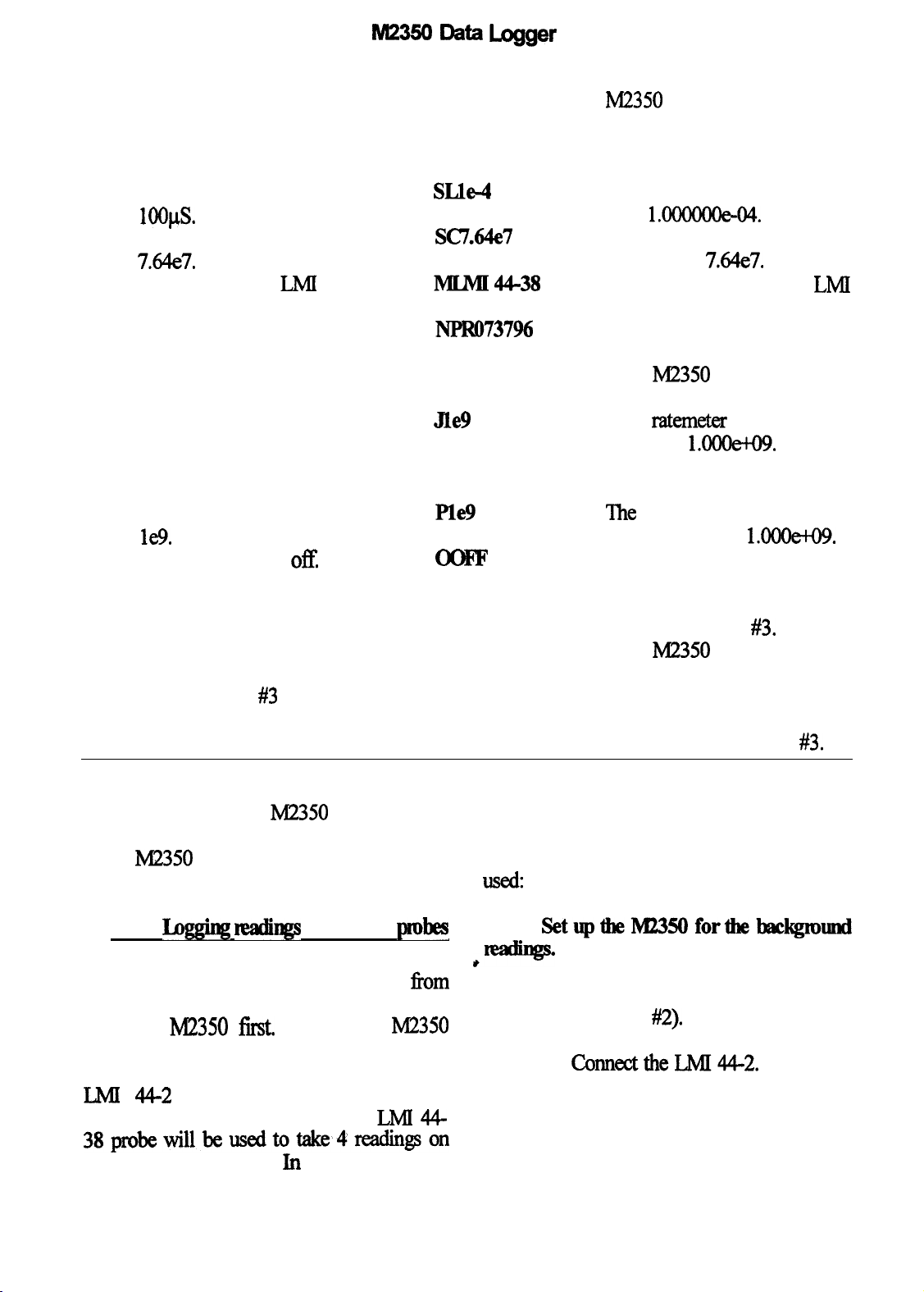
9.4
Survey
meter with a GM detector
For this example, the M2350 will be set
up to use an LMI 44-38 G-M detector. This
examplealsoassumesthatthegeneralM235O
setup has already been done. The display is in
R per hour with live time correction and the
calibration constant is set to provide the direct
readout in R per hour. After the settings have
been entered, they will be saved as detector
#3.
The following settings will be
enteredz
The settings have now been
saved as detector
The
M2350
#2.
display should
now look like Figure 3.
‘This step is not needed, but is
included to show how to recall
the settings of detector
0
High voltage = 900v
0
Threshold = 500
0
Window
0
Scaler count time = 6 seconds
0
Readoutunits=R
0
Readout time base = hours
0
Readout range multiplier =
auto
0
Detector dead time =
0
Detector calibration constant
=7.64e7
0
lletector model = LMI 44-38
0
Detector serial number =
= off
lOOuS
PRO73796
0
l3ammx
0
scaler alarm setting = 999999
0
Integrated dose alarm setting
alarm setting = le9
=le9
0
overload culrent = off
#2.
FUNCTlON
Select the
parame&s
display
COMMAND
SVDl
mode.
Se
the high voltage to
9OOV.
Set the threshold to 500.
H900
*-
Turn the window off.
Set the scaler count time to 6
I%
seconds.
Select the detector display mode.
SetthereadoutunitstoR
SVD2
su4
Set the readout time base to SB2
hours.
page25
M2350
The
RESPONSE
M2350
display should
now look like Figure 4.
The high voltage should now
read 9oov.
The threshold should now
Rad500.
The window should now be
Off.
The
count
time should now
read 6
The
seconds.
M2350
display should
now look like Figure 5.
‘The units should now read 4.
‘The time base should now
read 2.
Page 31
MZ350 Data Logger
FUNCTION COMMAND
Set the readout range multiplier
SMO
to auto.
Set the detector dead time to
SLIe-4
loops.
Set the calibration constant to
SC7.64e7
7.64e7.
Set the model to LMI 44-38.
Set the serial number to
PR073796.
Select the alarm display mode.
Set the ratemeter alarm to le9.
Set the scaler alarm to 999999. SK999999
Set the integrated dose alarm to
le9.
Turn the overload 0%
Save the settings as detector 3.
Select the normal display mode.
Load detector #3 settings.
MLlw44-38
NPRO73796
svD3
JYle9
Ple9
SF.3
SVDO
D3
Id2350
RESPONSE
The range multiplier should
now read 0.
The dead time should now
read
1.m04.
The calibration constant
should read 764e7.
The model should read LMI
44-38.
The serial number should now
read PR073796.
The
M2350
now look like Figure 6.
The
ratemeter
now read
The scaler alarm should now
read999999.
The
integrated dose alarm
should now read
The overload should now be
Off.
The settings have now been
saved as detector
The
M2350
now look like Figure 3.
This step is not needed but is
included to show how to recall
the settings of detector
display should
alarm should
l.OOOe+O9.
1.m.
#3.
display should
#3.
The setup of the
M2350
for the G-M
reading will be saved as well as the integrated
survey meter is now complete. The operation dose accumulated during the logging proceof the M2350 is the same as in the application
above.
9.5
For this example, the settings
Iqging tt3dhgs
with multiple probes
from
sections 9.1 through 9.4 need to be entered
into
the
M2350
fist.
This sets up the M2350
to allow for background readings as well as
higher readings. This example will use the
LMI
readings outside of a room Then the
44-2
probe to take 4
background
LMI
44-
dure. The following logging procedure will be
used:
l
SetuptheM235Oforthebackgmund
e-
,
0
Recall the settings of the LMI
44-2
0
Clear the logging memory.
0
ConnecttheM44-2.
0
Clear the integrated dose.
(det #2).
38probewillbeusedtotake4readingson
the inside of the room In both cases, each
page26
Page 32
Mz3!50 Data Logger
. rag
theloom
tin? backgmlmd readings olltside
Move to the north side of the
o
room.
0
Enter the location code for
the 1st reading (OUTSIDE
0
Log the scaler reading.
o
Move to the east side of the
NJ
mom.
0
Enter the location code for
the 2nd reading (OUTSIDE E).
0~Logthescalerreading.
o
Move to the south side of the
room.
Enter the location code for
0
the
3rd
reading (OUTSIDE S).
0
Log the scaler reading.
o
Move to the west side of the
room.
Enter the location code for
0
the
4th
reading (OUTSIDE
0
Log the sealer raiding.
Enter the location code for
0
the integrated dose reading
(OUT DOS).
o
Log the integrated dose.
W).
0 Connect the LMI 44-38.
o Clear the integrated dose.
IkgtbeHngsinthemom
0 Move to the north wall of the
room.
0 Enter the location code for
the 1st reading (INSIDE
Log the ratemeter reading.
0
o
Movetotheeastwallofthe
N).
room.
Enter the location code for
0
the 2nd reading (INSIDE E).
0 Log the ratemeter reading.
0
Move to the south wall of the
room.
0
E&r
the location code for
the
3rd
reading (INSIDE S).
0
Logthe
o
Movetothewestwallofthe
lllbmeb
reading.
ITxm.
0
Enter the location code for
the
4th
reading (INSIDE W).
0
Logthe l-atama
Enter the
0
k&ion
reading.
code for
the integrated dose reading
m IDosE)*
o Log the integrated dose.
o RecallthesettingsoftheLMI
44-38
l SetuptheMZ35Oforlx3ckgmund~
(det #3).
FUNCTlON COMMAND
Select the detector display mode.
SVD2
Loadthesettingsfordet&or#2. D2
Select the normal display mode.
SVDO
page27
M2350
The
RESPONSE
M2350
display should
now look like Figure 5.
The M2350
display should
now show the settings for
de&xtor #2.
'Ihe M2350
display should
now look like Figure 3.
Page 33
M23!5ODataLogger
Clear the logging memory to SSC
allow for new data.
Connect the
LMI
44-2 and then
HZ
clear the integrated dose.
F’UNCTION
Move to the north side of the
COMMANJI
UXJ’ISmE N
room and enter the location code.
Log the scaler reading.
Move to the east side of the
Ql
IKW’JBJDEE
room and enter the location code.
Log the scaler reading.
Move to the south side of the
Ql
IDUISIDE S
room and enter the location code.
Log the
scaler
reading.
Ql
*
Move to the west side of the
room and enter the location axle.
Logthescalerreadin~
I&ISIDE
.Ql
W
The
logging
memory
should
be cleared and the sample
number should be 0.
The
integrated dose and the
integrated dose timer should
he 0.
M2350
RESPONSE
The location code should
change to OUTSIDE N.
The scaler will start to count.
Remain at the same position
until the count is completed.
When the scaler stops coun-
ting the reading is saved as
sample 0 and the sample
counter increments to 1.
The
location code should
change to OUTSIDE E.
Thescalerwill~tocount.
Remain at the same position
until the count is cumpleted
When the scaler stops counting, the reading is saved as
sample 1 and the sample
counter increments to 2.
‘The
location code should
change to OUTSIDE S.
The scaler will start to count.
Remain at the same position
until the count is compkted.
When the scaler stops count-
ing the reading is saved as
sample 2 and the sample
counterincrementsto3.
The
location code should
change to OUTSIDE W.
The scaler will start to count.
Remain at the same position
until the count is completed
When the scaler stops counting the reading is saved as
sample 3 and the sample
page28
Page 34
FUNCTION
page29
Now set the location code to
indicate the outside integrated
dose.
COMMAND
IBUTIDCB
M2350
txxlnt~in~entsto4.
The location code should
change to OUT
RESPONSE
DOS.
Lag the integrated dose reading.
@
The
intqpted
beloggedassample4andthe
sample counter increments to
5.
l
SetupthelW235Oforthemomnxuliqp.
FUNCTION COMMAND M2350 RESF’ONSE
Select the detector display mode. SVD2
The
M2350
display should
now look like Figure 5.
Load the settings for detector
#3.
D3
‘Ihe M2350
display should
now show the settings for
Select the normal display mode.
SVDO
detector
‘Ihe It42350
#3.
display should
now look like Figure 3.
Connect the LMl44-38 and then SIZ
clear the integrated dose.
The
integrated dose and the
Intel
dose timer should
he 0.
dose will now
FUNCTION COMMAND
Move to the north wall of the JINSIDEN
room and enter the location code.
After waiting for the
ratemeter
b
QO
reading to stabilize, log the
ratemeterreading.
Movetotheeastwallofthe
LINSIDEE
room and enter the location code.
Aiter waiting for the
n&meter
QO
reading to stabilize, log the
ratemeta
Move to the south wall of the
reading.
UNSIDES
room and enter the location code.
M2350
‘Ihe
RTZSPONSE
location code should
change to INSIDE N.
Themkmeterreadingissaved
as sample 5 and the sample
countsin~entsto6.
The location code should
change to INSIDE E.
Theraknderreadingissaved
as sample 6 and the sample
--to7
it?titicm
change to INSIDE S.
code
;;hou.ld
Page 35
FUNCTION
After
waiting for the ratemeter
reading to stabilize, log the
ratemeter IEading.
Move to the west wall of the
room and enter the location code.
After
waiting for the ratemeter
readhg
to stabilize, log the
ratemeterreading.
Now set the location uxle to
indicate the inside integrated
dose.
Log the integrated dose reading.
9.6 View bgged nadings
COMMAND M2350
CP
RESPONSE
The ratemeter reading is saved
as sample 7 and the sample
counterincrementsto8.
IANSIDE
W
The location code should
change to INSIDE W.
Ihe
Qo
.
ratemeter reading is saved
as sample 8
and the sample
counter increment to 9.
LaNlDm The location code should
42
change to IN
The integrated dose will now
DOS.
he logged as sample 9 and the
sample counter incxments to
10.
For this example, the settings
fi-om
sections 9.1 through 9.4 need to be entered
into
the It42350
f.
Then the example in
section 9.5 needs to be done. ‘Ibis will store
the
trcaiings
M2350.
in the logging memory of the
FUNCTION
Select the logged data display
COMMAND M2350
SVIM
mode.
Select the sample to view.
Select the sample to view.
RESPONSE
‘Ihe M2350
display should
now look similar to Figure 7.
In all of the following commands, this display will be
The following data is
displayed.
Location
code:
OUTSIDE N
Detector#:O2
Type of reading: SCALER
Logged count: 1.357ooo&o3
Count time:
30
seconds
Time: 15:21
Date:
12/14&O
User I.D.: UN123456
The following data is
displayed
Location
code:
OUTSIDE E
page 30
Page 36

Select the sample to view.
Select the sample to view.
Select the sample to view.
SW2
SW3
SVIA
*
Selectthesampletoview. ’ SVI5
Detector #: 02
Type of
reading. SCALER
Logged cmlnt: 1.29mooeto3
Count time: 30 seconds
Time: 15:25
Date:
lU14/90
User I.D.: UN123456
The following data is
displayed,
Location code: OUTSIDE S
Detector#:O2
Type of reading SCALER
Logged
Count
The:
Date:
cxmtlt:
1.387oo0&3
time: 30
seconds
15:30
lU14l90
User I.D.: UN123456
The following data is
displayed
Location
code:
OUTSIDE W
Detector#:O2
Type of
Lqgged
county 3osectmds
The: 1534
Date: lU14/90
reading:
count:
SCALER
1.327OOOetO3
User I.D.: UN123456
The following data is
displayed.
Location code:
qetedm#: 02
OUT IDOS
Type of reading: IN-
TEGRAIIED
DOSE
Lqgged c4xmt: 4.027148e-06
counttime: 17lninutes
The:
Date:
12/14/90
15:38
User I.D.: UN123456
The following data is
displayed.
Lmation code: INSIDE
lllewtm#:
03
N
Type of reading:
RATEMETER
Logged camt: 1.432OOOe-03
count
, Date:
time:
Tii:
12/14&O
15:51
User I.D.: UN123456
page31
Page 37

M2350 Data Logger
FUNCTION
Select the sample to view.
Select the sample to view.
Select the sample to view.
Select the sample to view.
COMMAND
SVJ.6
svL7
SVLS
*
,
M2350
The following data is
displayed
Location
Detector #: 03
Type
RATEMETER
Logged
Count time: Time: 1552
Date:
User I.D.: UN123456
The following data is
displayed.
Location code: INSIDE S
Detector #: 03
Type
RATEMETER
Logged count:
03Count
Time:
Date:
User I.D.: UN123456
The following data is
displayed.
Location code:
Detector #: 03
RATEMETER
Logged cault:
User I.D.: UN123456
RESPONSE
code: INSIDE E
of reading:
cza.lnt: 1.7831548-03
12/14&O
of reading:
1.629368e
time: 30 seconds
15:53
12/14l90
INSIDE W
Type
of reading:
1.312739e-03
Count
time: The: 15:54
Date: 12/14/90
The following data is
displayed.
Location
code:
IN IDOS
Detector #: 03
Type of reading: INTEGRATED DOSE
Logged count:
count
time:
1.251648e-04
5 minutes
Time: 15:55
Date:
lU14l90
User I.D.: UN123456
page 32
Page 38

10.
modes. The first mode is the recycle mode.
The other two modes are calibration routines.
The recycle mode allows the M2350 to be set
up to automatically log data The
calibration routine is used to calculate the
system dead time of the
detector.
used to calculate both the system dead time
and the calibration constant for direct readout
in the user chosen units.
SPlEIALOPEFtA’IlNGM0DIB
The
Ii42350
has three special
M2350
‘Ihe
second calibration routine is
operating
fust
and the
must be done first. This is described below.
‘Ihe
Figure 10. The following data will be entered
to prepare for the recycle mode. It is assumed
that the detector settings are already entered
into the M2350.
during the recycle counts but its settings are
changed for the different counts. The
for detector 1 are for gross counting. The
settings for detector 2 will provide for energy
discrimination by enabling the SCA.
To use the recycle mode, the recycle setup
recycle
setup
display is shown in
Only one detector is used
setting
10.1 Recycle
mode
The recycle mode is used to allow
automatic data logging. The M2350 can be
programmcdtohavef?om1to6countsfor
each cycle of the recycle. The individual
counts can be programmed as to which
detector is used, the delay time before the
countislogged,andthetypeofcounttobe
logged (ie. ratemeter, scaler, or integrated
dose).
The M2350
can be programmed to run for
up to 250 recycles or until the logging
memory is Ml (250 samples), which ever is
smaller. As an example, if the logging
memory is clear and the recycle cycle consists
of 1 count,
then
250 recycle cycles can
be
done. If the cycle consists of 3 counts, then a
maximum
of-
83
l/3
recycle
cycles
An
be
described below.
done.
0
The recycle mode will be set
for 3 cycles.
0
There will be 50 recycle cycles.
0
count 1willbewithdetector
1 and will delay for 10
seconds and then log the
scaler count.
0
Count2willbewithdetector
1 and will delay for 60
seconds and then log the
ratemeterreadin~
0
Count3willbewithdetector
2 and will delay for 90
seconds and then log the
ratemeterreading.
‘Ihecommandstodothesetupare
F'UNCTION
Select the recycle s&up display
mode.
Enterthenumberofcountsper
recycle cycle.
Enter the number of recycle
cycles.
page 33
COMMAND
SVD6
SR3
SY50
M2350
The
RESPONSE
M2350
display should
now look similar to Figure 10.
The 1st 3 counts should show
settings and the last 3 should
show ‘NOT
ENAE3LEIY.
The number of recycles should
now read 50.
Page 39
FUNCTION COMMAND M2350 RESPONSE
The
Enter the data to set up count 1 SQl
for detector
#l,
a delay of 10
110
1
display for count 1 should
show the entered data.
seconds and then log the scaler
count.
Enterthedatatosetupcount2 SQZ1600
for detector
#l,
a delay of 60
The display for count 2 should
show the entered data.
seconds and then log the
ratemeter reading
Enterthedatatosetupcount3 SQ32900
for detector
#2,
a delay of 90
The display for count 3 should
show the entered data.
seconds and then log the
ratemeterreading.
The M2350 is now set up to recycle.
I@2350
is connected to the detector and then
Ihe
then wait for 60 seconds and then log the
ratemeterreading.
the start recycle command is given This will
start the recycle mode. With the particular
settings entered, the operation will be as follows:
0
The
for
M2350
dete&or
will load the
settings
#l and then wait for 10
seconds. At the end of the delay, the
scaler will be star&l When the scaler
times out, the scaler count will be logged.
o The settings for detector #l will
cle are described below:
then be loaded again The M2350 will
FWNCTION COMMAND
Select the recycle data display
SVDS
mode.
Start the recycle mode.
Stop the recycle mode.
SSF,
SSE
,
o
The
settings for detector #2 will
then be loaded. The M2350 will then
tit
for 90 seconds and again log the n&meter
reading.
0 The M2350 will then repeat steps
1 through 3 until 50 complete cycles have
been done.
lhecommandstostartandstoptherecy-
M2350 RESPONSE
The M2350
display should
now look similar to Figure 9.
This will start the recycle
mode.
The ‘RECYCLE
DISABLED’ message will be
replaced by the cycle counter
and the delay timer.
The
recycle number will start at 0
and increment after each
complete cycle.
This command will stop the
recycle mode of operation
page 34
Page 40
lvl23!joDataLogger
10.2 Dead
time
calibration
for the various samples and the status
messages. Figure 11 shows the display when
The dead time calibration routine is used
to calculate the dead time of the M2350 and
this routine is first entered. The meaning of
the lines are described below.
the detector. The minimum dead time will be
about
circuitry. This routine uses the
method for calculating the dead time. The
background count is taken then source 1 is
counted, then
count&
counts are taken, the dead time is calculated.
When the dead time calibrate routine is
started, the current dead time is saved and the
18pS
due to the signal conditioning
then
source
source 2 is counted. After these
1 and source 2 are
2-source
Ibis line displays
which sample is
beiig
‘Ibis line displays
the bar graph
ratemeter.
dead time is then automatically set to 0. When
the routine is finished, the user has the choice
of using the new dead time or the dead time
that was used before the routine was star&L
To achieve accumte results, the following
and 4:
are
count is in progress.
conditions need to be met.
o Have the background as low as
ground count.
possible.
displayed here.
and sample 2 is displayed here.
Sizes.
0
Use sources of approximately equal
0
The combmed count rate from both
sources needs to be high enough to
provide about 10% to
losses.
20%
dead time
displayed here.
.
Linel:
counted.
Ei?KxmD
. Lim2:
SAMPLE1
SMPL 1+2
SAMETE2
Qute 11.
:
0
0
Ddmme
l
Lines3 cali-
Display.
These lines
used to display the count time when a
l
Line 5: This line displays the back-
l Iine6:Thecountfiomsamplelis
l Iine7:Thecountf?omsamplel
l Iine8:Thecountf?omsample2is
I
0 When moving the sources, make
sure the stationary source is not touched or
moved as small changes in the source
position could cause errors.
background count
isstarkx&thedis-
play changes to
that shown in
0
Keep the sources far enough
an&r
shielded enough from the detector to not
cause significant background changes.
Figure
count
count down to 0
while the back- &um
The use of the dead time calibrateroutine
is explained below. This will show the
displays and describe the functions. The dead
time calibrate display is only displayed when
this routine is enabled. The bar graph
ratemeter is displayed along with the counts
ground count is
updatd At the
end of the count
time, the count time lines will be cleared and
the top line of the display will read ‘SAMPLE
1’. After this count is comple@ the top line
will then read ‘SAMPLE 1+2. After this count
page 35
When the
12. The
time will
COUNTING
BACKGRND
12.
Mame
h-&Q-
6SECONDS
0
Page 41
M23!50
Data Logger
is complete,
Ibe
top line of the display will
The following example shows the
read ‘SAMPLE 2’. command
when the last
count is complet-
ed, the
M2350
will calculate the
system dead time
and display it in
line 3 of the
display as shown
in Figure 13. Line
1 will ask
ifthis Dead’IIme
sATA3 IIUMEER?
I I I ’ I
IYIY
2.140105e-05
&AmF?ND
SANPLE
sr@L 1+2
SAMPm
Egule13.
1 54676
95114
2 60062
409
operating point of the detector should already
have
ban
the count time and other detector information.
When the routine is displaying the new dead
time and asking if the M2350 should save it,
the display should look similar to Figure 13.
dead time should &z&s Wpla~.
be
saved. If so,
the user
tior~ The
used by the
entecs
a ‘Y in response to the clues-
new dead time is then saved and
M2350.
If the response is
anything else, this dead time is discarded and
the previous value is kept.
seouen~~
to use this routine. The
determined and entered along with
FUNCTION COMMAND
Select the dead time calibrate
SSD
routine
Start the background count
Place SOURCE 1 by the detector
and then start the count.
Without disturbing SOURCE 1,
C
c *
C
\
place SOURCE 2 by the detector
aIsoandthenstartthecouIlt.
M2350
The M2350
RESPONSE
now displays the
dead time calibrate display,
saves the current dead
and sets the dead time to
The
MI2350
is now ready to
time,
OpS.
take the background count
This command will start the
count cycle. At the end of the
count time, the counting message will be cleared and the
count saved as the
back-d
count and the display wilI then
ask for SAMPLE 1.
This
command will start the
count cycle. At the end of the
count time, the counting
message will be cleated and
the count saved as sample 1
count and the display will then
ask for SAMPLE
‘Ihis
command will start the
1+2.
count cycle. At the end of the
count
time,
the counting
message will be cleared and
page 36
Page 42

FUNCTION
COMMAND M2350
RESPONSE
Without
disturbing SOURCE 2, C
remove SOURCE 1 and then start
the count.
If the dead time looks reasonable, Y
tell the
M2350
to save the new
dead time.
If the dead time does not look
N
reasonable, tell the M2350 to ignore the new dead time and
recall the previous dead time.
the count saved as sample
1+2
count and the display will then
ask for SAMPLE 2.
This command will start the
count cycle. At the end of the
count time, the counting
message will be cleared and
the count saved.as sample 2
count. The
M2350
will
calculate the dead time and
display the results asking if
the
It42350
should save the
new dead time.
‘This command will replace the
previous
new dead time. The
dead time with the
M2350
will then return to the display
mode that was active before
the dead time calibrate routine
wasstalted.
‘lhiscommandwillrecallthe
previous dead time and
diicard
The M2350
the new dead time.
will then return to
the display mode that was
active before the dead time
calibrate routine was started
tion constant and dead time or the values that
wereinusebeforetheroutinewasstarted
The calibration constant routine is used to
calculate the calibration constant and the dead
umditions need to be met:
time of the M2350 and the detector. The mini-
mumdeadtimewillbeabout18@Muetothe
signal conditioning circuitry. This
routineY&es
two readings taken at known points to
calculate the dead time and the calibration
constant.Thefirstreadingistakenatapoint
wherethedeadtimelossesarelessthan2%
and the second reading is taken at a point
wherethedeadtimelossesarebetween30%
and 65% When the routine is finished, the
user has the choice of using the new calibra-
page 37
To achieve accumte results, the following
0 Use count times long enough to
allow for good counting stat&&x with the
low sample. Aminimum of 2000 counts
for the low sample is recommended.
0
The low sample count rate should
provide a dead time loss of less than 2%
‘Ihe
o
high sample count rate should
provideadeadtimelossofbetween30%
and 65%
Page 43
MZ350 Data Logger
The use of the calibration constant routine
is explained below. This will show the displays and describe the functions. The calibration constant display is only displayed when
this routine is enabled.
‘Ihe
bar graph
updated. At the
end of the count
time, the count ’
time lines will be
cleared and the
ratemeter is displayed along with the counts
for the various samples and the status messages. Figure 14 shows the display when this
routine is Cst
enti
The meaning of the
lines is described below.
.
Iinel:
This
line displays
thesampletobe
entered
or the
sample being
. Iine2:
This line displays
the bar graph
ratemeter.
LmgALFqNT
I’
I’
L CAL O.OOOe+OO
H CAL
Lx>SMPL
HI SMPL
Ggure
Cdibmtion
mw~
O.OOOe+OO
14.
Constant
0
0
sample count
completed, the
I
M2350 will calcu-
late the calibration
constant and the
system dead time
. Lines3
and 4: These lines display the count time
whenacountisinprogress.
and display them
in line 3
4
shown in tiuh.sDispla~.
l
Cal point.
Line 5: This line displays the low
Figure 16. Line 1
will ask if these values should be saved. If
so&e
l Iine
Cal point.
6: This line displays the high
question. ‘The new values are then saved and
used by the M2350. If the response is anything else, the new values are discaKted and
l
Line
7:
The uxmt
fkom
the low cal
the previous values are kept.
point is displayed here.
command sequence to use this routine. The
l
line
8: The
Cal
point is displayed here.
count from
the high
operating point of the detector should already
have been detemined and entered along with
*the count time, the display time base, and
’
15.
other detector information. When the routine
is displaying the new values and asking if the
M2350 should save them, the display should
look similar to Figure 16.
When the calibration points arc entered
and the low sample count is
started,
the
display changes to that shown in Figure
‘Ihe~cmnt time will count down to 0 while the
low sample count is
30
SECONDS
COUNTING
L
CAL 2.000e-03
Flglm 15.
CWbtationCorhntIaw
Sample
Count
When the hi
is
,YF
VF’
lYT1.475020e-04
CC
1.490383e+08
&rd
line
of the diilay as
L CAL
I
IFTgum 16.
0Wmtion ~n&urt
2.000e-03
user enters a ‘Y in response to the
The following example shows the
J
page 38
Page 44

FUNCTION COMMAND
M.2350
.
RESPONSE
Select the calibration constant
calculate routine.
Enter the low sample point.
Enter the high sample point.
Place the detector at the low
sample point and start the count.
Place the detector at the high
sample point and start the count.
If the new
reasonable, tell the
save them.
If the new values do not look
reasonable,
ignore them and recall the
previous values.
telI
values
the
look
M2350
IV2350
to
to
SSK
2.OOOE3
2.OOOEl
C
C
Y
N
The M2350 now displays the
calibration constant calculate
display, saves the currenf dead
time, and sets the dead time to
OpS.
The M2350 then asks for
the low sample point.
This will en@ the low sample
point. The
ask for the high sample point.
This will enter the high
sample point The M2350 will
now ask for the low sample.
l%iscommandwillstartthe
count cycle. At the end of the
count time, the counting
message will be cleared and
the count saved as the low
sample count The M2350 will
now ask for the high sample.
This command will start the
count cycle. At the end of the
count time, the counting
messagewillbeclearedand
the count saved as the high
sample count. The
calculate the calibration constant and the dead time and
display the results asking if
the
M2350
new values.
‘This command will replace the
previous caliiion constant
anddeadtimewiththenew
values. The M2350 will then
retumtothedisplaymodethat
was active
bration constant calculate
routinewasfstartd
Thisuxn.mandwillnxallthe
previous
anddeadtimeanddiscardthe
new values. The M2350 will
then
mode that was active before
the calibration umstant calcu-
lateroutinewasshrted.
M2350
should save the
befare
calibration constant
rctum
to the display
will now
MY2350
the cali-
will
page 39
Page 45

11.
HANDm~ALoPml-loN
The M2350 can be controlled through the
serial I/O. One method of doing this is by
using a hand held terminal.
describes the set up of the &mitral and then
its operation.
11.1 Teminal setup
‘The terminal setup should only need to be
done when using a new tenGnal for the first
time. If the M2350 is left on with the terminal
plugged in and the batteries
may need to be done also. The following
settings need to be programmed into the
terminal:
0 Baud=9600
o Data bits = 8
0 Parity=ignore
0 Display pe = enabled
0 Repeat=fast
o Echo=enabled
0 Handshake = enabled
0
Self test = disabled
To program the above values into the
terminal, press the CTRL and SHIFT keys at
the same time. While holding the keys down
press the Fl key. This then allows the
programmertobesetup.PresstheF2key
until a parameter needs to be changed. To
change the parameter, press the Fl key until
the mrrect setting is displayed. When all
This
go.dead,
section
the setup
parameters have been set, press the F5 key to
store the new parameters in the terminal.
These settings are retained even when the
power is turned off and the
unplugged.
to program the key that will provide the line
feed
key and SHIFT key at the same time. While
holding these keys down, press the F2 key.
The display should ask which function key to
define. Press the F5 key.
then shoe the current hex value assigned to
the key. Press the Fl key to change the value
and then press the
‘A’
value. The keypad is now fully programmed
and ready for use.
desired keys to enter the command and then
pressing the ENTER key and then the F5 key.
The termhal will give a short beep when a
key is pressed. If the beep is long and heard
the entire time the key is pressed then there is
a
lhe
displayed on the terminal display. If a wrong
key is pressed, then the backspace key will
reposition the cursor and allow the correct key
to be pressed.
terminal
The
fd
step to program the terminal is
chara&r.
key. Now press the F5 key to save the new
11.2 Teminal operation
The terminal is used by pressing the
communic&tions
message that is sent to the
To do this, press the
The terminal
‘0’
(zero) key and then the
problem with the M2350.
M2350
is
CTRL
will
is
page40
Page 46

M23!50
The
It42350
WAND input.
can be controlled through the
The
use of the optical wand
and the bar code format are described below.
Data Logger
the scan is not too slow and that the scanning
speed
codes.
easier to pmctice the
because the shorter length will usually allow
12.1Qdkalwandwe
thespeedtoremainmoreun&rm.
remains uniform while scanning the bar
The shorter bar codes are
generally
scanningprocedurewith
To use the wand, connect it to the M2350.
Then hold the wand about 10” to
20”
fium
vertical and place the tip of the wand about
l/4”
away
read. Scan the bar code rapidly with a uniform
speed. The
whenthebarcodeisrecognized.Ifthescan
speedwastooslowortoofastJhebarcode
will not be recognized. Generally, the majority
of problems with reading the bar codes are
because the scanning speed is to slow. The
tirn
the start of the label to be
MI2350
will give a short beep
code has special data formatting requirements
to produce a valid bar
consists of a start character, the comma@ the
check sum chamcter, and the stop chamcter.
‘Thestartandstopchamcterisan’*‘andcan
notbeusedanywhereelseorthebarcodeis
notcon-ectJhechecksumchara&risused
toverifjrthatthedatareadiniscorrect.
barcodescanbescannedlefitorightorright
to left.
For
fi&
time users, it is common to have
difliculty getting good scans. Make sure that
carriage return and line feed available, the
chamcterisusedto~thetwocodes
and is
return and line feed
l2.2Barcfxlegenemtion
Thebarcodesarethe3of9code.This
Because
internally
code. ‘The
there are not codes for the
converted to the carriage
bar code
‘$
page 41
Page 47

PAR[Is
LIST
Ref No.
Model 2350 Data Qg,ger
UNIT
Climhal
Pmessor Boa&
xl
BOARD
l
Lw*m
c95
C97
c98
cm-Cl00
Cl01
C102-Cl03
Cl04
Cl09
Cl10
Cl11
Cl29
Cl72
Dew$tion
Completely Assembled Model
Part No.
48-2058
2350 Data Logger
Dmwing
Assembled Central
o.O47jLF, lOOV,
O.OOlpF, lOOV,
47pF, lOOV,
O.Ol@$ lOOV,
O.lpF, lOOV,
27pF, lWV,
22pF, lOOV,
27pF, lOOV,
lOj.lF,
loo@?, lOV, D-r
lp.F, 35V,
O.l@
10/Z, 2OV,
371
C
c
c
C
C
C
2ov, DT
DT
5v
DT
Procesmr
c
C
5371-001
04-5565
04-5519
04-5533
04-5523
04-5521
04-5614
04-5552
04-5614
04-5592
04-5576
04-5575
04-5633
044592
.
lRANsJsm
4153
4154
Ql55
4168
4174
2N3904
MI%6534
2N3904
2N7000
2N7ooo
l lNTlERAm-
U118
u119
u120
u121
KM7556
MM58274CN
DS1211
CD74HC573
,
\
’
05-5755
05-5763
05-5755
05-5820
05-5820
06-6244
06-6254
06-6255
06-6093
.
page 42
Page 48
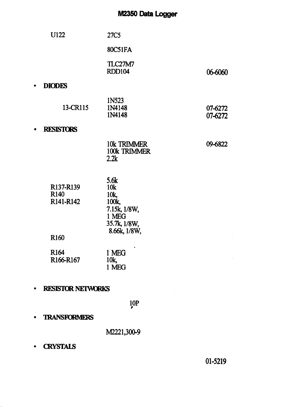
u122
U123
U124
U125
U126
U128
27C5
12
CDM6264
8OC5lFA
LM331
TLc27M7
RDD104
06-6264
06-6098
06-6236
06-6156
06-6248
CR1 12
CR1
130CR115
CR162
R130
R131
R132
R133
R134
R135
R137-R139
R140
R141-R142
R143
R144
R148
R149
R160
R161
R164
R166-R167
R170
R176
lN523 1
lN4148
lN4148
1OkTRIMMER
lOOkTRIMMER
2.2k
470k
220k
5.6k
1Ok
lOk,
1%
look,
1%
7.15k, 1/8W,
1MEG
35.7k, l/SW,
8&k,
220k
150k
1MFG lOk,
1%
1MEG
220k
1%
1%
l/SW,
1%
07-6261
07-6272
07-6272
0943322
09-6823
lo-7012
lo-7026
lo-7066
lo-7042
lo-7016
12-7540
12-7557
12-7620
lo-7028
12-7640
12-7623
m-7066
10-7024
10-7028
12-7540
10-7028
lo-7066
RN151
T157
Y158
Y159
22k SIP
M2221,300-9
MICRG32.768 KHZ
6.144 MHZ
1,OP
,
page 43
12-7566
4275-074
01-5219
01-5212
Page 49

J15
RIBBON-POST STRIP 40P
13-8007
BOARD
Cl-C3
c4
c5
a-cs
c9
Cl0
Cl1
Cl2
Cl3
Cl4
Cl5
Cl6
Cl7
C18-Cl9
C2O-C21
a2
c23
c24
c!25
c26
z
a9
c30
C31
C32
c33
c34
C35-C36
C37-C38
c39
Assembled Amp/P.S. Board
O.O056j.& 3kV,
O.l/AF, lOOV,
O.OOlS~, 3kV,
O.O056j~F, 3V, C
lOOpF, 3kV,
lo@, 2OV,
47pF, lOOV,
lOOpF, lOOV,
O.Ol@, lOOV,
47pF, lOOV,
lOO@, lOV,
lOpF, lOOV,
47pF, lOOV,
0.0056@, 3kV,
33pF, lOOV,
O.Ol)LF, lOOV,
O.l/AF, lOOV,
0.0056@, 3kV,
22&F, lsv,
220@, lOV,
O.O056pF, 3kV,
lOOpF, 3kV,
O.Ol@, lOOV,
lOO@, lOV,
lOOpF, lOOV,
0.0015@, 3kV, p
33pF, lOOV,
l@,
35V, DT
O.OOl/.lF, lgOV,
O.OOlS@, 3kV,
lop, 2OV,
O.lpF, lOOV,
33pF, lOOV,
o.oQlF, lOOV,
C
c
C
C
DT
C
C
c
C
DT
C
C
C
C
c
c
C
DT
DT
C
C
c
DT
C
C
c
C
DT
C
C
c
5371-002
04-5522
04-5521
04-5518
04-5522
04-5532
045592
04-5533
04-5527
04-5523
04-5533
04-5576
04-5573
04-5533
04-5522
i
04-5616
04-5523
04-5521
04-5522
04-5579
04-5639
04-5522
M-5532
04-5523
04-5576
04-5527
04-5518
04-5616
04-5575
04-5519
04-5518
04-5592
04-5519
04-5616
04-5523
page 44
Page 50
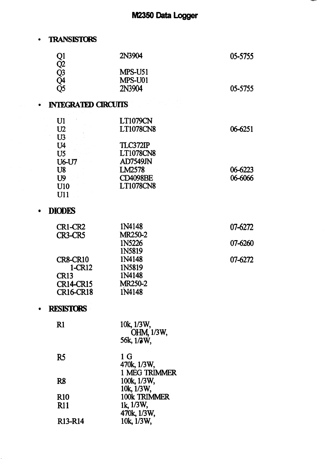
Ql
$
44
Q5
2N3904
MPS6534
IMPS-us1
MPS-UOl
2N3904
05-5755
05-5763
05-5765
05-5778
05-5755
CM-CR2
cR3-cR.5
CR6
CR7
CR8-CRlO
CR1
l-CR12
CR13
cRl4-CR15
CRl6-CR18
LT1079CN
LT1078CN8
CA3096
TLC372IP
LT1078CN8
AD7549JN
LM2578
CD4098BE
LT1078CN8
LM385Z2.5
lN4148
MR250-2 07-6266
lN5226
lN5819
lN4148
lN5819
lN4148
MR250-2 07-6266
lhJ4148
06-6252
M251
06-6023
06-6265
06-6251
06-6253
06-6223
06-6251
05-5791
07-6272
07-6260
07-6306
07-6272
07-6306
07-6272
07-6272
lOk,
Rl
R2
R3 56k, l&W,
R4
R5
R6
R7
R8
R9
RlO
Rll
R12
R&R14
mw, 5%
47
OHlq 1/3w,
4.7 MEG lo-7030
1G
47ok, 1/3w,
1MEGTRlMMER 09-6828
look, 1/3w,
lOk, 1/3w,
lOOkTRIMMER 09-6823
lk, 1/3w,
47ok,
lOk, 1/3w,
5%
mw, 5%
page 45
5%
5%
5%
5%
5%
5%
12-7748
12-7756
12-7789
12-7686
12-7757
12-7747
12-7748
12-7750
12-7757
12-7748
Page 51

R15
R16
R17-R19
R21
R22
R23
R24
R25
R26
R27
R28
R29
R30
R31
R32
R33-R36
R37
R38
R39-R40
R41
R42
R43
R44
R45
R46
R47
R48
R49
R50
R51
R52
R53
R54
R55
R56
R57
R58
R59
lk, 1/3w,
4.R mw,
lOk, 1/3W,S%
0.1
80*6k, 1/3w,
1 MEG,
10
lOk, 1/3w,
80.6k, 1/3w,
62k, 1/3W,
1 MEG, 1/3w, 1%
33.2k, 1/3W,
4% 1/3w,
100
221k, 1/3w,
lOk, 1/3w,
820 OHM,
lOk, 1/3w,
1MEG
look, 1/3w,
3k, 1/3w,
47ok, 1/3w,
1G
look, 1/3w,
lOk, 1/3w,
33.2k, 1/3W,
1 MEG, 1/3w, 1%
12k, 1/3w,
lk TRIMER
330 OHM, l/3W, 5%
1MEGTRIMMER
22k, 1/3w,
lOk, 1/3w,
lk, 1/3w,
1 MEG, 1/3w, 1%
80.6k, 1/3W,
1 MEG, 1/3w, 5%
lOk, 1/3w,
5%
5%
ohm,
3w, 1%
1%
1/3W,
MEG, 1/3w,
5%
1%
5%
1%
5%
om 1/3w,
1%
5%
1/3W,
1%
5%
5%
5%
5%
5%
1%
5%
5%
5%
5%
1%
5%,
1%
5%
5%
1%
\
12-7750
12-7755
12-7748
12-7647
12-7762
12-7763
12-7749
12-7748
12-7762
12-7790
12-7763
12-7793
12-7758
12-7746
12-7792
12-7748
12-7791
12-7764
lo-7028
12-7747
12-7768
12-7757
12-7686
12-7747
12-7748
12-7793
12-7763
12-7787
09-6831
12-7788
09-6828
12-7754
12-7748
12-7750
12-7763
12-7762
12-7751
12-7748
RN1
RN20
220k SIP 6P 12-7685
220k SIP
1OP
page 46
12-7578
Page 52

Tl
12
MI222 1;2300;4
M2350 LVPS
HVPS
4275-037
4275-089
l
DIODE4
CLOVERLEAF RECEPTACLES-01 l-6809-000
SPACXR-423-175
JACK SCREW 3/16 4750-l
BOARD
Assembled Backplane Board
lN4148
CR7 lN5819
lk
18-8771
18-8992
18-9019
5371-003
07-6272
076306
lo-7009
51-52
P3
P4
CONN-3ZA22DRSN
CONN-l-102866-0
CONN-640456-5 MTAlOO
P5 CONN-1-640456-O MTAlOO
P6
CONN-640456-2 MTAlOO
PlO CONN-640456-8 MTAlOO
Pll
CONN-640456-6 MT’AlOO
YOIIIt&ceBoard,~371x5
BOARD
I/OIIGfiUXBoard
27pF, lOOV,
o.o47pF, looV,
loopF, looV,
lo@?, 2ov,
C
c
c
DT
13-8181
13-8368
13-8057
13-8066
13-8073
13-8039
13-8095
5371-005
M-5614
04-5565
04-5576
04-5592
page 47
Page 53

.
l.IbiNsIsm
Cl2
4.7pF, lOV,
DT
04-5578
423
l
INTIm3AlEDmcIJrIs
u13
u14
u15
l DIODE3
cR26-CR28
.
mIsmRs
R16
R19
R20-R21
R30
l
I3ImcmRw
2N3904
MAX232EPE
87C257-200V10
P8OC51FA
lN523 1
33 OHM
8.2k
3.3k
10 OHM
05-5755
06-6188
06-6278
06-6236
07-6261
lo-7001
m-7015
m-7013
lo-7046
RN33‘
.
TIRANs-
Tl
l CRYSTW
Y25
0-s
P6
P7
P8
P9
1Ok
SIP 6P
M235oEL
12-7777
4275-090
’
6.144
MHZ
CONN-640457-2
MTAlOO 13-8147
coNw64o457-o
01-5212
13-8168
CONN-DD15F3S6OOX 13-8198
CONN-64@457-4*
Ibf’IAlOO
13-8089
,
page48
Page 54

Wdng
l AUDIO
Diagraq, Drawing
371 x 4
DSl
l -
53
54
J5
56
57
J9
JlO
Jll
312
513
514
Sl 71OLSyZQE
s2
*
s3 30-l-PB GRAYHILJL
s4
UNIMORPH 60690
RIBBON-OSO-020-455
C0NN-64044~5
WA100
2OP
CONN-l-640442-0 MTAlOO
coNNd40440-2
CONN-l-640442-0 MTAlOO
CONN-6404424 bITAl
CONN-640442-8
CONN-640442-6
MTAlOO
MTAlOO
RECPT-UG706iU “C”
CONN-AUDIO
61HA5F
RIBBON-050-020-455 20P
MRS
l-10
KNOB 50-lWD-1G
TOGGLE MTA 206 PA
21-9251
13-8025
13-8041
13-8136
13-8202
13-8136
13-8170
13-8184
13-8171
13-775 1
13-8385
13-8025
08-6511
08-6513
08-6612
08-6517
08-6657
Bl-B4
l IL3YImmm
Rl
R2
*
*
*
*
,
BATIERY-DURACELL
1OOk
NON-LOCKING
-“D”
KNOB-SO-1-1G
lk
t
I&350 HANDLE
M2350 CAN
ASSY.
M2221 BATTERY HARNESS
M2350 MAIN
HARNESS
M2350 RIBBON HARNESS
M2350 FRONT PANEL
page 49
21-9313
09-6756
08-6605
lo-7009
7371-011
4371-029
8261-089
8371-019
8371-020
9371-012
Page 55
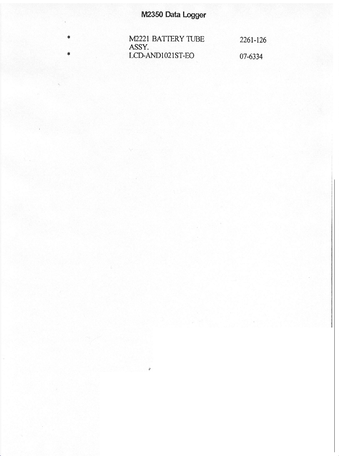
page 50
Page 56

DRAWINGS AND DIAGRAMS
1
CentralI’rocewBoard,DrawingNo.371xl
Central Processor Board Component Layout, Drawing No. 371 x 27
Amplifier/Power Supply Ebard, Drawing No. 371 x 2
Amplifier/Powzr Supply Board Component Layout, Drawing No. 371 x 24
-Ekkplane
Backplane Board Component Layout, Drawing 371 x 29
I/O Interface Board, Drawing No. 371 x
I/O
Intim
Wiring Diagram, Drawing No. 371 x 4
Bo&,
Drawing No. 371 x 3
5
Ebard Component Layout, Drawing No. 371 x 30
Page 57

nm“
CPI‘E
‘w,*
l-J
/h
Page 58
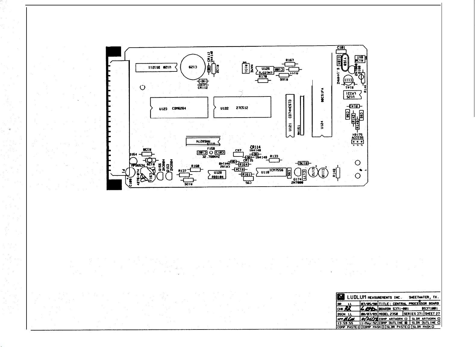
r
nra
CR1 14
Page 59
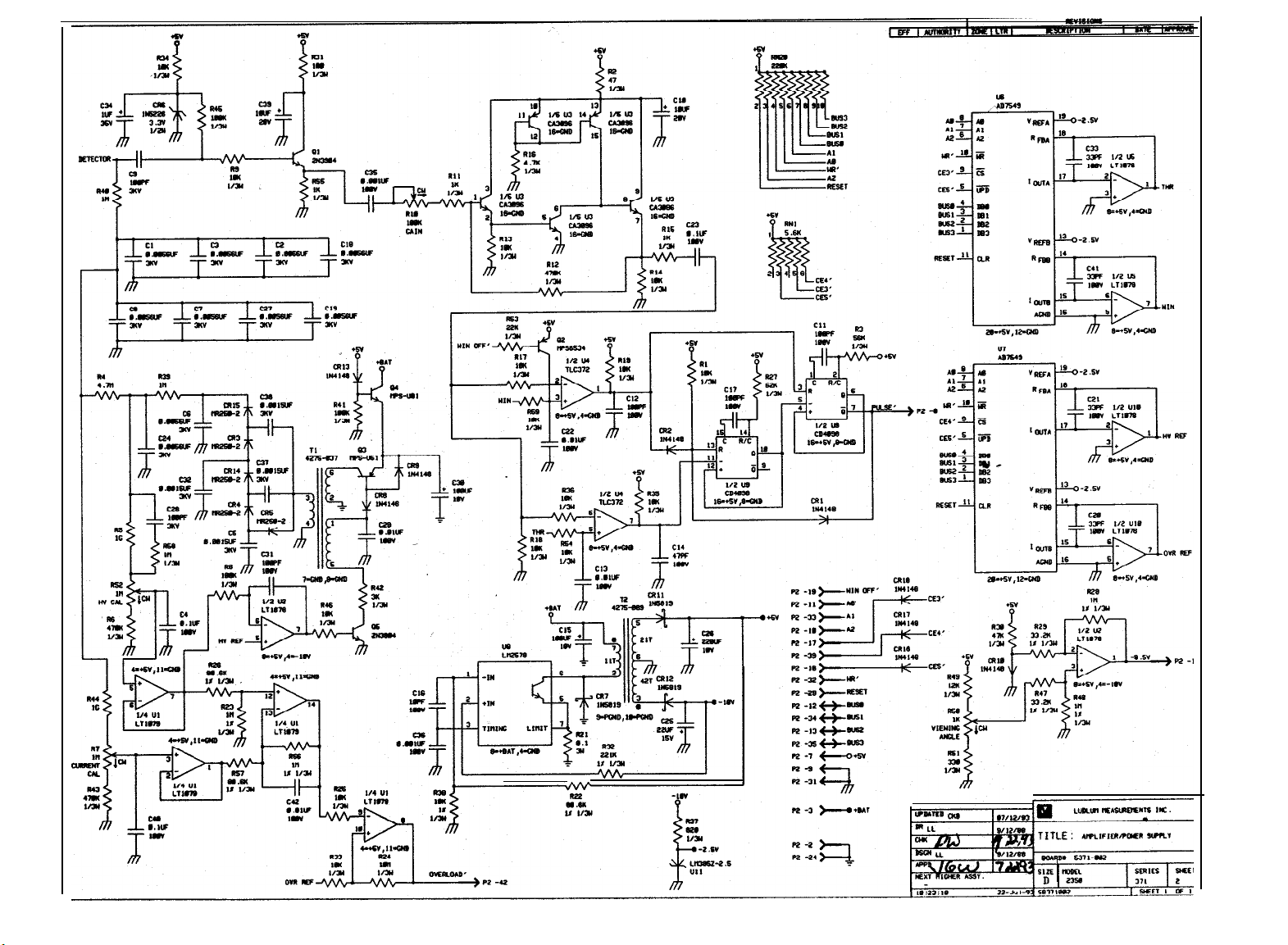
Page 60

Page 61

.
I
VYIO-
I I
e
--
Ilc.
Page 62
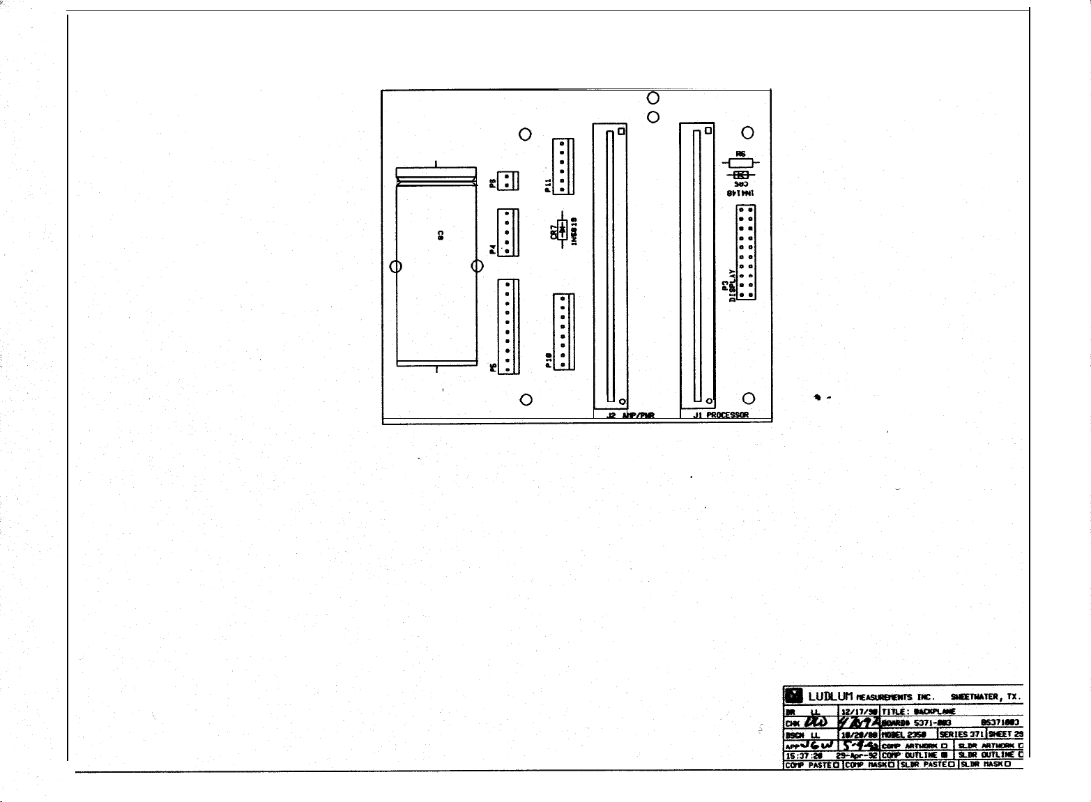
Page 63

“-a
”
Pa-4
n-r
n
“3
“-4
n
“-#
-3
-1
-a
Page 64
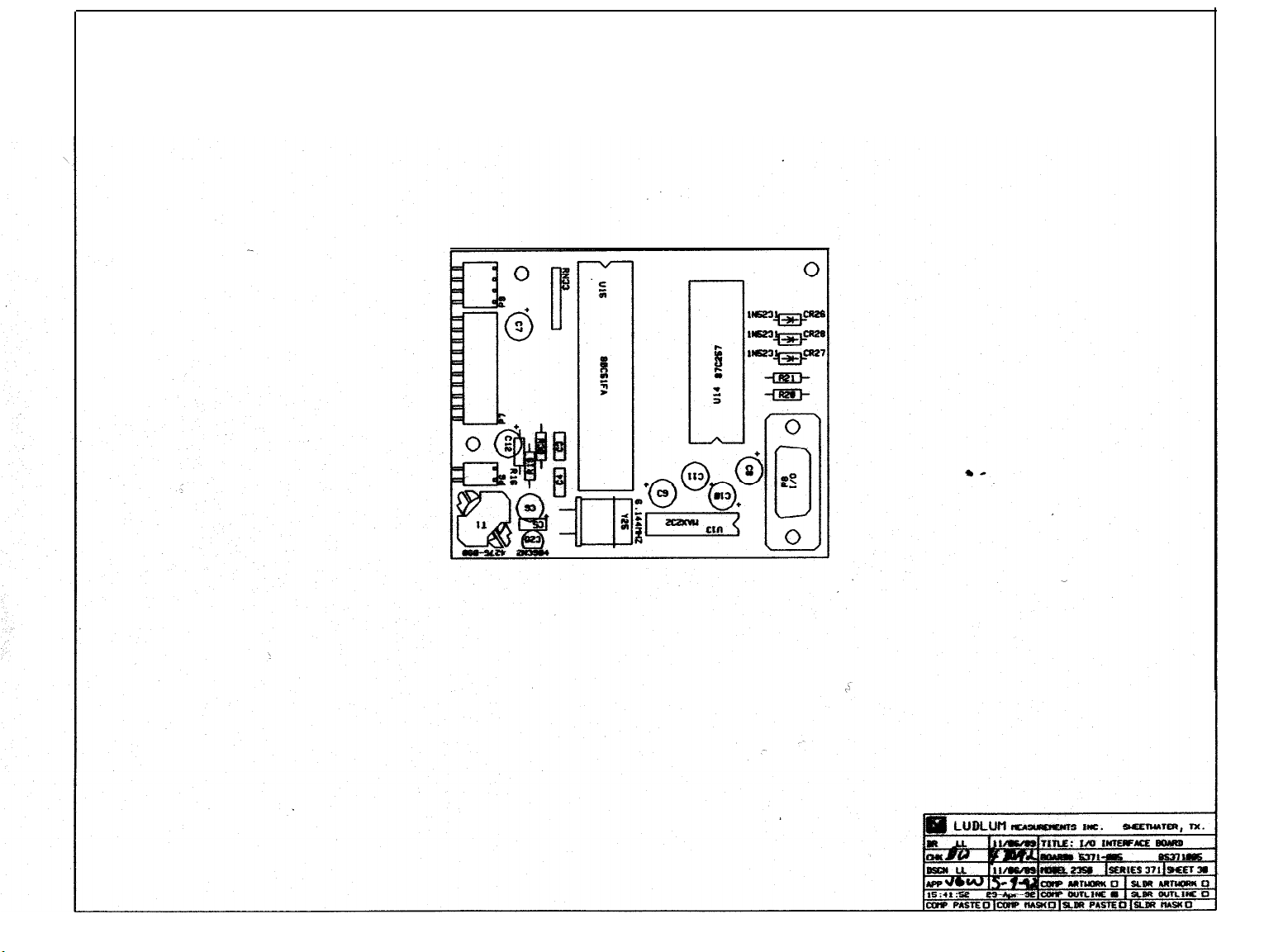
Page 65

 Loading...