


LUDLUM MODEL 2241-2
SURVEY METER
January 2016
Serial Number 237627 and Succeeding
Serial Numbers

LUDLUM MODEL 2241-2
SURVEY METER
January 2016
Serial Number 237627 and Succeeding
Serial Numbers

STATEMENT OF WARRANTY
Ludlum Measurements, Inc. warrants the products covered in this manual to be free of
defects due to workmanship, material, and design for a period of twelve months from the
date of delivery. The calibration of a product is warranted to be within its specified
accuracy limits at the time of shipment. In the event of instrument failure, notify Ludlum
Measurements to determine if repair, recalibration, or replacement is required.
This warranty excludes the replacement of photomultiplier tubes, G-M and proportional
tubes, and scintillation crystals which are broken due to excessive physical abuse or used
for purposes other than intended.
There are no warranties, express or implied, including without limitation any implied
warranty of merchantability or fitness, which extend beyond the description of the face
there of. If the product does not perform as warranted herein, purchaser’s sole remedy
shall be repair or replacement, at the option of Ludlum Measurements. In no event will
Ludlum Measurements be liable for damages, lost revenue, lost wages, or any other
incidental or consequential damages, arising from the purchase, use, or inability to
product
.
use
RETURN OF GOODS TO MANUFACTURER
If equipment needs to be returned to Ludlum Measurements, Inc. for repair or calibration, please send to
the address below. All shipments should include documentation containing return shipping address,
customer name, telephone number, description of service requested, and all other necessary information.
Your cooperation will expedite the return of your equipment.
ATTN: REPAIR DEPARTMENT
501 OAK STREET
SWEETWATER, TX 79556
LUDLUM MEASUREMENTS, INC.
800-622-0828 325-235-5494
FAX 325-235-4672


Table of Contents
Introduction 1
Getting Started 2
Unpacking and Repacking 2-1
Battery Installation 2-1
Operational Check 2-2
Specifications 3
Instrument 3-1
Removable Switchboard Adjustable Parameters 3-2
Identification of Controls and Functions 4
Display 4-1
Display Status Definitions 4-1
Front-Panel Controls 4-2
Front-Panel Calibration Controls 4-3
Main Board Controls 4-4
Switch Board Controls 4-5
Safety Considerations 5
Environmental Conditions for Normal Use 5-1
Detector Connector 5-1
Warning Markings and Symbols 5-1
Maintenance 6
Recalibration 6-1
Batteries 6-2
Technical Theory of Operation 7
Main Board 7-1
Switch Board 7-3
Display Board 7-3
Instrument Setup 8
Entering or Changing Switch Board Parameters 8-1
Ludlum Measurements, Inc. January 2016

Model 2241-2 Technical Manual
The Function Switch 8-1
Function Switch Position Descriptions and Variables 8-2
Loading Default Parameters 8-6
Calibration 8-7
General Detector Setup Information 8-8
Counts per minute (C/m) Calibration 8-9
R/hr Calibration 8-11
Determining CC and DTC 8-12
Detector Overload (OVL) Calibration 8-19
Software License Agreement 8-21
Recycling 9
Parts List 10
Model 2241-2 Survey Meter 10-1
Main Circuit Board, Drawing 408 × 223 10-1
Calibration Board, Drawing 408 × 127 10-3
Display Board, Drawing 408 × 259 10-4
Switch Board, Drawing 408 × 45 10-5
Chassis Wiring Diagram, Drawing 408 × 131 10-5
Drawings and Diagrams 11
RS-232 Output Formats - Appendix A A
Binary Output Format A-1
ASCII Output Format A-4
Ludlum Measurements, Inc. January 2016

Model 2241-2 Technical Manual
Section
Section 1
1
Introduction
he Model 2241-2 is a portable microprocessor-based digital scaler/
ratemeter designed for use with scintillation, Geiger-Mueller
T
mode) Liquid Crystal Display (LCD) with moving decimal point. A three
position switch labeled ˝
operating mode for the instrument. A locking toggle switch labeled ˝
and
out detectors.
Programmable display units (
either R/hr, Sv/h, cpm, or cps with multipliers of micro (µ) or milli (m) for
R/hr and Sv/h and kilo (k) for cpm or cps. The display units are autoranging, enabling the readout to display a broad range of radiation levels.
The display also offers lower limit capability. For example, the display can be
set to show only values that are greater than or equal to1 µR/hr.
(GM), and proportional type detectors to measure ionizing
radiation. Data is presented on a four-digit (six digits in the scaler
OFF/RATEMETER/SCALER
DET
2˝ allows for quick change of operating parameters when changing
RATEMETER
mode only) are represented in
˝ selects the desired
DET
1
This instrument incorporates independent adjustable alarms for
SCALER
and
indicators. The first-level alarm is indicated by display of the word ˝
on the LCD. The second-level alarm is indicated by display of the word
˝
ALARM
alarm condition will also display the word ˝
audible tone. Both audible alarms may be silenced (acknowledged) by
depressing the
Other features include Dead Time Correction (DTC) to compensate for
detector dead time; audible click-per-event with programmable 1, 10, 100,
and 1000 divide-by; LCD backlight with programmable ON time;
programmable fixed or variable response time; and count overflow visual
alarm, indicating that the counting circuitry is nearing the maximum
counting capability.
Ludlum Measurements, Inc. Page 1-1 January 2016
operating modes. The
˝ and by the emitting of a continuous audible tone. The
RESET
switch. All alarms are concurrent.
RATEMETER
ALARM
mode has two alarm
˝ and produce the same
RATEMETER
ALERT
SCALER
˝

Model 2241-2 Technical Manual Section 1
All of the features described above may be programmed manually using the
internal switch board or by computer through the RS-232 port. Two
different detector operating parameters may be stored in non-volatile
memory. The switch board can be removed after entering or changing
parameters to prevent tampering with setup parameters.
A regulated high-voltage power supply and two independent set-point
controls adjustable from 400 to 2400 volts with detector overload detection
and adjustable discrimination levels add versatility to the instrument. This
supports operation for a broad range of detectors and connecting cable
lengths. All of the calibration controls are covered to prevent any inadvertent
adjustment to the detector operating parameters.
The instrument is powered by two standard ˝D˝ cell batteries. The unit body
is made of cast-and-drawn aluminum with beige powder coating, which aids
in the decontamination of surfaces.
Ludlum Measurements, Inc. Page 1-2 January 2016

Model 2241-2 Technical Manual Section 2
Section
2
Getting Started
Unpacking and R epacking
Remove the calibration certificates and place them in a secure location.
Remove the instrument, detectors, and accessories (batteries, cable, etc.), and
ensure that all of the items listed on the packing list are in the carton. Check
individual item serial numbers and ensure calibration certificates match. The
Model 2241-2 serial number is located on the front panel below the battery
compartment. Most Ludlum Measurements, Inc. detectors have a label on
the base or body of the detector for model and serial number identification.
Important!
If multiple shipments are received, ensure that the detectors
and instruments are not interchanged. Each instrument is
calibrated to specific detectors, and are therefore, not
interchangeable.
To return an instrument for repair or calibration, provide sufficient packing
material to prevent damage during shipment. Also, provide appropriate
warning labels to ensure careful handling. Include detector(s) and related
cable(s) for calibration.
Every instrument must be accompanied by an Instrument Return Form,
which can be downloaded from the Ludlum website at www.ludlums.com.
Find the form by clicking the “Support” tab and selecting “Repair and
Calibration” from the drop-down menu. Then choose the appropriate
Repair and Calibration division where you will find a link to the form.
Battery Installation
Ensure the OFF/SCALER/RATEMETER switch is in the OFF position. Open
the battery lid by turning the quarter-turn thumb screw counterclockwise
Ludlum Measurements, Inc. Page 2-1 January 2016

Model 2241-2 Technical Manual
Install two ˝D˝ size batteries in the compartment. Note the (+) and (–)
marks inside the battery door. Match the battery polarity to these marks.
Close the battery box lid.
Note:
The center post of a “D” size battery is positive.
Operational Check
Connect a detector to the Model 2241-2 by using the cable provided; firmly
pushing the connectors together while twisting clockwise until the
connector latches (one quarter-turn). The diagram to the left illustrates how
this is done. Next, place the
position.
DETECTOR SELECTOR
Section 2
switch in the appropriate
Turn the
OFF/SCALER/RATEMETER
switch to the
RATEMETER
position.
Notice that the display goes through an initialization sequence. The display
will show all 8s with decimal points. Check to make sure all segments
display, as illustrated in the diagram to the left.
The LCD then displays the firmware number in the format
“P-XX YY.” The “XX” is the firmware number, and the “YY”
is the firmware version. (The figure to the left is for example only;
to illustrate location of display.)
The minimum displayable value (00.0 µR/hr, for example) should
be shown. When switched to the
SCALER
position, a single 0 will
be displayed.
The display will auto-range to the current level (see figure at left). When
auto-ranging down, the Model 2241-2 uses multiples of 5. This technique
keeps the decimal point from jumping between numbers when
viewing values around multiples of 10.
Check for a proper background reading:
If using a Ludlum Model 44-9 detector, a typical
reading would be 25-50 cpm or 8-15 µR/hr.
A reference reading (or readings) with a check source should be obtained
with the detector(s) in a constant and reproducible manner at the time of
Ludlum Measurements, Inc. Page 2-2 January 2016
If using a Ludlum Model 44-2 detector, a typical reading
would be 1.4-2.6 kcpm or 8-15 µR/hr.

Model 2241-2 Technical Manual Section 2
calibration or at the time the instrument is received in the field.
If at any time the instrument fails to read within 20% of the reference
reading when using the same check source, it should be sent to a calibration
facility for recalibration and/or repair. If desired, multiple readings may be
taken at different distances and/or with different sources so that other
ranges or scales are checked.
Switch the AUD ON/OFF switch to the ON position and confirm the external
unimorph speaker produces an audible click for each event detected (audio
divide-by 1 parameter). The AUD ON/OFF switch will silence the clicks if in
the OFF position; however, an audible alarm condition will still be heard.
Increase the source activity or lower the alert and alarm points to initiate an
ALERT and ALARM condition. (Refer to Section 8, “Entering or Changing
Switchboard Parameters.”) Depress the RESET switch to acknowledge the
audible alarm. Decrease the radiation activity below the ALERT and ALARM
threshold, and depress the RESET switch to clear the alarm conditions. If an
alarm condition is not present, depressing the RESET switch the first time will
reset the alert condition and zero the ratemeter.
Position a check source to produce a ratemeter reading of 100 to 2000
counts/minute or 10-100 µR/hr. While observing the ratemeter fluctuations,
select between the fast and slow response time (F/S) positions to observe
variations in the display. The S position should respond approximately five
times slower than the F position (for fixed response mode) and three times
slower when in variable response mode. The slow response position is
normally used when the Model 2241-2 is displaying low numbers, which
require a more stable display. The fast response position is used at high
count levels.
Move the
OFF/SCALER/RATEMETER switch to the SCALER position. Depress
the COUNT switch located in the end of the carrying handle in order to
initiate a count cycle. The word “COUNTING” should be flashing on the
LCD during the count cycle and should disappear at the end of the
predetermined count time. If a scaler ALARM condition occurs, the RESET
switch can be depressed to acknowledge the alarm; however, the COUNT
switch must be depressed to clear the visual ALARM and to restart the count
cycle.
Depress and release the LIGHT switch. The backlight located behind the
LCD should illuminate (for pre-programmed ON time). Select the desired
F/S, AUD ON/OFF, and RATEMETER or SCALER parameters and proceed to
use the instrument.
Ludlum Measurements, Inc. Page 2-3 January 2016

Model 2241-2 Technical Manual Section 3
Section
3
Instrument:
Specifications
Power: two each, ˝D˝ cell batteries housed in an externally accessible sealed
compartment. Current draw is approximately 35 mA with the backlight OFF.
Minimum battery voltage is 2.2 ±0.1 Vdc.
Battery Dependence: Meter readings vary by less than 3% from fully
charged batteries until the battery symbol appears, indicating the need for
recharge or replacement.
Battery Life: typically 200 hours with alkaline batteries (display indicates low-
battery condition). Instrument will operate for approximately 24 hours after
the battery symbol first appears.
Warm-up Time: Unit may be used immediately after the LCD initialization
sequence is completed (approximately 5 seconds after power-up).
Linearity: Readings are within 10% of true value with a detector connected.
Display: a four-digit Liquid Crystal Display (LCD) with digits 1.3 cm (0.5 in.)
in height. Two additional 0.5 cm (0.2 in.) digits are used for the overflow
counter (SCALER mode) and exponential powers (parameter setup).
Enunciators are provided for display units,
detector OVERLOAD, counting OVERFLOW, and scaler COUNTING.
RATEMETER: Depending upon how the instrument was calibrated, the
RATEMETER can display in either R/hr, Sv/h, cpm, or cps when the control
switch is in the RATEMETER position.
SCALER: activated by pushbutton in handle when the three-position switch
is in the SCALER position. Count time is adjustable.
ALERT, ALARM, low-battery,
Ludlum Measurements, Inc. Page 3-1 January 2016

Model 2241-2 Technical Manual Section 3
Calibration Controls: accessible from the front of the instrument (protective
cover provided). These controls are preset at the factory or calibration lab
and should not be adjusted by field personnel.
Discriminator / Input Sensitivity: adjustable from 2 to 100 mV;
negative pulse response
Overload: indicated by OVERLOAD on the display; adjustable
depending on the detector selected
High Voltage: two independent controls, each adjustable from 400-
2400 volts. Two separate set points for DET1 and DET2 are
regulated within 0.2% at 1000 Vdc, maximum load of 50 µA.
RESET: a pushbutton for zeroing the display, acknowledging and/or
resetting the alarm
Alert/Alarm: indicated by either an ALERT or ALARM enunciator on the
display (RATEMETER mode only) and by an audible tone
Note:
The RESET button only silences the alarm in the current mode
that the instrument is in. For example, the RESET button will
not affect the scaler alarm if the instrument is in the ratemeter
mode.
Audio: built-in audio speaker (unimorph) with AUD ON/OFF switch; greater
than 60 dB at 2 feet
LIGHT: display backlight activated by pushbutton
Temperature Range: -20 to 50 °C (-4 to 122 °F)
Size: 16.5 x 8.9x 21.6 cm (6.5 x 3.5 x 8.5 in.) (H x W x L)
Weight: 1.6 kg (3.5 lb), including batteries
Removable
Switchboard
Adjustable
Parameters:
Backlight ˝ON˝ Time: 5, 15, 30, 60, 90, 120, 180, or 240 seconds for the
backlight to stay on when activated by the pushbutton; factory set at 5
Set Minimum Display: allows lower limit of the auto-ranging display to be
fixed. For example, the display can be set to only show values above or equal
to 1 µR/hr.
RS-232 Data Dump Mode: enables or disables dump mode to the RS-232
port (˝D˝ type connector). When enabled, the data will be dumped every two
seconds.
RS-232 Detector Setup Mode: allows for input of detector parameters via
the RS-232 port
Ludlum Measurements, Inc. Page 3-2 January 2016

Model 2241-2 Technical Manual Section 3
Baud Rate: selects either 150, 300, 600, 1200, 2400, 4800, 9600, or 19200 bps
Detector Dead Time Compensation (DTC)
: adjustable from 0 to 9999
microseconds
Calibration Constant: adjustable from 0.001 to 280 × 10
9
counts/display
unit
Display Units: can display in R/hr, Sv/h, cpm, or cps.
Display Range: auto-ranging from 0.0 µR/hr – 9999 R/hr; 0.000 µSv/h –
9999 Sv/h; 0 cpm – 999k cpm; or 0 cps – 100 kcps.
Time Base: can display in seconds or minutes
Audio Divide: 1, 10, 100, or 1000 events per click
Response Time: variable or fixed ratemeter response (All stated times
correspond to a range of 10% to 90% of the final reading). Factory default is
variable so that the instrument will automatically adjust the response time to
the best setting for the current count rate.
Variable Response: dependent on the number of counts present,
typically 4 to 25 seconds for FAST, and 4 to 60 seconds for SLOW
Fixed Response: The parameter is adjustable from 1 to 25,
resulting in a FAST response from approximately 2 to 50 seconds.
The SLOW response is approximately 10 to 250 seconds. For MDAtype measurements, the fixed response mode is recommended.
Ratemeter Alert/Alarm: set at any point corresponding to the pre-selected
ratemeter range
Scaler Alarm: adjustable from 1 to 9999 counts
Scaler Count Time: Adjustable from 1 to 9999 seconds.
Ludlum Measurements, Inc. Page 3-3 January 2016

Model 2241-2 Technical Manual Section 4
Section
Identification of Controls and
4
Functions
Display
The Model 2241-2 utilizes a four-digit liquid crystal display (LCD) with two-
digit overflow (SCALER mode) and moving decimal point. The two
smaller digits located in the lower right corner of the display indicate
counter OVERFLOW when in the scaler counting mode (equivalent to a
six-digit scaler) or exponential power when in the parameter setup
mode. The upper right corner of the LCD displays units and
multiplier(s) - R/hr, mR/hr, or µR/hr; Sv/h, mSv/h, or µSv/h; C/m,
kC/m, C/s, or kC/s. The bottom part of the readout displays the
ALARM, ALERT, OFLOW, OVERLOAD annunciators and the low-battery icon.
COUNTING indicates that the scaler mode has been initiated and is in the
counting process.
Display Status Definitions
ALARM: Ratemeter or scaler count has increased above the preset alarm
threshold. An audible continuous tone will accompany the ˝latching˝ ALARM
condition. Depressing RESET will acknowledge the audible ratemeter and/or
scaler alarm. Depressing RESET a second time will reset the ratemeter
reading and ratemeter alarm. To reset the scaler
switch located in the carrying handle to re-initiate the scaler count cycle.
ALARM, depress the COUNT
ALERT: Ratemeter count has increased above the preset alert threshold. To
reset an ALERT condition, press RESET once if in the non-alarm condition
and twice if in an alarm condition. (The first depression in the alarm
condition acknowledges the audible alarm.) The ratemeter will reset to the
minimum displayable reading each time the alert is reset.
OFLOW (Overflow): In RATEMETER mode, this indicates that the incoming
count exceeds the capability to display stable or reliable readings
corresponding to the radiation level being measured. The overflow symbol
will appear when the ratemeter exceeds 100 kcps or if the dead time
correction is greater than 75%.
Ludlum Measurements, Inc. Page 4-1 January 2016
OFLOW will appear in the SCALER

Model 2241-2 Technical Manual Section 4
mode when the six-digit display (four digits display and two overflow digits
in right corner) reaches 999999 and starts to roll over again.
OVERLOAD: indicates that the detector is being exposed to radiation
intensities greater than the detector maximum operating limit. For alpha
and/or beta type scintillation detectors, an OVERLOAD may indicate that the
detector face has been punctured allowing external light to saturate the
photomultiplier tube inside the detector. The overload alarm point is set by
adjusting the OVL control located underneath the calibration cover.
Low-battery icon: indicates that the batteries have decreased to the
minimum operating voltage of 2.2 ±0.1 Vdc. Instrument will continue to
operate for approximately 24 hours thereafter.
COUNTING: Indicates that the scaler COUNT switch has been depressed and
that the scaler is accumulating counts for the pre-determined count time.
Front-Panel Controls
DET1/DET2 (Detector Select) Switch: a protected (locking) toggle switch
used to select between DET1 and DET2 parameters. The switch can be
pulled up and then over to the desired selection.
OFF/RATEMETER/SCALER Switch: a three-position rotary switch that
applies power to the instrument and selects RATEMETER or SCALER
counting mode
AUD ON/OFF Switch: The clicks-per-event audio may be silenced or
enabled via this front-panel toggle switch. The audible alarm is independent
of the AUD ON/OFF switch and will override the audible clicks-per-event.
An audible alarm can only be silenced by depressing the RESET button.
F/S (Fast/Slow) Response Switch: a two-position toggle switch that selects
fast or slow counting response time
Ludlum Measurements, Inc. Page 4-2 January 2016

Model 2241-2 Technical Manual Section 4
Variable Response: The F position allows the time constant (TC) to vary
from 1 to 10 seconds, while the
response time is automatically adjusted in proportion to the incoming count
rate between the
Fixed Response: The F position corresponds to the selected fixed response
F/S TC variables.
time - TC. The S position is five times slower than the selected fast TC.
LIGHT (LCD Backlight): A pushbutton switch, when depressed, illuminates
the LCD for a pre-programmed time. The backlight ON time can be
selected between 5 and 240 seconds during the parameter setup.
RESET Pushbutton Switch: In the non-alarm condition, depressing the
RESET switch resets the ratemeter display to the minimum display readout.
In an alarm condition (ratemeter or scaler), depressing RESET will silence the
audible alarm. Depressing RESET a second time will reset the ratemeter
alarm and/or alert condition.
Note:
S position varies from 1 to 30 seconds. The
The RESET button only silences the alarm in the current mode
that the instrument is in. For example, the RESET button will
not affect the scaler alarm if the instrument is in the ratemeter
mode.
Scaler COUNT Switch: pushbutton switch located in the end of the Model
2241-2 carrying handle, which when depressed, initializes the start of the
scaler count accumulation for the preset scaling time. The
SCALER/RATEMETER switch must be in the SCALER position to initiate the
counting cycle. The scaler display uses the two digits in the lower right hand
corner for the two most significant digits of the six-digit readout. Scaling
time can be set from 1 to 9999 seconds in the parameter setup by way of the
switch board. Depressing the
COUNT switch after a scaler ALARM will reset
the scaler display to 0, resetting the alarm condition.
Front Panel Calibration Controls
Note:
Remove the front-panel calibration cover to expose the
following calibration controls:
Ludlum Measurements, Inc. Page 4-3 January 2016

Model 2241-2 Technical Manual Section 4
DISC 1 and DISC 2 (Discriminator 1 and 2): Two independent multi-turn
potentiometers (approximately 20 revolutions) are used to vary the detector
pulse-counting threshold from 2 to 100 millivolts for DET1 and DET2
respectively. A Ludlum Model 500 Pulser or equivalent should be used in
checking or adjusting the pulse discrimination parameter.
Note:
When making adjustments to the HV potentiometers, make
note of the following precautions: Use a Ludlum Model 500
Pulser or high-impedance voltmeter with a high-voltage probe
to measure the high voltage at the detector connector. If a
Ludlum Model 500 Pulser is not available, ensure that the
impedance of voltmeter used is 1000 megohms or greater.
HV1, HV2: multi-turn potentiometers (approximately 20 revolutions) that
vary the detector voltage from 200 to 2500 volts. The maximum high
voltage output is adjusted by the HV LIMIT potentiometer located on the
internal main board.
OVL (Detector Overload): a multi-turn potentiometer (approximately 20
revolutions) adjusts the detector current level that must be exceeded to
initiate an OVERLOAD alarm. This control adjusts the current level
discrimination point from 0.5 and 40 microamperes, corresponding to the
specific detector saturation point.
Main Board Controls
Note:
To access the internal circuit boards, unlatch the latches at each
end of the Model 2241-2. Carefully separate the top chassis
from the bottom cover (referred to as a "can"). The can has the
audio speaker (unimorph) with a two-conductor cable attached
to the main board. The audio plug may be disconnected during
the internal control adjustments.
Ludlum Measurements, Inc. Page 4-4 January 2016

Model 2241-2 Technical Manual Section 4
HV LIMIT (R027): A multi-turn potentiometer (approximately 20
revolutions) sets the maximum HV limit with the front panel
HV control
adjusted to the maximum clockwise position. It is adjustable from 1250 to
2400 Vdc.
VOLUME (R002): A multi-turn potentiometer (approximately 20
revolutions) varies the audible click-per-event and alarm audio. Adjust the
control to the maximum clockwise position for maximum volume. If the
VOLUME control is adjusted to the maximum counterclockwise position, the
clicks-per-event or the audible alarm(s) will not be audible when active.
Switch Board Controls
The switch board utilizes a 16-position rotary switch (FUNCTION) to select
the 16 setup parameters. (Refer to schematics and component layout
drawing near the end of the manual.) All of the setup parameters are stored
in the non-volatile EEPROM, which will retain data even after the Model
2241-2 batteries are removed. After the parameters are entered, the switch
board can be removed and the Model 2241-2 will continue to operate from
the previously programmed information. Changing parameters and
information on switchboard controls are covered in detail in Section 8 of
this manual.
Ludlum Measurements, Inc. Page 4-5 January 2016

Model 2241-2 Technical Manual Section 5
Section
5
Safety Considerations
Environmental Conditions for Normal Use
Indoor or outdoor use
No maximum altitude
Temperature range of -20 to 50 °C (-4 to 122 °F)
Maximum relative humidity of less than 95% (non-condensing)
Pollution Degree 3 (as defined by IEC 664) (Occurs when conductive
pollution or dry nonconductive pollution becomes conductive due to
condensation. This is typical of industrial or construction sites.)
Detector Connector
Caution:
The detector operating voltage (HV) is supplied to the detector
by way of the input connector. A mild electric shock may occur
if contact is made with the center pin of the input connector.
Switch the Model 2241-2 to the OFF position before connecting
or disconnecting the cable or detector.
Warning Markings and Symbols
Ludlum Measurements, Inc. Page 5-1 January 2016
Caution!
The operator or responsible body is cautioned that the
protection provided by the equipment may be impaired if the
equipment is used in a manner not specified by Ludlum
Measurements, Inc.

Model 2241-2 Technical Manual
The Model 2241-2 Survey Meter is marked with
the following symbols:
CAUTION, RISK OF ELECTRIC SHOCK (per ISO 3864, No. B.3.6):
designates a terminal (connector) that allows connection to a voltage
exceeding 1 kV. Contact with the subject connector while the instrument is
on or shortly after turning off may result in electric shock. This symbol
appears on the front panel.
CAUTION (per ISO 3864, No. B.3.1): designates hazardous live voltage
and risk of electric shock. During normal use, internal components are
hazardous live. This instrument must be isolated or disconnected from the
hazardous live voltage before accessing the internal components. This
symbol appears on the front panel. Note the following precautions:
Warning!
The operator is strongly cautioned to take the following
precautions to avoid contact with internal hazardous live parts
that are accessible using a tool:
1. Turn the instrument power
2. Allow the instrument to sit for one minute before accessing
any internal components.
OFF
and remove the batteries.
Section 5
Caution!
Verify instrument voltage input rating before connecting to a
power converter. If the wrong power converter is used, the
instrument and/or power converter could be damaged.
The “crossed-out wheelie bin” symbol notifies the consumer that the
product is not to be mixed with unsorted municipal waste when discarding.
Each material must be separated. The symbol is placed on the battery
compartment. See Section 9, “Recycling,” for further information.
Ludlum Measurements, Inc. Page 5-2 January 2016

Model 2241-2 Technical Manual Section 6
Section
6
Maintenance
nstrument maintenance consists of keeping the instrument clean and
periodically checking the batteries and the calibration. The Model
2241-2 instrument may be externally cleaned with a damp cloth (using
I
only water as the wetting agent). Do not immerse the instrument in any
liquid. Observe the following precautions when cleaning:
1. Turn the instrument
2. Allow the instrument to sit for one minute before performing
any external cleaning or accessing internal components for
maintenance.
OFF and remove the batteries.
Recalibration
Recalibration should be accomplished after any maintenance or adjustment
of any kind has been performed on the instrument. Battery replacements are
not considered to be maintenance and do not normally require the
instrument to be recalibrated.
Note:
Ludlum Measurements, Inc. recommends recalibration at
intervals no greater than one year. Check the appropriate
regulations to determine required recalibration intervals.
Ludlum Measurements offers a full-service repair and calibration
department. We not only repair and calibrate our own instruments but most
other manufacturer’s instruments as well.
See Section 8, “Instrument Setup,” for further details on instrument
calibration.
Ludlum Measurements, Inc. Page 6-1 January 2016

Model 2241-2 Technical Manual Section 6
Batteries
The batteries should be removed and the battery contacts cleaned of any
corrosion at least every three months. If the instrument has been exposed to
a very dusty or corrosive atmosphere, more frequent battery servicing should
be used. Use a spanner wrench to unscrew the battery contact insulators,
exposing the internal contacts and battery springs. Removing the handle will
facilitate access to these contacts.
Note:
Never store the instrument over 30 days without removing the
batteries. Although this instrument will operate at very high
ambient temperatures, battery seal failure can occur at
temperatures as low as 37 °C (100 °F).
Ludlum Measurements, Inc. Page 6-2 January 2016

Model 2241-2 Technical Manual Section 7
Section
7
Refer to the Main
Board schematic
for the following:
T echnical Theory of Operation
Detector Input/Amplifier
Negative-going detector pulses are coupled from the detector through C021 to
amplifier U021. R024 and CR021 protect the input of U021 from inadvertent
shorts. Self-biased amplifier U021 provides gain in proportion to R022, divided
by R025. Transistor pins 4, 5, and 6 of U021, provide amplification. Pins 10-15
of U021 are coupled as a constant current source to pin 6 of U021. The output
is self-biased to 2 Vbe (approximately 1.4 volts) at pin 7 of U021. This provides
just enough bias current through pin 6 of U021 to conduct all of the current
from the constant current source. Positive pulses from pin 7 of U021 are
coupled to the discriminator (U011) through R031 and C012.
Discriminator
Positive pulses from amplifier U021 are coupled to pin 2 of U011 comparator.
The discrimination level is set by the DISC control connected to pin 3 of U011.
As the positive pulses at pin 2 of U011 increase above DISC reference at pin 3,
pin 1 goes low, producing a low pulse. Pin 1 of U011 is normally held high (+5
volts) by R014.
The low pulse from pin 1 of U021 is coupled to univibrator U001. U001
shapes and fixes the pulse width to approximately 10 µs. The univibrator is
configured in the non-retriggerable mode. Negative pulses from pin 9 of U001
are coupled to the µP for counting.
Low-V oltage Supply
Battery voltage is coupled to DC-DC converter U231. U231 and related
components provide +5 V to power the µP, op-amps, and logic circuitry.
R135 and R136 provide voltage division for low-battery detection. Pin 6 of
U231 provides a low signal when the battery voltage decreases to +2.2 ±0.1
Vdc. U121 provides the +2.5 Vdc reference for the
references.
Ludlum Measurements, Inc. Page 7-1 January 2016
HV and DISC control

Model 2241-2 Technical Manual Section 7
High-V oltage Supply
High Voltage is developed by blocking oscillator Q241, T141, and C244 and
rectified by voltage multiplier CR041-CR043, C041-C043, and C141. High
voltage increases as current through R241 increases, with maximum output
voltage with Q241 saturated. High voltage is coupled back through R034 to opamp pin 2 of U131. Resistor network R027, R132 completes the HV division
circuit to ground. R027 provides HV limit from 1250-2400 when the HV
control on the calibration board is at maximum. The regulated HV output is
controlled by the HV1 and HV2 potentiometers located under the CAL cover on
the front panel. This control provides the reference for comparator pin 3,
U131. During stable operation, the voltage at pin 2 of U131 will equal the
voltage at pin 3 of U131. Pin 1 of U131 will cause conduction of Q141 to
increase or decrease until the HV finds a level of stability.
Detector Overload
A voltage drop is developed across R031 and sensed by comparator pins 5, 6
and 7 of U131 as detector current increases. When the voltage at pin 5 of U012
goes below pin 6, pin 7 goes low, signaling U111 (µP) to send the OVERLOAD
alarm to the LCD. OVL (underneath CAL cover) control provides adjustment
for the overload set point.
Microprocessor (µP)
U111 controls all of the data, control inputs, and display information. The
clock frequency is crystal-controlled by Y221 and related components at 6.144
MHz. The µP incorporates internal memory (ROM), storing the program
information. U1 resets the µP at power-up to initiate the start of the program
routine. During the program loop, the µP looks at all the input switches for
initiation or status changes and responds accordingly. U122 is a 256 x 8 bit
EEPROM used to store the setup parameters. The information is transferred
serially from the µP. The EEPROM is non-volatile, meaning it retains memory
even after power is removed.
Audio
Click-per-event, divide-by, and alarm audio pulse frequency is generated by the
µP and coupled to Q101. Q101 then inverts the pulses and drives the bottom
of T101. Bias voltage is provided by the volume control (R002) to the top of
T101.
Ludlum Measurements, Inc. Page 7-2 January 2016

Model 2241-2 Technical Manual Section 7
Refer to the Switch
Board schematic for
the following:
Refer to Display
Board schematic
for the following:
S1 (FUNCTION)
S1 is a 16-position binary rotary switch, which selects the programmable
parameters for the Model 2241-2. The switch selects the parameters using
the hexadecimal numbering system via buss lines SW1-SW4.
S2-S4
S2-S4 are pushbutton switches that enter/change the variables for each of
the 16 parameters.
U1
U1 is a +5 V powered RS-232 driver/receiver used to interface the Model
2241-2 to a computer.
LCD Driv e
U111 and U211 are serial input 32-bit LCD drivers. The data is loaded
serially into the 32-bit shift registers (internal) via the “D” IN input. The
LOAD input instructs the shift register to receive data while the CLOCK input
shifts the data through the 32-bit registers. After all the data is loaded, the
LOAD line is pulsed by the µP, instructing the registers to transfer the data to
the LCD drivers. The backplane (BP) signal from U211 provides the
reference signal (approximately 125 Hz at 5 Vdc) to the LCD (DSP1) BP
connection. When a segment is illuminated, the signal to that segment will
be out-of-phase with the BP signal. If the segment is OFF, the signal will be
in-phase with the BP signal.
Backlight Driv e
Depressing the LIGHT button instructs the µP to set the BACKLIGHT line, pin
31 on µP, "low" for the predetermined backlight ON time. (Refer to main
board schematic for details.) A "low" condition on pin 31 causes Q212 to
conduct sending +3 V to P8-3 on the display board with +3 V at P8-3
(refer to display board schematic). Backlight oscillator Q011, T011, and
related components start to oscillate, producing a 2.5 kHz, sine wave signal.
The signal is amplified by T011 to 150 volts peak-to-peak to drive the LCD
backlight.
Ludlum Measurements, Inc. Page 7-3 January 2016

Model 2241-2 Technical Manual Section 8
Section
8
Instrument Setup
Entering or Changing Switch Board
Parameters
On the switch board, select the desired parameter to enter or change by using
the corresponding FUNCTION switch position. Depress the ENTER button and a
character on the LCD will start to flash. The flashing character indicates that
the program is in the parameter change mode.
To change the character, press the UP button until the desired variable is
reached. To shift to another character, increment the LEFT pushbutton until the
desired character is reached. The LEFT pushbutton switch enables the operator
to sequence through all the characters on the LCD associated with a particular
parameter.
Once the desired data is entered, depress the ENTER button. The LCD
characters should stop flashing and the new parameter data should display.
Note:
The DETECTOR SELECT toggle switch allows the Model 2241-2
to have two sets of operating parameters.
THE FUNCTION SWITCH
FUNCTION Switch: a 16-position rotary switch labeled “0-9” and “A-F.” This
switch selects a parameter setup mode for the Model 2241-2. If the board is not
installed, the normal operation mode (counting mode) is selected. If the switch
board is installed, the selector switch must be set to the 0 position for normal
instrument operation. The following may be changed using the switch board,
and are discussed in detail in this section:
Detector Parameters
Current Detector Setup in Use
RS-232 Communication Baud Rate
RS-232 Detector Parameters Set/Read Mode
Ludlum Measurements, Inc. Page 8-1 January 2016

Model 2241-2 Technical Manual Section 8
FUNCTION SWITCH POSITION DESCRIPTIONS AND VARIABLES
POSITION 0: NORMAL OPERATION places the Model 2241-2 in the normal
(counting) operating mode. Unplugging the switch board from the Model
2241-2 main board defaults to the normal operating mode.
POSITION 1: DEAD TIME (µs) allows changing the detector dead time
correction for the current detector setup. Setting this parameter to 0 disables
dead time correction. The dead time adjusts from 0 to 9999 microseconds
(µs). The incoming counts are adjusted for dead time using the following
formula where:
n = corrected counts per second
m = incoming count per second
= system dead time
POSITION 2: CALIBRATION CONSTANT allows changing the calibration
constant for the current detector setup. The calibration constant (CC)
adjusts from 0.001 to 280 X 109. The calibration constant converts
counts/time base to units/time base. The CC must be set to 1 to read out in
cps (counts per second) or cpm (counts per minute).
n =
m
1-m
CC =
cps x time base
rate
CC CONVERSION TABLE
Conversion Rate Multiply by to get CC
cps/µR/hr 3.6 x 10⁹
cps/mR/hr 3.6 x 10⁶
cps/R/hr 3.6 x 10³
cpm/µR/hr 6.0 x 10⁷
cpm/mR/hr 6.0 x 10⁴
cpm/R/hr 6.0 x 101
cps/µSv/h 3.6 x 10⁷
cps/mSv/h 3.6 x 10⁴
cps/Sv/h 3.6 x 10
cpm/µSv/h 6.0 x 10⁵
cpm/mSv/h 6.0 x 10²
cpm/Sv/h 0.6
Example:
The Model 44-9 GM detector produces approximately 3300
cpm/mR/hr for
137
Cs: 6.0 x 104 x 3300 = 198 x 106 for CC.
1
Ludlum Measurements, Inc. Page 8-2 January 2016

Model 2241-2 Technical Manual Section 8
POSITION 3: DISPLAY UNITS selects the display units for the associated
detector setup number. The Model 2241-2 and detector may be calibrated in
either exposure rate (R/hr or Sv/h) by entering the appropriate Calibration
Constant (position 2) and Dead Time correction (position 1). The Model
2241-2 will automatically convert to the correct reading when switching
between R and Sv.
The time base for count “C” is set independently in position 4.
The display units may be set to:
R/hr (Roentgens per hour)
Sv/h (Sieverts per hour)
C/time base (Counts per time)
The display is auto-ranging with the appropriate multiplier
symbol appearing in front of the “R,” “Sv,” or “C” indicating
the range:
µR/hr, mR/hr, R/hr
µSv/h, mSv/h, Sv/h
C/s, kC/s, C/m, kC/m
POSITION 4: TIME BASE CPS or CPM selects the display time base for the
current detector setup. This time base only applies if the units are set to C/
(Counts/time). The time base for R/hr and Sv/h is fixed in “hr.” For
“true” reading (pulser calibration) cpm or cps calibrations, set the
Calibration Constant (CC, parameter 2) to read “1.” For geometry
calibrations, the detector efficiency can be entered for CC.
Example:
For alpha scintillation detector with 25% 2π efficiency; enter
“250 x 10-3 in the CC parameter setup.
The display time base may be set to:
seconds (s)
minutes (m)
Ludlum Measurements, Inc. Page 8-3 January 2016

Model 2241-2 Technical Manual Section 8
POSITION 5: AUDIO DIVIDE-BY selects the audible clicks-per-event division
rate for the current detector setup. If the AUD ON/OFF switch is in the OFF
position, no audible clicks-per-event will be heard.
This parameter ranges from:
0 Divide By 1
1 Divide By 10
2 Divide By 100
3 Divide By 1000
POSITION 6: RESPONSE TIME allows changing the time constant (TC) for
the current detector setup. If the response is set to 0, the Model 2241-2
automatically calculates (for variable mode) the time constant based on the
incoming cps. If a variable of 1-199 is entered for TC, the response time
becomes fixed.
Variable Response - Response time is varied in proportion to
the incoming count rate. The two-position F/S (Fast/Slow)
toggle switch selects the maximum time constant (TC) for the
variable mode. The fast position varies the TC from 4-25
seconds, and the slow position varies from 4-60 seconds.
Fixed Response - The Fast (F) response position is
programmable from 2-50 seconds, and the slow response is five
times slower than the fast TC. For MDA-type measurements,
the fixed response time mode is recommended.
POSITION 7: RATEMETER ALARM/ALERT allows changing the ratemeter
alarm for the current detector setup. The units of this alarm are the same as
the units for the ratemeter display. The fifth push of the left button allows
the decimal point to be moved. The ratemeter alarm adjusts from 1 to 999
R/hr (or Sv/h), 1 to 999 kcpm. or 1 to 100 kcps. The units of the alarm are
determined by the units for the ratemeter.
POSITION 8: SCALER ALARM/COUNT TIME sets the scaler alarm variable
from 1-999999, corresponding to the accumulated scaler count. After the
scaler alarm variable is entered, the scaler count time is prompted. The scaler
count time is adjustable from 1-9999 seconds.
POSITION 9: NOT USED
POSITION A: NOT USED
Ludlum Measurements, Inc. Page 8-4 January 2016

Model 2241-2 Technical Manual Section 8
POSITION B: LCD Backlight ON TIME is the amount of time that the LCD
backlight will stay on after pressing the front-panel switch labeled
This value is stored in EEPROM.
Available values are:
5 seconds
30 seconds
60, 90 seconds
180, 240 seconds.
POSITION C: SET MINIMUM DISPLAY sets the ratemeter minimum
displayable reading. Depressing the RESET button displays the minimum
ratemeter units. The readout will auto-range up to the maximum displayable
but will display 0 for ratemeter readings below the user-programmed
minimum variable.
Minimum displayable values are:
00.0 µ, 000 µ, 0.00 m, 00.0 m, 000 m, 0.00, 00.0, 000 R/hr
LIGHT.
.000 µ, 000 µ, 00.0 m, 000 m, 0.00, 00.0, 000 Sv/h
0.00, 00.0, 000, 0.00 k, 00.0 k, 000 k cpm or cps
POSITION D: RS-232 DATA DUMP MODE allows the RS-232 port to dump
ratemeter data every two seconds. The Model 2241-2 is fully functional
during RS-232 data dump with the exception of the audio function. The
LCD will alternate between display of the ratemeter and the word “dUP”
(representing "dump").
POSITION E: RS-232 DETECTOR PARAMETERS SETUP MODE allows the RS-
232 port to accept/send a string of parameters corresponding to the current
detector setup values.
POSITION F: BAUD RATE configures the RS-232 port for the following
baud: 150, 300, 600, 1200, 2400, 4800, 9600, and 19200. The data is 8 data
bits, 1 stop bit with no parity bit. This value is stored in EEPROM. The
baud rate can only be programmed through the switch board.
Ludlum Measurements, Inc. Page 8-5 January 2016

Model 2241-2 Technical Manual Section 8
RS-232 PORT CONNECTOR: This 9-pin “D” type connector is designed as
a DCE port. A straight wire cable (extension cable) connects the Model
2241-2 to a computer’s 9-pin RS-232 port.
RS-232 CONNECTOR PIN OUT
PIN FUNCTION
1 NC (No Connection)
2 DATA OUT
3 DATA IN
4 NC
5 NC
6 NC
7 HANDSHAKING IN
8 HANDSHAKING OUT
9 NC
:
Note:
Ludlum Measurements, Inc. offers a PC compatible software
program that incorporates the read/write commands necessary
to communicate between the PC and the Model 2241-2. The
program also incorporates an algorithm to calculate the
detector Calibration Constant and Dead Time Constant. The
software is offered in a DOS version (part number 1370-025)
or a WINDOWS version (part number 1370-024). Read the
Software License Agreement at the end of this section prior to
installing any LMI software. If you cannot comply with the
agreement, DO NOT install the software.
Loading Default Parameters
To load the default parameters for all detector setups, hold down the UP
pushbutton on the switch board, while turning the instrument on, until DEF
is displayed on the LCD. The table on the following page shows the default
values.
Ludlum Measurements, Inc. Page 8-6 January 2016

Model 2241-2 Technical Manual Section 8
Model 2241-2 Cpm mR/hr
Setup 01 Setup 02
Dead Time
Cal Const 100e-2 105e+8
Rate Alarm 50.0 kcpm 50 µR/hr
Scaler Alarm 85000 85000
Count Time 12 seconds 12 seconds
Time Base Minutes Seconds
Units Cpm R/hr
Audio Divide By 1 1
Response 0 0
Check Source 0 0
Percent CS 0 0
Rate Alert 20.0 kcpm 20 µR/hr
Min Display 0.00 cpm
Baud Rate 9600
LCD Time Off 5 seconds
Detector 0
80 µs 6 µs
00.0 µR/hr
Calibration
The Model 2241-2 calibration routine consists of entering detector
parameters into memory by way of the switch board and adjusting the CAL
controls (HV, DISC and OVL) for the specific detector operating
requirements.
The first subsection of calibration will give a general overview of detector
setup, including the determination of various detector operating voltages
HV) and the adjustment of counter input sensitivity (DISC).
(
The next subsection deals with pulse generator counts per minute
calibration. The counts per minute parameter setup is used in the initial
instrument checkout procedure, and the variables are saved under detector
setup number “1” when shipped from Ludlum Measurements, Inc.
The following subsection deals with exposure rate calibration. The detector
Calibration Constant (CC) and Dead Time Correction (DTC) are the two
primary parameters used in the exposure rate calibrations (R/hr and Sv/h).
These two constants are alternately varied to achieve linearity at the detector
non-linear operating regions. An example of the Ludlum Model 44-9 GM
detector calibration is given at the end of this section to illustrate the
algorithm used in determining the CC and DTC variables.
Ludlum Measurements, Inc. Page 8-7 January 2016

Model 2241-2 Technical Manual Section 8
The last subsection of calibration deals with the Detector Overload (OVL).
GENERAL DETECTOR SETUP INFORMATION
The operating point for the instrument and probes is established by setting
the probe voltage and instrument sensitivity (HV and DISC). The proper
selection of this point is the key to instrument performance. Efficiency,
background sensitivity, and noise are fixed by the physical makeup of the
given detector and rarely vary from unit to unit. However, the selection of
the operating point makes a marked difference in the apparent contribution
of these three sources of count.
In setting the operating point, the final result of the adjustment is to establish
the system gain so that the desirable signal pulses (including background
radiation) are above the discrimination level and the unwanted pulses from
noise are below the discrimination level and are therefore not counted.
The total system gain can be controlled by adjusting either the instrument
sensitivity or the high voltage. HV controls the gain of the detector; and DISC
(Discriminator) controls the instrument counting threshold (sensitivity).
In the special case of GM detectors, a minimum voltage must be applied to
establish the Geiger-Mueller characteristic. Further changes in HV will have
little effect on this type of detector.
GM Detectors: The output pulse height of the GM detector is not
proportional to the energy of the detected radiation. Adjusting DISC will
have minimal effect on observed count rate unless the
DISC setting is so low
that the instrument will double pulse.
For most GM detectors, set
DISC for 30-40 millivolts and adjust HV to the
GM detector recommended high voltage. Most GM detectors operate at
900 volts, although some miniature detectors operate at 450-550 volts. If a
recommended setting is unavailable, plot count rate versus HV to produce a
plateau graph. Adjust the HV for 25-50 volts above the knee or start of the
plateau. For mixed detector use, both sensitivity and high voltage may be
tailored for other detectors as long as the GM detector is operated within
the recommended voltage range. Caution must be observed in lowering the
input sensitivity to ensure that the counter does not double- or multi-pulse.
Ludlum Measurements, Inc. Page 8-8 January 2016

Model 2241-2 Technical Manual Section 8
Alpha Air-Proportional Detectors: For air proportional alpha detectors, set
the DISC for 2-millivolt discrimination. Adjust HV until the detector just
breaks down (shown by a rapid increase of count rate without a source
present). Measure the HV output; then decrease the HV setting to operate
100 volts below breakdown.
Proportional Detectors: For proportional detectors, set the DISC control for
2-millivolt discrimination (near maximum clockwise). Expose the detector
to a check source and plot count rate versus HV, similar to the one in the
figure below. Refine the HV adjustment for optimum source
efficiency with a minimum acceptable background count.
Scintillators: Set the DISC for 10 millivolts. Plot background and
source counts versus HV to produce a plateau graph similar to the
one in the figure to the left. Adjust the
knee or start of the plateau. This provides the most stable
operating point for the detector.
COUNTS PER MINUTE (C/M) CALIBRATION
This procedure will setup the Model 2241-2 for the counts per minute
(C/m) mode of operation. Refer to Section 8, (Page 8-2 and following) for
more information on setup parameter variables.
HV to 25-50 volts above the
A Ludlum Model 500 Pulser or equivalent is required. If the pulser does not
have a high voltage display, use a high-impedance voltmeter with at least
1000 megohms input resistance to measure the detector high voltage.
Switch SCALER/RATEMETER to the RATEMETER position. Select
position DET1 on the rotary switch located on the front panel.
Select
FUNCTION switch positions 1-6 and adjust for the
following parameters:
Switch Pos. Parameter Function
1 0000 s-6 Dead Time
2 0100 -2 Calibration Constant
3 c/ Display Units
4 m Timebase
5 1 Audio Divide-by
6 000 s Response Time
Ludlum Measurements, Inc. Page 8-9 January 2016

Model 2241-2 Technical Manual Section 8
Position 7 selects the desired ratemeter ALERT and ALARM trip points.
If the parameters are undetermined, arbitrarily choose “0050
kC/m” for the alarm and “0045 kC/m” for the alert to confirm
operation of the alert/alarm function.
Position 8 selects the scaler ALARM parameter and the scaler count time.
If the values are unknown, set the scaler alarm to “4500
ALARM00
”
and the count time to “0060” (60 second count time).
Position 9 is not used, and position A is not used.
Switch to position B and enter 15 for a 15-second backlight ON
time.
Switch to position C and enter 00.0 C/m for the minimum
displayable value.
Select position 0 to return to normal operation.
Connect the Model 500 Pulser to detector input and adjust
HV and DISC to
the specific detector operating parameters.
Adjust the pulser amplitude to 1.5 times the Model 2241-2
discrimination level.
Adjust the pulser output to 800 cpm and confirm that the Model
2241-2 reads 800 cpm ±10% on the ratemeter setting.
Adjust the Pulser output to 200 cpm and confirm that the Model
2241-2 reads 200 C/m ± 10% on the ratemeter setting.
Adjust the pulser output to 800 cpm, take a one minute count and
Adjust the pulser output to 200 cpm, take a one minute count and
Confirm that the 20 and 80% readings for the upper decades are
Ludlum Measurements, Inc. Page 8-10 January 2016
confirm that the digital scaler readout displays 800 cpm ±2%.
confirm that the digital scaler readout displays 200 cpm ±2%.
within the pulser input by decading the pulser count output.

Model 2241-2 Technical Manual Section 8
Confirm that the scaler readout is within 2% of the pulser input rate.
Ensure that the
ALERT and ALARMs function by inputting the preset
alarm levels as to initiate the alert and alarm conditions.
R/hr CALIBRATION
The following calibration procedure assumes that detector Calibration
Constant (CC) and Dead Time Constant (DTC) are already known. If these
constants must be determined, reference the following subsection,
“Determining CC and DTC.”
Switch the toggle switch to DET2. Detector setup number 1 is usually
reserved for the counts per minute parameter calibration. Rotate the
FUNCTION switch counterclockwise to position 1 and enter the detector
Dead Time in µs. Rotate to position 2 and enter the Calibration Constant.
Enter the desired parameters for positions 3-F. Switch to position 0 for
normal operation.
Expose the detector to calibrated radiation fields extending from the lower
to the upper operating range of the detector. Confirm that the linearity is
within 10% of each respective reading. If the readings are off on the lower
detector operating region, vary CC. If the readings are off at the upper end
of the detector operating region, adjust DTC.
Ludlum Measurements, Inc. Page 8-11 January 2016

Model 2241-2 Technical Manual Section 8
DETERMINING CC AND DTC
This procedure contains the algorithm (hi-lo method) for determining the CC
(Calibration Constant) and the DTC (Dead Time Correction). An example
of the Ludlum Model 44-9 GM detector calibration is used in conjunction
with the algorithm calculations to aid in solving the equations.
Note:
Ludlum Measurements, Inc. offers a PC-compatible software
program, which incorporates the read/write commands
necessary to communicate between a PC and the Model
2241-2. The program also incorporates the algorithm to
calculate the detector CC and DTC. The software is offered in
a DOS version (part number 1370-025) or a WINDOWS
version (part number 1370-024).
Hi-Lo Method
: The hi-lo method refers to the placement of the detector in a
radiation field using a two- point (CC and DT) calibration to make linear the
detector response, even in the non-linear operating regions of the detector.
The low radiation field (CC) should be a field that yields from 2 to 5 %
count loss. The high radiation field (DT) should be a field that yields from
30 to 60 % count loss. The algorithm ignores background counts, and
therefore, the low field must be at least ten times the background count.
The following summary lists the calibration constraints.
Calibration and Dead Time Calibration Constraints
FIELD CONSTRAINT
BACKGROUND *10 times less than low field
LOW FIELD Yields from 2 to 5 % count loss
HIGH FIELD Yields from 30 to 60 % count loss
* This constraint only applies when using two sources (two fields) or a
radiation range calibrated without background consideration.
Ludlum Measurements, Inc. Page 8-12 January 2016

Model 2241-2 Technical Manual Section 8
T
Preliminary CPS Setup
Refer to Section 8, subsection, “Function Switch Position Descriptions and
Variables” for cps readout variables.
Equation 1
LO
LO
2%
5%
CPS
Equation 2
CPS
Select position
DET1 on the toggle switch located on the front panel.
Starting with FUNCTION switch position 1, enter the following variables:
SWITCH POS. PARAMETER FUNCTION
1 0000s-6 Dead Time
2 0100 -2 Calibration Constant
3 C/ Display Units
4 m Timebase
5 N/A Audio Divide-By
6 N/A Response Time
7 N/A Ratemeter Alm./Alert
8 0060 s ScalerAlm./Count Time
9 Not Used
1
=
DT x 49
A Not Used
B N/A LCD Backlight
C 000 C/s Set Minimum Display
D-F N/A RS-232 Parameters
1
=
DT x 19
Equation 3
CPS
HI
30%
=
1
Equation 4
60%
=
1.5
D
CPS
HI
Ludlum Measurements, Inc. Page 8-13 January 2016
The equations to the left (Equations 1-4) determine the hi and lo radiation
fields used to acquire counts for the CC and DTC algorithm. These
calculations require an unknown variable, DT (Dead Time). Typical dead
DT x 2.3333
times for some of the standard LMI detectors are referenced in the table at
the end of this section. The lo count field should be a field which yields
between 2 and 5% count loss. The hi count field (CPSHI) should be a field
that yields between 30 and 60% count loss.

Model 2241-2 Technical Manual Section 8
Reference the table at the end of this section to determine the cps/exposure
rate (cps/ER). The conversion can be determined by placing the detector in
a radiation field, which produces from 50
cps
= cps/ER
to 200 cps. Calculate the count/exposure
rate using the equation to the left.
radiation field in exposure rate units
For example, exposing a LMI Model 44-9
to a 2 mR/hr
approximately 110 cps so that:
137
Cs field yields
cps 110
mR/hr 2
Abbreviations used:
cps/mR/hr 55 =
The typical dead time for a Model 44-9 is approximately 85 µs. Therefore,
using 85 µs for DT in equations 1-4, the lo field should be between 240 and
619 cps, and the hi field is between 5,040 - 17,650 cps. Dividing the cps
values by the 55 cps/mR/hr conversion equates to between 4-11 mR/hr for
the lo field and 91-320 mR/hr for the hi field.
Select a calibrated field between the lo and hi data points determined above:
lo (CALlo) = 8 mR/hr
hi (CALhi) = 200 mR/hr
The following procedure outlines the hi-lo method
units = Sv, R, counts.
CALlo = lo field calibration point.
CALhi = hi field calibration point.
CORRlo = recorded field at low calibration point.
CORRhi = recorded field at high calibration point.
DT = dead time constant entered into Model 2241.
CC = calibration constant entered into Model 2241.
fd and ad are intermediate steps in calculating DT
f
is an intermediate step in calculating CC
cal
Ludlum Measurements, Inc. Page 8-14 January 2016

Model 2241-2 Technical Manual Section 8
CC and DTC Algorithm
Equations (5) and (6) convert units per time (R/hr Display Units) to units
per second:
units
time
Equation 5
CAL
Equation 6
CAL
Equation 7
CORR
(0.008 =
(0.200 =
hi
lo
SAMPL
=
units
second
R
( x )
h
R
( )x
h
lo
time count
Insert the cps lo data point (8 mR/hr for the Model 44-9 example)
determined from equations (1) and (2):
h 1
m 60
m 1
( x )
s60
x 2.22 = )
10
6lo
s
Insert the cps hi data point (200 mR/hr for the Model 44-9 example)
determined from equations (3) and (4):
h 1
m 60
m 1
( )x
s60
x 55.6 =)
10
6
s
Place the detector in the low field and enter the counts per second:
=
counts
s
Ludlum Measurements, Inc. Page 8-15 January 2016
Note:
The low field count sample should be 3000 counts. Use the
scaler and adjust the count time to accumulate count 3000.

Model 2241-2 Technical Manual Section 8
As an example, assume a 60-second count sample in a low field of 8
mR/hr:
Example
CORR
Equation 8
CORR
Example
CORR
lo
hi
hi
26,427
=
60
SAMPL
=
5830
=
1
Place detector in the high field and enter the counts per second:
=
counts
hi
time count
Counts/second sample in high field of 200 mR/hr:
C/s 440 =
s
C/s 5830 =
Equation 9
=
f
Example
f
Equation 10
a
Example
a
CAL
d
d
( =
CAL
d
hi
x 55.6 =
10
x
CORR
x (55.6 =
10
Insert the values calculated in equations (5), (6), (7), and (8) and solve for fd:
x
CORR
CORR
6
-
CAL
lo
lohi
x 2.22 x 5830
10
units
=
s
6
440
Solve for a
( - )
CAL
:
d
x
CORR
x (2.22 - 5830) x
10
= )
hilohihid
x 26.2 =
10
R
6
s
count units
2
s
x 31.1 = 5830) x
10
RCount
266
2
s
Ludlum Measurements, Inc. Page 8-16 January 2016

Model 2241-2 Technical Manual Section 8
Enter the results of equations (9) and (10) into equation (11) to solve for
DT:
Equation 11
Example
f
d
= DT
= DT
=
a
d
x
102.26
x
101.31
s
count
6
2
seconds
5
x =
104.8
or 84 x 10
-6
sec
count
Equation 12
cal
cal
=
CAL
CORR
= CC
f
Example
f
Equation 13
Example
= CC
f
440
x 2.22 =
cal
10
x 2.14
lo
10
( -
CAL
=
6
Solve for f
x
CORR
x (2.22-
10
:
cal
units
x 84 x 440 x
= DT) x
10
lololo
s
R
6666
x 2.14 = )
10
s
Enter the result of equation (12) into:
count
units
and solve for CC:
counts
6
x 206 =
10
R
Enter the CC and DT values (positions 1 and 2 of the FUNCTION switch),
derived from the equations above. Perform an “R/hr calibration” as
described in the previous subsection in order to ensure that the instrument
and detector have been correctly calibrated.
Ludlum Measurements, Inc. Page 8-17 January 2016

Model 2241-2 Technical Manual Section 8
Model 44-9 Detector Parameter Setup
FUNCTION PARAMETER
1 0084 s-6
2 0206 06
4 N/A
5-8 as desired
B-C as desired
D-F if applicable
Typical Count Rate and Dead Time for LMI Detectors
DEAD TIME
MODEL & TYPE COUNT RATE in µs (microseconds)
44-6, GM 20 cps/mR/hr 90-110 µs
44-9, GM 55 cps/mR/hr 80-90 µs
44-7, GM 35 cps/mR/hr 240-290 µs
133-2, GM 17.5 cps/mR/hr 40-55 µs
133-4, GM 2 cps/mR/hr 40-55 µs
133-6, GM 0.3 cps/mR/hr 40-55 µs
44-2, Gamma Scint. 2800 cps/mR/hr 8-12 µs*
44-10, Gamma Scint. 15,000 cps/mR/hr 18-20 µs
44-3, Low-Energy Gamma Scint. N/A, operated in Counts/units mode 8-12 µs*
44-21, Beta/Gamma Scint. N/A, operated in Counts/units mode 8-12 µs*
43-5, Alpha Scint. N/A, operated in Counts/units mode 20-28 µs
*The dead time values for these scintillation detectors are due to the dead
time of the Model 2241-2 electronics.
Ludlum Measurements, Inc. Page 8-18 January 2016
Note:
The data represented in the table above is typical. Actual values
may vary among detector and instrument combinations. This
table represents some of the common detectors operated with
the Model 2241-2. Consult the LMI sales department for
information concerning detectors not listed in the table above.

Model 2241-2 Technical Manual Section 8
DETECTOR OVERLOAD (OVL) CALIBRATION
Note:
The detector operating voltage (HV) must be determined and
adjusted before the OVL adjustment is performed. If the HV is
varied or another detector is substituted, OVL must be
readjusted. If the overload feature is not used, adjust the control
to the maximum counterclockwise position.
The detector overload circuit senses current flow through the detector. As
the radiation intensity is increased, the detector may start to saturate
(decrease pulse production), and the readout may decrease or read zero. But
as the pulse output continues to decrease in the saturated field, the detector
current drain continues to increase. This increase in current is detected by a
comparator circuit, which triggers the
OVERLOAD enunciator on the LCD by
way of the microprocessor.
For GM and gamma scintillation detectors, the OVL trip point is adjusted to
the point to where the readout no longer increases with increasing radiation
intensity. In the event that the overload point cannot be determined due to
radiation field limitations, adjust the overload point from 5 to 10 times the
upper operating range of the detector.
Adjust the OVL control to the maximum counterclockwise position.
Place the detector in an increasing radiation field in which the readout no
longer increases. Adjust the OVL control until the OVERLOAD alarm appears.
Position the detector between the upper operating limit and the OVL set
point and ensure the OVERLOAD alarm is defeated. Adjust the OVL control
accordingly.
Example:
Ludlum Model 44-9 is calibrated with Model 2241-2 in the
R/hr units display, utilizing DT. The upper linear operating
point is 400 mR/hr for the Model 44-9. Place the detector at
the 1000 mR/hr point and adjust the OVL control to initiate the
OVERLOAD alarm. Place the detector in the 600-700 mR/hr
field and ensure that the OVERLOAD is off.
Ludlum Measurements, Inc. Page 8-19 January 2016

Model 2241-2 Technical Manual Section 8
The detector overload or saturation point for alpha and/or beta scintillation
detectors is when the detector face (Mylar) has been punctured, allowing
light to saturate the photomultiplier tube (PMT). The pulse output will
decrease or even appear non-responsive to any radiation activity, depending
upon the size of the puncture and the light intensity to the PMT.
Expose the detector PMT to a small light leak by loosening the detector
window. Some scintillators incorporate a screw in the detector body, which
when removed, will simulate a detector face puncture. The ratemeter
readout should start to decrease as the light saturates the PMT.
Adjust the OVL control until the OVERLOAD just appears on the display.
Reseal the light leak connection and expose the detector to a radiation
source that will produce a near full-scale reading. Confirm that the
OVERLOAD alarm does not initiate. Readjust the OVL control as required.
Ludlum Measurements, Inc. Page 8-20 January 2016

Model 2241-2 Technical Manual
Section 8
Ludlum Measurements, Inc. Page 8-21 January 2016

Model 2241-2 Technical Manual
Section 8
Ludlum Measurements, Inc. Page 8-22 January 2016

Model 2241-2 Technical Manual
Section 8
Ludlum Measurements, Inc. Page 8-23 January 2016

Model 2241-2 Technical Manual
Section
Recycling
Section 9
9
udlum Measurements, Inc. supports the recycling of the electronic
products it produces for the purpose of protecting the environment
L
recycling systems. To this end, Ludlum Measurements, Inc. strives to supply
the consumer of its goods with information regarding reuse and recycling of
the many different types of materials used in its products. With many
different agencies – public and private – involved in this pursuit, it becomes
evident that a myriad of methods can be used in the process of recycling.
Therefore, Ludlum Measurements, Inc. does not suggest one particular
method over another, but simply desires to inform its consumers of the
range of recyclable materials present in its products, so that the user will
have flexibility in following all local and federal laws.
The following types of recyclable materials are present in Ludlum
Measurements, Inc. electronics products, and should be recycled separately.
The list is not all-inclusive, nor does it suggest that all materials are present in
each piece of equipment:
Batteries Glass Aluminum and Stainless Steel
and to comply with all regional, national, and international agencies
that promote economically and environmentally sustainable
Circuit Boards Plastics Liquid Crystal Display (LCD)
Ludlum Measurements, Inc. products, which have been placed on the
market after August 13, 2005, have been labeled with a symbol recognized
internationally as the “crossed-out wheelie bin.” This notifies the consumer
that the product is not to be mixed with unsorted municipal waste when
discarding. Each material must be separated. The symbol will be placed near
the AC receptacle, except for portable equipment where it will be placed on
the battery lid.
The symbol appears as such:
Ludlum Measurements, Inc. Page 9-1 January 2016

Model 2241-2 Technical Manual Section 10
0
Section
Parts List
1
Model 2241-2
Survey Meter
Main Circuit Board,
Drawing 408 × 223
CAPACITORS
Reference Description Part Number
UNIT Completely Assembled
Model 2241-2 Survey Meter 48-2731
BOARD Completely Assembled
Main Circuit Board 5408-223
C1 0.1µF, 50V 04-5663
C3 0.1µF, 50V 04-5663
C001-C002 47pF, 100V 04-5660
C011 0.001µF, 100V 04-5659
C012 0.1µF, 50V 04-5663
C021 100pF, 3KV 04-5532
C031 0.0047µF, 3KV 04-5547
C032 100pF, 3KV 04-5532
C033 0.0047µF, 3KV 04-5547
C041-C043 0.0047µF, 3KV 04-5547
C101 47µF, 10V 04-5666
C121 47µF, 10V 04-5666
C122-C123 27pF, 100V 04-5658
C131 0.0047µF, 3KV 04-5547
C132-C133 0.1µF, 50V 04-5663
C134 0.01µF, 50V 04-5664
C135 47µF, 10V 04-5666
C136 0.01µF, 50V 04-5664
C137 47µF, 10V 04-5666
C138 100pF, 100V 04-5661
C139 0.001µF, 100V 04-5659
C141 0.0047F, 3KV 04-5547
Ludlum Measurements, Inc. Page 10-1 January 2016

Model 2241-2 Technical Manual Section 10
Reference Description Part Number
C241 1µF, 35V 04-5656
C242 68µF, 10V 04-5654
C243 0.1µF, 50V 04-5663
TRANSISTORS
INTEGRATED
CIRCUITS
DIODES
POTENTIOMETERS /
TRIMMERS
RESISTORS
C251 68µF, 10V 04-5654
Q101 2N7002L 05-5840
Q141 MMBT3904LT1 05-5841
Q211 2N7002L 05-5840
Q212 MMBT4403LT1 05-5842
Q241 MJD210 RL 05-5843
U1 MAX810LEUR 06-6424
U001 CD74HC4538M 06-6297
U011 TLC372ID 06-6290
U021 CA3096M; 16=GND 06-6288
U111 N87C51FC 06-6303
U121 LM285MX-2.5 06-6291
U122 X24C02S8T5 06-6299
U131 LM358D 06-6312
U231 LT1073CS8-5 05-5852
* SOCKET-44P 06-6613
CR021 MMBD7000LT1 07-6355
CR031 GI250-2 07-6266
CR041-CR044 GI250-2 07-6266
CR231 CXSH-4 EB33 07-6358
CR241 MMBD914LT1 07-6353
CR242 CXSH-4 EB33 07-6358
R002 10K; 3269X1-103 09-6921
R027 1M; 3269X1-105; HV LIMIT 09-6906
R001 100K, 1/4W, 1% 12-7834
R011-R012 10K, 1/4 W, 1% 12-7839
R013 1K, 1/4W, 1% 12-7832
R014 10K, 1/4W, 1% 12-7839
R015 100K, 1/4W, 1% 12-7834
R021 1M, 1/4W, 5% 10-7028
R022 392K, 1/8W, 1% 12-7841
Ludlum Measurements, Inc. Page 10-2 January 2016

Model 2241-2 Technical Manual Section 10
Reference Description Part Number
R023 10K, 1/4W, 1% 12-7839
R024-R025 4.75K, 1/4W, 1% 12-7858
R026 8.25K, 1/8W, 1% 12-7838
R031 1M, 1/4W, 5% 10-7030
R032 1M, 1/4W, 5% 10-7028
R033-R034 1G, FHV-1, 2% 12-7686
R111-R113 22.1K, 1/4W, 1% 12-7843
R121 100 Ohm, 1/4W, 1% 12-7840
R122 6.81K, 1/4W, 1% 12-7857
R131 1M, 1/4W, 1% 12-7844
R132 511K, 1/8W, 1% 12-7896
R133 750K, 1/4W, 1% 12-7882
R134 1M, 1/4W, 1% 12-7844
R135 82.5K, 1/8W, 1% 12-7849
R136 10K, 1/4W, 1% 12-7839
R141 22.1K, 1/4W, 1% 12-7843
R211 2.21K, 1/4W, 1% 12-7835
R231 100Ohm, 1/4W, 1% 12-7840
R241 2.21K, 1/4W, 1% 12-7835
R242 200Ohm, 1/8W, 1% 12-7846
CRYSTALS
INDUCTOR
TRANSFORMERS
MISCELLANEOUS
Calibration Board,
Drawing 408 × 127
POTENTIOMETERS
Y221 6.144 MHZ, 2=GND, 3=GND 01-5262
L231 100µH, CTX100-2 21-9740
T101 4275-083, AUDIO 4275-083
T141 L8050 40-0902
P1 1-640456-2, MTA100×12 13-8061
P2 1-640456-3, MTA100×13 13-8100
P3 640456-6, MTA100×6 13-8095
P4 640456-2, MTA100×2 13-8073
P5 1-640456-2, MTA100×12 13-8061
* CLVRLF 18-8771
BOARD Completely Assembled
Calibration Board 5408-148
R110 1M, HV2 SET 09-6814
R111 1M, HV1 SET 09-6814
Ludlum Measurements, Inc. Page 10-3 January 2016

Model 2241-2 Technical Manual Section 10
Reference Description Part Number
R112 1M, OVERLOAD 09-6814
R113 100K, DISC 2 09-6813
R114 100K, DISC 1 09-6813
RESISTORS
CONNECTOR
Display Board,
MMMDrawing 408
× 259
CAPACITORS
INTEGRATED
CIRCUITS
RESISTORS
MISCELLANEOUS
R115 1M, 1/3W 12-7751
R116 1K, 1/3W 12-7750
R118 10K, 1/3W 12-7748
R119 1M, 1/3W 12-7751
R120 1K, 1/3W 12-7750
R121 10K, 1/3W 12-7748
R122 1M, 1/3W 12-7751
P7 CONN-640456-8, MTA100 13-8039
BOARD Completely Assembled
Display Board 5408-259
C1 27PF, 100V 04-5658
U1 AY0438-I/L 06-6358
U2 AY0438-I/L 06-6358
R001-R004 10.0K, 1%, 125mW 12-7839
R005 392 Ohm,1%,1/8 W 12-7054
J1 CONN-640456-8, MTA100 13-8039
DS1 EL-BACKLIGHT-LED- 07-6527
DSP1 MAIN DISPLAY;
LCD-8246-365-4E1-A/W-REV1 07-6383
Ludlum Measurements, Inc. Page 10-4 January 2016

Model 2241-2 Technical Manual Section 10
Reference Description Part Number
Switch Board,
Drawing 408 × 45
CAPACITORS
INTEGRATED
CIRCUITS
SWITCHES
RESISTORS
MISCELLANEOUS
Chassis Wiring
Diagram, Drawing
408 × 131
SWITCHES
RESISTOR
CONNECTORS
BOARD Completely Assembled
Switch Board 5408-052
C1-C2 4.7µF, 10V 04-5578
C3-C4 10µF, 20V 04-5592
C5 4.7µF, 10V 04-5578
C6 100µF, 10V 04-5576
U1 MAX220EPE 06-6359
S1 350134GSK; FUNCTION;
16 POS 08-6721
S2 LEFT 08-6716
S3 UP 08-6716
S4 ENTER 08-6716
R1-R2 22K 10-7070
P6 CONN-1-640456-3, MTA100 13-8100
P10 CONN-208006-2 13-8451
S1 30-1-PB GRAYHILL 08-6517
S3-S4 7101-SYZ-QE C&K 08-6511
S5 30-1-PB GRAYHILL 08-6517
S6 PA-600-210 08-6501
S7 MPS-103F 08-6699
S8 MTL-306D Toggle 08-6777
* Switch Cap 08-6698
R1 10 M, 1/4W, 5% 10-7031
J1 CONN-1-640442-2; MTA100 13-8407
J2 CONN-1-640442-3; MTA100 13-8138
J3 CONN-640442-6; MTA100 13-8171
J4 CONN-640442-2; MTA100 13-8178
J5 CONN-1-640442-2: MTA100 13-8407
J6 CONN-1-640442-3: MTA100 13-8138
J7-J8 CONN-640442-8: MTA100 13-8184
J9 Series "C" -UG706/U 13-7751
Ludlum Measurements, Inc. Page 10-5 January 2016

Model 2241-2 Technical Manual Section 10
Reference Description Part Number
J10 JACK-09-9011-1-4193 18-9080
P10 Handle Pin 7408-055
AUDIO
BATTERY
MISCELLANEOUS
DS1 UNIMORPH 21-9251
B1-B2 "D" Duracell Battery 21-9313
* Model 2241
Switch Board Add On 4408-053
* Model 2240 Digital
Bezel Assembly 4408-020
* Bezel Back 7408-025
* Bezel Back Gasket 7408-026
* Portable Battery Contact Set 2001-042
* Model 2241-2 Main Harness 8408-151
* Portable Harness Can Wires 8363-462
* Switch Board Harness 8408-027
* Model 2241 Can Assy. 4408-081
* Assembled Battery Lid 2363-191
* Casting 7408-181
* Front Panel Lexan 7408-208
* Battery Lid Lexan 7408-209
* Label Model 3 Cal Cover 2310602
* Model 2241-2 Flat Handle Assy. 4408-179
* Clip Probe with Screws 7010-008-01
2 ea Can Gasket 22-9773
* Portable Knob 08-6613
* Portable Battery Gasket 7363-183
* Portable Calibration
Cover with Screws 9363-200
* Cable-C 99 cm (39 in.) only 40-1004
* SOURCE –
1µCi
137
137
CS 37 kBq;
CS (Check Source)
(Option) 01-5196
* SOURCE HOLDER (option) 4062-166
* PELI-CASE #1500 with
MED FOAM INSERT (option) 2310362
Ludlum Measurements, Inc. Page 10-6 January 2016

Model 2241-2 Technical Manual Section 11
Section
11
Drawings
Optional Source Holder Assembly, Drawings 62 × 166 & 62 × 166B
Main Circuit Board, Drawings 408 × 223 (3 sheets)
Main Circuit Board Component Layout, Drawing 408 × 224
Calibration Board, Drawing 408 × 127
Calibration Board Component Layout, Drawings 408 × 128 (2 sheets)
Display Board, Drawing 408 × 259
Display Board Component Layout, Drawings 408 × 260 (2 sheets)
Switch Board, Drawing 408 × 45
Switch Board Component Layout, Drawing 408 × 46
Wiring Diagram, Drawing 408 ×131
Ludlum Measurements, Inc. Page 11-1 January 2016
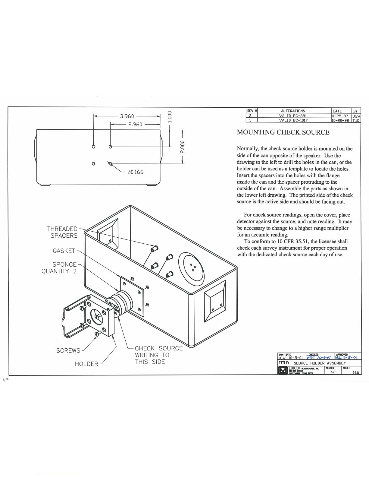


Model 2241-2 Technical Manual Appendix A
A
Appendix
RS-232 Output Formats
The Ludlum Model 2241 series of instruments has an RS-232 serial
communications port that can be used to log readings and read or set
instrument parameters. There are two formats available. Most Model 2241
instruments have the binary format outlined below, but some newer Model
2241-2 units have an ASCII output, which is also outlined below following
the binary format explanation.
The RS-232 port is configured at 9600 baud, 8 data bits, no parity, and 1
stop bit (9600,8,N,1). Ludlum Measurements can supply a Windows-based
software that can be used to help calibrate the instruments, but note that it
will not communicate with the newer ASCII output Model 2241-2 units.
Binary Output Format (15 Bytes)
BYTE01 RatemeterCPS+0 MSB
BYTE02 RatemeterCPS+1
BYTE03 RatemeterCPS+2
BYTE04 RatemeterCPE+3 LSB
BYTE05 Scaler+0 MSB
BYTE06 Sclaer+1
BYTE07 Scaler+2
BYTE08 Scaler+3
BYTE09 Scaler+4 LSB
BYTE10 CountTime+0 MSB
BYTE11 CountTime+1 LSB
BYTE12 CountTimeLeft+0 MSB
BYTE13 CountTimeLeft+1 LSB
BYTE14 Carriage Return (0DH)
BYTE15 Line Feed (0AH)
The ratemeter value is in cps and is scaled by a factor of 256. To get the
ratemeter reading in cpm, take the value and divide by 256, and then
multiply by 60.
Ludlum Measurements, Inc. Page A-1 January 2016

Model 2241-2 Technical Manual Appendix A
RS-232 Commands
E – auto dump off
A – auto dump on
C – start scaler
F – set scaler count time
R – send parameters from instrument to computer
S – read parameters from computer to instrument
O – output once
All commands must be sent in upper case laters.
Output of “R” Command – Read Parameters
BYTE01 Detector+0
BYTE02 DeadConstant+0 MSB
BYTE03 DeadConstant+1 LSB
BYTE04 CaConstant+0 MSB
BYTE05 CalConstant+1
BYTE06 CalConstant+2
BYTE07 CalConstant+3
BYTE08 CalConstant+4
BYTE09 CalConstant+5 LSB
BYTE10 RateAlarm+0 MSB
BYTE11 RateAlarm+1
BYTE12 RateAlarm+2
BYTE13 RateAlarm+3
BYTE14 RateAlarm+4 LSB
BYTE15 ScalerAlarm+0 MSB
BYTE16 ScalerAlarm+1
BYTE17 ScalerAlarm+2
BYTE18 ScalerAlarm+3
BYTE19 ScalerAlarm+4 LSB
BYTE20 CountTime+0 MSB
BYTE21 CountTime+1 LSB
BYTE22 Units+0
BYTE23 TimeBase+0
BYTE24 AudioDivideBy+0
BYTE25 Response+0
BYTE26 RateAlert+0 MSB
BYTE27 RateAlert+1
BYTE28 RateAlert+2
BYTE29 RateAlert+3
BYTE30 RateAlert+4 LSB
BYTE31 CheckSource+0 MSB
BYTE32 CheckSource+1
BYTE33 CheckSource+2
Ludlum Measurements, Inc. Page A-2 January 2016

Model 2241-2 Technical Manual Appendix A
BYTE34 CheckSource+3
BYTE35 CheckSource+4 LSB
BYTE36 PercentCS+0
BYTE37 MinDisplay+0
BYTE38 Carriage Return (0DH)
BYTE39 Line Feed (0AH)
Input of “S” Command – Send Parameters
BYTE1 DeadCosntant+0 MSB
BYTE2 DeadConstant+1 LSB
BYTE3 CalConstant+0 MSB
BYTE4 CalConstant+1
BYTE5 CalConstant+2
BYTE6 CalCosntant+3
BYTE7 CalConstant+4
BYTE8 CalConstant+5 LSB
BYTE9 RateAlarm+0 MSB
BYTE10 RateAlarm+1
BYTE11 RateAlarm+2
BYTE12 RateAlarm+3
BYTE13 RateAlarm+4 LSB
BYTE14 ScalerAlarm+0 MSB
BYTE15 ScalerAlarm+1
BYTE16 ScalerAlarm+2
BYTE17 ScalerAlarm+3
BYTE18 ScalerAlarm+4 LSB
BYTE19 CountTime+0 MSB
BYTE20 CountTime+1 LSB
BYTE21 Units+0
BYTE22 TimeBase+0
BYTE23 AudioDivdeBy+0
BYTE24 Response+0
BYTE25 RateAlert+0 MSB
BYTE26 RateAlert+1
BYTE27 RateAlert+2
BYTE28 RateAlert+3
BYTE29 RateAlert+4 LSB
BYTE30 CheckSource+0 MSB
BYTE31 CheckSource+1
BYTE32 CheckSource+2
BYTE33 CheckSource+3
BYTE34 CheckSource+4 LSB
BYTE35 PercentCS+0
BYTE36 MinDisplay+0
Ludlum Measurements, Inc. Page A-3 January 2016

Model 2241-2 Technical Manual Appendix A
Input of “F” Command – Set Count Time
BYTE1 CountTime+0 MSB
BYTE2 CountTime+1 LSB
Units 0 = R
1 = Sv
2 = cpm
Timebase 0 = min
1 = seconds
AudioDivide 0 = Auto
1 = Manual
ASCII Output F ormat
This special firmware changes the format of the auto-dump from binary to
ASCII. The output interval remains the same (2 seconds).
2241 Special Firmware 40804n10 08/06/2003
2241-2 Special Firmware 40806n13 04/04/2003
2241-3 Special Firmware 40806n16 07/07/2004
The old format was (binary):
Byte 1 Ratemeter CPS + 0
Byte 2 Ratemeter CPS + 1
Byte 3 Ratemeter CPS + 2
Byte 4 Ratemeter CPS + 3
Byte 5 Scaler + 0
Byte 6 Scaler + 1
Byte 7 Scaler + 2
Byte 8 Scaler + 3
Byte 9 Scaler + 4
Byte 10 Count Time + 0
Byte 11 Count Time + 1
Byte 12 Count Time Left + 0
Byte 13 Count Time Left + 1
Byte 14 Carriage Return (0DH)
Byte 15 Line Feed (0AH)
and is now replaced with (ASCII):
byte 1 x Ratemeter
byte 2 x Raetemter
byte 3 x Ratemeter
byte 4 x Ratemeter
byte 5 x Ratemeter
byte 6 y Display units
byte 7 Carriage Return (0DH)
Ludlum Measurements, Inc. Page A-4 January 2016

Model 2241-2 Technical Manual Appendix A
byte 8 Line Feed (0AH)
The ratemeter is displayed as 5 ASCII digits with a decimal, if necessary, and
matches the LCD display on the 2241-2.
The display mode is a value from 0 to 9 representing the display units.
CPS 0
KCPS 1
CPM 2
KCPM 3
µR 4
mR 5
R 6
µSv 7
mSv 8
Sv 9
Note: The LMI Model 2241 calibration software is not compatible with this
firmware version.
Example output:
02.991 (=2.99 kcps)
01.801 (=1.80 kcps)
01.221 (=1.22 kcps)
00.831 (=0.83 kcps)
00.581 (=0.58 kcps)
004160 (=416 cps)
Ludlum Measurements, Inc. Page A-5 January 2016
 Loading...