


LUDLUM MODEL 19
MICRO R METER
February 2012
Serial Number 207422 and Succeeding
Serial Numbers

LUDLUM MODEL 19
MICRO R METER
February 2012
Serial Number 207422 and Succeeding
Serial Numbers


Table of Contents
Introduction 1
Getting Started 2
Unpacking and Repacking 2-1
Battery Installation 2-1
Operational Check 2-2
Maintenance 2-3
Recalibration 2-3
Batteries 2-3
Specifications 3
Identification of Contr ols and Functions 4
Safety Considerations 5
Environmental Conditions for Normal Use 5-1
Warning Markings and Symbols 5-1
Cleaning and Maintenance Precautions 5-2
Troubleshooting 6
Troubleshooting Electronics which utilize a Scintillation Detector 6-1
Technical Theory of Operat ion 7
Detector 7-1
Input 7-1
Amplifier 7-1
Discriminator 7-1
Audio 7-2
Scale Ranging 7-2
Digital Analog Converter 7-2
Meter Drive 7-2
Fast/Slow Time Constant 7-2
Low Voltage Supply 7-2
High Voltage Test 7-2
High Voltage Supply 7-3
Ludlum Measurements, Inc. February 2012

Model 19 MICRO R METER Technical Manual
Recycling 8
Parts List 9
Model 19 Micro R Meter 9-1
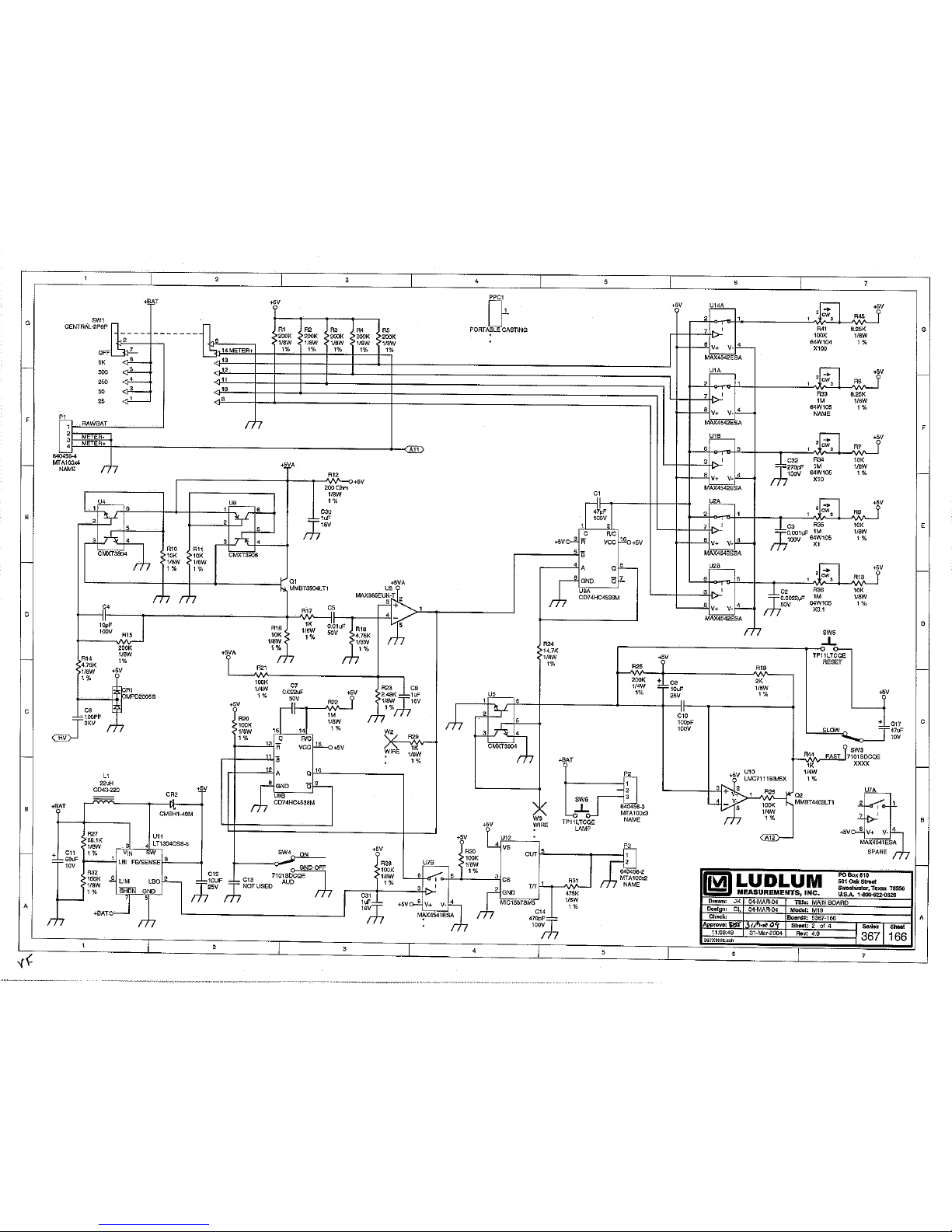
Main Board, Drawing 367 × 166 9-1
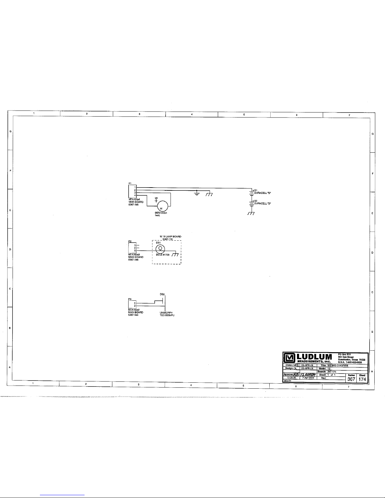
Wiring Diagram, Drawing 367 × 174 9-4
Drawings and Diagrams 10
Ludlum Measurements, Inc. February 2012

Model 19 MICRO R METER Technical Manual Section 1
Section
1
T
Introduction
he Ludlum Model 19 Micro R Meter utilizes an internally-mounted
2.5 x 2.5 cm (1 × 1 in.) NaI(T1) scintillator for optimum
performance in locating and measuring low-level (near background)
gamma radiation.
The unit features a push-button, lighted meter and was designed to be
moisture and dust resistant. The meter is housed in a rugged aluminum bezel
with waterproof seals. All controls, including a calibration potentiometer for
each range, are located on the front panel. Front-panel switches are rubberbooted to seal out moisture and dust. A high-voltage (HV) test control is
provided to allow rapid plateau testing of the detector.
Five range divisions are provided in the 0-5000 micro R/hr spectrum. The
meter face is made up of two scales, 0-50 and 0-25, plus battery test. The 050 scale corresponds to the 50, 500 and 5000 positions on the range selector
switch. The 0-25 scale corresponds to the 25 and 250 positions on the range
selector switch.
The instrument is capable of using either standard "D" cell flashlight
batteries or nickel-cadmium rechargeable batteries. However, the Model 19
does not include circuitry for recharging the batteries. The two "D" cell
batteries are located in an isolated compartment, easily accessible from the
front panel.
The Model 19 NaI scintillator is energy sensitive. An energy response curve
is included in section 10 of this manual for further reference.
Ludlum Measurements, Inc. Page 1-1 February 2012

Model 19 MICRO R METER Technical Manual Section 2
Section
2
Getting Started
Unpacki ng and Repac king
Remove the calibration certificate and place it in a secure location. Remove
the instrument and accessories (batteries, cable, etc.) and ensure that all of
the items listed on the packing list are in the carton. Check individual item
serial numbers and ensure calibration certificates match. The Model 19 serial
number is located on the front panel below the battery compartment. Most
Ludlum Measurements, Inc. detectors have a label on the base or body of
the detector for model and serial number identification.
Important!
If multiple shipments are received, ensure that the detectors
and instruments are not interchanged. Each instrument is
calibrated to specific detectors, and therefore, not
interchangeable.
To return an instrument for repair or calibration, provide sufficient packing
material to prevent damage during shipment. Also provide appropriate
warning labels to ensure careful handling. Include detector(s) and related
cable(s) for calibration. Include brief information as to the reason for return,
as well as return shipping instructions:
- Return shipping address
- Customer name or contact
- Telephone number
- Description of service requested and all other necessary
information
Battery Installation
Ensure the Model 19 power switch is in the “OFF” position. Open the
battery lid by pushing down and turning the quarter-turn thumbscrew
counterclockwise a quarter of a turn. Install two "D" size batteries in the
compartment.
Ludlum Measurements, Inc. Page 2-1 February 2012

Model 19 MICRO R METER Technical Manual Section 2
Note the (+) and (-) marks inside the battery door. Match the battery
polarity to these marks. Close the battery box lid, push down and turn the
quarter-turn thumb screw clockwise a quarter of a turn.
Note:
Center post of a flashlight battery is positive. The batteries are
placed in the battery compartment in opposite directions.
Operational C heck
Turn the range selector switch to the “25” position. Depress the “BAT”
pushbutton switch and ensure that the meter needle falls within the “BAT
OK
” marks. Check for a proper background reading. A typical reading would
be: 5-15 uR/hr
Turn the range selector switch to the “5000” position. Expose the
instrument to a check source and verify that the instrument indicates within
20% of the check source reading obtained during the last calibration.
Switch the “AUD ON/OFF” switch to the “ON” position and confirm that the
external unimorph speaker produces an audible click for each event
detected. The “AUD ON/OFF” switch will silence the audible clicks if in the
“OFF” position. It is recommended that the “AUD ON/OFF” switch be kept
in the “OFF” position when not needed in order to preserve battery life.
Turn the range selector switch to the “250” position and increase the source
activity for a meter reading of 10-100 uR/hr. While observing the meter
fluctuations, select between the fast and slow response time (F/S) positions
to observe variations in the display. The "S" position should respond
approximately five times slower than the “F” position.
Note:
The slow response position is normally used when the
instrument is displaying low numbers, which require a
more stable meter movement. The fast response position is
used at high rate levels.
Check the meter reset function by depressing RESET and ensuring the meter
needle drops to “0.”
Ludlum Measurements, Inc. Page 2-2 February 2012

Model 19 MICRO R METER Technical Manual Section 2
Depress the “LAMP” pushbutton switch. Ensure that the meter face
illuminates when the switch is depressed. Proceed to use the instrument.
Maintenance
Instrument maintenance consists of keeping the instrument clean and
periodically checking the batteries and the calibration. The Model 19
instrument may be cleaned with a damp cloth (using only water as the
wetting agent). Do not immerse instrument in any liquid. Observe the
following precautions when cleaning:
1. Turn the instrument off and remove the batteries.
2. Allow the instrument to sit for one minute before accessing
internal components.
Recalibration
Recalibration should be accomplished after any maintenance or adjustment
of any kind has been performed on the instrument. Battery replacements are
not considered maintenance and do not normally require instrument
recalibration.
Note:
Ludlum Measurements, Inc. recommends recalibration at
intervals no greater than one year. Check the appropriate
regulations to determine required recalibration intervals.
Ludlum Measurements offers a full-service repair and calibration
department. We not only repair and calibrate our own instruments but most
other manufacturers’ instruments. Calibration procedures are available upon
request for customers who choose to calibrate their own instruments.
Batteries
The batteries should be removed any time the instrument is placed into
storage. Battery leakage may cause corrosion on the battery contacts, which
must be scraped off and/or washed using a paste solution made from
baking soda and water. Use a spanner wrench to unscrew the battery contact
Ludlum Measurements, Inc. Page 2-3 February 2012

Model 19 MICRO R METER Technical Manual Section 2
insulators, exposing the internal contacts and battery springs. Removal of the
handle will facilitate access to these contacts.
Note:
Never store the instrument over 30 days without removing the
batteries. Although this instrument will operate at very high
ambient temperatures, battery seal failure may occur at
temperatures as low as 37 °C (100 °F).
Ludlum Measurements, Inc. Page 2-4 February 2012

Model 19 MICRO R METER Technical Manual Section 3
Section
3
Specifications
0
Linearity: reading within 10% of true value
High Voltage: variable from 400 to 1500 Vdc; electronically regulated to
within 1%
Battery Dependence: instrument calibration change less than 3%
within the meter battery check limits
Power: two standard alkaline "D" cell batteries, secured in an isolated
compartment
Battery Life: expected lifetime of approximately 2000 hours with the
“AUD ON/OFF” switch in the OFF position
Audio Output: built-in unimorph speaker and “ON/OFF” switch
provided on the front panel
Counting Ranges: two-scale meter face presenting 0-50 µR/hr with full
scale range positions of 5000, 500 and 50; and 0-25 µR/hr with full scale
range positions of 250 and 25.
Meter: 1 mA, 6.4 cm (2.5 in.) scale, pivot-and-jewel suspension
Detector: photomultiplier coupled to a 2.5 x 2.5 (1 × 1 in.) NaI(Tl)
crystal, mounted inside the instrument housing
Construction: cast-and-drawn aluminum with beige powder-coat finish
and printed membrane front panel
Size: 15.2 x 8.9 x 21.6 cm (6.0 x 3.5 x 8.5 in.), not including instrument
handle
Weight: 2.04 kg (4.5 lb), including batteries
Ludlum Measurements, Inc. Page 3-1 February 2012

Model 19 MICRO R METER Technical Manual Section 4
Section
4
Identification of Controls and
Functions
Range Selector Switch: a six-position switch marked OFF, 5000, 500,
250, 50, and 25. Moving the range selector switch to one of the range
positions (5000, 500, 250, 50, 25) provides the operator with an overall
range of 0-5000 µR/hr. Note that the range positions 5000, 500 and 50
are screened in black and correspond to the meter scale screened in
black. The range positions 250 and 25 are screened in red and
correspond to the meter scale screened in red.
AUD ON-OFF Toggle Switch: In the ON position, the switch operates
the unimorph speaker, located on the left side of the instrument. The
frequency of the clicks is relative to the rate of the incoming pulses. The
higher the rate is, the higher the audio frequency. The audio should be
turned OFF when not required in order to reduce battery drain.
F-S Toggle Switch: provides meter response. Selecting the fast, "F,"
position of the toggle switch provides 90% of full-scale meter deflection
in four seconds. In the slow, "S," position, 90% of full-scale meter
deflection takes 22 seconds. In "F" position, there is fast response and
large meter deviation. The "S" position should be used for slow response
and damped, meter deviation.
BAT Pushbutton Switch: when depressed, this switch indicates the
battery charge status on the meter. The range selector switch must be
out of the OFF position.
RES Pushbutton Switch: When depressed, this switch provides a rapid
means to drive the meter to zero.
LAMP Pushbutton Switch: When depressed, this switch lights the meter
face.
HV Pushbutton Switch: When depressed, the meter reads the detector
high voltage. Each meter division is equivalent to 100 V.
Ludlum Measurements, Inc. Page 4-1 February 2012

Model 19 MICRO R METER Technical Manual Section 4
HV Adjustment: provides a means to vary the high voltage from 400 to
1500 V.
Range Calibration Adjustments: recessed potentiometers located under
the calibration cover on the right side of the front panel. These
adjustment controls allow individual calibration for each range
multiplier.
Ludlum Measurements, Inc. Page 4-2 February 2012

Model 19 MICRO R METER Technical Manual Section 5
Section
5
Safety Considerations
Environment al Conditions for Normal Use
Indoor or outdoor use
No maximum altitude
Temperature range of -20 to 50 °C (-4 to 122 °F)
Maximum relative humidity of less than 95% (non-condensing)
Pollution Degree 3 (as defined by IEC 664) (Occurs when conductive
pollution or dry nonconductive pollution becomes conductive due to
condensation. This is typical of industrial or construction sites.)
Warning Markings and Symbols
Caution!
The operator or responsible body is cautioned that the
protection provided by the equipment may be impaired if
the equipment is used in a manner not specified by Ludlum
Measurements, Inc.
The Model 19 Micro R Meter is marked with the
following symbols:
CAUTION (per ISO 3864, No. B.3.1) – designates hazardous live voltage
and risk of electric shock. During normal use, internal components are
hazardous live. This instrument must be isolated or disconnected from the
hazardous live voltage before accessing the internal components. This
symbol appears on the front panel. Note the following precautions:
Ludlum Measurements, Inc. Page 5-1 February 2012
Model 19 MICRO R METER Technical Manual Section 5
Warning!
The operator is strongly cautioned to take the following
precautions to avoid contact with internal hazardous live
parts that are accessible using a tool:
1. Turn the instrument power OFF and remove the batteries.
2. Allow the instrument to sit for one minute before accessing
internal components.
The “crossed-out wheelie bin” symbol notifies the consumer that the
product is not to be mixed with unsorted municipal waste when discarding;
each material must be separated. The symbol is placed on the battery
compartment lid. See section 8, “Recycling,” for further information.
The “CE” mark is used to identify this instrument as being acceptable
for use within the European Union.
Cleaning and Maintenance Precautions
The Model 19 may be cleaned externally with a damp cloth, using only water
as the wetting agent. Do not immerse the instrument in any liquid. Observe
the following precautions when cleaning or performing maintenance on the
instrument:
1. Turn the instrument OFF and remove the batteries.
2. Allow the instrument to sit for one minute before cleaning the
exterior or accessing any internal components for maintenance.
Ludlum Measurements, Inc. Page 5-2 February 2012

Model 19 MICRO R METER Technical Manual Section 6
Section
6
O
Troubleshooting
ccasionally, you may encounter problems with your LMI
instrument or detector that may be repaired or resolved in the
field, saving turn-around time and expense in returning the
instrument to us for repair. Toward that end, LMI electronics
technicians offer the following tips for troubleshooting the most common
problems. Where several steps are given, perform them in order until the
problem is corrected. Keep in mind that with this instrument, the most
common problems encountered are: (1) sticky meters; and (2) battery
contacts.
Note that the first troubleshooting tip is for determining whether the
problem is with the electronics or with the detector. A Ludlum Model 500
Pulser is invaluable at this point, because of its ability to simultaneously
check high voltage, input sensitivity or threshold, and the electronics for
proper counting.
We hope these tips will prove to be helpful. As always, please call if you
encounter difficulty in resolving a problem or if you have any questions.
T roubleshooti ng Electronics which utili ze a
Scintilla tion Detector
SYMPTOM
No power (or meter
does not reach BAT
or BAT OK
TEST
mark)
POSSIBLE SOLUTION
1. Check batteries and replace if weak.
2. Check polarity (see marks inside
batter lid). Are the batteries installed
backwards?
Ludlum Measurements, Inc. Page 6-1 February 2012

Model 19 MICRO R METER Technical Manual Section 6
SYMPTOM
No power (or meter
does not reach BAT
TEST
or BAT OK
mark) (continued)
Nonlinear Readings
Meter goes full-scale
or “pegs out”
POSSIBLE SOLUTION
3. Check battery contacts. Clean them
with rough sandpaper or use an
engraver to clean the tips.
4. Check for loose or broken wires,
especially between the main board
and the calibration board.
1. Check the high voltage (HV) by
pressing the HV TEST button. If a
multimeter is used to check the HV,
ensure that one with high impedance
is used, as a standard multimeter
could be damaged in this process.
2. Check for “sticky” meter movement.
Does the reading change when you
tap the meter? Does the meter needle
“stick” at any spot?
3. Check the “meter zero.” Turn the
power OFF. The meter should come
to rest on “0.”
1. Check the HV and, if possible, the
input threshold for proper setting.
2. Check for loose wires, especially
between the main board and the
calibration board.
Ludlum Measurements, Inc. Page 6-2 February 2012

Model 19 MICRO R METER Technical Manual Section 7
Section
7
T echnical Theory of Operation
Detector
The detector consists of a crystal of sodium iodide with Thallium activation
(NaI Tl) that gives off light pulses when penetrated by radiation photons.
The light pulses are converted to electrical pulses by the photo cathode of
the photomultiplier tube. The photomultiplier includes a nine-stage electron
amplifier. This amplifier utilizes an electrostatic field for each stage, adding
up to a required 500 to 1500 V supply.
Input
Detector pulses are coupled from the detector through C6 to the amplifier.
CR1 protects the amplifier from input shorts. R37 couples the detector to
the high-voltage supply.
Amplifier
A self-biased amplifier provides gain in proportion to R15 and C4 divided by
R14. Transistor (pin 3 of U4) provides amplification. U6 is configured as a
current mirror to provide a load for pin 3 of U4. The output self biases to 2
Vbe (approximately 1.4 volts) at emitter of Q1. This provides just enough
bias current through pin 3 of U4 to conduct all of the current from the
current mirror.
Positive pulses at R16 are coupled to the discriminator through C5.
Discriminator
Comparator U8 provides discrimination. The discriminator is set by the
voltage divider, R21 and R23, coupled to pin 3 of U8. U8 output pulses are
coupled to pin 5 of U9A for meter drive and pin 12 of U9B for audio.
Ludlum Measurements, Inc. Page 7-1 February 2012

Model 19 MICRO R METER Technical Manual Section 7
Audio
Discriminator pulses are coupled to univibrator pin 12 of U9B. Front-panel
audio ON-OFF selector controls the reset at pin 13 of U9B. When ON, pulses
from pin 10 of U9B turn on oscillator U12, which drives the can-mounted
unimorph. Speaker tone is set by R31, C14; duration by R22, C7.
Scale Ranging
Detector pulses from the discriminator are coupled to univibrator pin 5 of
U9A. For each scale, the pulse width of pin 6 of U9A is controlled by the
front-panel calibration controls and their related capacitors. This
arrangement allows the same current to be delivered to C9 in proportion to
the meter reading.
Digital Analog C onverter
U5 is configured as a current mirror. For each pulse of current through R24,
an equal current is delivered to C9. This charge is drained off by R25. The
voltage across C9 is proportional to the incoming count rate.
Meter Drive
The meter is driven by the collector of Q2 coupled as a voltage follower in
conjunction with pin 1 of U10.
For the battery test, the voltage follower is bypassed and the meter
movement is directly coupled to the battery through R8.
Fast/Slow Time Const ant
For slow-time constant, C17 is switched from the output of the meter drive
to parallel C9.
Low V oltage Supply
Battery voltage is coupled to U11 and associated components (a switching
regulator) to provide 5 V at pin 8 to power all circuits.
High V oltage T est
A constant current is developed by collector of Q3 in proportion to HV
signal at pin 1 of U17. U16 provides a current mirror to drive the meter
Ludlum Measurements, Inc. Page 7-2 February 2012

Model 19 MICRO R METER Technical Manual Section 7
through analog switch logic circuit U15, U14, and U3.
High V oltage Supply
High voltage is developed by switching regulator U13 and T1. Voltage
multiplier CR3 thru CR7, and associated components, develop the detector
voltage. Voltage feedback is provided by R39 thru U17 to feed back pin 8 of
U13 for voltage regulation. Pin 1 of U17 is proportional to the high voltage,
and its output is also utilized to measure the high voltage. High voltage is
adjusted by varying the feedback current with R42.
Ludlum Measurements, Inc. Page 7-3 February 2012

Model 19 MICRO R METER Technical Manual Section 8
Section
8
L
Recycling
udlum Measurements, Inc. supports the recycling of the electronics
products it produces for the purpose of protecting the environment
and to comply with all regional, national, and international agencies
that promote economically and environmentally sustainable
recycling systems. To this end, Ludlum Measurements, Inc. strives to supply
the consumer of its goods with information regarding reuse and recycling of
the many different types of materials used in its products. With many
different agencies – public and private – involved in this pursuit, it becomes
evident that a myriad of methods can be used in the process of recycling.
Therefore, Ludlum Measurements, Inc. does not suggest one particular
method over another, but simply desires to inform its consumers of the
range of recyclable materials present in its products, so that the user will
have flexibility in following all local and federal laws.
The following types of recyclable materials are present in Ludlum
Measurements, Inc. electronics products, and should be recycled separately.
The list is not all-inclusive, nor does it suggest that all materials are present in
each piece of equipment:
Batteries Glass Aluminum and Stainless Steel
Circuit Boards Plastics Liquid Crystal Display (LCD)
Ludlum Measurements, Inc. products, which have been placed on the
market after August 13, 2005, have been labeled with a symbol recognized
internationally as the “crossed-out wheelie bin.” This notifies the consumer
that the product is not to be mixed with unsorted municipal waste when
discarding; each material must be separated. The symbol will be placed near
the AC receptacle, except for portable equipment where it will be placed on
the battery lid.
The symbol appears as such:
Ludlum Measurements, Inc. Page 8-1 February 2012

Model 19 MICRO R METER Technical Manual Section 9
Section
9
Parts List
Model 19
Micro R Meter
Main Board,
Drawing 367 × 166
CAPACITORS
Reference Description
UNIT Completely Assembled
Model 19 Micro R Meter 48-1615
BOARD Completely Assembled
Circuit Board 5367-166
C1 47pF, 100V 04-5660
C2 0.0022µF, 50V 04-5676
C3 0.001µF, 100V 04-5659
C4 10pF, 100V 04-5673
C5 0.01µF, 50V 04-5664
C6 100pF, 3KV 04-5735
C7 0.022µF, 50V 04-5667
C8 1µF, 16V 04-5701
C9 10µF, 25V 04-5655
C10 100pF, 100V 04-5661
C11 68µF, 10V 04-5654
C12 10µF, 25V 04-5728
C14 470pF, 100V 04-5668
C17 47µF, 10V 04-5666
C18-C27 0.01µF, 500V 04-5696
C28 0.001µF, 2KV 04-5703
C29 68µF, 10V 04-5654
C30-C31 1µF, 16V 04-5701
C32 270pF, 100V 04-5679
C33 0.01µF, 50V 04-5664
Part Number
Ludlum Measurements, Inc. Page 9-1 February 2012

Model 19 MICRO R METER Technical Manual Section 9
VOLTAGE
INTEGRATED
DIODES
SWITCHES
POTENTIOMETERS /
TRANSISTORS
REGULATOR
CIRCUITS
TRIMMERS
Reference Description
Part Number
Q1 MMBT3904LT1 05-5841
Q2 MMBT4403LT1 05-5842
Q3 MMBT3904LT1 05-5841
VR1 LT1460KCS3-2.5TR 05-5867
U1-U3 MAX4542ESA 06-6453
U4-U5 CMXT3904 05-5888
U6 CMXT3906 05-5890
U7 MAX4541ESA 06-6452
U8 MAX985EUK-T 06-6459
U9 CD74HC4538M 06-6297
U10 LMC7111BIM5X 06-6410
U11 LT1304CS8-5 06-6434
U12 MIC1557BM5 06-6457
U13 LT1304CS8 06-6394
U14-U15 MAX4542ESA 06-6453
U16 CMXT3906 05-5890
U17-C18 LMC7111BIM5X 06-6410
CR1 CMPD2005S 07-6468
CR2 CMSH1-40M 07-6411
CR3-CR7 CMPD2005S 07-6468
CR9 CMSH1-40M 07-6411
SW1 RANGE SELECTOR 08-6761
SW2 H.V. PUSHBUTTON 08-6770
SW3 F-S TOGGLE 08-6781
SW4 AUD ON-OFF TOGGLE 08-6781
SW5 RES PUSHBUTTON 08-6770
SW6 LAMP PUSHBUTTON 08-6770
SW7 BAT PUSHBUTTON 08-6770
R33 1M, 64W105 NAME 09-6814
R34 1M, 64W105 X10 09-6814
R35 1M, 64W105 X1 09-6814
R36 1M, 64W105 X0.1 09-6814
R41 100K, 64W104 X100 09-6813
Ludlum Measurements, Inc. Page 9-2 February 2012

Model 19 MICRO R METER Technical Manual Section 9
RESISTORS
CONNECTORS
Reference Description
Part Number
R42 100K, 64W104 HV ADJ 09-6813
R52 10K, 3266X1-103 NAME 09-6822
R1-R5 200K, 1/8W, 1% 12-7992
R6 8.25K, 1/8W, 1% 12-7838
R7 10K, 1/8W, 1% 12-7839
R8 2.37K, 1/8W, 1% 12-7861
R9-R11 10K, 1/8W, 1% 12-7839
R12 200 Ohm, 1/8W, 1% 12-7846
R13 10K, 1/8W, 1% 12-7839
R14 4.75K, 1/8W, 1% 12-7858
R15 200K, 1/8W, 1% 12-7992
R16 10K, 1/8W, 1% 12-7839
R17 1K, 1/8W, 1% 12-7832
R18 4.75K, 1/8W, 1% 12-7858
R19 2K, 1/8W, 1% 12-7926
R20-R21 100K, 1/4W, 1% 12-7834
R22 1M, 1/8W, 1% 12-7844
R23 2.49K, 1/8W, 1% 12-7999
R24 14.7K, 1/8W, 1% 12-7068
R25 200K, 1/4W, 1% 12-7992
R26 100K, 1/4W, 1% 12-7834
R27 68.1K, 1/8W, 1% 12-7881
R28 100K, 1/8W, 1% 12-7834
R29 1K, 1/8W, 1% 12-7832
R30 100K, 1/8W, 1% 12-7834
R31 475K, 1/8W, 1% 12-7859
R32 100K, 1/8W, 1% 12-7834
R37 100K, 1/8W, 1% 12-7834
R38 4.75M, 1/8W, 1% 12-7995
R39 500M, 3KV, 2% 12-7031
R40 1M, 1/4W, 1% 12-7844
R44 1K, 1/4W, 1% 12-7832
R45 8.25K, 1/8W, 1% 12-7838
R46-R48 200K, 1/4W, 1% 12-7992
R49 825K, 1/8W, 1% 12-7005
R50 953K, 1/8W, 1% 12-7950
R53 1K, 1/4W, 1% 12-7832
P1 CONN-640456-4
MTA100x4 NAME 13-8088
Ludlum Measurements, Inc. Page 9-3 February 2012

Model 19 MICRO R METER Technical Manual Section 9
INDUCTOR
TRANSFORMER
AUDIO
CONNECTOR
BATTERY
MISCELLANEOUS
Wiring Diagram,
Drawing 367 × 174
Reference Description
Part Number
P2 CONN-640456-3
MTA100x3 NAME 13-8081
P3 CONN-640456-2
MTA100x2 NAME 13-8073
P4 CONTACT #1434 NAME 18-9124
L1 22µH, CD43-220 21-9808
T1 31032R 21-9925
DS1 Model 19 LAMP BOARD 5367-113
5367-113
DS2 UNIMORPH TEC-3526-PU 21-9251
P1 MTA100x4 MAIN BOARD
5367-166 13-8170
P2 MTA 100x3 MAIN BOARD
5367-166 13-8135
P3 MTA 100x2 MAIN BOARD
5367-166 13-8178
B1-B2 DURACELL "D" 21-9313
* MODEL 19 INTERNAL DETECTOR
47-3426
* TUBE/XTAL ASSY 2004-061
M1 MODEL 19 METER
ASSY 987010-001 1mA 4367-024
* MODEL 19 METERFACE
(202-016) 7367-023
* METER BEZEL W/ GLASS
W/ SCREWS 4363-352-00
* METER MOVEMENT (1mA) 15-8030
* Model 19 BATTERY BOX
LID W/CNTCT 2363-191
* DEEP PORTABLE
CAN ASSY 4363-615
* MODEL 19 CASTING 7367-171
* MODEL 19 MAIN HARNESS 8367-170
Ludlum Measurements, Inc. Page 9-4 February 2012

Model 19 MICRO R METER Technical Manual Section 9
Reference Description
Part Number
* PORTABLE KNOB 08-6613
* SWITCH SEAL (P/B) 08-6611
* UNIMORPH W/WIRES,
O'RING 40-0034
* CAL COVER W/SCREWS 4363-200
* HANDLE- PORTABLE (GRIP) 7363-139
Ludlum Measurements, Inc. Page 9-5 February 2012

Model 19 MICRO R METER Technical Manual Section 10
Section
10
Drawings
Model Board Circuit, Drawing 367 × 166 (4 sheets)
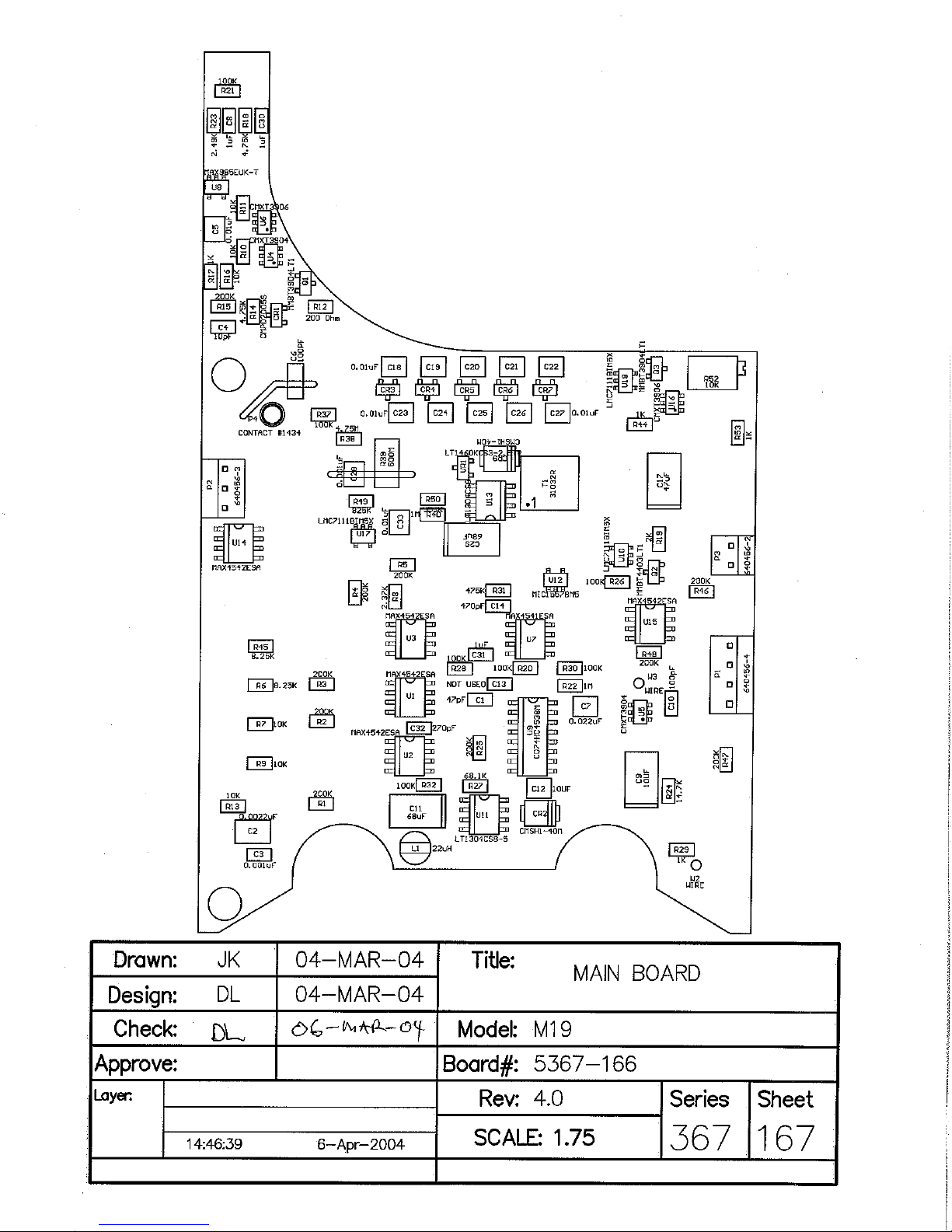
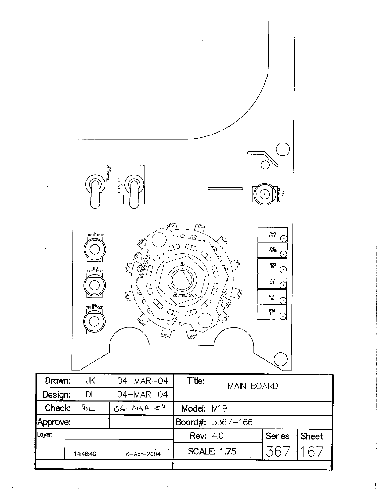
Model Board Component Layouts, Drawings 367 × 167 (2 sheets)
Wiring Diagram, Drawing 367 × 174
Energy Response for Ludlum Model 19
Ludlum Measurements, Inc. Page 10-1 February 2012


 Loading...