

Page 1

LUDLUM MODEL 9-3
ION CHAMBER
June 2018
Serial Number 261657 and Succeeding
Serial Numbers
Page 2

LUDLUM MODEL 9-3
ION CHAMBER
June 2018
Serial Number 261657 and Succeeding
Serial Numbers
Page 3
MODEL 9-3 Technical Manual
i
Page 4

MODEL 9-3 Technical Manual
STATEMENT OF WARRANTY
Ludlum Measurements, Inc. warrants the products covered in this manual to be free of
defects due to workmanship, material, and design for a period of twelve months from
the date of delivery. The calibration of a product is warranted to be within its
specified accuracy limits at the time of shipment. In the event of instrument failure,
notify Ludlum Measurements to determine if repair, recalibration, or replacement is
required.
This warranty excludes the replacement of photomultiplier tubes, G-M and
proportional tubes, and scintillation crystals which are broken due to excessive
physical abuse or used for purposes other than intended.
There are no warranties, express or implied, including without limitation any implied
warranty of merchantability or fitness, which extend beyond the description of the
face there of. If the product does not perform as warranted herein, purchaser’s sole
remedy shall be repair or replacement, at the option of Ludlum Measurements. In no
event will Ludlum Measurements be liable for damages, lost revenue, lost wages, or
any other incidental or consequential damages, arising from the purchase, use, or
inability to use product.
RETURN OF GOODS TO MANUFACTURER
If equipment needs to be returned to Ludlum Measurements, Inc. for repair or calibration, please
send to the address below. All shipments should include documentation containing return shipping
address, customer name, telephone number, description of service requested, and all other necessary
information. Your cooperation will expedite the return of your equipment.
LUDLUM MEASUREMENTS, INC.
ATTN: REPAIR DEPARTMENT
501 OAK STREET
SWEETWATER, TX 79556
800-622-0828 325-235-5494
FAX 325-235-4672
ii
Page 5

MODEL 9-3 Technical Manual
Table of Contents
Introduction 1
Getting Started 2
Battery Installation 2-1
Battery Test 2-1
Instrument Test 2-2
Operational Check 2-3
Specifications 3
Identification of Controls and Functions 4
Safety Considerations and Maintenance 5
Environmental Conditions for Normal Use 5-1
Warning Markings and Symbols 5-1
Metallized Polyester (Mylar) Window Precaution 5-2
Cleaning and Maintenance Precautions 5-2
Maintenance 5-3
Recalibration 5-3
Batteries 5-3
Desiccant 5-3
Return for Repair and Calibration 5-4
Technical Theory of Operation 6
Chamber 6-1
Chamber Window 6-1
Electrometer 6-1
Range Change 6-2
Reset 6-2
Offset Adjustment 6-2
Zero Adjust 6-2
iii
Page 6

MODEL 9-3 Technical Manual
Range Calibration 6-3
Range Changing 6-3
Power Supplies 6-3
Audio Circuit 6-4
Meter Circuit 6-4
Recycling 7
Parts List 8
Model 9-3 Ion Chamber 8-1
Main Circuit Board, Drawing 293 × 680 8-1
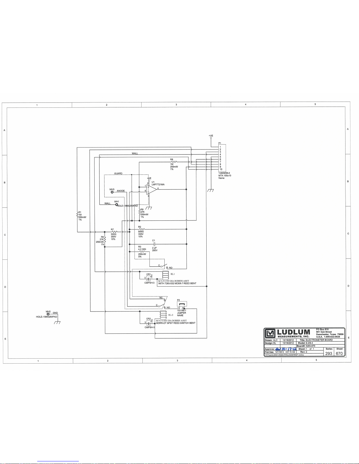
Electrometer Board, Drawing 293 × 670 8-4
Wiring Diagram, Drawing 293 x 525 8-5
Drawings and Diagrams 9
iv
Page 7

MODEL 9-3 Technical Manual Section 1
Section
1
T
Introduction
he Ludlum Model 9-3 is a five-range ion chamber instrument for
measuring beta-gamma radiation up to 50 R/hr. The chamber wall,
including the instrument case, is 1000 mg/cm². A 1000 mg/cm²
retractable beta shield allows beta measurement with a 7 mg/cm²
window.
The six-position selector switch selects OFF, ×10K, ×1K, ×100, ×10, and
×1. Each range has a front-panel mounted calibration control. Other
features include an audio pulsing in proportion to the meter reading,
RESET, and ZERO ADJUST. An additional calibration control “L” is
utilized to zero electrometer offset voltage.
The unit is powered by two “AA” cell batteries for operation from -20 to 50
°C (-4 to 122 °F).
Ludlum Measurements, Inc. Page 1-1 June 2018
Page 8

MODEL 9-3 Technical Manual Section 2
Section
2
Getting Started
Battery Installation
Ensure the Model 9-3 range selector switch is in the OFF position. Open the
battery lid by pushing down and turning the quarter-turn thumbscrew
counterclockwise one quarter of a turn. Install two “AA” size batteries in the
compartment.
Note the (+) and (-) marks inside the battery holder. Match the battery polarity
to these marks. Insert the negative end of the battery firmly against the spring
in the battery holder, then push the positive end of the battery forward to
ensure contact is made at both ends of the battery. Close the battery box lid,
then push down and turn the quarter-turn thumb screw clockwise one quarter
of a turn.
Note:
The center post of a battery is positive. The batteries are placed in
the battery compartment in opposite directions.
Battery Test
The batteries should be checked each time the instrument is turned on. This is
accomplished simply by pressing the BAT TEST button. Ensure that the meter
needle deflects to the battery test portion of the meter scale. If the meter does
not respond, check to see if the batteries have been correctly installed. Replace
the batteries if necessary.
Ludlum Measurements, Inc. Page 2-1 June 2018
Page 9

MODEL 9-3 Technical Manual Section 2
Instrument Test
Note:
The Model 9-3 has two options for chamber wall voltage. An
internal jumper may be selected to allow continuous voltage on
the chamber wall with the instrument turned off. This option
allows a faster, three-minute settling time when the instrument is
frequently used. If the instrument is infrequently used, it is
recommended that this option not be used, because of battery
drain. Battery life with the continuous wall voltage on and
instrument off is approximately six months.
Without this option, the battery drain is zero with the instrument
OFF. When the instrument is turned on, a settling time of 5
minutes is required for a reading of less than 0.2 mR/hr, 10
minutes for less than 0.1 mR/hr, and several hours for readings
near zero.
The instrument will be shipped with the chamber wall voltage
turned on when the instrument is turned off.
After checking the batteries with the range switch on the ×10K position, turn
the instrument range switch to the ×1 position. Note that as the selector switch
moves from ×100 to ×10, a meter transient will occur. This transient is caused
by an internal range relay and is normal. Allow time for the ×1 scale to stabilize.
Open the beta shield slide. Switch the AUD ON OFF switch to ON. Expose
the chamber window to a check source. Observe that the audio click frequency
increases as the meter reading increases.
Note:
The RESET circuit discharges the chamber and opens the
chamber connection to the electrometer. This causes a transient
on the ×1 and ×10 scales. The meter will indicate full scale and
count-down for five seconds when the RESET switch is pressed
and released. For near zero reading on ×1 scale, allow several
more seconds for setting time after RESET is released.
Ludlum Measurements, Inc. Page 2-2 June 2018
Page 10

MODEL 9-3 Technical Manual Section 2
Open the beta shield and expose the check source to the center of the chamber
window. The instrument reading should be within 20% of the check source
reference after settling time.
Note:
The depressions on the side of the instrument housing indicate the center
of the chamber.
Once this procedure has been completed, the instrument is ready for use. When
using the instrument, open the beta shield for greater beta response, and close
for less.
Caution!
Damage to the metalized polyester window on the back side of the
instrument may result when the slide is open if careful instrument
handling is not practiced. The window is very fragile and may be
punctured quite easily.
Operational Check
To assure proper operation of the instrument between calibrations and periods
of non-use, an instrument operational check, including battery test and
instrument test (as described above), should be performed prior to use. A
reference reading with a check source should be obtained at the time of initial
calibration, or as soon as possible, for use in confirming proper instrument
operation. In each case, ensure a proper reading on each scale. If the instrument
fails to read within 20% of a proper reading, it should be sent to a calibration
facility for recalibration.
Ludlum Measurements, Inc. Page 2-3 June 2018
Page 11

MODEL 9-3 Technical Manual Section 3
Section
3
Specifications
0
Range: typically 0.2-50,000 mR/hr.
Linearity: reading within 10% of true value.
Response: approximately five seconds for 90% of final meter deflection
on the ×1 scale and ×10, and two seconds on the remaining scales
Background: approximately every three minutes an up-scale “kick” may
be noted on the ×1 scale. This is due to normal cosmic background
radiation.
Chamber:
Chamber Wall Construction: carbon-coated acrylic
Chamber Volume: 220 cm
Window: 7 mg cm
Window Area: 40 cm
79% open screen)
2
metallized polyester
3
(13.4 in3)
2
(6.2 in3) (31.5 cm2 {4.9 in2}) open with optional
Beta Shield: retractable 1000 mg/cm
Beta Factor with the instrument exposed to a depleted uranium slab of
234 mrad/hr:
Reading with slide open: 50 mR/hr
Reading with slide closed: 1.2 mR/hr
Thus, Beta Factor = 234 divided by (50 minus 1.2) = 4.8
Energy Response: within 20% of true value from 40 keV to 2 MeV
Battery Dependence: Instrument calibration change is less than 5%
Ludlum Measurements, Inc. Page 3-1 June 2018
within battery check limits on the meter.
2
phenolic slide
Page 12

MODEL 9-3 Technical Manual Section 3
Warm-up Time: After power-up, ×100 through ×10K scales will be ready for
use in two minutes. For the ×1 scale and if the wall voltage option is on with
the instrument off, the scale will settle within 0.1 mR/hr within three minutes.
If the wall voltage option is off, allow 15 minutes for the ×1 scale to settle
within 0.1 mR/hr. Allow 30 minutes for the ×1 scale to settle to near zero in a
very low radiation field.
Magnetic Field Exposure: per ANSI 42-17A, magnetic fields of 800
A/m cause than a 15% deviation in instrument response
Instrument Controls
Multipliers: ×1, ×10, ×100, ×1K, and ×10K selected by a front-panel range
selector switch
Reset: The RESET circuit discharges the chamber and opens the chamber
connection to the electrometer. This causes a transient on the ×1 and ×10
scales. The meter will indicate full scale and count-down for five seconds when
the RESET switch is pressed and released. For near zero reading on ×1 scale,
allow several more seconds for setting time after RESET is released.
Battery Check: At 2.0 Vdc, the meter needle will drop to the edge of
the BAT OK area when the BAT TEST pushbutton is pressed. The audio
circuit will start clicking when the battery voltage drops to 1.9 V.
Zero Adjust: a control allowing limited background subtract and an
external one-turn potentiometer, also used to compensate electrometer
drift
Calibration Controls: individual potentiometers for each range;
accessible from the front cover while in operational status
Meter: 6.4 cm (2.5 in.) arc, 1 mA, pivot-and-jewel suspension
Meter Dial: 0-5 mR/hr, BAT TEST
Audio: built-in unimorph speaker with ON-OFF switch (greater than 60
dB at 61 cm {2 ft})
Power: two “AA” cell batteries housed in a sealed externally accessible
compartment
Battery Life: ×100 and higher ranges at full scale without display light, 1050
hours; at ×1 and ×10 in low background without display light, 1500 hours
Construction: cast-and-drawn aluminum with beige powder coating
Ludlum Measurements, Inc. Page 3-2 June 2018
Page 13

MODEL 9-3 Technical Manual Section 3
Temperature Range: -20 to 50 °C (-4 to 122 °F)
Dimensions: 23.4 x 8.9 x 21.6 cm (9.2 x 3.5 x 8.5 in.), including instrument
handle
Weight: 1.6 kg (3.6 lb), including batteries
Ludlum Measurements, Inc. Page 3-3 June 2018
Page 14

MODEL 9-3 Technical Manual Section 4
Section
4
Identification of Controls and
Functions
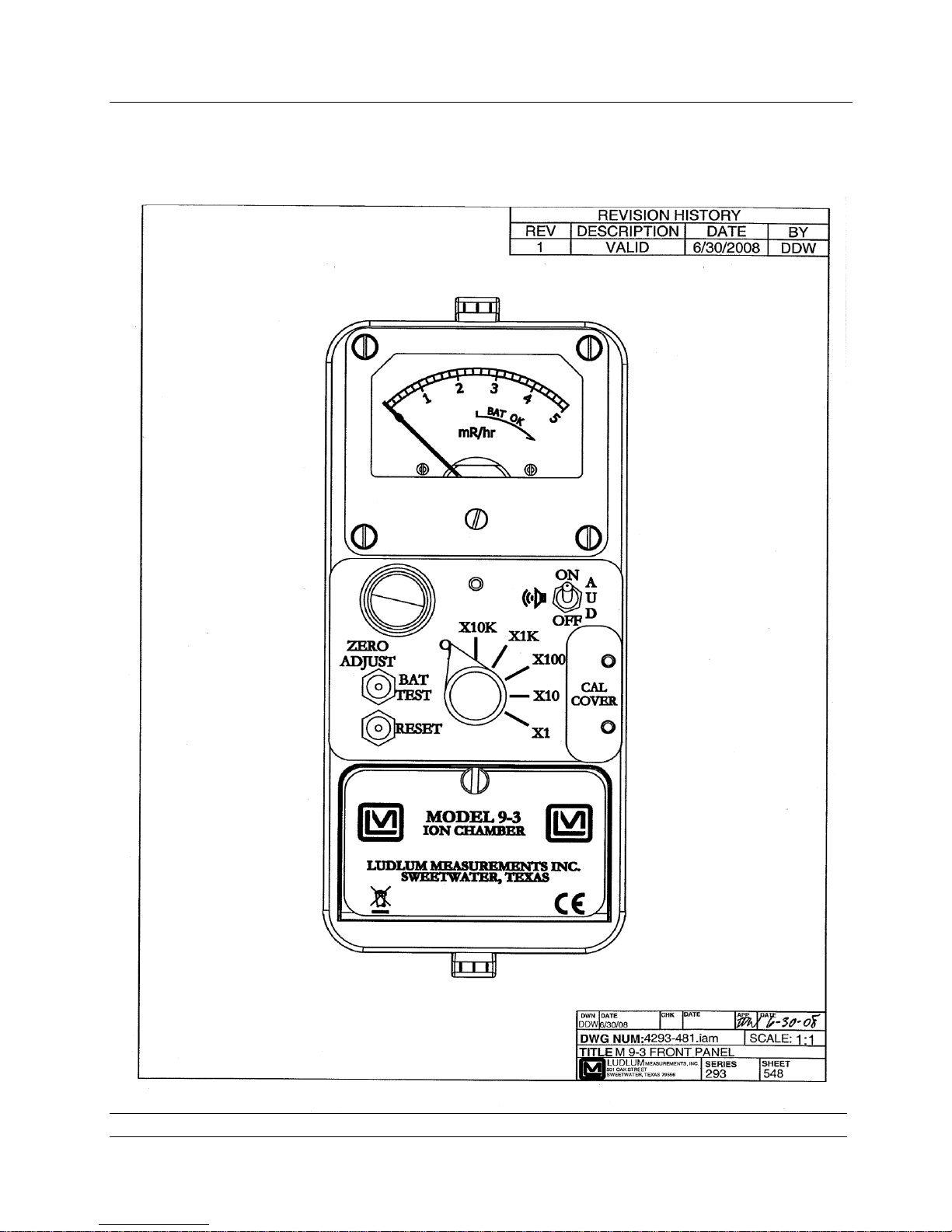
Range Selector Switch: This is a six-position switch marked OFF,
×10K, ×1K, ×100, ×10, and ×1. Turning the range selector switch from
OFF to one of the range multiplier positions (×10K, ×1K, ×100, ×10,
and × 1) provides the operator with an overall range of 0 to 50,000
mR/hr. Multiply the scale reading by the multiplier to determine the
actual scale reading.
BAT TEST: Press this switch to check the battery. The meter should read
within the BAT TEST scale on the meter. The range switch may be in
any position except OFF for the battery test.
AUD ON-OFF Toggle Switch: In the ON position, this switch energizes
the unimorph speaker, located on the left side of the instrument. The
frequency of the clicks is relative to the meter reading; the higher the
reading, the higher the audio frequency.
ZERO ADJUST: This is a full one-turn control that allows for
compensation of electrometer drift. Press and hold the RESET button
until the meter counts down, then adjust for a zero reading.
Range Calibration Adjustments: recessed potentiometers located under
the calibration cover, on the right side of the front panel. These
adjustment controls allow for individual calibration of each range
multiplier, and are labeled 1, 10, 100, 1K, and 10K
L: Recessed potentiometer located under the calibration cover; used to
adjust the meter to zero before the ZERO ADJUST is adjusted for a zero
meter reading with the RESET button depressed. Set range switch to
×100 and move the instrument to an area of low radiation and adjust L
for a meter reading of zero.
RESET Button: The RESET circuit discharges the chamber and opens the
chamber connection to the electrometer. This causes a transient on the ×1 and
×10 scales. The meter will indicate full scale and count-down for five seconds
Ludlum Measurements, Inc. Page 4-1 June 2018
Page 15

MODEL 9-3 Technical Manual Section 4
when the RESET switch is pressed and released. For near zero reading on ×1
scale, allow several more seconds for setting time after RESET is released
Beta Shield (on bottom): A retractable shield allowing exposure to beta
radiation with a window thickness of 7 mg/cm². With the slide closed,
the window is 1000 mg/cm². Depress the button on the side of the slide
assembly to release the slide. Release the button to hold the slide open
or closed.
Ludlum Measurements, Inc Page 4-2 June 2018
Page 16

MODEL 9-3 Technical Manual Section 5
Section
5
Safety Considerations and
Maintenance
Environmental Conditions for Normal Use
Indoor or outdoor use
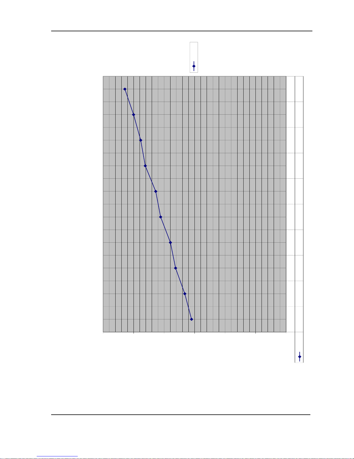
Altitude dependant: Response decreases 3% for every increase in 1000 feet of
elevation above the calibration elevation. (For further information, see the
Average Model 9 Altitude Dependence graph in Section 9 of this manual).
Temperature range of -20 to 50 °C (-4 to 122 °F)
Maximum relative humidity of less than 95% (non-condensing)
Pollution Degree 3 (as defined by IEC 664) (Occurs when conductive pollution
or dry nonconductive pollution becomes conductive due to condensation. This
is typical of industrial or construction sites.)
Warning Markings and Symbols
Caution!
The operator or responsible body is cautioned that the
protection provided by the equipment may be impaired if the
equipment is used in a manner not specified by Ludlum
Measurements, Inc.
The Model 9-3 Ion Chamber is marked with the
following symbols:
The “crossed-out wheelie bin” symbol notifies the consumer that the
product is not to be mixed with unsorted municipal waste when discarding;
each material must be separated. The symbol is placed on the battery
compartment lid. See section 7, “Recycling,” for further information.
Ludlum Measurements, Inc. Page 5-1 June 2018
Page 17

MODEL 9-3 Technical Manual Section 5
Warning!
The operator is strongly cautioned to take the following
precautions to avoid contact with internal hazardous live parts
that are accessible using a tool:
1. Turn the instrument power OFF and remove the batteries.
2. Allow the instrument to discharge before accessing internal
components. The 90-volt wall voltage will require several
hours to discharge. It may be discharged with a 10 megohm
resistor.
Metalized Polyester (Mylar)
Window Precaution
Caution!
Damage to the metalized polyester window on the back side of
the instrument may result if careful instrument handling is not
practiced. The window is very fragile and may be punctured
quite easily.
Cleaning and Maintenance Precautions
Instrument maintenance consists of keeping the instrument clean and
periodically checking the batteries, desiccants, and calibration. The Model 93 (excluding chamber window) may be cleaned externally with a damp cloth,
using only water as the wetting agent. Do not immerse the instrument in any
liquid. Observe the following precautions when cleaning or performing
maintenance on the instrument:
1. Turn the instrument OFF and remove the batteries.
2. Allow the instrument to sit for one minute before cleaning the
exterior or accessing any internal components for maintenance.
3. Discharge the wall voltage with a 10 megohm resistor, or allow
several hours for discharge if the instrument is opened.
Ludlum Measurements, Inc. Page 5-2 June 2018
Page 18

MODEL 9-3 Technical Manual Section 5
Maintenance
RECALIBRATION
Recalibration should be accomplished after maintenance or adjustments
have been performed on the instrument. Recalibration is not normally
required following instrument cleaning, desiccant servicing or battery
replacement
Note:
Ludlum Measurements, Inc. recommends recalibration at
intervals no greater than one year. Check the appropriate
regulations to determine required recalibration intervals.
Ludlum Measurements offers a full-service repair and calibration
department. We not only repair and calibrate our own instruments, but also
most other manufacturers’ instruments. Calibration procedures are available
upon request for customers who choose to calibrate their own instruments.
BATTERIES
The batteries should be removed any time the instrument is placed into
storage. Battery leakage may cause corrosion on the battery contacts, which
must be scraped off and/or washed using a paste solution made from
baking soda and water.
DESICCANT
Remove the instrument can and observe the translucent plastic desiccant
box. If the desiccant is blue, close the can and use the instrument. If the
desiccant is pink, replace with a fresh box. The restraining strap may be
loosened by pressing the center tab toward the strap.
The pink (wet) desiccant may be recycled by placing it in an oven at 55 °C
(131 °F) for two hours, or in a microwave on the HI setting for 10 seconds.
If water vapor is apparent, wipe off the water and heat for another 10
seconds. Repeat until the box and desiccant appear dry. When fully dried
out, the desiccant will be blue in color.
Ludlum Measurements, Inc. Page 5-3 June 2018
Page 19

MODEL 9-3 Technical Manual Section 5
Caution!
The desiccant box will be HOT when removed from the
microwave or oven!
If the instrument is stored in an area with high humidity, rapid changes in
temperature should be avoided. A storage cabinet with a light bulb inside is
one means of keeping the instrument in a slightly warmer than ambient
temperature environment, in order to prevent problems from rapid changes
in temperature and humidity.
Return for Repair or Calibration
To return an instrument for repair or recalibration, provide sufficient
Return Form, which can be downloaded from the Ludlum website at
www.ludlums.com. Find the form by clicking the “Support” tab and
selecting “Repair and Calibration” from the drop-down menu. Then choose
the appropriate Repair and Calibration dvision where you will find a link to
the form.
Ludlum Measurements, Inc. Page 5-4 June 2018
Page 20

MODEL 9-3 Technical Manual Section 6
Section
6
Technical Theory of Operation
Chamber
The chamber housing is constructed from acrylic and is coated inside and
outside with carbon. The internal wall is maintained at approximately 90
volts. The external wall is at ground potential.
The electrode is connected to the electrometer input and is maintained at
ground potential by the electrometer.
Chamber Window
The chamber window consists of three parts. The beta shield is 1000
mg/cm² phenolic. One layer of 3.5 mg/cm² metallized polyester is glued to
the bottom of the can and one layer of 3.5 mg/cm² metalized polyester
covers the ion chamber, resulting in a window thickness of 7 mg/cm² with
the beta slide open, and a 1000 mg/cm2 window with the beta slide closed.
Electrometer
The electrometer consists of U1, R2, and supporting components. On
the ×1 scale, RL1 and RL2 are open. With conduction in the chamber to
the negative wall, pin 8 of U1 goes slightly negative causing pin 4 of U1
to go positive, drawing current through R2, holding pin 8 of U1 near the
guard voltage (+1.5 volts).
With the chamber exposed to a 5 mR/hr field, the chamber current will
be approximately 70 fA (70 x 10
voltage will be 35 mV (0.035 V) relative to the guard voltage. At 50
mR/hr on the x10 range, the output voltage will be 350 mV (0.35 V)
relative to the guard voltage.
-15
amps) and electrometer output
Ludlum Measurements, Inc. Page 6-1 June 2018
Page 21

MODEL 9-3 Technical Manual Section 6
Range Change
When the instrument is switched to the ×100, ×1K, or ×10K range,
RL1 is closed, reducing the feedback resistance to approximately 4.2 x
109 ohms. At 500 mR/hr on the x100 range, the chamber current will be
approximately 7 pA (7 x 10
will be approximately 30 mV (0.03 V). Full-scale voltage outputs relative
to the guard voltage for the x1K and x10K are 300 mV (0.3 V) and 3 V
respectively.
-12
amps) and the voltage out at pin 6 of U1
Reset
Relay RL2 allows the chamber to be shorted to ground and the electrometer
to be isolated for input bias current compensation. The reset switching
transient lasts about five seconds. When the RESET button is pressed, the
meter will read full scale, and then count down for five seconds. When
released, the countdown will begin again. The countdown function occurs
on the ×1 and ×10 scales.
Offset Adjustment
The electrometer op amp will have some offset voltage. Control L (R60)
will provide an offset voltage that can be adjusted to null out the
electrometer offset voltage. Select ×100 scale and adjust L for zero meter
reading.
Zero Adjust
The primary function of the zero adjust is to control input bias current in the
electrometer. With the RESET (SW2) closed, the reset relay (RL2) opens the
electrometer input and shorts the chamber output to ground. With the
RESET held closed, input bias current is adjusted with the zero control for a
zero meter dial reading.
Note:
Allow a five-second recovery period for the meter to settle
when the RESET button is closed, and a 15-second recovery
to settle when opened
Ludlum Measurements, Inc. Page 6-2 June 2018
Page 22

MODEL 9-3 Technical Manual Section 6
Range Calibration
For full-scale voltage for the electrometer output, pin 4 of U1 (electrometer
board 5293-442) is approximately +0.03 volts for the ×1 range; 0.3 volts for
the ×10 range; +0.025 volts for the ×100; and +0.025 volts for the ×1K
range. The ×10K range will be somewhat lower than +2.5 volts due to
nonlinear collection.
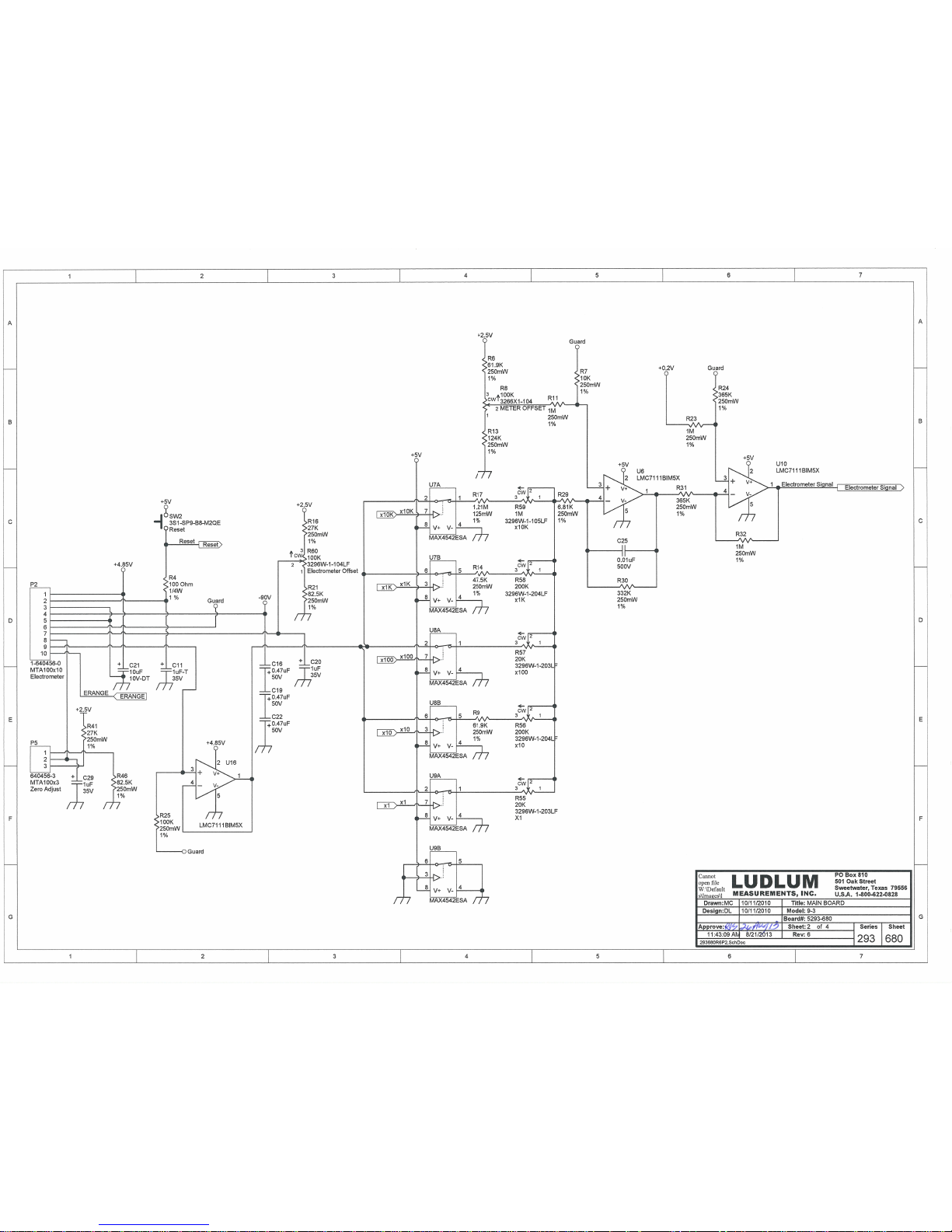
On the ×1 scale, the electrometer voltage is coupled through voltage
follower U16 to the analog switch U9A to a series of op amps. U6 provides
gain; U10 provides gain and reduces the output and reference from guard
voltage to 0.2 volts. With voltage output at pin 1, U10 is approximately two
volts at full scale. Higher scales follow the same scheme through the analog
switches selected by the range switch.
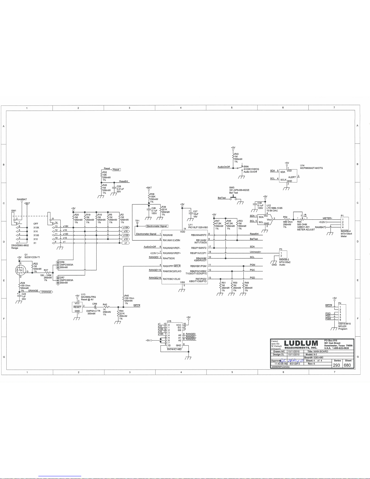
The output voltage of U10 is connected to microprocessor U11, which
allows calibration and temperature correction.
The signal reference voltage is 0.2 volts at the output of digital analog
converter U12, allowing a below zero meter reading when adjusting the zero
control.
Internal calibration control R60 is utilized to set the meter reading at zero
with the electrometer disconnected.
Internal calibration control R35 is utilized to calibrate full scale signal for the
reset countdown.
Range Changing
The microprocessor U110 detects the selected range and then selects the
appropriate analog switch (U7A, U7B, U8A, U8B, or U9A) for the signal.
A calibration constant is then provided by the microprocessor for each
range.
In the special case of ×10K scale, the microprocessor also provides a
linearity correction.
Power Supplies
Six voltages are provided for instrument operation.
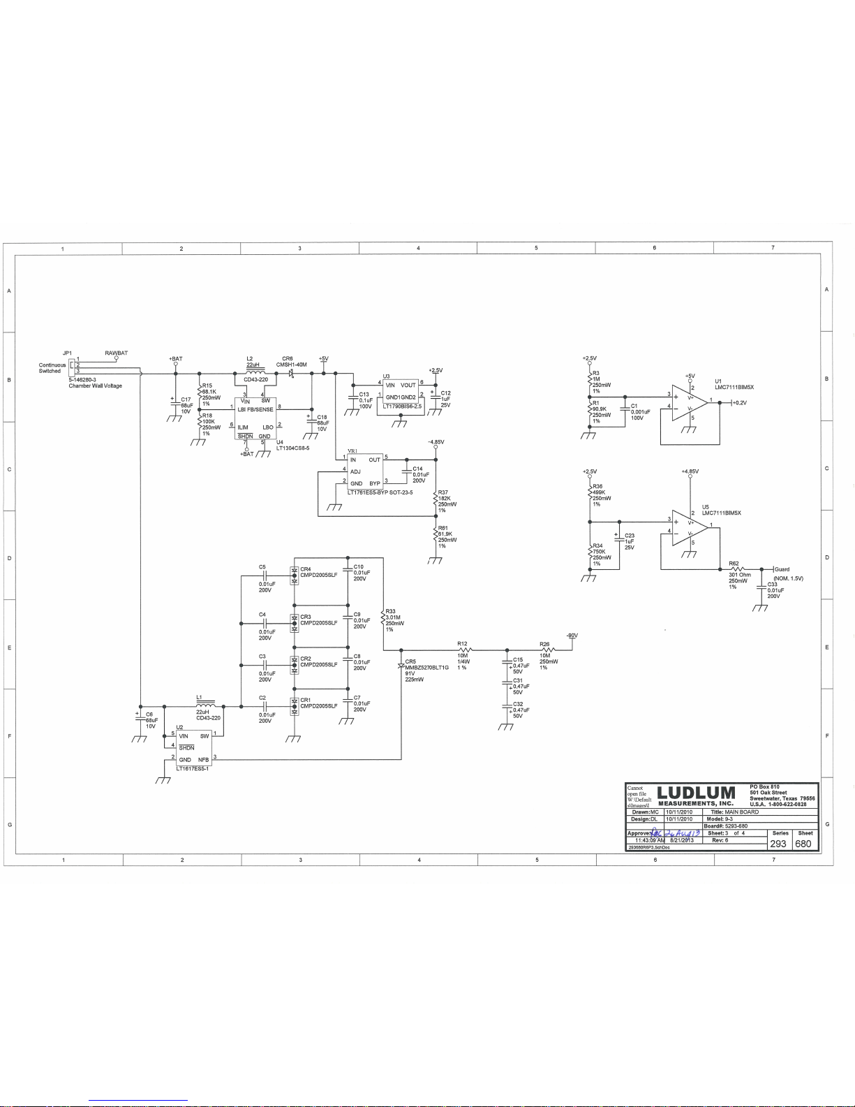
U2 and associated components generate -90 volts for chamber wall voltage.
The supply will run continually with the instrument off if the jumper is
placed between pins 1 and 2 of JP1. If the operator chooses to have wall
voltage off with the instrument switched off, then the jumper should be
moved to pins 2 and 3 of JP1.
Ludlum Measurements, Inc. Page 6-3 June 2018
Page 23

MODEL 9-3 Technical Manual Section 6
U4 and associated components generate +5 volts for the main board
circuits.
U3 provides a regulated +2.5-volt reference.
VR1 provides +4.85 volts for the electrometer.
U5 and associated components provides a 1.5-volt guard voltage for the
electrometer.
U1 provides meter reference of 0.2 volts.
Audio Circuit
Microprocessor U11, in conjunction with unimorph DS1, converts the
analog output signal to an audio signal. A series of audio clicks will increase in
frequency as the output voltage increases. The audio may be turned on or off
by SW4.
Meter Circuit
Microprocessor U11 is connected to DA converter U12 to drive the meter
movement. R35 is adjusted for the reset countdown to start at full scale (5)
on the ×1 scale.
Ludlum Measurements, Inc. Page 6-4 June 2018
Page 24

MODEL 9-3 Technical Manual Section 7
Section
7
L
Recycling
udlum Measurements, Inc. supports the recycling of the electronics
products it produces for the purpose of protecting the environment
and to comply with all regional, national, and international agencies
that promote economically and environmentally sustainable
recycling systems. To this end, Ludlum Measurements, Inc. strives to supply
the consumer of its goods with information regarding reuse and recycling of
the many different types of materials used in its products. With many
different agencies – public and private – involved in this pursuit, it becomes
evident that a myriad of methods can be used in the process of recycling.
Therefore, Ludlum Measurements, Inc. does not suggest one particular
method over another, but simply desires to inform its consumers of the
range of recyclable materials present in its products, so that the user will
have flexibility in following all local and federal laws.
The following types of recyclable materials are present in Ludlum
Measurements, Inc. electronics products and should be recycled separately.
The list is not all-inclusive, nor does it suggest that all materials are present in
each piece of equipment:
Batteries Glass Aluminum and Stainless Steel
Circuit Boards Plastics Liquid Crystal Display (LCD)
Ludlum Measurements, Inc. products, which have been placed on the
market after August 13, 2005, have been labeled with a symbol recognized
internationally as the “crossed-out wheelie bin.” This notifies the consumer
that the product is not to be mixed with unsorted municipal waste when
discarding; each material must be separated. The symbol will be placed near
the AC receptacle, except for portable equipment where it will be placed on
the battery lid.
The symbol appears as such:
Ludlum Measurements, Inc. Page 7-1 June 2018
Page 25

MODEL 9-3 Technical Manual Section 8
Section
8
Model 9-3 Ion
Chamber
Main Circuit Board,
Drawing 293 × 680
CAPACITORS
Parts List
Reference Description Part Number
UNIT Completely Assembled
Model 9-3 Ion Chamber 48-3633
BOARD Completely Assembled
Main Circuit Board 5293-680
C1 0.001uF, 100V 04-5659
C2-C5 0.01uF, 200V 04-5765
C6 68uF, 10V 04-5654
C7-C10 0.01uF, 200V 04-5765
C11 1uF, 35V 04-5656
C12 1uF, 25V-T 04-5822
C13 0.1uF, 100V 04-5792
C14 0.01uF, 200V 04-5765
C15, C16 0.47uF, 50V 04-5760
C17, C18 68uF, 10V 04-5654
C19 0.47uF, 50V 04-5760
C20 1uF, 35V 04-5656
C21 10uF, 10V-DT 04-5766
C22 0.47uF, 50V 04-5760
C23 1uF, 25V-T 04-5822
C24 1uF, 35V 04-5656
C25 0.01uF, 500V 04-5747
Ludlum Measurements, Inc. Page 8-1 June 2018
Page 26

MODEL 9-3 Technical Manual Section 8
CAPACITORS
TRANSISTORS
INTEGRATED
CIRCUITS
DIODES
POTENTIOMETER
Reference Description Part Number
C26 0.1uF, 100V 04-5792
C27 10uF, 10V 04-5757
C28 0.01uF, 50V 04-5664
C29 1uF, 35V 0 4-5656
C30 0.1uF, 100V 04-5792
C30 0.1uF, 100V 04-5792
C31, C32 0.47uF, 50V 04-5760
Q1 SI2301BDS-TI 07-6486
U1 LMC7111BIM5X 06-6410
U2 LT1617ESS-1 06-6760
U3 LT1790BIS6-2.5 06-6691
U4 LT1304CS8-5 06-6434
U5- U6 LMC7111BIM5X 06-6410
U7- U9 MAX4542ESA 06-6453
U10 LMC7111BIM5X 06-6410
U11 PIC18LF1320-I/SO 06-6709
U12 LTC1669-1CS5 06-6657
U13 MAX809JTRG 06-6423
U14 MCP9800AOT-M/OTG 06-6687
U15 SN74HC148D 06-6765
U16 LMC7111BIM5X 06-6410
CR1-CR4 CMPD2005SLF 07-6468
CR5 MMBZ5270BLT1G 07-6474
CR6 CMSH1-40M 07-6411
CR7, CR8 CMPD3003A 07-6498
CR9 CMPSH-3 TR 07-6489
CR6-CR7 CMPD3003A 07-6498
R8 100K, 3266X1-104, Meter Offset 09-6823
R35 500Ohm, 3266X1-501, Meter Adj 09-6848
R55 20K, 3296W-1-203LF, X1 X100 09-6835
R56 200K, 3296W-1-204LF, X1K,X10 09-6964
R57 20K, 3296W-1-203LF, X1 X100 09-6835
R58 200K, 3296W-1-204LF, X1K,X10 09-6964
R59 1M, 3296W-1-105LF, X10K 09-6814
R60 100K, 3296W-1-104LF, Elec Off 09-6813
Ludlum Measurements, Inc. Page 8-2 June 2018
Page 27

MODEL 9-3 Technical Manual Section 8
RESISTORS
Reference Description Part Number
R1 90.9K, 250mW, 1% 12-7224
R2, R3 1M, 250mW, 1% 12-7844
R4 100Ohm, 250mW, 1% 12-7840
R5 1M, 250mW, 1% 12-7844
R6 61.9K, 250mW, 1% 12-7026
R7 10K, 250mW, 1% 12-7844
R9 47.5K, 250mW, 1% 12-7872
R10, R11 1M, 250mW, 1% 12-7844
R12 10M, 250mW, 1% 12-7996
R13 124K, 250mW, 1% 12-7032
R14 47.5K, 250mW, 1% 12-7872
R15 68.1K, 250mW, 1% 12-7881
R16 27K, 250mW, 1% 12-7243
R17 750K, 250mW, 1% 12-7882
R18 100K, 250mW, 1% 12-7834
R19, R20 1M, 250mW, 1% 12-7844
R21 82.5K, 250mW, 1% 12-7849
R22, R23 1M, 250mW, 1% 12-7844
R24 365K, 250mW, 1% 12-7049
R25 100K, 250mW, 1% 12-7834
R26 10M, 250mW, 1% 12-7996
R27 10K-100K, 250mW, 1% 12-7844
R28 100Ohm, 250mW, 1% 12-7840
R29 4.02K, 250mW, 1% 12-7006
R30 332K, 250mW, 1% 12-7976
R31 365K, 250mW, 1% 12-7049
R32 1M, 250mW, 1% 12-7844
R33 3.01M, 250mW, 1% 12-7209
R34 750K, 250mW, 1% 12-7882
R36 499K, 250mW, 1% 12-7037
R37 182K, 250mW, 1% 12-7860
R38 100K, 250mW, 1% 12-7834
R39 221K, 250mW, 1% 12-7845
R40 100Ohm, 250mW, 1% 12-7840
R41 27K, 250mW, 1% 12-7243
R42 1K, 250mW, 1% 12-7832
R43 1M, 250mW, 1% 12-7844
R44 221K, 250mW, 1% 12-7845
R45 1M, 250mW, 1% 12-7844
R46 82.5K, 250mW, 1% 12-7849
R47, R48 47.5K, 250mW, 1% 12-7872
R49-R51 1M, 250mW, 1% 12-7844
Ludlum Measurements, Inc. Page 8-3 June 2018
Page 28

MODEL 9-3 Technical Manual Section 8
CONNECTORS
VOLTAGE
REGULATORS
SWITCHES
INDUCTORS
Electrometer Board, Drawing
293 × 670
CAPACITORS
INTEGRATED
CIRCUIT
DIODES
RESISTORS
RELAYS
Reference Description Part Number
R52 10K, 250mW, 1% 12-7839
R53 1M, 250mW, 1% 12-7844
R54 499 Ohm, 250mW, 1% 12-7907
R61 61.9K, 250mW, 1% 12-7026
P1 640456-4 MTA100×4 13-8088
P2 1-640456-0 MTA100×10 13-8066
P3 640456-2 MTA100×2 13-8073
P4 53014-0610Molex 13-8974
P5 640456-3 MTA100×3 13-8081
JP1 5-146280-3Cham Wall Volt 13-8571
VR1 LT1761ES5-BYP 06-6662
SW1 D5G0206S-9802 Range 08-6761
SW2, SW3 3SI-SP9-B8-M2QE Bat Test 7464-186
SW4 A123S1CWCQ Audio On-Off 08-6781
L1, L2 22µH 21-9808
BOARD Completely Assembled
Electrometer Board 5293-670
C1 2pF, 200V 04-5726
U1 IC-LMP7721MA 06-6728
CR1-CR2 CMPSH-3 07-6489
R1 1M, 1/4W, 1% 12-7844
R2 500G, 330 mW, 20% 12-7248
R3 4.2G, 5% 12-7249
R6 169K, 0.25W, 1% 12-8008
R7 500G, 330 mW, 20% 12-7248
R8 1M, 1/4W, 1% 12-7844
R9 100K, 1/4W, 1% 12-7834
RL1 SPST-NC 4293-339
4293-541
RL2 SPDT 08-6845
4293-538
Ludlum Measurements, Inc. Page 8-4 June 2018
Page 29

MODEL 9-3 Technical Manual Section 8
CONNECTORS
Wiring Diagram 293 × 525
AUDIO
MISCELLANEOUS
P1 1-640456-0 MTA100 13-8066
P2 103186-1 13-8471
DS1 UNIMORPH SPEAKER 60690 21-9251
* Model 9-3 Casting Assy (AA) 4293-490
* Model 9-3 Pushbutton Can Assy 4293-506
* Model 9-3 Chamber Assy 4293-521
* Portable Bezel with
Movement Assembly 4363-188
* Can Mylar Window 7293-792
* Chamber Window Assembly 4293-500
* Portable Handle (Rolled) 4464-154
* Model 9-3 Chamber Top Co-Netic Shield
7536-223
* Model 9-3 Chamber Top Netic Shield
7536-224
Ludlum Measurements, Inc. Page 8-5 June 2018
Page 30

MODEL 9-3 Technical Manual Section 9
Section
9
Drawings
AVERAGE MODEL 9 ALTITUDE DEPENDENCE
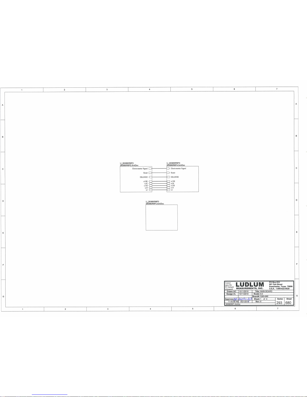
MAIN BOARD SCHEMATIC, Drawing 293 × 680 (4 Sheets)
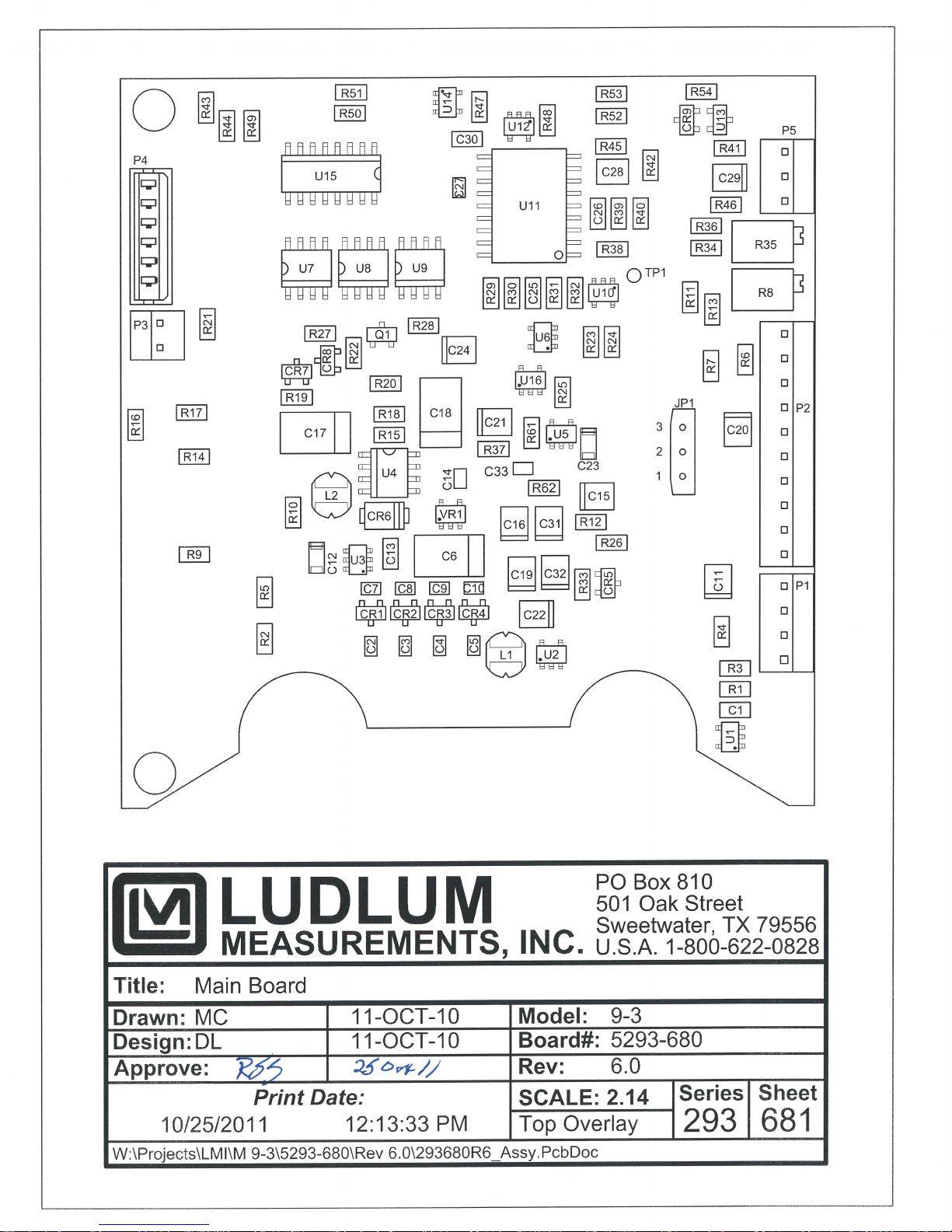
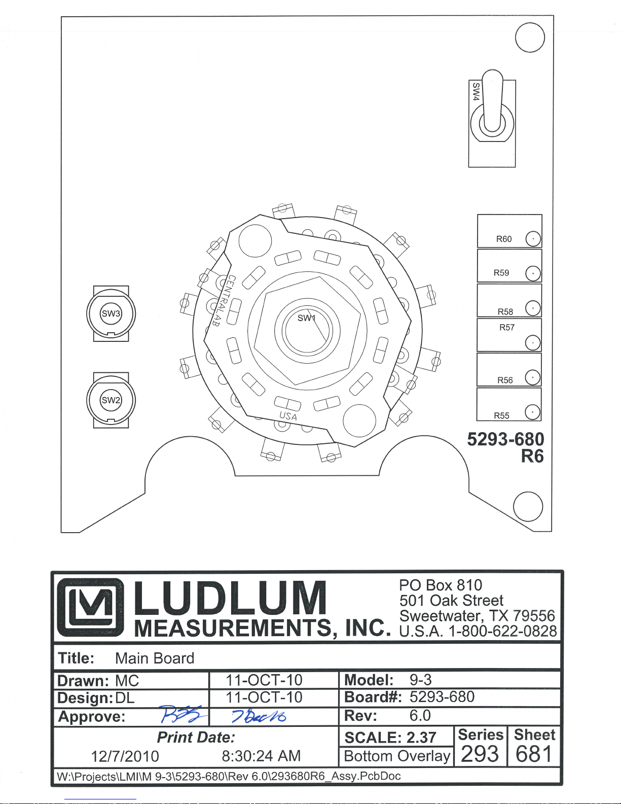
MAIN BOARD LAYOUT, Drawing 293 × 681 (2 Sheets)
ELECTROMETER BOARD, Drawing 293 × 670
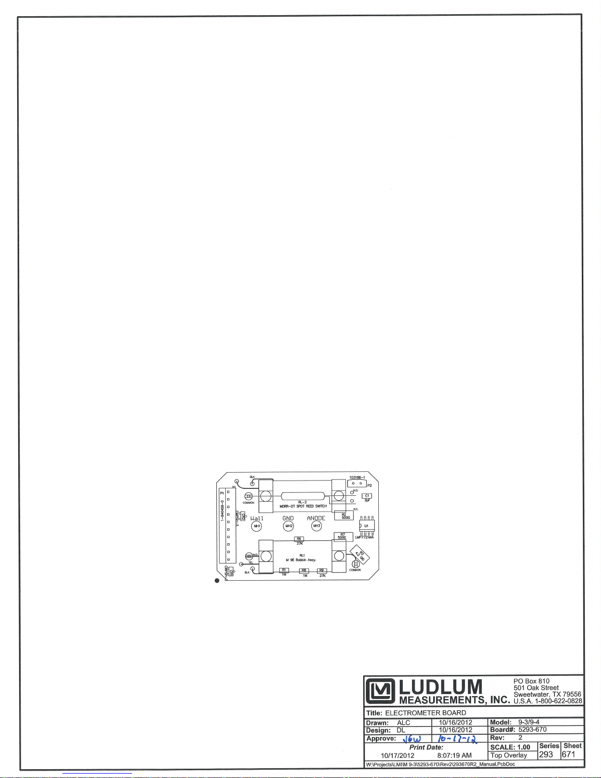
ELECTROMETER BOARD OVERLAY Drawing 293 × 671
WIRING DIAGRAM, Drawing 293 × 525
Ludlum Measurements, Inc. Page 9-1 June 2018
Page 31
MODEL 9-3 Technical Manual Section 9
AVERAGE MODEL 9 ALTITUDE DEPENDANCE
0%
20%
40%
60%
80%
100%
120%
Altitude in Feet
Series1
Series1
62%
66%
72%
76%
82%
85%
92%
95%
100%
106%
15000
14000
12000
10000
8000
6000
5000
3000
2000
0
Ludlum Measurements, Inc June 2018
Page 32
Page 33
Page 34
Page 35
Page 36
Page 37
Page 38
Page 39
Page 40

 Loading...