


LUDLUM MODEL 3030 & 3030E SERIES
ALPHA-BETA SAMPLE COUNTER
November 2017
Serial Number 185762 and Succeeding
Serial Numbers

LUDLUM MEASUREMENTS, INC.
501 OAK STREET, P.O. BOX 810
SWEETWATER, TEXAS 79556
325-235-5494, FAX: 325-235-4672
LUDLUM MODEL 3030 & 3030E SERIES
ALPHA-BETA SAMPLE COUNTER
November 2017
Serial Number 185762 and Succeeding
Serial Numbers

STATEMENT OF WARRANTY
Ludlum Measurements, Inc. warrants the products covered in this manual to be free
of defects due to workmanship, material, and design for a period of twelve months
from the date of delivery. The calibration of a product is warranted to be within its
specified accuracy limits at the time of shipment. In the event of instrument failure,
notify Ludlum Measurements to determine if repair, recalibration, or replacement is
required.
This warranty excludes the replacement of photomultiplier tubes, G-M and
proportional tubes, and scintillation crystals which are broken due to excessive
physical abuse or used for purposes other than intended.
There are no warranties, express or implied, including without limitation any implied
warranty of merchantability or fitness, which extend beyond the description of the
face there of. If the product does not perform as warranted herein, purchaser’s sole
remedy shall be repair or replacement, at the option of Ludlum Measurements. In no
event will Ludlum Measurements be liable for damages, lost revenue, lost wages, or
any other incidental or consequential damages, arising from the purchase, use, or
inability to use product.
RETURN OF GOODS TO MANUFACTURER
If equipment needs to be returned to Ludlum Measurements, Inc. for repair or calibration, please
send to the address below. All shipments should include documentation containing return shipping
address, customer name, telephone number, description of service requested, and all other necessary
information. Your cooperation will expedite the return of your equipment.
LUDLUM MEASUREMENTS, INC.
ATTN: REPAIR DEPARTMENT
501 OAK STREET
SWEETWATER, TX 79556
800-622-0828 325-235-5494
FAX 325-235-4672


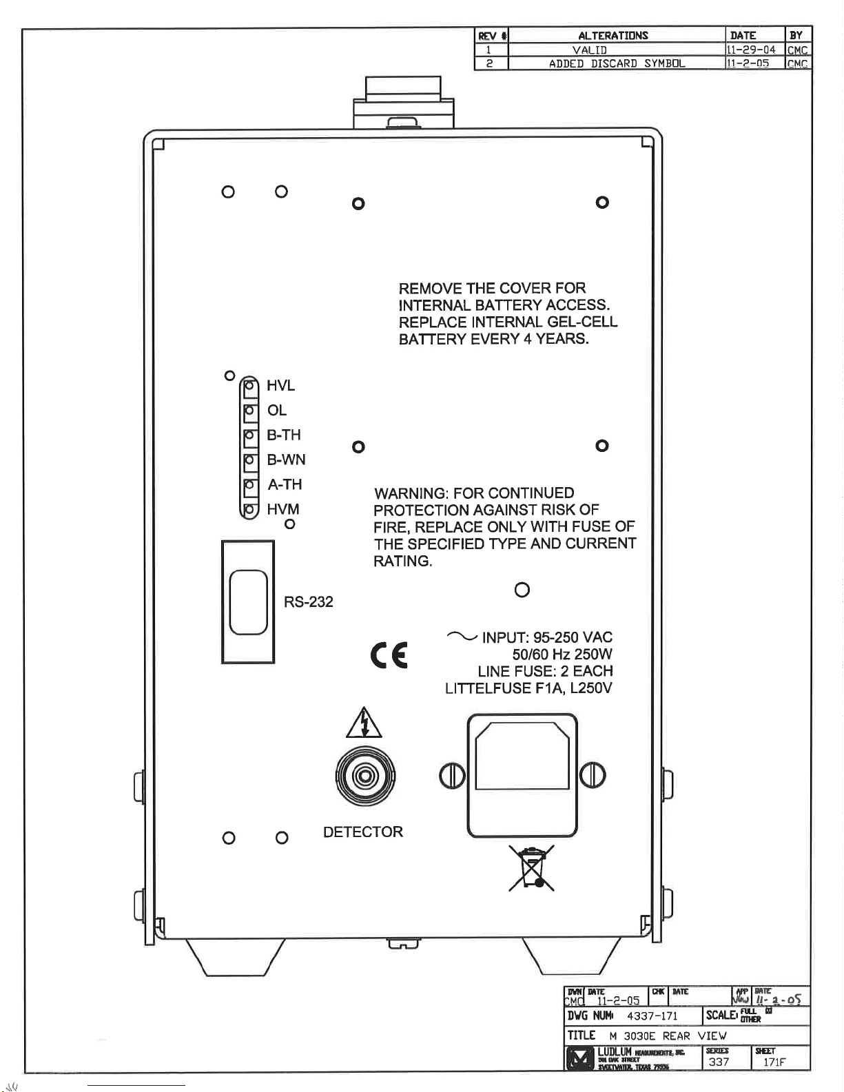


Table of Contents
INTRODUCTION ............................................................................................................. 1
GETTING STARTED ...................................................................................................... 3
Unpacking and Repacking .......................................................................................................................................... 3
Software Installation ................................................................................................................................................... 4
External Counter HV Connector (3030E only) ......................................................................................................... 4
Start-up ................................................................................................ ................................................................ ......... 4
SPECIFICATIONS .......................................................................................................... 6
Model 3030 ONLY .............................................................................................................................................. 6
Model 3030E ONLY ............................................................................................................................................ 6
Common Specifications ....................................................................................................................................... 7
DESCRIPTION OF CONTROLS AND FUNCTIONS ...................................................... 8
Front Panel ................................................................................................................................................................... 8
Back Panel .................................................................................................................................................................... 9
Internal Controls ....................................................................................................................................................... 10
SAFETY CONSIDERATIONS ....................................................................................... 11
Environmental Conditions for Normal Use ............................................................................................................. 11
Cleaning Instructions and Precautions .................................................................................................................... 11
Warning Markings and Symbols ............................................................................................................................. 12
Replacement of Main Fuse (Back Panel) ................................................................................................................. 13
CALIBRATION AND MAINTENANCE ......................................................................... 14
Calibration ................................................................................................................................................................. 14
Recommended Sources ............................................................................................................................................ 14
Calibration Procedure ............................................................................................................................................... 14
Maintenance ................................ ................................................................ ............................................................... 18
COMPUTER SOFTWARE ............................................................................................ 20
Parameters ................................................................................................................................................................. 22

QC Check ................................................................................................................................................................... 25
HV Plateau ................................................................................................................................................................. 29
MDA Calculations ..................................................................................................................................................... 32
Data Logging .............................................................................................................................................................. 33
RS-232 Communication ............................................................................................................................................ 34
COMMANDS ............................................................................................................................................................. 34
Bn – Background Subtract Status ............................................................................................................................. 34
Cn – Count ............................................................................................................................................................... 35
Dn – Display Mode .................................................................................................................................................. 35
F – Firmware ............................................................................................................................................................ 35
Ln – Logging Mode .................................................................................................................................................. 35
Pn .............................................................................................................................................................................. 35
Qx ............................................................................................................................................................................. 35
RA – Read Next Sample Number............................................................................................................................. 36
RBn – Read Background Subtract ............................................................................................................................ 36
RC – Read Calibration Due Date ............................................................................................................................. 36
RD – Read Current Date and Time .......................................................................................................................... 36
REn – Read Efficiency ............................................................................................................................................. 36
RHn – Read Header .................................................................................................................................................. 36
RL – Read Loss of Count Timer .............................................................................................................................. 36
RNn – Read MDA .................................................................................................................................................... 36
RP – Read the PC Time ............................................................................................................................................ 37
RQn .......................................................................................................................................................................... 37
RR – Read Count ...................................................................................................................................................... 37
RS – Read Samples .................................................................................................................................................. 38
RT – Read Current Count Time ............................................................................................................................... 38
RU – Read Comment ............................................................................................................................................... 38
RV – Read High Voltage .......................................................................................................................................... 38
RXn – Read the Crosstalk ........................................................................................................................................ 38
RY – Read Recycle Mode Status ............................................................................................................................. 38
Rn – Read the Alarm Set Points ............................................................................................................................... 38
Xn – Set Crosstalk Mode .......................................................................................................................................... 39
SBnxxxxxx – Set Background Subtract ................................................................................................................... 39
SCmmddyyyy – Set Calibration Date ...................................................................................................................... 39
SDmmddyyyyz – Set Date ....................................................................................................................................... 39
SEnxxx – Set Efficiency ........................................................................................................................................... 39
SHnxxxxxxxxxxxxxxx – Set Header ....................................................................................................................... 39
SLyyyyy.y – Set Loss of Count Timer ..................................................................................................................... 39
SNnyyyyyy – Set MDA............................................................................................................................................ 39
SPxxxxx.x ................................................................................................................................................................ 40
SQnn – Set QC parameters ....................................................................................................................................... 40
SR – Reset All Samples ............................................................................................................................................ 40
SThhmm – Set Time ................................................................................................................................................. 40
SUxxxxxxxxxx – Set Command .............................................................................................................................. 40
SVxxxx – Set High Voltage ..................................................................................................................................... 40
SXnyyy – Set Crosstalk ............................................................................................................................................ 41
SYn – Set Recycle Mode .......................................................................................................................................... 41
Snxxxxxx – Set Alarm ............................................................................................................................................. 41

Sample Printouts........................................................................................................................................................ 41
Software License Agreement .................................................................................................................................... 43
RECYCLING ................................................................................................................. 46
PARTS LIST ................................................................................................................. 47
Model 3030 & Model 3030E Alpha-Beta Sample Counters .............................................................................. 47
Amplifier / Processor Board, Drawing 337 × 189 .............................................................................................. 47
Display Board, Drawing 337 × 88 ..................................................................................................................... 50
Power Supply Board, Drawing 337 × 133 ......................................................................................................... 51
Wiring Diagram, Drawing 337 × 182 ................................................................................................................ 51
Model 3030 ONLY ............................................................................................................................................ 52
DRAWINGS AND DIAGRAMS ..................................................................................... 53
MODEL 3030-2 ........................................................................................................... A-1

Model 3030 & 3030E Series Technical Manual Section 1
Section
1
T
Introduction
he Model 3030 and 3030E are dual-channel counters designed for
simultaneous alpha and beta sample measurement. The Model 3030
has a built-in scintillation detector with a shielded chamber and
chrome-plated brass sample tray that can accept a maximum sample
size of 5.1 cm (2 in.) in diameter. The Model 3030E utilizes an external, side
mounted sample counter. Common external counters are: the alpha-only,
Model 43-10, or the alpha-beta, Model 43-10-1. Throughout this manual, the
term “3030” will be used to refer to both instruments unless otherwise
noted.
The Model 3030 is powered by main supply of 95-250 Vac. The instrument
features a built-in detector, high-voltage power supply, adjustable count time
periods, and a click-per-event audio with adjustable volume. A pulse height
analyzer is employed to provide information to the two independent
counters. The Model 3030 also features an internal trickle-charged gel-cell
battery for providing up to eight hours of use without mains supply. The
two independent LCDs (liquid crystal displays) feature six 1.3 cm (0.5 in.) tall
digits, which are backlit for improved visibility.
The instrument may be operated as a traditional scaler (counts per count
time) with a manually adjustable high voltage, or may be enabled to operate
with advanced features. The 9-pin RS-232 connector on the back of the
instrument allows attachment to a computer or printer. Software is provided
to allow the setup of several advanced features.
The counts per minute (CPM) or disintegrations per minute (DPM) modes
may be enabled to allow the count to be converted (automatically, in real
time) to cpm or dpm. The background radiation count may be subtracted
automatically in either mode. Crosstalk correction, alpha or beta alarms, and
time/date may also be set. Parameters are stored in non-volatile memory.
Time and date are maintained with an internal lithium battery.
Another advanced feature, which may be enabled or disabled, is the QC
Ludlum Measurements, Inc. Page 1 November 2017
(Quality Control) check function. When enabled, the user must perform

Model 3030 & 3030E Series Technical Manual Section 1
measurements on known sources (and background) and receive acceptable
numbers in order for the instrument to be used that day. Twenty-four hours
later, the QC LED (light emitting diode) is turned on, indicating the need for
another QC check. This feature ensures that the instrument is tested daily
and that measurements are valid.
The Model 3030-2 is a variant of the Model 3030 that allows the count to be
displayed in units of Bq or CPS (counts per second). In order to do this, the
status light for overload (OL) is changed to a green indicator, and the
overload condition is instead displayed as "OL" on both LCD displays. The
final change is that, when placed into Bq or CPS units, the alpha and beta
LCD displays are changed to having a second decimal point, ie. in the
format xxxx.xx to allow for lower-level measurements. The Model 3030-2
does have a distinctly different front panel that has the model number
"3030-2" prominently displayed. A detailed summary of these changes are
found in Appendix A, starting with page A-1.
The Model 3030E-2 is like the Model 3030-2, but with an external detector
like the Model 3030E.
Ludlum Measurements, Inc. Page 2 November 2017

Model 3030 & 3030E Series Technical Manual Section 2
Section
2
Getting Started
Unpacking and Repacking
Caution
The Model 3030 Alpha-Beta Scaler weighs approximately 13.2
kg (29 lb). Take necessary precautions when lifting the
instrument to prevent personal injury or strain.
Remove the calibration certificate and place it in a secure location. Remove
the instrument and accessories (batteries, cable, etc.) and ensure that all of
the items listed on the packing list are in the carton. Check individual item
serial numbers and ensure calibration certificates match. The Model
3030/3030E serial number is located on the back panel, lower left-hand
corner. Most Ludlum Measurements, Inc. detectors have a label on the base
or body of the detector for model and serial number identification.
Important!
If multiple shipments are received, ensure that the detectors
and instruments are not interchanged (particularly in the case
of the Model 3030E). Each instrument is calibrated to a
specific detector(s), and is therefore not interchangeable.
To return an instrument for repair or calibration, provide sufficient packing
material to prevent damage during shipment. Also provide appropriate
warning labels to ensure careful handling.
Every returned instrument must be accompanied by an Instrument Return
Form, which can be downloaded from the Ludlum website at
www.ludlums.com. Find the form by clicking the “Support” tab and
selecting “Repair and Calibration” from the drop-down menu. Then choose
the appropriate Repair and Calibration division where you will find a link to
the form.
Ludlum Measurements, Inc. Page 3 November 2017

Model 3030 & 3030E Series Technical Manual Section 2
Software Installation
Interface software supplied with the instrument will need to be installed if
access to advanced features is desired. User must comply with the software
license agreement found in Section 7 of this manual.
Install the Model 3030 interface software before making any connections
between the instrument and a computer.
Note:
Uninstall any previous version of the Model 3030 interface
software prior to installing this version.
Place the CD in the computer CD drive. The software will automatically
install. If desired, double-click “setup.exe” to manually install the software.
After the automatic installation program begins, follow the prompts. Take
note of the directory to which the executable file is saved. After completion
of the installation, the program may be accessed through the directory in
which it was saved.
External Counter HV Connector (3030E only)
Caution!
The external counter operating voltage (HV) is supplied to the
counter via the counter input connector. A mild electric shock
may occur if bodily contact is made with the center pin of the
input connector. Switch to OFF before connecting or dis-
connecting the cable or counter.
Connect one end of a counter cable to the counter by firmly pushing the
connectors together while twisting clockwise a quarter of a turn. Repeat the
process in the same manner with the other end of the cable and the
instrument.
Start-up
Before using the instrument for the very first time, determine whether or not
a computer interface is desired. If the computer interface is desired, revert to
the previous subsection, “Software Installation,” before continuing, and then
connect the instrument to the computer using the RS-232 cable provided.
Ludlum Measurements, Inc. Page 4 November 2017

Model 3030 & 3030E Series Technical Manual Section 2
Connect the instrument to mains power using the power cable provided and
then turn the instrument on “|” using the front panel power switch (lower
left corner).
Upon power-up, the LCD displays become backlit, front panel indicators
(LEDs) illuminate, and the alpha display shows all eights (888888). Then the
firmware version is displayed. Parameters will display before initialization
completes if the “Show Parameters during power-up” box is checked in
“General Settings” within the interface program. After initialization is
complete, both displays are blanked, and all front-panel indicators (LEDs)
are turned off.
If using the computer interface, start the interface program from the
appropriate directory and set the desired operating parameters described in
detail in Section 6 of this manual
Perform a QC check by following the directions imprinted on the
instrument front panel if available, ensuring the tray latch switch (Model
3030) is placed in the TRAY UNLATCHED position before attempting to pull
out the tray. Once the tray is slid out, place the check source in the center,
slide the tray back in place, and place the tray latch switch in the TRAY
LATCHED position. See Section 6 of this manual for further details on “QC
Check.”
The COUNT TIME MINUTES switch should be set based on the count rates
being observed and the desired statistical accuracy. Set the VOLUME control
to the desired level of audio.
Proceed to use the instrument. For further information on instrument
controls or functions, consult Sections 4 and 7 of this manual.
Ludlum Measurements, Inc. Page 5 November 2017

Model 3030 & 3030E Series Technical Manual Section 3
Section
3
Model 3030 ONLY
Model 3030E ONLY
Specifications
Detector: ZnS(Ag) adhered to a plastic scintillation material
Tube: 5.1 cm (2 in.) diameter, magnetically shielded photomultiplier
Window: 0.4 mg/cm
Active and Open Area: 20.3 cm
Sample Holder: brass housing with chrome-plated brass sample tray,
capable of holding 2.5 or 5.1-centimeter (one or two-inch) diameter samples,
up to 1 cm (0.4 in.) thick
Shielding Thickness: 19 mm (0.75 in.)
Efficiency (4π geometry):
Alpha: 32% for
Beta: 8% for
Background:
Alpha: 3 cpm or less
Beta Gamma: 50 cpm or less (10 µR/hr field)
Size: 29.2 x 19.1 x 26.7 cm (11.5 x 7.5 x 10.5 in.) (H x W x D)
14
2
aluminized Mylar
2
230
Th; 39% for
C; 27% for 99Tc; 29% for
238
U; 37% for
239
Pu
137
Cs; 26% for 90Sr/90Y
Ludlum Measurements, Inc. Page 6 November 2017
Weight: 13.2 kg (29 lb)
Finish: gray powder coating with subsurface-printed membrane front panel
Counter Connector: series “C” for connection to an external counter
Size: 24.1 x 13.5 x 25.4 cm (9.5 x 5.3 x 10.0 in) (H x W x D)

Model 3030 & 3030E Series Technical Manual Section 3
Common
Specifications
Weight: 2.7 kg (6 lb)
Finish: beige powder coating with subsurface-printed membrane front panel
Input Sensitivity: Beta-gamma lower threshold is adjustable from 2 mV to
10 mV. Beta-gamma upper threshold is adjustable from 25 mV to 100 mV.
Alpha threshold is adjustable from 150 mV to 500 mV. Normally the beta
channel is set for input pulses from 4 mV to 50 mV, and the alpha channel
is set for input pulses above 120 mV.
Beta Threshold: -4 mV
Alpha Threshold: -120 mV
Beta Window: 50 mV
High Voltage (HV): manually or digitally adjustable from 200 to 2500 Vdc
with the capability of supporting 60-megohm scintillation loads to 1500 volts
Audio: dual tone (one for each channel), “click-per-event” type with volume
control
Data Output: 9-pin RS-232 port
Status Indicators: backlit indicators for QC-daily QC check needed; OL-
scintillation detector is in overload condition; CPM/DPM- counting in CPM or
DPM mode; αAL/βAL-count has exceeded the alarm set point
Count Time: Select 0.1, 0.5, 1, 2, 5, 10, 60 minutes or the user-defined PC
setting, which is defined during setup using the RS-232 port. User-defined
count time may be set from 0.1 to 546.1 minutes.
Scalers: two each (one per channel), six-digit LCD displays with backlights
providing a range of 0-999999 counts (started by the COUNT button)
Scaler Linearity: reading within 2% of true value
Count Timer: adjustable from 0.1 to 30 minutes (PC setting is user-defined
via PC software)
Power: 250 watts at 95-250 Vac, 50-60 Hz single phase; internal 12 Vdc,
1.2A/hr, trickle-charged battery provides power for eight hours
Ludlum Measurements, Inc. Page 7 November 2017

Model 3030 & 3030E Series Technical Manual Section 4
Section
4
Description of Controls and
Functions
Front Panel
ON/OFF: a rocker switch used to apply power to the instrument when in the
ON position
COUNT Button: resets and starts the counting cycle, also resets the two
counters when depressed
QC CHECK Button: starts the QC (Quality Control) Check cycle, also resets
the two counters when depressed. Pressing this button during a QC Check
will restart the process. Press the COUNT Button to advance to the next
step.
COUNT TIME (MINUTES): a rotary switch, allowing selection of count times
of 0.1, 0.5, 1, 2, 5, 10, 60 or a PC position that selects the user-defined count
time
VOLUME: a rotary control used to vary the audio output from off to full
volume
Tray: a slide-out tray is used to hold the sample during a count cycle. The
tray will hold samples, which are up to 1 centimeter (0.4 inches) thick by
either 2.5 or 5.1 centimeters (one or two inches) in diameter. The tray insert
is held in place by a set screw (left side) and is reversible (by loosening the set
screw) for selection of sample diameter.
Tray Switch (Model 3030 only) (Marked TRAY LATCHED and TRAY
UNLATCHED): a 90° rotary control used to lift the sample tray into position
and block all extraneous light from the detector. Tray switch should always
be in the LATCHED position while counting.
Ludlum Measurements, Inc. Page 8 November 2017

Model 3030 & 3030E Series Technical Manual Section 4
ALPHA: A six-digit backlit LCD readout indicates counts received in the
alpha counting channel.
BETA: A six-digit, backlit LCD readout indicates counts received in the beta
counting channel.
QC: A red LED indicator illuminates whenever QC is needed. When a valid
QC check is performed, the QC indicator turns off. Additionally, the QC
indicator is turned off when the QC check feature is disabled (during setup).
OL: A red LED indicator illuminates whenever the internal circuitry detects a
current overload to the detector. This warning usually indicates an open
sample tray or a torn window on the front of the internal detector.
Instrument will not count while this indicator is illuminated.
CPM: A green LED indicator illuminates whenever CPM mode is
established (during setup).
DPM: A green LED indicator illuminates whenever DPM mode is
established (during setup).
αAL: A red LED indicator illuminates whenever the alpha count exceeds the
alarm level established during setup.
βAL: A red LED indicator illuminates whenever the beta count exceeds the
alarm level established during setup.
Back Panel
Detector Input Connection (Model 3030E only): a series "C" coaxial
connector; other connectors are available upon request
RS-232: a 9-pin D-connector for connection to printer or computer
CAL: a cover for the calibration potentiometers, which should only be
adjusted by trained and authorized personnel during calibration
INPUT: line or mains power receptacle and fuse holder. Use of two
one-amp, fast-blowing fuses provides protection to the instrument in case of
internal electrical failure.
Remove the calibration (cal) cover plate to access the following
calibration potentiometers:
A-TH: a multi-turn potentiometer used to vary the alpha pulse discriminator
from 40 to 700 mV, normally set at 120 mV
Ludlum Measurements, Inc. Page 9 November 2017

Model 3030 & 3030E Series Technical Manual Section 4
B-WN: a multi-turn potentiometer used to vary the upper beta pulse
discriminator from BT setting to AT setting, normally set at 50 mV
B-TH: a multi-turn potentiometer used to vary the lower beta pulse
discriminator from 2 to 15 mV, normally set at 4 mV
OL: a multi-turn potentiometer that provides a means to vary the detector
current overload set point
HVL: a multi-turn potentiometer used to calibrate the digital high voltage
HVM: a multi-turn potentiometer used to manually adjust the high voltage
when digital control is not desired
Internal Controls
The following dipswitches and jumpers are located on the
amplifier/processor board and are only accessible when the cover is
removed.
Dipswitch 1: When in the OFF position, the Model 3030 is locked into Scaler
mode only. The default position is ON.
Dipswitch 2: When in the ON position, the calibration date is disabled. The
default position is ON.
HV Jumper: When shunt is on the two outside pins, the HV is adjusted
manually with the HVM potentiometer. The normal shunt position is on the
two inside pins.
Ludlum Measurements, Inc. Page 10 November 2017

Model 3030 & 3030E Series Technical Manual Section 5
Section
5
Safety Considerations
Environmental Conditions for Normal Use
Indoor use only
No maximum altitude
Temperature range of -20 to 50 °C (-4 to 122 °F)
Maximum relative humidity of less than 95% (non-condensing)
Mains supply voltage range of 95-250 Vac, 50/60Hz single phase,
250W
Maximum transient voltage of 1500 Vac
Installation Category II (Overvoltage Category as defined by IEC
1010-1)
Pollution Degree 2 (as defined by IEC 664): Normally only
nonconductive pollution occurs. Temporary conductivity caused by
condensation is to be expected.
Cleaning Instructions and Precautions
The Model 3030 Alpha-Beta Sample Counter may be cleaned externally with
a damp cloth, using only water as the wetting agent. Do not immerse the
instrument in any liquid. Observe the following precautions when cleaning:
1. Turn the instrument OFF and disconnect the instrument power
cord.
2. Allow the instrument to sit for one minute before cleaning.
Ludlum Measurements, Inc. Page 11 November 2017

Model 3030 & 3030E Series Technical Manual Section 5
Warning Markings and Symbols
Caution!
The operator or responsible body is cautioned that the
protection provided by the equipment may be impaired if the
equipment is used in a manner not specified by Ludlum
Measurements, Inc.
Caution!
Verify instrument voltage input rating before connecting to a
power converter. If the wrong power converter is used, the
instrument and/or power converter could be damaged.
The Model 3030 Alpha-Beta Sample Counter is marked with the following
symbols:
ALTERNATING CURRENT (AC) (IEC 417, No. 5032) - designates an
input receptacle that accommodates a power cord intended for connection
to AC voltages. This symbol appears on the back panel.
PROTECTIVE CONDUCTOR TERMINAL (per IEC 417, No. 5019)
– designates the central grounding point for the safety ground. This symbol
is visible inside the chassis.
CAUTION (per ISO 3864, No. B.3.1) – designates hazardous live voltage
and risk of electric shock. During normal use, internal components are
hazardous live. This instrument must be isolated or disconnected from the
hazardous live voltage before accessing the internal components. This
symbol appears on the front panel. Note the following precautions:
Ludlum Measurements, Inc. Page 12 November 2017

Model 3030 & 3030E Series Technical Manual Section 5
Warning!
The operator is strongly cautioned to take the following
precautions to avoid contact with internal hazardous live parts
that are accessible using a tool:
1. Turn the instrument power OFF and disconnect the power
cord.
2. Allow the instrument to sit for one minute before accessing
internal components.
CAUTION, RISK OF ELECTRIC SHOCK (per ISO 3864, No. B.3.6)
– designates a terminal (connector) that allows connection to a voltage
exceeding one kV. Contact with the subject connector while the instrument
is on or shortly after turning off may result in electric shock. This symbol
appears on the rear panel of the Model 3030E only.
The “crossed-out wheelie bin” symbol notifies the consumer that the
product is not to be mixed with unsorted municipal waste when discarding;
each material must be separated. The symbol is placed near the AC
receptacle. See section 8, “Recycling,” for further information.
Replacement of Main Fuse (Back Panel)
Warning!
For continued protection against risk of fire, replace only with
fuse of the specified type and current rating!
Ludlum Measurements, Inc. Page 13 November 2017

Model 3030 & 3030E Series Technical Manual Section 6
Section
6
Calibration and Maintenance
Calibration
The following calibration procedure is applicable to the Model 3030.
Adjustments are necessary if this procedure is used with the Model 3030E.
Where applicable, those changes will be noted with regard to the most
common external detector used – the Model 43-10-1. Other instrument
detector combinations are not covered in this manual. Consult the individual
detector manual for the needed specifications.
A Ludlum Model 500 Pulser or equivalent is required. If the pulser does not
have a high-voltage readout, use a high-impedance voltmeter with at least
1000 megohm input resistance to measure the detector voltage. Calibrated
sources are also required.
Recommended Sources
The recommended sources for use with the Model 3030 are plated
alpha and 99Tc beta sources. These sources are 3.2 cm (1.3 in.) disks with an
active diameter of 2.5 cm (1 in.). These disks are then mounted in a
protective ring with an outside diameter of 4.8 cm (1.9 in.). We feel that this
type of source construction protects those vital dpms. The recommended
size is as large as possible. Keep in mind that you want good statistics, and to
do that you want large numbers in a short amount of time. If you want to
count for 60 seconds, than a source size of about 20,000 dpm will generally
result in counts (given a 15% 4π efficiency) of 3000 counts. Counting this
size source in a tenth of a minute will result in a count of only about 300
above background, and your percentage error will be greater. Increasing the
size of the source to 200,000 dpm gives you better statistics, while allowing
you to keep the count time short.
Calibration Procedure
Perform mechanical checks, such as switch function and
illumination of digital readouts.
239
Pu
Ludlum Measurements, Inc. Page 14 November 2017

Model 3030 & 3030E Series Technical Manual Section 6
Remove the outside cover of the Model 3030. Measure battery
voltage and ensure voltage is 13 volts or greater.
Connect the Model 3030 to the computer and load the default
settings. Make sure that the jumper on the amplifier/processor
board is on the inside two (2) pins. Ensure that both dipswitches are
in the ON position.
Connect the Model 500 Pulser to the Model 3030 with the
appropriate cable. (Computer may stay connected.)
Adjust the pulser for 400,000 cpm and adjust the pulse amplitude to
4 mV (negative amplitude).
Adjust the beta threshold (B-TH) and beta window (B-WN) for the
appropriate set points: B-TH at 4 mV and B-WN at 50 mV. The
pulser counts should be detected on the Model 3030 beta display
above 4 mV and should shut off above 50 mV.
Pulses in the beta channel should be audible. Ensure that the
VOLUME control works correctly.
Set the Model 500 Pulser amplitude switch to 200 mV. With the
Model 500 Pulser set to 120 mV, adjust the alpha threshold (A-TH)
control for 120 mV.
Pulses in the alpha channel should be audible.
Set the HV to 800 Vdc. Using a high-voltage meter, measure the high
voltage and adjust the HVL potentiometer on the amplifer/processor
board until the high voltage reads 800 Vdc ±2 Vdc.
Change the voltage (using the computer) to 500 Vdc and 1500 Vdc.
In each case, verify that the high voltage is within ±5% of the
correct value.
Change the shunt on the jumper (amplifier/processor board) to the
manual side (outside two [2] pins from the edge of the board).
Adjust the HVM potentiometer to manually adjust the high voltage to
800 Vdc. Place shunt back to the automatic side (inside two [2]
pins).
Ludlum Measurements, Inc. Page 15 November 2017
Set the LCD count time for 0.1 minute (6 seconds). Adjust the
pulser count rate to 400,000 cpm and pulse amplitude to 20 mV.

Model 3030 & 3030E Series Technical Manual Section 6
Press the COUNT button. When count cycle is complete, multiply the
β BETA LCD reading by 10 and confirm that this reading is within
±2% of the incoming count rate. Repeat this step with 200 mV
pulses and check the α-ALPHA LCD reading.
The objective of the next steps is to find an operating voltage for the
detector that will yield the detector’s stated efficiency while not over-
counting the background radiation field. The 2π efficiency (Eff) is
calculated as:
Instrument Count Rate
×100% = Eff
cpm of Source
In addition, “cross talk” must be considered for determining
the optimum operating voltage and is defined as:
Alpha “cross talk” =
αSourceCβ - BackCβ
×100%
αNetCα
and
Beta “cross talk” =
βSourceCα – BackCα
×100%
βNetCβ
where
αSourceCβ = α source count in β channel
BackCβ = background count in β channel
αNetCα = Net α source count in α channel
βSourceCα =β source count in α channel
BackCα = background count in α channel
βNetCβ = Net β source count in β channel
For the alpha/beta scintillation detector, applicable 4π efficiencies
are:
Ludlum Measurements, Inc. Page 16 November 2017

Model 3030 & 3030E Series Technical Manual Section 6
27% for 99Tc,
37% for
239
Pu.
Acceptable background count rates (in a 10µR/hr field ) are:
alpha: 3 cpm or less
beta: typically 50 cpm or less
(Model 3030E with 43-10-1: 50-80 cpm)
Acceptable “crosstalk” values (in a 10µR/hr field) are:
alpha “crosstalk”: 10% or less
beta “crosstalk”: 1% or less.
Using the computer interface software, perform a high voltage
plateau in 25-volt increments from about 500 to 650 Vdc. Print the
results and keep the printout with the calibration certificate.
Find the optimum operating voltage, which gives the greatest alpha
and beta source efficiencies and acceptable background (cpm), while
maintaining acceptable values for “crosstalk” between channels.
Set the unit in DPM mode with efficiencies, background subtract,
and crosstalk correction numbers from the high voltage plateau.
Set the count time to one minute and print out an MDA chart from
the interface software.
Ludlum Measurements, Inc. Page 17 November 2017

Model 3030 & 3030E Series Technical Manual Section 6
Note:
The detector operating voltage must be determined and set
before the overload (OL) adjustment is performed. If the
detector operating voltage is readjusted, the OL setting must be
readjusted.
Adjust the OL control to the maximum counterclockwise position.
To simulate a light leak, expose the photomultiplier tube (PMT) to
light by pulling the tray out. Adjust the OL control until the overload
LED just begins to flicker. Confirm that the overload LED turns off
when the tray is latched closed.
Maintenance
Instrument maintenance consists of keeping the instrument clean and
periodically checking the battery and calibration.
An instrument QC Check should be performed prior to each use by
exposing the detector to a known source and confirming the proper reading
on each scale.
Recalibration should be accomplished after any maintenance or adjustment
has been performed on the instrument. Ludlum Measurements recommends
recalibration at intervals no greater than one year. Local regulations may
have precedence over this recommendation.
To maintain the life of the internal battery it is recommended that the
instrument be constantly connected to line power with the power switch in
the ON position, even when the instrument is not in use. This will keep the
internal battery fully charged.
When the instrument is used without line power, adequate charge time must
be allowed for the internal battery to recharge. If possible, leave the
instrument on with line power applied overnight and weekends. At a
minimum, allow one hour of charge time for each hour of use. If the battery
is inadvertently allowed to fully discharge, and is left in that state, constant
charging for 500 hours (three weeks) may be required for battery recovery.
Ludlum Measurements, Inc. Page 18 November 2017

Model 3030 & 3030E Series Technical Manual Section 6
Note:
The ON-OFF switch must be in the ON position to charge the
batteries. If the unit is out of service for extended periods of
time, charge the battery every six months.
It is recommended that the internal gel-cell battery be replaced every four
years.
Ludlum Measurements, Inc. Page 19 November 2017

Model 3030 & 3030E Series Technical Manual Section 7
Section
7
T
Computer Software
he Model 3030 Control Software allows the user to set all
parameters, view QC Check settings, run high voltage plateaus,
perform MDA (Minimum Detectable Activity), and retrieve the
sample data saved to the logging memory. Certain parameters can
be protected by a password to prevent changes that could affect the
calibration of the instrument.
When the software is started, a dialogue is displayed allowing the user to
manually select the Comm port or to have the software select it
automatically. The software will only search Comm ports 1-16. After the
Model 3030 is found, the parameters are downloaded from the instrument
and the main screen is displayed. The main screen consists of a tabbed
interface separating the various functions and include General Settings, QC
Check, HV Plateau, MDA Calculation, and Data Logging.
Ludlum Measurements, Inc. Page 20 November 2017

Model 3030 & 3030E Series Technical Manual Section 7
The following parameters require a password: Calibration Date, Date, Time,
High Voltage, Background Subtract On/Off, Alpha Background Subtract,
Beta Background Subtract, Alpha Efficiency, Beta Efficiency, Crosstalk
On/Off, Alpha Crosstalk, and Beta Crosstalk. Running an HV Plateau is
also password protected.
Password operation can be enabled in the Parameters menu. Selecting the
"Password Protect" menu item will enable password protection. A
checkmark next to this menu item will indicate if password protection is on
or off. The password is required to change this.
The default password is blank until it is changed by the user using the
Change Password menu item. The password can contain the following
characters: a-z, A-Z, 0-1, !@#$%^&*() and cannot exceed eight characters
in length.
Ludlum Measurements, Inc. Page 21 November 2017

Model 3030 & 3030E Series Technical Manual Section 7
The user is prompted for the password when clicking in the Update button
after changing any of the password protected parameters. If the password
given is correct, the parameters are changed and the instrument is updated.
If the password is incorrect and the user cancels the password prompt, the
previous values for the parameters are restored, with no parameters sent to
the instrument. Clicking in the Start button under the HV Plateau tab will
prompt the user for the password. The password will not be asked for again
until a different tab is selected to allow the user to run multiple plateaus
without having to enter the password every time.
Parameters
The “Update” button at the bottom of the window will save all changes to
the instrument.
File Menu/Load Defaults: This menu item loads the file, “default.cfg,” and
saves the settings to the instrument.
Parameters/Update (Ctrl-U): This menu item is the same as clicking on the
“Update” button.
Parameters/Load from File (Ctrl-O): This menu item loads in settings from
a user-defined text file.
Parameters/Save to File (Ctrl-S): This menu item will save the current
settings to a user-defined file.
Parameters/Reload All Data (Ctrl-R): This menu item will reload all data
from the instrument.
Parameters/Print Parameters (Ctrl-P): This menu item will print out a
report of all parameters to a printer.
Parameters/Password Protect: When this is checked, certain functions
require a password.
Ludlum Measurements, Inc. Page 22 November 2017

Model 3030 & 3030E Series Technical Manual Section 7
Parameters/Change Password: This selection changes the current
password.
Headers 1–6: These are six user-defined fields to place general information.
These are limited to 15 characters.
Calibration Due Date: This date is checked when instrument is turned on. If
current date is past this date, “OUTCAL” is displayed on the instrument.
Setting Dipswitch 2 to the “ON” position will disable this feature.
3030 Date/Time: This is the current date and time from the last time data
was read from the instrument.
User Defined Time (min): In addition to the seven preset count times, there
is a user-defined count time that can be set from the PC. This is the count
time that will be used when the instrument is switched to the “PC” position.
Alpha, Beta, Alpha + Beta Alarms: These are the alarm settings. A value of
999999 will disable the alarm. If the unit is in CPM, the alarms are in CPM.
If the instrument is in DPM, the alarms are in DPM. It is up to the user to
make sure that the alarms are set accordingly to the count mode.
High Voltage: This field displays the current high-voltage setting. The high
voltage may be adjusted from 0 to 2000 Vdc.
Loss of Count Timer: If the detector receives no counts on the beta channel
after the time expires, the display will show “LOC FAIL” and will not
operate until reset. This timer is reset whenever a count is received.
Count Mode: The model 3030 can display the readings in raw scaler counts,
CPM, or DPM. If dipswitch 1 is “OFF,” the unit is always in scaler mode.
The Ludlum Model 3030 can operate as a traditional radiation scaler,
displaying measurements in terms of CPM (counts per minute). It can also
be programmed to automatically adjust and display the measurements in
DPM (disintegrations per minute). By knowing what the efficiency is for
alpha and beta particles, the Model 3030 is able to divide measurements by
the known efficiency and display in DPM. The DPM mode may be easier
for users, since many regulations and limits are expressed in terms of DPM.
In raw scaler mode, the count obtained is the actual counts received during
that count time. In CPM mode, the counts are adjusted for the count time.
In DPM mode, the counts are adjusted for count time and efficiency. For
example:
Ludlum Measurements, Inc. Page 23 November 2017
Count Time = 0.1 minutes (6 seconds)

Model 3030 & 3030E Series Technical Manual Section 7
Efficiency = 25%
Input = 1000 DPM
CPM = 250 counts per minute (no background subtract or crosstalk
calculations)
DPM = 400 disintegrations per minute (no background subtract or
crosstalk calculations)
Alpha/Beta Efficiency: These values are only available when unit is in DPM
count mode. This is used to calculate the DPM reading and is expressed as a
percent. The QC mode has a function to update the efficiency with values
calculated from the QC check.
Activate Background Subtract: This is only available when count mode is
CPM or DPM. It turns on/off the background subtract and will subtract the
background from each channel and display the net count.
Alpha/Beta Background Subtract: These values will be subtracted while the
instrument is counting. For example, in CPM mode with an input of 2000
CPM and a background subtract value of 1000, the reading will display
“1000.” The QC mode has a function to update the background subtract
with values calculated from the QC check.
Activate Crosstalk Correction: This is only available when count mode is
CPM or DPM. This control turns on/off the crosstalk correction.
% Alpha to Beta Crosstalk: This is the percent of alpha counts that are seen
by the beta channel. Setting this number to 2% subtracts 2% of the received
alpha counts from the beta channel.
% Beta to Alpha crosstalk: This is the percent of beta counts that are seen
by the alpha channel. Setting this number to 2% subtracts 2% of the
received beta counts from the alpha channel.
Show Parameters during power-up: When enabled, the following are
displayed to the LCD display during power up: firmware version, date, time,
high voltage, user-defined count time, and alarms.
Ludlum Measurements, Inc. Page 24 November 2017

Model 3030 & 3030E Series Technical Manual Section 7
QC Check
The Ludlum Model 3030 has a “QC Check” function that allows the user to
determine whether the instrument is operating within predetermined limits.
This function is optional and does not have to be enabled. There is also an
option to update the background every 24 hours. This background update
does not validate the received reading with any of the limits set on this
screen. It simply takes a background count and stores that reading in the
instrument. When the QC check is enabled, every day the user must perform
the QC check procedure and receive acceptable values in order to utilize the
instrument for normal use. After 24 hours, the instrument will light the red
indicator marked “QC,” and not allow normal use until the next QC check.
The predetermined limits are:
1. The instrument counts a specific alpha source with a known activity
and receives a specified standard efficiency, plus or minus a specified
percentage.
2. The instrument counts a specific beta source with a known activity
and receives a specified standard efficiency, plus or minus a specified
percentage.
3. The instrument counts background (no source inside the tray) and
receives results that are within the upper and lower limits specified.
Ludlum Measurements, Inc. Page 25 November 2017

Model 3030 & 3030E Series Technical Manual Section 7
QC Off/Normal QC/Background Update Only/Manual QC Only: If enabled,
24 hours after the last QC check, the QC LED turns on and a QC check
must be run before the normal operation can resume. The “Normal QC”
check takes both an alpha and beta source count and a background count.
The “Background Update Only” takes only background counts and replaces
the current background subtract values with the new values. In the
“Background Update Only” mode the display shows the counts in CPM
with one decimal place. Manual mode allows the QC button to start a QC
test but does not automatically require one after 24 hours. Manual QC
option only available with firmware 39013N31 or higher.
If the QC mode is disabled then a QC test cannot be started with the QC
button.
Update Efficiency: If enabled, the efficiencies calculated during the QC
check will replace the efficiencies used for the DPM calculation. This option
is only available in the Normal QC check mode.
Update Background Subtract: If enabled, the background readings
received during the QC check will replace the current background subtract
values. This option is only available in the Normal and Background Only
QC check modes.
Override Count Time: If enabled, the count times set by the count time
switch on the front of the instrument are overridden using the values in the
alpha, beta, and background QC count times.
Last QC Performed: This is the last date and time a successful QC check
was performed.
Last Alpha/Beta Efficiency: The last time a QC check was run, this was the
computed efficiency.
Standard Alpha/Beta Efficiency: These are the values that the QC check
will use to determine pass/fail. If the calculated efficiency is outside the
Standard Efficiency by the Allowable QC Efficiency %, the QC will fail.
Allowable QC Efficiency ± %: This is the range for how close the computed
efficiency must be to the standard. A standard of 25% with an allowable
range of 5% specifies that to pass the QC check, the efficiency must be in
the range of 20% to 30% to pass.
Source Size: The DPM value of the source size is saved to the instrument
and is used to determine the efficiency during a QC check.
Ludlum Measurements, Inc. Page 26 November 2017

Model 3030 & 3030E Series Technical Manual Section 7
Alpha QC Source Count Time (min): This is the alpha source count time in
minutes used when the Override Count Time function is enabled.
Beta QC Source Count Time (min): This is the beta source count time in
minutes used when the Override Count Time function is enabled.
Background QC Count Time (min): This is the background count time in
minutes used when the Override Count Time function is enabled.
Alpha/Beta Upper & Lower Limits: These determine what range is
acceptable for the background during a QC check. If the background does
not fall within these values, the QC check will fail.
Alpha/Beta Upper & Lower Limits: These determine what range is
acceptable for the background during a QC check. If the background does
not fall within these values, the QC check will fail.
STEPS FOR PERFORMING A QC CHECK
1. To enable the QC mode, click on the box marked “Normal QC” in
the tab marked “QC Settings.”
2. Press the button marked “Reload Last Values” at the bottom of the
screen to see the last values calculated during the last HV
Plateau. The data shown include the “Last QC Performed,” the
“Last Alpha Efficiency,” the “Last Beta Efficiency,” the “Last
Alpha Background,” and the “Last Beta Background.” These
numbers are shown for reference ONLY. The QC check
predetermined limits must be chosen and input by the user.
3. Enter values for the “Standard Alpha Efficiency” and the “Standard
Beta Efficiency.” The values input here should reflect the
average efficiency with the given sources. After entering the
values, press the “Update” button.
4. Enter values for the “Allowable QC Efficiency.” These percentage
values entered allow the instrument to accept efficiencies that
are somewhat higher and lower than the standard efficiency.
For example, if the standard alpha efficiency is 25% and the
allowable QC efficiency is 5%, the acceptable alpha efficiency
will be from 20% to 30%. After entering the values, press the
“Update” button.
5. Enter the “Alpha Source Size” and “Beta Source Size” of the
sources to be used during the QC check. It is preferred to use
the DPM or µCi column wherever possible. Conversion from
Ludlum Measurements, Inc. Page 27 November 2017

Model 3030 & 3030E Series Technical Manual Section 7
CPM to DPM using a factor of 2 may not be correct, depending
on isotope and source material. Note that these source sizes are
completely independent of the source sizes used in the HV
plateau. After entering the values, press the “Update” button.
Enter in upper and lower background limits for both alpha and beta
background. Since alpha background is usually very low, it is acceptable to
use a lower limit of 0. After entering the values, press the “Update” button.
To start a QC check:
1. Press the QC CHECK button on the front of the Model 3030. The
Model 3030 does not need to be connected to a computer for the
QC check to function.
2. If the Normal QC mode is selected, the upper LCD should flash
ALPHA. Unlatch the tray and insert the alpha source. Close and
latch the tray.
3. Press the COUNT button to start the alpha count. At the end of the
count, the LCD will flash between displaying the final readings and
ALPHA. If the QC Check fails, the instrument should be taken out
of service until it can be repaired.
4. Unlatch the tray and remove the alpha source. Insert the beta
source and close and latch the tray.
5. Press the COUNT button to advance to the beta step. The lower
LCD should now flash BETA.
6. Press the COUNT button to start the beta count. At the end of the
count the LCD will flash between displaying the final readings and
BETA. If the QC check fails, the instrument should be taken out of
service until it can be repaired.
7. Unlatch the tray and remove the beta source. Close and latch the
tray.
8. Press the COUNT button to advance to the background count.
Both displays should flash BAC.
9. Press the COUNT button to start the background count. At the
end of the count, the LCD will flash between the readings and BAC.
If the QC check fails, the instrument should be taken out of service
until it can be repaired.
Ludlum Measurements, Inc. Page 28 November 2017

Model 3030 & 3030E Series Technical Manual Section 7
10. Press the COUNT button to exit the QC check mode.
HV Plateau
A high-voltage (HV) plateau is normally run at calibration time in order to
set the proper HV and to determine the operating efficiencies. This routine
is provided to automate the plateau procedure and simplify the calculations.
This screen allows you to enter the starting and ending value, the voltage
increment, and the source size. The background count is always one minute.
The data may be saved in a text file or printed to a printer.
The plateau order can be changed from Alpha, Beta, Background to Beta,
Alpha, Background.
STEPS FOR PERFORMING A HIGH VOLTAGE PLATEAU
1. Turn the Model 3030 on and connect to a computer by way of a
serial port with supplied cable.
2. Run the Model 3030 control software. Software will automatically
detect the instrument and download all parameters.
3. When all the parameters have been downloaded, click on the tab
marked “HV Plateau” at the top of the window.
Ludlum Measurements, Inc. Page 29 November 2017

Model 3030 & 3030E Series Technical Manual Section 7
4. Enter the “Starting High Voltage” and the “Ending High Voltage.”
These parameters define where the plateau will start and end.
5. Enter the “High Voltage Step.” This parameter determines the
increment between steps in the plateau.
6. Enter the “Alpha Source Size” and “Beta Source Size.” There are
three fields for each channel corresponding to CPM, DPM, and
µCi. The user can enter the source size in any field, and the
other fields will automatically show the converted value. It is
preferred to use the DPM or µCi column wherever possible.
Conversion from CPM to DPM using a factor of 2 may not be
correct depending on isotope and source material. Under the
“ISOTOPE” fields, enter the isotope label for the alpha and
beta source.
7. Verify the current count time. The Model 3030 has seven preset
time values and a user-definable “PC” time set by the computer.
The “PC” time is defined in the tab marked “General Settings.”
Enter in the needed time and press “Update.” If a different time
is required, change the time by using the knob on the front of
the instrument and click the “Read” button to refresh the count
time on screen. The background count time is always one
minute.
8. Press the “Start” button to start the plateau. There is a prompt to
insert the alpha source. The Model 3030 will record readings at
each high voltage as determined above. When the alpha plateau
is completed, you are prompted to insert the beta source. Again,
the Model 3030 will record readings at each high voltage. After
the beta plateau is complete, you are prompted to remove the
beta source. Background counts are then taken. The grid
contains the following columns:
1. Alpha source (beta counts shown in parenthesis)
2. Beta source (alpha counts shown in parenthesis)
3. Alpha background in cpm
4. Beta background in cpm
5. % alpha efficiency (4π)
6. % beta efficiency (4π)
Ludlum Measurements, Inc. Page 30 November 2017

Model 3030 & 3030E Series Technical Manual Section 7
7. % alpha to beta crosstalk
8. % beta to alpha crosstalk
9. After the plateau is complete, you can either save the plateau to an
ASCII text file or print the results for later reference.
10. You may choose the operating voltage according to your own
standards. Ludlum Measurements current standards, which may
or may not be appropriate for your use, are listed below:
99
(a)
Tc efficiency (4π) greater than or equal to 27%
239
(b)
Pu efficiency (4π) greater than or equal to 37%
(c) Alpha crosstalk in beta channel less than or equal to 10%
(d) Beta crosstalk in alpha channel less than or equal to 1%
(e) Beta background is less than or equal to 50 cpm
(f) Alpha background is less than or equal to 3 cpm
11. By double-clicking on a row after the plateau has completed, the
user may automatically update the efficiencies, background
subtract, and crosstalk values, or the user can manually enter in
the values to update the instrument.
Manual Entry:
12. Enter the selected operating voltage in the field marked “High
Voltage (Vdc)” and click “Update.” This action stores the
chosen operating voltage inside the Model 3030.
Ludlum Measurements, Inc. Page 31 November 2017
13. Click on “DPM” under the Count Mode area to select DPM mode.

Model 3030 & 3030E Series Technical Manual Section 7
14. Enter in the alpha and beta efficiencies as 4π efficiencies and click
“Update.”
15. You may also choose to utilize the “Background Subtract” function
by entering values to subtract the known constant background
from each measurement. The values may be chosen from the
data gathered above during the plateau. When used, the value
entered is subtracted prior to the conversion to DPM.
16. You may also choose to utilize the “Crosstalk Correction” function
by entering values to correct each measurement for crosstalk.
The values may be chosen from the data gathered above during
the plateau. When used, the crosstalk correction is applied to
measurements after background subtraction (if active) and
before the DPM conversion (if active).
MDA Calculations
This screen shows the calculated MDA values for all count times based on
the current background and efficiency values. The confidence level may be
set at 90%, 95%, or 99%. This screen is only available when the instrument
is in DPM mode. The values are preset according to the current instrument
settings but may be changed here. The data may also be printed to a printer.
Ludlum Measurements, Inc. Page 32 November 2017

Model 3030 & 3030E Series Technical Manual Section 7
Data Logging
The Model 3030 can store 600 samples in its data logging memory. The
following fields are stored with each sample: time, date, alpha reading, beta
reading, count time, count mode, and user-defined comment.
Recycle On: This will activate the recycle function. As soon as the count
completes, another one is started automatically.
Logging Mode: The choices are either Off, Log All, or Log QC only. This
will activate the saving of samples to the instrument’s non-volatile memory.
Printer Mode On: When activated, the instrument will output the count data
to the serial port. No handshaking is active. A serial printer may be
connected to display the data. The date, time, alpha reading, beta reading,
count mode, and count time is output. The count mode is indicated by a
single letter: C = cpm, D = dpm, S = Scaler.
Get Samples: This button reads all sample data from the instrument.
Clear Samples: This button clears the instrument of all samples in memory.
Save Samples: This allows saving the sample data to a user-defined file.
The data is saved in a comma delimited (*.csv) file to allow for importing
into other applications.
Ludlum Measurements, Inc. Page 33 November 2017

Model 3030 & 3030E Series Technical Manual Section 7
Print Samples: Selecting this option prints the sample data to a printer.
RS-232 Communication
The Model 3030 communicates by way of an RS-232 interface. The RS-232
port operates at 9600 baud, 8 data bits, 1 stop bit, no parity, and hardware
(RTS/CTS) flow control.
A standard RS-232 cable with straight-through connections is required.
Following is information for pin-outs of the RS-232 Connector/Cable:
M3030 PC (9-Pin)
2 TXD RXD 2
3 RXD TXD 3
5 GND GND 5
7 CTS RTS 7
8 RTS CTS 8
The Model 3030 uses the line-feed character [LF] to terminate commands.
It is acceptable to terminate commands with a carriage return and a line feed
character. All messages received from the Model 3030 are terminated with a
carriage return and line feed character.
The commands are not case sensitive. Any command not recognized will
return "ERROR-xx" where xx is the first two characters of the unknown
command.
[LF] = line feed character (ASCII value 10)
[CR] = carriage return character (ASCII value 13)
COMMANDS
Bn – Background Subtract Status
Sets background subtract ON/OFF or return background subtract status,
where “n: is a value of 0, 1, or 2.
0 = Sets background subtract OFF.
1 = Sets background subtract ON.
2 = Returns status.
Ludlum Measurements, Inc. Page 34 November 2017

Model 3030 & 3030E Series Technical Manual Section 7
Cn - Count
Performs various count functions. The count time is determined by the
positing of the COUNT TIME SWITCH on the front panel unless
otherwise noted. See command RR for the format of the count results.
1 = Start a count.
2 = Stop a count in progress.
3 = Clear alarms.
4 = Start a count and automatically return the results.
5 = Start a one-minute count and automatically return the results.
Dn – Display Mode
The display can be set to show count data as raw scaler counters, counts per
minute (CPM), and disintegrations per minute (DPM).
0 = Set display mode to scaler.
1 = Set display mode to CPM.
2 = Set display Mode to DPM.
3 = Return display mode (SCA, CPM, or DPM).
F – Firmware
Returns a string containing the firmware version number.
Ln – Logging Mode
Sets how samples are logged to internal memory.
0 = Turn logging OFF.
1 = Turn Logging ON.
2 = Log only QC checks.
3 = Return logging mode (OFF, ON, or QC).
Pn
Sets printer mode On/Off.
0 = Turn printing OFF.
1 = Turn printing ON.
2 = Return printing mode (OFF, ON).
Qx
Sets quick power-on mode. The Model 3030 may be configured to display
certain parameters during power-up.
Ludlum Measurements, Inc. Page 35 November 2017

Model 3030 & 3030E Series Technical Manual Section 7
0 = Show parameters OFF.
1 = Show parameters ON.
2 = Return power-up mode (OFF, ON).
RA – Read Next Sample Number
Reads the next sample number. Subtracts one from this number to get the
total number of samples logged. Returns nnnn.
RBn – Read Background Subtract
Reads the alpha or beta background subtract value. The value returned must
be divided by 10 to get the correct value. Returns nnnnnn.
1 = Read alpha background subtract.
2 = Read beta background subtract.
RC – Read Calibration Due Date
Reads the calibration due date. Returns MMDDYYYY.
RD – Read Current Date and time
Reads the current date and time. Returns HH:MM:SS MM/DD/YYYY.
REn – Read Efficiency
Reads the alpha or beta percent efficiency. The value returned must be
divided by 10 to get the correct value. Returns nnn.
1 = Read alpha percent efficiency.
2 = Read beta percent efficiency.
RHn – Read Header
Reads the 15-character, user-definable header where “n” is a value from 1 to
6. Returns xxxxxxxxxxxxxxx.
RL – Read Loss of Count Timer
Reads the loss of count timer value in seconds. Returns two lines. Line 1
contains the count time as nnnnn.n. Line 2 returns “BETA” if the loss of
count timer has expired. Otherwise, “OK” is returned.
RNn – Read MDA
Reads the Minimum Detectable Activity (MDA). Returns nnnnnn.
Ludlum Measurements, Inc. Page 36 November 2017

Model 3030 & 3030E Series Technical Manual Section 7
1 = Read alpha ratemeter MDA.
2 = Read beta ratemeter MDA.
3 = Read alpha scaler MDA.
4 = Read beta scaler MDA.
RP – Read the PC Time
Reads the PC or user-defined count time in seconds. The PC time is used
when the COUNT TIME SWITCH on the front panel is set to PC.
Returns nnnnn.n.
RQn
Reads the specified QC parameter.
01 = Read QC enabled status. Returns ON or OFF.
02 = Read current alpha efficiency %. Returns nn.
03 = Read current beta efficiency %. Returns nn.
04 = Read standard alpha efficiency %. Returns nn.
05 = Read standard beta efficiency %. Returns nn.
06 = Read alpha source size (cpm). Returns nnnnnn.
07 = Read beta source size (cpm). Returns nnnnnn.
08 = Read alpha efficiency limit %. Returns nn.
09 = Read beta efficiency limit %. Returns nn.
10 = Read alpha background upper limit (cpm). Returns nnnnnn.
11 = Read alpha background lower limit (cpm). Returns nnnnnn.
12 = Read beta background upper limit (cpm). Returns nnnnnn.
13 = Read beta background lower limit (cpm). Returns nnnnnn.
14 = Read last QC date. Returns MM/DD/YYYY.
15 = Read alpha background (cpm). Returns nnnnnn.
16 = Read beta background (cpm). Returns nnnnnn.
17 = Read last QC time. Returns HH:MM.
18 = Read QC Mode. Returns NOR, BKG, or MAN.
19 = Read QC Update Mode. Returns OFF, ON, EFF, or SUB.
20 = Read alpha source count time (secs). Returns nnnnn.n.
21 = Read beta source count time (secs). Returns nnnnn.n.
22 = Read background count time (secs). Returns nnnnn.n.
23 = Read QC override status. Returns OFF or ON.
RR – Read Count
Reads the current alpha and beta counts. Returns HH:MM MM/DD/YY
aaaaaa bbbbbb x tttt.t.
Ludlum Measurements, Inc. Page 37 November 2017
aaaaaa = alpha count
bbbbbb = beta count
x = S (scaler), C (cpm), and D (dpm)

Model 3030 & 3030E Series Technical Manual Section 7
tttt.t = count time in minutes (If count is in progress, this value
shows count time remaining.)
RS – Read Samples
Reads all logged samples from memory. While reading samples, the audio is
stopped and the displays show a scrolling series of dashes along with the
sample number. A "$" marks the end of the samples.
Returns: ssss MM/DD/YY HH:MM:SS aaaaaa bbbbbb ttttt.t x
cccccccccc[CR][LF] - 59 bytes $[CR][LF] - 3 bytes
ssss = sample number
aaaaaa = alpha scaler
bbbbbb = beta scaler
x = S (Scaler), C (cpm), and D (dpm)
ttttt.t = count time in seconds
cccccccccc = user defined comment
RT – Read Current Count Time
Reads the current count time in seconds. Returns nnnnn.n.
RU – Read Comment
Reads the user-defined, 10-character comment field. Returns xxxxxxxxxx.
RV – Read High Voltage
Reads the high voltage set point. Returns nnnn.
RXn – Read the Crosstalk
Reads the beta-to-alpha or alpha-to-beta crosstalk. The value must be
divided by 10 to get the correct value. Returns nnn.
1 = Read beta-to-alpha crosstalk.
2 = Read alpha-to-beta crosstalk.
RY – Read Recycle Mode Status
Reads the status of the recycle mode. Returns OFF or ON.
Rn – Read the Alarm Set Points
Reads the specified alarm set point. Returns nnnnnn.
Ludlum Measurements, Inc. Page 38 November 2017

Model 3030 & 3030E Series Technical Manual Section 7
1 = Read alpha alarm set point.
2 = Read beta alarm set point.
3 = Read alpha + beta alarm set point.
Xn – Set Crosstalk Mode
Sets crosstalk ON/OFF or return crosstalk status, where “n” is a value of 0,
1, or 2.
0 = Sets crosstalk OFF.
1 = Sets crosstalk ON.
2 = Returns status.
SBnxxxxxx – Set Background Subtract
Sets the alpha or beta background subtract.
1 = Set alpha background subtract.
2 = Set beta background subtract.
SCmmddyyyy – Set Calibration Date
Sets the calibration due date.
SDmmddyyyyz – Set Date
Sets the date on the read time clock. The “z” is the value of the year Mod 4.
SEnxxx – Set Efficiency
Sets the alpha or beta efficiency. The efficiency must be multiplied by 10
before sending.
1 = Set alpha efficiency.
2 = Set beta efficiency.
SHnxxxxxxxxxxxxxxx – Set Header
Sets a user-defined header. There are six headers accessed 1-6. Each header
is 15 characters long.
SLyyyyy.y – Set Loss of Count Timer
Sets the loss of count timer in seconds. The max is 99999.9 seconds.
SNnyyyyyy – Set MDA
Sets the alpha and beta MDA.
Ludlum Measurements, Inc. Page 39 November 2017

Model 3030 & 3030E Series Technical Manual Section 7
1 = Set alpha MDA.
2 = Set beta MDA.
SPxxxxx.x
Sets the user-defined count time when the COUNT TIME SWITCH is in
the “PC” position. The max is 99999.9 seconds.
SQnn – Set QC parameters
Sets the specified QC parameter.
01 = Set QC enabled status. 0 = OFF, 1 = ON.
04 = Set standard alpha efficiency %. Format ##.
05 = Set standard beta efficiency %. Format ##.
06 = Set alpha source size (cpm). Format ######.
07 = Set beta source size (cpm). Format ######.
08 = Set alpha efficiency limit %. Format ##.
09 = Set beta efficiency limit %. Format ##.
10 = Set alpha background upper limit (cpm). Format ######.
11 = Set alpha background lower limit (cpm). Format ######.
12 = Set beta background upper limit (cpm). Format ######.
13 = Set beta background lower limit (cpm). Format ######.
17 = Set last QC time. Format HHMM.
18 = Set QC Mode. 0 = NOR, 1 = BKG, 2=MAN.
19 = Set QC Update Mode. 0 = OFF, 1 = ON, 2 = EFF, 3 = SUB.
20 = Set alpha source count time (secs). Format #####.#.
21 = Set beta source count time (secs). Format #####.#.
22 = Set background count time (secs). Format #####.#.
23 = Set QC override status. 0 = OFF, 1 = ON.
SR – Reset All Samples
Clears all logged samples from memory.
SThhmm – Set Time
Sets the real-time clock. Seconds are always started at 00.
SUxxxxxxxxxx – Set Command
Sets a user-defined, 10-character comment that is saved with the logged
samples.
SVxxxx – Set High Voltage
Sets high voltage from 0000 to 2000 volts.
Ludlum Measurements, Inc. Page 40 November 2017

Model 3030 & 3030E Series Technical Manual Section 7
SXnyyy – Set Crosstalk
Sets the beta-to-alpha or alpha-to-beta crosstalk. The crosstalk must be
multiplied by 10 before sending.
1 = Set beta to alpha crosstalk.
2 = Set alpha to beta crosstalk.
SYn – Set Recycle Mode
Set recycle mode. If recycle mode it ON, after a count completes, another
one will be started automatically.
0 = Set recycle mode OFF.
2 = Set recycle mode ON.
Snxxxxxx – Set Alarm
Set the specified alarm set point.
1 = Set alpha alarm set point.
2 = Set beta alarm set point.
3 = Set alpha + beta alarm set point.
Sample Printouts
Ludlum Measurements, Inc.
Model 3030 Plateau Data
----------------------------------------------------------------------01/15/2001
10:05:07 AM
Header 1: John Q Public
Header 2: Serial#12345678
Header 3: Site:Building 1
Header 4: Room 7 EastWall
Header 5: More Comments?
Header 6: More Comments?
Calibration Due Date: 12/31/2010
Model 3030 Date: 01/15/2001
Model 3030 Time: 09:00:08
User PC Time: 0001.0
Alpha Isotope:
Alpha Source Size (cpm): 15450
Alpha Source Size (dpm): 30900
Alpha Source Size (µCi): 0.013918919
Beta Isotope: 99Tc
Beta Source Size (cpm): 9350
Beta Source Size (dpm): 18700
Beta Source Size (µCi): 0.008423423
239
Pu
Ludlum Measurements, Inc. Page 41 November 2017

Model 3030 & 3030E Series Technical Manual Section 7
Starting High Voltage: 750
Starting High Voltage: 950
High Voltage Increment: 25
Source Count Time (min): 0001.0
Background Count Time (min): 1.0
Plateau Count Mode: SCALER
------------------------------------------------------------------------------------------------------------------------- | ALPHA BETA
HV | Source (Beta) Background Eff CrossTalk | Source (Alpha) Background Eff Crosstalk
-------------------------------------------------------------------------------------------------------------------------750 11474 (764) 0 37.1% 6.4% | 3868 (3) 35 20.5% 0.1%
775 11613 (533) 0 37.6% 4.3% | 4128 (1) 36 21.9% 0.0%
800 11940 (469) 0 38.6% 3.6% | 4523 (0) 43 24.0% 0.0%
825 11657 (377) 0 37.7% 2.8% | 4753 (4) 50 25.1% 0.1%
850 11762 (322) 0 38.1% 2.3% | 4969 (2) 51 26.3% 0.0%
875 11854 (335) 0 38.4% 2.1% | 5009 (4) 81 26.4% 0.1%
900 11927 (338) 0 38.6% 1.4% | 5066 (1) 167 26.2% 0.0%
925 11898 (390) 0 38.5% 0.0% | 5285 (0) 477 25.7% 0.0%
950 11945 (493) 1 38.7% 0.0% | 5501 (1) 1196 23.0% 0.0%
Ludlum Measurements, Inc.
Model 3030 MDA Calculation Data
----------------------------------------------------------------------01/15/2001
11:05:07 AM
Alpha Background(cpm): 1
Beta Background (cpm): 44
Alpha Efficiency %: 15
Beta Efficiency %: 25
Confidence Level: 90%
Count Time Alpha MDA(dpm) Beta MDA(dpm)
---------------------------------------------------------------------
0.1 237.3 334.0
0.5 65.7 139.5
1 42.2 107.0
2 30.0 88.7
5 22.3 76.7
10 19.7 72.4
60 17.5 68.8
Ludlum Measurements, Inc.
Model 3030 Sample Data
----------------------------------------------------------------------01/15/2001
12:05:07 AM
------------------------------------------------------------------------------------------------------------------------Sample # | Date | Time | Alpha Count | Beta Count | Count Time | Type | Comment
------------------------------------------------------------------------------------------------------------------------001 01/15/2001 08:01:00 1 44 0001.0 s
002 01/15/2001 08:02:00 0 38 0001.0 s
003 01/15/2001 08:03:00 0 41 0001.0 s
004 01/15/2001 08:04:00 1 42 0001.0 s
005 04/17/2001 08:00:00 0 44 0001.0 s QC Check
005 01/17/2001 08:02:00 0 38 0001.0 s
006 01/17/2001 08:03:00 0 41 0001.0 s
007 01/17/2001 08:04:00 1 42 0001.0 s
008 04/18/2001 08:00:00 0 44 0001.0 s QC Check
009 04/19/2001 08:00:00 0 40 0001.0 s Bkgnd Upd
Ludlum Measurements, Inc. Page 42 November 2017

Model 3030 & 3030E Series Technical Manual Section 7
Software License Agreement
Ludlum Measurements, Inc. Page 43 November 2017

Model 3030 & 3030E Series Technical Manual Section 7
Ludlum Measurements, Inc. Page 44 November 2017

Model 3030 & 3030E Series Technical Manual Section 7
Ludlum Measurements, Inc. Page 45 November 2017

Model 3030 & 3030E Series Technical Manual Section 8
Section
8
L
Recycling
udlum Measurements, Inc. supports the recycling of the electronic
products it produces for the purpose of protecting the environment
and to comply with all regional, national, and international agencies
that promote economically and environmentally sustainable
recycling systems. To this end, Ludlum Measurements, Inc. strives to supply
the consumer of its goods with information regarding reuse and recycling of
the many different types of materials used in its products. With many
different agencies – public and private – involved in this pursuit, it becomes
evident that a myriad of methods can be used in the process of recycling.
Therefore, Ludlum Measurements, Inc. does not suggest one particular
method over another, but simply desires to inform its consumers of the
range of recyclable materials present in its products, so that the user will
have flexibility in following all local and federal laws.
Ludlum Measurements, Inc. Page 46 November 2017
The following types of recyclable materials are present in Ludlum
Measurements, Inc. electronic products and should be recycled separately.
The list is not all-inclusive, nor does it suggest that all materials are present in
each piece of equipment:
Batteries, Glass, Aluminum, and Stainless Steel
Circuit Boards, Plastics, Liquid Crystal Display (LCD)
Ludlum Measurements, Inc. products, which have been placed on the
market after August 13, 2005, have been labeled with a symbol recognized
internationally as the “crossed-out wheelie bin.” This notifies the consumer
that the product is not to be mixed with unsorted municipal waste when
discarding; each material must be separated. The symbol will be placed near
the AC receptacle, except for portable equipment where it will be placed on
the battery lid.
The symbol appears as such:

Model 3030 & 3030E Series Technical Manual Section 9
Section
9
Model 3030 & Model
3030E Alpha-Beta
Sample Counters
Amplifier / Processor
Board, Drawing
337 × 189
CRYSTALS
CAPACITORS
Parts List
Reference Description Part Number
UNIT Completely Assembled Model 3030
Alpha-Beta Sample Counter 48-3204
UNIT Completely Assembled Model 3030E
Alpha-Beta Sample Counter 48-3448
BOARD Completely Assembled
Amplifier/Processor Board 5337-189
Y1 Micro 32.768 KHz 01-5305
Y2 Micro 6.144 MHz 01-5262
C1-C4 1uF, 35V 04-5656
C5 10uF, 10V 04-5757
C6 10pF, 100V 04-5673
C7-C8 27pF, 100V 04-5658
C9-C10 1uF, 35V 04-5656
C11 0.00u1F, 100V 04-5659
C12 100pF, 100V 04-5661
C13 0.001uF, 100V 04-5659
C14 0.1uF, 50V 04-5663
C15 47pF, 100V 04-5660
C16 10uF, 25V 04-5655
C17 47pF, 100V 04-5660
C18 0.001uF, 100V 04-5659
C19 0.01uF, 50V 04-5664
C20 47pF, 100V 04-5660
C21 0.1uF, 50V 04-5663
C22 10pF, 100V 04-5673
C23 47pF, 100V 04-5660
C24 100pF, 3KV 04-5532
Ludlum Measurements, Inc. Page 47 November 2017

Model 3030 & 3030E Series Technical Manual Section 9
TRANSISTORS
INTEGRATED
CIRCUITS
DIODES
Reference Description Part Number
C25 47pF, 100V 04-5660
C26 0.01uF, 50V 04-5664
C27 47pF, 100V 04-5660
C28 100pF, 3KV 04-5532
C29 0.0047uF, 3KV 04-5547
C30 0.1uF, 50V 04-5663
C31-C33 0.02uF, 1KV 04-5651
C34 0.02uF, 3KV 04-5704
C35-C36 0.0047uF, 3KV 04-5547
C37 100pF, 3KV 04-5532
C38 1uF, 35V 04-5656
C39 68uF, 6.3V 04-5654
C40 47uF, 10V 04-5666
C41-C42 0.1uF, 50V 04-5663
Q1 2N7002L 05-5840
Q2 MJD210RL 05-5843
Q3 2N7002L 05-5840
Q4 MJD210RL 05-5843
Q5 MMBT3904LT1 05-5841
U1 MAX232D 06-6382
U2 MAX810LEUR 06-6424
U3 PCF8593TD 06-6403
U4 N87C51FC 06-6303
U5-U6 24C65ISM 06-6401
U7 LM285MX-2.5 06-6291
U8 LTC1257IS8 06-6377
U9 CD74HC4538M 06-6297
U10 TLC372ID 06-6290
U11 CA3096M 06-6288
U12 TLC372ID 06-6290
U13 CD74HC4538M 06-6297
U14 TLC27M7ID 06-6292
CR1-CR4 MMBD914LT1 07-6353
CR5 MMBD7000LT1 07-6355
CR6 MMBD914LT1 07-6353
CR7-CR11 GI250-2 07-6266
Ludlum Measurements, Inc. Page 48 November 2017

Model 3030 & 3030E Series Technical Manual Section 9
POTENTIOMETERS
RESISTORS
Reference Description Part Number
R9 1 MEG TRIMMER 09-6828
R11 100K TRIMMER 09-6823
R12 1 MEG TRIMMER 09-6828
R18 10K TRIMMER 09-6822
R25 1 MEG TRIMMER 09-6828
R32 1 MEG TRIMMER 09-6828
R1 1K, 1/8W, 1% 12-7832
R2-R7 22.1K, 1/8W, 1% 12-7843
R8 2.21K, 1/8W, 1% 12-7835
R10 100 OHM, 1/8W, 1% 12-7840
R13 22.1K, 1/8W, 1% 12-7843
R14 1.5K, 1/8W, 1% 12-7878
R15 22.1K 1/8W, 1% 12-7843
R16 10K, 1/8W, 1% 12-7839
R17 22.1K, 1/8W, 1% 12-7843
R19-R20 100K, 1/8W, 1% 12-7834
R21 33.2K, 1/8W, 1% 12-7842
R22 100 OHM, 1/8W, 1% 12-7840
R23 33.2K, 1/8W, 1% 12-7842
R24 392K, 1/8W, 1% 12-7841
R26 22.1K, 1/8W, 1% 12-7843
R27-R28 10K, 1/8W, 1% 12-7839
R29 22.1K, 1/8W, 1% 12-7843
R30 100K, 1/8W, 1% 12-7834
R31 1MEG, 1/8W, 1% 12-7844
R33 10K, 1/8W, 1% 12-7839
R34 100K, 1/8W, 1% 12-7834
R35 1.21MEG, 1/8W, 1% 12-7025
R36 1MEG, 1/8W, 1% 12-7844
R37 1GIG, FHV-1, 2% 12-7686
R38 475K, 1/8W, 1% 12-7859
R39 1MEG, 1/8W, 1% 12-7844
R40 1MEG, 1/4W, 5% 10-7028
R41 22.1K, 1/8W, 1% 12-7843
R42 200 OHM, 1/8W, 1% 12-7846
R43 4.7 MEG, 1/4W, 5% 12-7030
R44 1MEG, 1/4W, 5% 10-7028
R45 1GIG, FHV-1, 2% 12-7686
R46 2.21K, 1/8W, 1% 12-7835
R47 1MEG, 1/8W, 1% 12-7844
R48-R49 22.1K, 1/8W, 1% 12-7843
Ludlum Measurements, Inc. Page 49 November 2017

Model 3030 & 3030E Series Technical Manual Section 9
TRANSFORMERS
CONNECTORS
MISCELLANEOUS
Display Board,
Drawing 337 × 88
CAPACITORS
TRANSISTORS
INTEGRATED
CIRCUITS
RESISTORS
MISCELLANEOUS
Reference Description Part Number
T1 L8050 40-0902
T2 M177 AUDIO ASSY 4275-083
JP1 JUMPER 13-8571
P1 640456-5 MTA100 13-8057
P3 747020-2 13-8555
P4 1-640456-0 MTA100 13-8066
P5 640456-3 MTA100 13-8081
P6 640456-6 MTA100 13-8095
W1-W10 CLOVERLEAF 18-8771
SW1 SWITCH DIP-2 08-6712
B1 LITHIUM BATTERY 3V 22-9786
BOARD Completely Assembled
Display Board 5337-084
C1 47uF, 10V 04-5666
C2-C5 0.1uF, 50V 04-5663
C6-C7 27pF, 100V 04-5658
Q1-Q2 2N7002L 05-5840
U1 PCF8574TD 06-6402
U2 U5 AY0438-I/L 06-6358
R1-R2 4.75K, 1/8W, 1% 12-7858
R3-R4 22.1K, 1/8W, 1% 12-7843
R5 200 OHM, 1/4W, 1% 12-7904
R6-R11 100 OHM, 1/8W, 1% 12-7966
R12-R16 10K, 1/8W, 1% 12-7839
R17 100K, 1/8W, 1% 12-7834
R19 200 OHM, 1/4W, 1% 12-7904
R20 100K, 1/8W, 1% 12-7834
DS1-DS4 LED-HLMP2300/2304 07-6377
DS5-DS6 LED-HLMP2500 GRN 07-6403
DS7-DS8 LED-BACKLITE 07-6451
DSP1-DSP2 LCD-3918-365-920 07-6252
P2 CONN-MTA100 1-640457-0 13-8168
SW1 SWITCH - PUSHBUTTON 08-6716
Ludlum Measurements, Inc. Page 50 November 2017

Model 3030 & 3030E Series Technical Manual Section 9
Power Supply Board,
Drawing 337 × 133
CAPACITORS
VOLTAGE
REGULATOR
INTEGRATED
CIRCUITS
DIODES
RESISTORS
CONNECTORS
INDUCTORS
Wiring Diagram,
Drawing 337 × 182
SWITCHES
Reference Description Part Number
BOARD Completely Assembled
Power Supply Board 5337-133
C1 2200uF, 50V 04-5724
C2-C3 47uF, 10V 04-5666
C4 22uF, 10V 04-5672
VR1 DDPAK5 05-5885
U1 LT1776 06-6512
U2 LT1304CS8 06-6394
CR1 BRIDGE RECT. DF02S 07-6374
CR2-CR4 RECTIFIER CMSH1-40M 07-6411
CR7-CR11 GI250-2 07-6266
R1-R2 100K 1/8W, 1% 12-7834
R3 33.2K, 1/8W, 1% 12-7842
R4 10K, 1/8W, 1% 12-7839
R5-R6 22.1K, 1/8W, 1% 12-7843
R7 37.4K, 1/8W, 1% 12-7035
R8 12.1K, 1/8W, 1% 12-7879
R9 1.5K, 1/8W, 1% 12-7878
R10 37.4K, 1/8W, 1% 12-7035
R11 5 OHM, 3W, 5% 12-7718
R12 4.75K, 1/8W, 1% 12-7858
R13 100K, 1/8W, 1% 12-7834
R14 37.4K, 1/8W, 1% 12-7035
P7 MTA100 640456-3 13-8081
P8 MTA156 640445-3 13-8125
P9 MTA100 640456-2 13-8073
L1 100uH DT3316 21-9875
L2 22uH CD43 21-9808
S1 ON/OFF
DM62J12S205PQ 08-6715
S2 MICRO FOR TRAY
BZ-2RD-A2 (M3030 only) 08-6538
S111 513384 08-6656
Ludlum Measurements, Inc. Page 51 November 2017

Model 3030 & 3030E Series Technical Manual Section 9
POTENTIOMETER
CONNECTORS
MISCELLANEOUS
Model 3030 ONLY
Reference Description Part Number
R1 10K NON-LOCKING POT 09-6753
J1 640442-5 MTA100 13-8140
J2 1-640442-0 MTA100 13-8136
J4 1-640442-0 MTA100 13-8136
J5 640440-3 MTA100 13-8080
J6 640442-6 MTA100 13-8171
J7 640440-3 MTA100 13-8080
J8 640428-3 MTA156 13-8124
J9 640440-2 MTA100 13-8202
J10 AC RECEPTACLE W/FILTER 21-9830
F1 1A FUSES 21-9704
B1 BATTERY 12V 21-9898
DS1 UNIMORPH 21-9251
* BCD BOARD 5261-154
2EA KNOB 08-6601
1EA 10K POT –VOLUME 09-6753
* HANDLE – BLACK VINYL 21-9346
* CALIBRATION COVER 9337-115
* DETECTOR ASSEMBLY 4337-100
C111 0.01uF, 2KV 04-5525
J11 UG706/U
Screw-in “C” Connector 13-7751
R001-R004 4.75 MEG, 1/8 W, 1 % 12-7995
R011-R013 4.75 MEG, 1/8 W, 1 % 12-7995
R101-R104 4.75 MEG, 1/8 W, 1 % 12-7995
R111 10 MEG, 1/8 W, 1 % 12-7996
V001 2” PMT 01-5649
* VOLTAGE DIVIDER BOARD 5002-571
* WINDOW W/MYLAR 4337-124
* SAMPLE DRAWER 7337-098
1EA SAMPLE DRAWER SCREW 7337-114
* TRAY LOCK 7337-129
1EA KNOB-POINTER 08-6608
Ludlum Measurements, Inc. Page 52 November 2017

Model 3030 & 3030E Series Technical Manual Section 10
Section
10
Drawings and Diagrams
Amplifier/Processor Board, Drawings 337 × 189, 337 × 189A and
337 × 189B
Amplifier/Processor Board, Component Outline, Drawing 337 × 190
Display Board, Drawing 337 × 88 (4 Sheets)
Display Board, Component Outline, Drawing 337 × 89
Power Supply Board, Drawing 337 × 133
Power Supply Board, Component Outline, Drawing 337 × 134
Wiring Diagram, Drawing 337 × 182
Ludlum Measurements, Inc. Page 53 November 2017


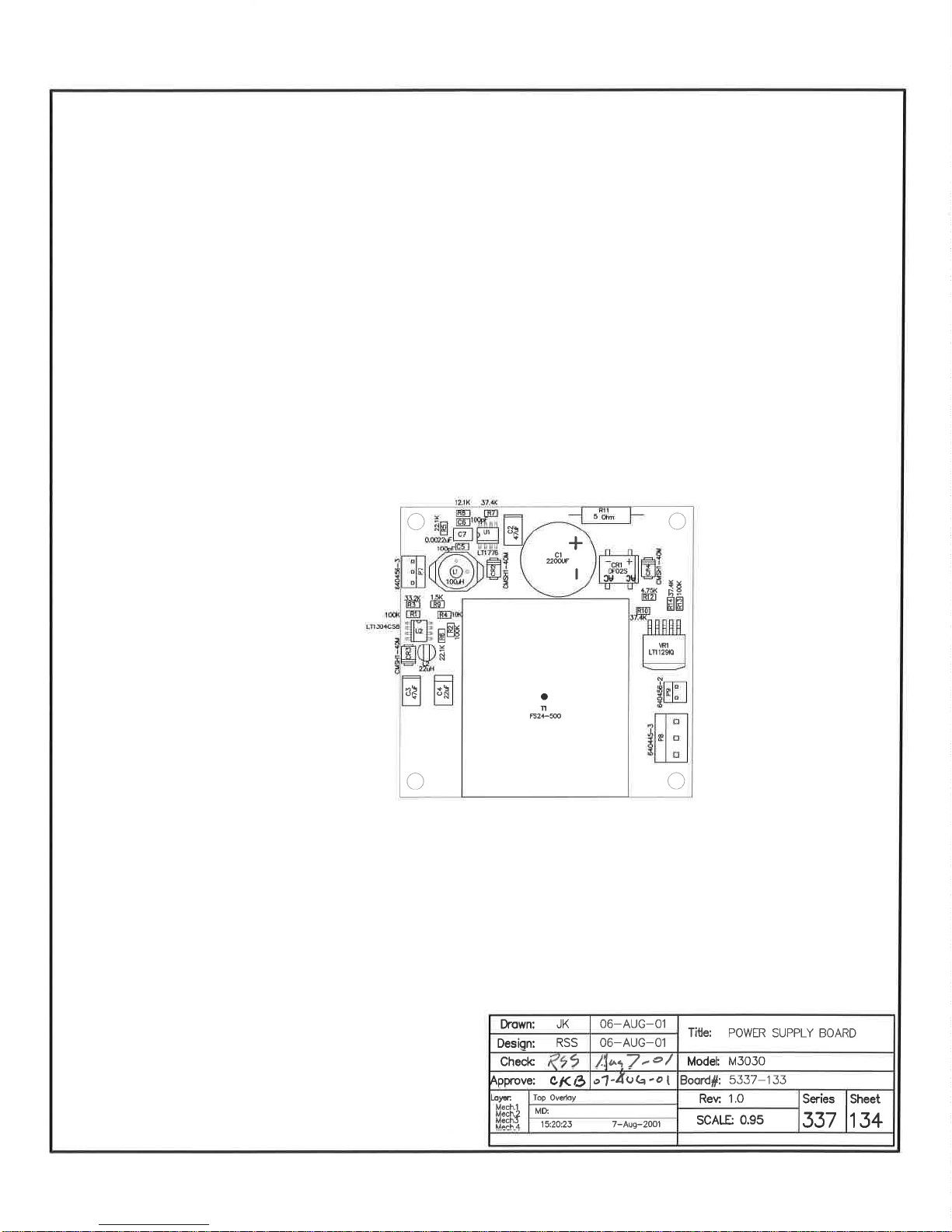


Model 3030 & 3030E Series Technical Manual Appendix A
Appendix
A
Model 3030-2 and 3030E-2
The Ludlum Model 3030-2 (LMI Part # 48-3992) and Model 3030E-2
(LMI Part # 48-3448-2) are dual-channel counters designed for
simultaneous alpha and beta sample measurement. Below are the
differences between the Model 3030/3030E and the 3030-2/3030E-2.
Counting Mode
The counts per minute (CPM), Becquerel (BQ), or counts per second
(CPS) modes may be enabled to allow the count to be converted
(automatically, in real time) to CPM, Becquerel, or CPS. The Becquerel
and CPS display modes will show the count with two decimal places.
Overload
The LCD display will toggle between the current reading and OL on
both the alpha and beta displays.
Sample Logging
The code for the logged sample changes to the following:
S - Scaler
C - Counts per minute
B - Becquerel
P - Counts per second
RS-232 Command Differences
The "D" command to set/read the counting mode changes to the
following:
D0 - Set count mode to scaler
D1 - Set count mode to counts per minute
D2 - Set count mode to Becquerel
D3 - Set count mode to counts per second
D4 - Read current count mode
The D4 command will return the following string:
"SCA" - Scaler
"CPM" - Counts per minute
"BQ " - Becquerel
"CPS" - Counts per second
PC Interface software (LMI Part# 1370-043)
Version 1.4.9 or higher is required and may be downloaded from the
LMI website http://www.ludlums.com.
Ludlum Measurements, Inc. Page A-1 November 2017
 Loading...