


LUDLUM MODEL 2929
DUAL-CHANNEL SCALER
January 2016
Serial Number 248597 and Succeeding
Serial Numbers

LUDLUM MODEL 2929
DUAL-CHANNEL SCALER
January 2016
Serial Number 248597 and Succeeding
Serial Numbers
Shown with a Model 43-10-1

STATEMENT OF WARRANTY
Ludlum Measurements, Inc. warrants the products covered in this manual to be free of
defects due to workmanship, material, and design for a period of twelve months from the
date of delivery. The calibration of a product is warranted to be within its specified
accuracy limits at the time of shipment. In the event of instrument failure, notify Ludlum
Measurements to determine if repair, recalibration, or replacement is required.
This warranty excludes the replacement of photomultiplier tubes, G-M and proportional
tubes, and scintillation crystals which are broken due to excessive physical abuse or used
for purposes other than intended.
There are no warranties, express or implied, including without limitation any implied
warranty of merchantability or fitness, which extend beyond the description of the face
there of. If the product does not perform as warranted herein, purchaser’s sole remedy
shall be repair or replacement, at the option of Ludlum Measurements. In no event will
Ludlum Measurements be liable for damages, lost revenue, lost wages, or any other
incidental or consequential damages, arising from the purchase, use, or inability to
product
.
use
RETURN OF GOODS TO MANUFACTURER
If equipment needs to be returned to Ludlum Measurements, Inc. for repair or calibration, please send to
the address below. All shipments should include documentation containing return shipping address,
customer name, telephone number, description of service requested, and all other necessary information.
Your cooperation will expedite the return of your equipment.
ATTN: REPAIR DEPARTMENT
501 OAK STREET
SWEETWATER, TX 79556
LUDLUM MEASUREMENTS, INC.
800-622-0828 325-235-5494
FAX 325-235-4672


Model 2929 Scaler Technical Manual
Table of Contents
Introduction 1
Specifications 2
Controls and Functions 3
Front Panel 3-1
Rear Panel 3-2
Safety Considerations 4
Environmental Conditions for Normal Use 4-1
Cleaning Instructions and Precautions 4-1
Warning Markings and Symbols 4-1
Recycling 5
Operating Procedures 6
Calibration Procedures 6-1
High Voltage Adjustment Procedures 6-2
Data Output 7
Function Identification 7-1
Function Source 7-1
Output Signals 7-1
Removing Data from the Model 2929 7-2
Optional Equipment 8
Model 264 Printer 8-1
Model 464 RS-232 Interface 8-1
Model 464-2 Two-Channel Counter 8-2
Parts List 9
Model 2929 Dual-Channel Scaler 9-1
Power Supply Board 9-1
Amplifier/Discriminator Board 9-2
Ludlum Measurements, Inc. January 2016

Model 2929 Scaler Technical Manual
Scaler Board 9-4
Clock/Logic Board 9-5
Dual Audio Board 9-6
6-Digit Readout Board 9-6
Mother Board 9-6
Preamp Board 9-7
Wiring Diagram 9-8
Drawings and Diagrams 10
Ludlum Measurements, Inc. January 2016

Model 2929 Scaler Technical Manual Section 1
Section
1
Introduction
he Model 2929 is a dual-channel scaler designed for use with
“Phoswich” and/or proportional detectors. A pulse height
T
The Model 2929 is powered by a 95 to 250 Vac wall transformer with an
output of 24 Vdc. It has a built-in detector high voltage power supply
with front panel readout, as well as adjustable count time periods
ranging from 0.1 to 990 minutes. It also has a click-per-event audio for
each of the two channels. The unit will operate two printing calculators
(Ludlum Model 264) by way of data connectors located on the rear
chassis. The amplifier circuitry consists of a three-stage amplifier fed
directly to the discriminator circuit. All discriminator controls are
located internally and are easily accessible internally on the right-hand
side of the chassis.
The Model 2929 is generally used in conjunction with a Model 43-10-1
Alpha/Beta Sample Counter.
analyzer is employed to provide information to the two
independent counters.
Ludlum Measurements, Inc. Page 1-1 January 2016

Model 2929 Scaler Technical Manual Section 2
Section
2
Specifications
0
Power: 95 to 250 Vac wall transformer with 24 Vdc output, 50-60 Hz
single phase (typically less than 100 mA)
Input Senstivity: Beta-gamma lower threshold is adjustable from 4 mV,
beta-gamma upper threshold is adjustable from 25 mV to 100 mV, and
alpha threshold is adjustable from 175 mV.
High Voltage (HV): fully adjustable from 200 to 2500 V ±100 V with
the capability of supporting 60-megohm scintillation loads to 1500 V
HV Meter: 6.4 cm (2.5 in.) panel analog meter readout
HV Meter Accuracy: ±10% of reference value
Audio: click-per-event type with volume control for each of the two
channels
Count Time: 0-99 minutes with multiplier of 0.1, 1.0 and 10; external
position for use with an external clock source
Timer Accuracy: The time base for the scaler is crystal-controlled and
has a timer accuracy of ±0.2% of the thumbswitch setting.
Scaler Readout: six-digit, light-emitting diode readout for each of the
two channels
Scaler Accuracy: ±2% of reference value
Size: 24.4 x 37.1 x 25.1 cm (9.6 x 14.6 x 9.9 in.) (H x W x L)
Weight: 5.5 kg (12.1 lb), including detector
Finish: beige powder coat with anodized front panel and silk-screened
nomenclature
Temperature Range: -20 to 50 °C (-4 to 122°F); may be certified for
operation for -40 to 65 °C (-40 to 150 °F)
Ludlum Measurements, Inc. Page 2-1 January 2016

Model 2929 Scaler Technical Manual Section 3
Section
3
Controls and Functions
Front Panel
High Voltage:
V to 2500 V. It provides a linear adjustment of the detector voltage supply.
Changing the detector voltage will cause the detector gain to change. A
linear change in voltage will cause an exponential change in detector gain.
The instrument will support 60-megohm scintillation loads to 1500 V.
HV Meter: a 6.4 cm (2.5 in.) panel meter displaying the high-voltage setting
continuously.
HV: a 10-turn dial used to adjust the detector high voltage.
ON/OFF: a toggle switch used to apply power to the instrument when in the
“ON” position.
Count Lamp: a red light indicating that the scaler is in the count cycle.
Count Switch: resets and starts the counting cycle. This switch will also
reset the two counters when depressed.
HOLD Switch: stops the count cycle without resetting the scaler display.
The counters will hold the value present at the time this button is depressed.
Minutes: a two-decade thumb-wheel switch used for presetting count time.
This switch is used in conjunction with the multiplier switch.
Multiplier: a rotary switch allowing selection of count time mulitpliers of
0.1, 1, 10 or an EXT position for timing using external clock sources.
Detector Input Connection: a series “C” coaxial connector used to supply
the detector with its bias voltage and also to return the signal from the
detector. (Other connectors are available upon request.)
a 10-turn potentiometer control for adjusting HV from 200
Ludlum Measurements, Inc. Page 3-1 January 2016

Model 2929 Scaler Technical Manual Section 3
Beta-Gamma Vol: a rotary control used to vary the audio output of the
beta-gamma channel from off to full volume.
Alpha Vol: a rotary control used to vary the audio output of the alpha
channel from off to full volume.
Alpha Count: a six-digit LED readout indicating counts received in the
alpha counting channel.
Beta-Gamma Count: a six-digit LED readout indicating counts received in
the beta channel.
Rear P anel
Amp Out: a BNC connector that provides access to the final amplifier stage. The
pulse is positive-going with a maximum amplitude of approximately 22 V.
Alpha Out: a 15-pin D type connector used as a data output for the alpha
counter. (Refer to Section 7 for a listing of pin numbers and their functions.)
Beta-Gamma Out: a 15-pin D type connector used as a data output for the beta-
gamma counter. (Refer to Section 7 for a listing of pin numbers and their
functions.)
Fuse: Use of a 1-Amp, fast-blowing fuse provides protection to the instrument
in case of internal electrical failure.
110 Vac: a connector used to apply line power to the instrument
Ludlum Measurements, Inc. Page 3-2 January 2016

Model 2929 Scaler Technical Manual Section 4
Section
4
Safety Considerations
Environmental Conditions for Normal Use
Indoor use only
No maximum altitude
Temperature range of -20 to 50°C (-4 to 122 °F); may be certified for
operation from -40 to 65 °C (-40 to 150 °F)
Maximum relative humidity of less than 95% (non-condensing)
Pollution Degree 2 (as defined by IEC 664).
Cleaning Instructions and Precautions
The Model 2929 may be cleaned externally with a damp cloth, using only
water as the wetting agent. Do not immerse the instrument in any liquid.
Observe the following precautions when cleaning:
1. Turn instrument OFF and disconnect the instrument power
cord.
2. Allow the instrument to sit for one minute before cleaning.
Warning Markings and Symbols
Caution!
The operator or responsible body is cautioned that the
protection provided by the equipment may be impaired if the
equipment is used in a manner not specified by Ludlum
Measurements, Inc.
Ludlum Measurements, Inc. Page 4-1 January 2016

Model 2929 Scaler Technical Manual
Caution!
Verify instrument voltage input rating before connecting to a
power converter. If the wrong power converter is used, the
instrument and/or power converter could be damaged.
The Model 2929 is marked with the following symbols:
DIRECT CURRENT (DC) (IEC 417, No. 5032): designates an input
receptacle that accommodates a power cord intended for connection to DC
voltages. This symbols appears on the back panel.
CAUTION, RISK OF ELECTRICAL SHOCK (per ISO 3864, No.
B.3.6): designates a terminal (connector) that allows connection to a voltage
exceeding 1 kV. Contact with the subject connector while the instrument is
on or shortly after turning off may result in electric shock. This symbol
appears on the front panel.
Section 4
CAUTION (per ISO 3864, No. B.3.1): designates hazardous live voltage
and risk of electric shock. During normal use, internal components are
hazardous live. This instrument must be isolated or disconnected from the
hazardous live voltage before accessing the internal components. This
symbol appears on the front panel. Note the following precautions:
Warning!
The operator is strongly cautioned to take the following
precautions to avoid contact with internal hazardous live parts
that are accessible using a tool:
1. Turn the instrument power OFF and disconnect the power
cord.
2. Allow the instrument to sit for one minute before accessing
internal components.
The “crossed-out wheelie bin” symbol notifies the consumer that the
product is not to be mixed with unsorted municipal waste when discarding;
each material must be separated. The symbol is placed near the DC
receptacle. See section 5, “Recycling” for further information.
Ludlum Measurements, Inc. Page 4-2 January 2016

Model 2929 Scaler Technical Manual
Section
Section 5
5
Recycling
udlum Measurements, Inc. supports the recycling of the electronics
products it produces for the purpose of protecting the environment
L
recycling systems. To this end, Ludlum Measurements, Inc. strives to supply
the consumer of its goods with information regarding reuse and recycling of
the many different types of materials used in its products. With many
different agencies – public and private – involved in this pursuit, it becomes
evident that a myriad of methods can be used in the process of recycling.
Therefore, Ludlum Measurements, Inc. does not suggest one particular
method over another, but simply desires to inform its consumers of the
range of recyclable materials present in its products, so that the user will
have flexibility in following all local and federal laws.
The following types of recyclable materials are present in Ludlum
Measurements, Inc. electronics products, and should be recycled separately.
The list is not all-inclusive, nor does it suggest that all materials are present in
each piece of equipment:
and to comply with all regional, national, and international agencies
that promote economically and environmentally sustainable
Batteries Glass Aluminum and Stainless Steel
Circuit Boards Plastics Liquid Crystal Display (LCD)
Ludlum Measurements, Inc. products that have been placed on the market
after August 13, 2005 have been labeled with a symbol recognized
internationally as the “crossed-out wheelie bin.” This notifies the consumer
that the product is not to be mixed with unsorted municipal waste when
discarding; each material must be separated. On the Model 2929, the symbol
will be placed on the rear panel.
The symbol appears as such:
Ludlum Measurements, Inc. Page 5-1 January 2016

Model 2929 Scaler Technical Manual Section 6
Section
6
Operating Procedures
Once the Model 2929 is calibrated for use with a specific detector, the highvoltage operating point must be determined. See HV adjustment procedures
below for details on selecting the proper operating voltage.
Count time: Selection should be based on the count rates being
observed and the desired statistical accuracy.
Volume Controls: Adjust to desired levels. Note that audio is operating
whether a count cycle is in process or not.
Detector: Connect the detector to the instrument using the cable
supplied with the instrument. Note that a cable length change can cause
a shift in calibration.
Printer: When operating two Model 264 printers and a recycle is
required, be sure that only one printer has its recycle switch “ON.”
Calibration Procedures
The following procedures apply to the Model 2929 when used in
conjunction with the Model 43-10-1 scintillator
NOTE: The following settings are normally:
Ludlum Measurements, Inc. Page 6-1 January 2016
Beta Threshold (B-G THS) = 4 mV
Beta Window (B-G WIN) = 50 mV
Alpha Threshold (ALPHA THS) = 175 mV
Amp/Disc Board
Apply a negative pulse of 10 mV amplitude to the DETECTOR
input of the Model 2929. A count rate greater than 25,000 cpm
should be used.

Model 2929 Scaler Technical Manual Section 6
Adjust the GAIN control located internally and to the right-hand
side of the instrument for a positive pulse amplitude of 200 mV (at
the AMP OUT connector).
This completes the amplifier gain calibration. The optimum amplifier
gain should be approximately 20.
Apply a negative pulse of 200 mV amplitude.
Attach an oscilloscope probe to pin 7 of U5 ad adjust B-G THS
WIDTH (R6) for a five-microsecond wide negative 5 V pulse.
Move the oscilloscope to pin 9 of U6 and apply a negative pulse of
4 mV amplitude.
Adjust B-G THS (R3) until negative 5-volt pulses appear.
Apply a negative pulse of 50 mV amplitude and adjust B-G WIN
(R2) until negative 5-volt pulses just disapper.
Apply a negative pulse of 175 mV amplitude and adjust ALPHA
THS (R4) until a 5-volt positive pulse appears at pin 6 of U6.
High Voltage Power Supply
With a high-voltage meter of at least 1000 megohm input
impedance, adjust the front-panel HV control for 1000 Vdc at the
detector connector.
Adjust R6 for a front-panel meter reading of 1 kV.
NOTE: If adjustment is necessary, a 10-pin extender board will be required.
With no detector attached, turn the HV dial to maximum (fully
clockwise) and adjust R13 for 1500 V. (Higher limits may be
necessary, depending upon the type of detector being used.
High V oltage Adjustment Procedures
High Voltage: Selection of an operating voltage is determined by the plateau
method. With this method, a graph of high-voltage settings versus counts
received from each channel is generated (source counts and background
counts). LMI uses
239
Pu as the alpha source; and 99Tc or 14C as beta sources.
Ludlum Measurements, Inc. Page 6-2 January 2016

Model 2929 Scaler Technical Manual Section 6
The following procedures describes the determination of the operating
voltage for a Model 43-10-1 detector, which is commonly used with the
Model 2929 dual channel scaler. Note that certain criteria must be met for
the background counts, source efficiencies, and crosstalk.
1. Connect the Model 43-10-1 to the counting instrument with proper
cable.
2. Place a calibrated
99
Tc source in the sample holder. Close and lock
the sample drawer.
3. Adjust the counting instrument HV until it receives at least 27% 4π
efficiency
4. Decrease HV by 25 volts.
5. Record the HV.
6. Record the
99
Tc source count and beta crosstalk in the alpha
channel.
7. Remove the
99
Tc source and record the background count in the
alpha and beta channels.
8. Place a calibrated
239
Pu source in the sample holder. Close and lock
the sample drawer.
9. Record the
239
Pu source count and the alpha crosstalk in the beta
channel.
10. Increase the HV by 25 volts.
Ludlum Measurements, Inc. Page 6-3 January 2016
11. Repeat Steps 5-10 until one or more of the following conditions
happen:
a. Beta background exceeds 80 cpm
b. Alpha background d exceeds 3 cpm
exc14eeds
c. Alpha crosstalk in the beta channel
10%
d. Beta crosstalk in the alpha channel exceeds 1%.
12. The operating voltage should be selected at a point where:
99
a.
Tc efficiency greater than or equal to 27%.
239
b.
Pu efficiency greater than or equal to 37%

Model 2929 Scaler Technical Manual Section 6
c. Alpha crosstalk in beta channel less than or equal to 10%
d. Beta crosstalk in alpha channel is less than or equal to 1%
e. Beta background is less than or equal to 80 cpm
f. Alpha background is less than or equal to 3 cpm.
Ludlum Measurements, Inc. Page 6-4 January 2016

Model 2929 Scaler Technical Manual Section 7
Section
7
Data Output
Function Identification
PIN FUNCTION
1 Count Complete
2 Printer Ready
3 Load Printer
4 Printer Clock
5 Ground
6 Count
7 Hold
8 +5 Vdc
9 Alpha Pulse Out
10 Beta/Gamma Pulse Out
11 Blanking
12 Bit 1
13 Bit 2
14 Bit 3
15 Bit 4
Function Source
All functions are from Model 2929 to accessory except:
PIN 2 Printer Ready
PIN 6 Count
PIN 7 Hold
Output Signals
Output signals are CMOS with LO = GROUND and HI = VOLTAGE
on Pin 8.
Pin 2 Printer Ready: Signal should be of the same voltage swing as the
signals from the Model 2929.
Ludlum Measurements, Inc. Page 7-1 January 2016

Model 2929 Scaler Technical Manual Section 7
6 Count: Signal should be pulled low to start counting.
Pin 7 Hold: Signal should be pulled low to stop counting.
Remo ving Data from the Model 2929
When the Model 2929 has timed out and counting stops, a HI pulse appears
on pin 1 (count complete). This pulse is approximately 2 milliseconds wide
and is used to signal the accessory unit that data is ready to be transmitted.
When the accessory unit is ready to accept the data, Pin 2 (printer ready) is
pulsed HI for a minimum of 2 milliseconds. When this Pin goes LO, data is
unloaded from the Model 2929 as follows:
The most significant digit appears first. This is valid at the negative eduge of
the first clock pulse and position continues until all digits have been read out.
At this time, Pin 3 (load printer) goes LO, signaling completion of data
transfer.
NOTE: Count Complete (Pin 1) and Printer Ready (Pin 2) are tied together.
The data is presented as BCD data on Pins 12 (BIT 1), 13 (BIT 2), 14 (BIT
3), and (BIT 4).
Figure 1
Ludlum Measurements, Inc. Page 7-2 January 2016

Model 2929 Scaler Technical Manual Section 7
To start the Model 2929 again, Pin 6 (count)
may be brought LO for a minimum of 100
milliseconds. The suggested circuit for this is
shown in Figure 2.
Pins 9 and 10 are +5 V pulses and are present
even if the Model 2929 is not in a count cycle.
Figure 2
Ludlum Measurements, Inc. Page 7-3 January 2016

Model 2929 Scaler Technical Manual Section 8
Section
8
Optional Equipment
Model 264 Printer
The LMI Model 264 accessory printer is offered as an option for the
Model 2929 Scaler.
A recycle switch on the Model 264 is provided for continuous cycling, if
desired. \When the counting time has reached the preset selection, the
count is printed, and the scaler and timer are reset to 0 to begin again.
The preset time is variable from 6 seconds up to 990 minutes.
The calculator may be used for any normal calculation function as long
as the keys are not activated at the same time the scaler is feeding its
information to the printer.
NOTE: When operating two Model 264 printers and a recycle is required,
be sure that only one printer has its recycle switch ON.
Model 464 RS-232 Interface
The LMI Model 464 RS-232 interface connects to the Model 2929,
allowing communication between the scaler and a device with an RS232c I/O (Input/Output), such as a personal computer (PC).
A command input through the RS-232 port to the interface is interpreted
and action is taken accordingly. The scaler can be started, stopped and have
data extracted by way of commands sent to the interface. The timed count
may be controlled by the scaler front panel, interface internal timer or by a
timer in the controlling device. The interface internal timer is programmable
to 4.5 days.
Other commands allow the user to read the interface timer, read the
current count, start a timed count using the interface internal timer, and
ask the interface if the timer has timed out.
Ludlum Measurements, Inc. Page 8-1 January 2016

Model 2929 Scaler Technical Manual Section 8
The interface is powered by the scaler and is reset when the scaler is
turned off.
Model 464-2 Two-Channel Counter
The Model 2929 with modified data output connector may be connected
to a Model 464-2 two-channel counter with a single cable for display on
a PC by way of a serial port.
Every 0.5 seconds, the counts are collected from the counter boards and
sent to the RS-232 port. The supplied software allows the user to
specify count time, alarms, and to log counts to disk.
NOTE: The Model 464-2 accumulates counts independently from the
Model 2929 and its internal timer. Pulses are sent to the Model 464-2
counters, regardless of the status of the Model 2929 control board. This
allows the user to take timed counts at the Model 2929 without affecting
the serial port operation.
Ludlum Measurements, Inc. Page 8-2 January 2016

Model 2929 Scaler Technical Manual Section 9
Section
9
Model 2929 DualChannel Scaler
Power Supply Board,
Drawing 337 x 27
CAPACITORS
TRANSISTORS
INTEGRATED
CIRCUITS
Parts List
Reference Description Part Number
UNIT Completely Assembled
Model 2929 48-1426
BOARD Assembled Power Supply
5337-031
C1 100pF, 3kV 04-5532
C2 2.2µF, 20V, DT 04-5508
C3 100µF, 10V, DT 04-5576
C4 0.1µF, 35V, DT 04-5574
C5 1µF, 35V, DT 04-5575
C6-C7 0.0056µF, 3kV, C 04-5522
C8-C9 0.01µF, 2kV, C 04-5525
C10 0.0056µF, 3kV, C 04-5522
C11 0.1µF, 100V, C 04-5521
C12 0.0056µF, 3kV, C 04-5522
C13 0.1µF, 100V, C 04-5521
Q1 MPSW51 05-5765
Q2 2N3904 05-5755
U1 LM358 06-6024
U2 LM385z-1.2 05-5808
Ludlum Measurements, Inc. Page 9-1 January 2016

Model 2929 Scaler Technical Manual Section 9
Reference Description Part Number
DIODE
RESISTORS
TRANSFORMERS
Amplifer/
Discriminator,
Drawing 337 x 19
CAPACITORS
CR1 1N4148 07-6272
CR2-CR5 GI250-2 07-6266
THERM-RL 1006 07-6322
THERM-RL 1006 07-6322
R1 220K, 1/4W, 5% 10-7066
R2-R3 1G, FHV-1, 2% 12-7686
R4 1M, 1/4W, 5% 10-7028
R5 301 OHM, 1/8W, 1% 12-7677
R6 2K TRIMMER 09-6798
R7 820K, 1/4W, 5% 10-7063
R8-R9 10K, 1/4W, 5% 10-7016
R10 1.5K, 1/4W, 5% 10-7065
R11 200 OHM, 1/4W, 5% 10-7006
R12 10M, 1/4W, 5% 10-7031
R13 500K TRIMMER 09-6792
R14 1M, 1/4W, 5% 10-7028
T1 L8050 X 50 40-0902
BOARD Assembled Discriminator 5337-026
C1 10µF, 20V, DT 04-5592
C2-C3 1µF, 35V, DT 04-5575
C5 0.1µF, 100V, C 04-5521
C10 47pF, 100V, C 04-5533
C11 0.1µF, 100V, C 04-5521
C12 1µF, 35V, DT 04-5575
C13 0.01µF, 100V 04-5523
C16 22µF, 35V, DT 04-5594
C18-C19 100pf, 100V, C 04-5527
C20-C21 0.01µF, 100V 04-5523
C22-C23 100pf, 100V, C 04-5527
C24 0.01µF, 100V 04-5523
C25 100pf, 100V, C 04-5527
C26 22µF, 35V, DT 04-5594
Ludlum Measurements, Inc. Page 9-2 January 2016

Model 2929 Scaler Technical Manual Section 9
V
Reference Description Part Number
TRANSISTORS
INTEGRATED
CIRCUITS
DIODE
OLTAGE REGULATORS
Q1 2N3904 05-5755
U1-U2 CA3096 06-6023
U3-U4 CA3290 06-6140
U5-U7 CD4098 06-6066
CR1 1N4148 07-6272
VR1 LM78L05 05-5815
R1-R4 10K TRIMMER 09-6794
R5 200K TRIMMER 09-6791
R6 50K TRIMMER 09-6790
R9 12K, 1/4W, 5% 10-7048
R10 10K, 1/4W, 5% 10-7016
R11 4.7K, 1/4W, 5% 10-7014
R12 22K, 1/4W, 5% 10-7070
R13-R14 10K, 1/4W, 5% 10-7016
R15 820K, 1/4W, 5% 10-7063
R16 330 OHMS, 1/4W, 5% 10-7053
R17 1K, 1/4W, 5% 10-7009
R18 10K, 1/4W, 5% 10-7016
R19 5.6K, 1/2W 11-7275
R20 1K, 1/4W, 5% 10-7009
R21 56K, 1/4W, 5% 10-7021
R23 5.6K, 1/4W, 5% 10-7042
R24 100K, 1/4W, 5% 10-7023
R26 10K, 1/4W, 5% 10-7016
R28 18K, 1/4W, 5% 10-7018
R29 2.7K, 1/4W, 5% 10-7055
R31 150K, 1/4W, 5% 10-7024
R33 820 Ohm, 1/4W, 5% 10-7060
R35 10K, 1/4W, 5% 10-7016
R37 1M, 1/4W, 5% 10-7028
R38-R39 5.6K, 1/4W, 5% 10-7042
R40 10K, 1/4W, 5% 10-7016
R41 56K, 1/4W, 5% 10-7021
R42 5.6K, 1/4W, 5% 10-7042
R43 100K, 1/4W, 5% 10-7023
R45 10K, 1/4W, 5% 10-7016
R47 24K, 1/4W, 5% 10-7059
R49 2.2K, 1/4W, 5% 10-7012
Ludlum Measurements, Inc. Page 9-3 January 2016

Model 2929 Scaler Technical Manual Section 9
R59 330 OHMS, 1/4W, 5% 10-7053
R66 1K, 1/4W, 5% 10-7009
R72 22K, 1/4W, 1% 10-7070
R74-R75 56K, 1/4W, 5% 10-7021
R76 10K, 1/4W, 5% 10-7016
R78 330 OHMS, 1/4W, 5% 10-7053
Scaler Board,
Drawing 167 x 170
CAPACITORS
INTEGRATED
CIRCUITS
RESISTORS
RESISTOR
NETWORK
BOARD Completely Assembled Scaler 5167-235
C1 100µF, 10V, DT 04-5576
C2 0.001µF, 100V, C 04-5519
C3 0.01µF, 10V 04-5523
C4 0.001µF, 100V, C 04-5519
U1 CD4001BE 06-6064
U2 CD4093BE 06-6030
U3 LS7031 06-6114
U4 CD4001BE 06-6064
U5 CD4098BE 06-6066
U6 CD4511BE 06-6065
U7 ULN2003A 06-6073
U8 CA3082 06-6004
R7 560K, 1/4W, 5% 10-7027
R9-R10 560K, 1/4W, 5% 10-7027
R18 4.7K, 1/4W, 5% 10-7014
R19 100K, 1/4W, 5% 10-7023
R20 4.7K, 1/4W, 5% 10-7014
RN1 33 OHM 14P DIP 12-7771
RN2 10K 14P DIP 12-7772
Ludlum Measurements, Inc. Page 9-4 January 2016

Model 2929 Scaler Technical Manual Section 9
Reference Description Part Number
Clock/Logic Board,
Drawing 167 x 363
CRYSTAL
CAPACITORS
TRANSISTORS
INTEGRATED
CIRCUITS
DIODES
RESISTORS
CONNECTORS
BOARD Completely Assembled
Clock/Logic 5167-362
Y1 Micro Xtal X0-43B-1.0 01-5356
C1 0.01µF, 100V 04-5523
Q1 2N3904 05-5755
U1 CD4093 06-6030
U2 CD4001 06-6064
U5-U7 CD4017 06-6001
U8 CD40102 06-6062
U138-U139 RDD104 06-6060
CR142 1N4001 07-6268
R1 22K, 1/4W, 5% 10-7070
R2 220K, 1/4W, 5% 10-7066
R3-R4 22K, 1/4W, 5% 10-7070
R8 560K, 1/4W, 5% 10-7027
R9 1K, 1/4W, 5% 10-7009
R10 560K, 1/4W, 5% 10-7027
R11-R18 56K, 1/4W, 5% 10-7021
JP141 531220-22P 13-8099
103186-1 HEADER 13-8471
Ludlum Measurements, Inc. Page 9-5 January 2016

Model 2929 Scaler Technical Manual Section 9
Dual Audio Board,
Drawing 337 x 58
CAPACITORS
TRANSISTORS
INTEGRATED
CIRCUITS
RESISTORS
TRANSFORMERS
6-Digit Readout
Board, Drawing
167 x 29
INTEGRATED
CIRCUITS
Mother Board,
Drawing 337 x 219
CAPACITORS
Reference Description Part Number
BOARD Assembled Dual Audio 5337-066
C2-C5 0.01µF 04-5523
C6 100µF, 10V, DT 04-5576
Q1-Q2 VN2222LL 05-5816
U1-U2 ICM7555IPA 06-6136
U3 CD4098BE 06-6066
R1 10K, 1/4W, 5% 10-7016
R2 2.2MEG 1/4W, 5% 10-7052
R3 33K, 1/4W, 5% 10-7019
R4-R5 1 OHM, 1% 12-7555
R7 56K, 1/4W, 5% 10-7021
R8-R9 10K, 1/4W, 5% 10-7016
R11 10K, 1/4W, 5% 10-7016
R12 2.2MEG, 1/4W, 5% 10-7052
R13-R14 33 OHM, 1/4W, 5% 10-7001
T1-T2 M177-1 AUDIO 40-0948
BOARD 6-Digit Readout 5167-030-00
U1-U6 LED-HP5082-7653 07-6283
BOARD Assembled Mother Board 5337-219
C1 100µF, 35V 04-5595
C2-C3 10µF, 20V 04-5592
C4 100µF, 35V 04-5595
C5 0.1µF, 100V 04-5521
C6 100µF, 10V 04-5576
C7-C9 10µF, 20V 04-5592
Ludlum Measurements, Inc. Page 9-6 January 2016

Model 2929 Scaler Technical Manual Section 9
Reference Description Part Number
RESISTORS
DIODES
VOLTAGE
REGULATORS
CONNECTORS
INDUCTOR
FUSES
Preamp Board,
Drawing 337 x 22C
CAPACITORS
INTEGRATED
CIRCUITS
R1 560 OHM, 1/4W, 5% 10-7054
R3 10K, 1/4W, 1% 12-7540
R5 560 OHM, 1/4W, 5% 10-7054
CR1 1N5819 07-6306
CR2 1N4001 07-6268
VR1 LM2597-5.0 06-6723
VR2 LM78L12ACZ 05-5812
P1 CJ50-20A-30 13-8050
P2-P3 1-640456-4 MTA 100X14 13-8141
P4 CJ50-44A-30 13-8083
P5 CJ50-20A-30 13-8050
P6-P7 CJ50-30A-30 5167-021-00 13-8052
P9-P10 DB15RA/F-P 13-8576
P11 640456-5 MTA 100X5 13-8057
P12 CJ50-44A-30 5167-362 13-8083
P15 640456-8 MTA 100X8 13-8039
P17 640456-9 MTA 100X9 13-8094
P18 MTA100X11 13-8059
P19-P20 640456-4 MTA 100X4 13-8088
J1 RAPC712 13-8445
J2 BNC-RA-50 OHM 21-8976
L1 DO3308P-154 22-9301
F1 DO3308 THERMAL FUSE 21-9031
BOARD Assembled Preamp 5170-027
C1 100pF, 3kV, C 04-5532
C3 1µf, 35V, DT 04-5575
U1 CA3096E 06-6023
Ludlum Measurements, Inc. Page 9-7 January 2016

Model 2929 Scaler Technical Manual Section 9
RESISTORS
MISCELLANEOUS
Wiring Diagram,
Drawing 337 x 66
CAPACITORS
CONNECTORS
SWTICHES
DIODES
Reference Description Part Number
R3 22K, 1/4W, 5% 10-7070
R5 22K, 1/4W, 5% 10-7070
R6 10K, 1/4W, 5% 10-7016
R7 33K, 1/4W, 5% 10-7019
R10 330 OHMS, 1/4W, 5% 10-7053
R12 10K, 1/4W, 5% 10-7016
R13 1K, 1/4W, 5% 10-7009
2 EA. RECPT-CLOVERLEAF
011-6809 18-8771
C2 0.0015µf, 3KV, C 04-5518
C3 10,000µF, 50V 04-5577
C4 1600µF, 50V 04-5535
C5-C6 0.1µF, 35V, T 04-5501
J1 RECPT-EAC 309 13-7982
P1 EDGE-CJ50-20A-30 10 PIN 13-7852
P2-P3 EDGE-CJ50-30A-30 15 PIN 13-7853
P4 EDGE-CJ50-44A-30 22 PIN 13-7866
P5 EDGE-CJ50-20A-30 10 PIN 13-7852
P6-P7 EDGE-CJ50-30A-30 15 PIN 13-7853
P8 RECPT-UG931/U PANEL MHV 13-7757
P9-P10 “D” RECPT RD15F000V30
15 PIN 13-7789
P11 Hard-Wired
P12 EDGE-CJ50-44A-30 22 PIN 13-7866
P13 RECPT-UG568/U PANEL C 13-7752
P14 CONN-RECPT-UG1094/U
SCREW BNC 13-7753
S1 30-1-PB GRAYHILL 08-6517
S2 TOGGLE 7952-K6 08-6525
S3 30-1-PB GRAYHILL 08-6517
S4 GRAYHILL
55D36-01-2-AJN 08-6514
2 EA. 177602G-ECCO 08-6521
CR1 1N5242 07-6264
CR2-CR3 1N4001 07-6268
CR4 PILOT RED LAMP 21-9299
Ludlum Measurements, Inc. Page 9-8 January 2016

Model 2929 Scaler Pulser Technical Manual Section 9
V
Reference Description Part Number
RESISTORS
TRANSFORMER
REGULATORS
MISCELLANEOUS
OLTAGE
F1 FUSE - #312001 3-AGC-1 21-9277
FUSE HOLDER 341001 21-9269
DS1 UNIMORPH 21-9251
DS2 UNIMORPH 21-9251
DS3 LAMP-IDI 2110A1 21-9296
LAMP-IDI 2110A1 21-9296
M1 METER ASSEMBLY 4167-302
LAMP-CLIP
515-0051 21-9300
LAMP-PLUG
515-0074 21-9301
2 EA. BRIDGE RECT-250JB1L 07-6281
R1 10K, 10-TURN 09-6761
R2 1 MEG, 1/4W, 5% 10-7028
R3 10K TRIMMER 09-6753
R9 10K, 1/4W, 5% 10-7016
R11 10K TRIMMER 09-6753
R13 2.2K, 1/4W, 5% 10-7012
T1 M2929 X5 4275-023
VR1 LM323K 05-5773
VR2 LM340K-24 05-5774
Ludlum Measurements, Inc. Page 9-9 January 2016

Model 2929 Scaler Technical Manual Section 10
Section
10
Drawings
Power Supply Board, Drawing 337 x 27
Power Supply Board Component Layout, Drawing 377 x 35
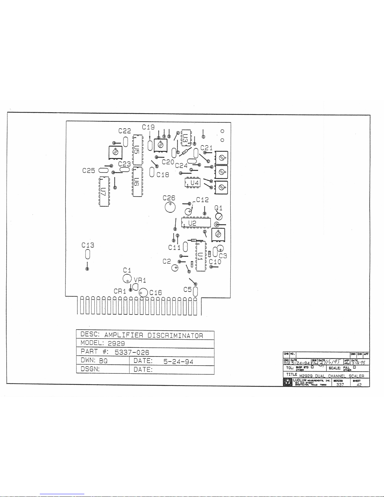
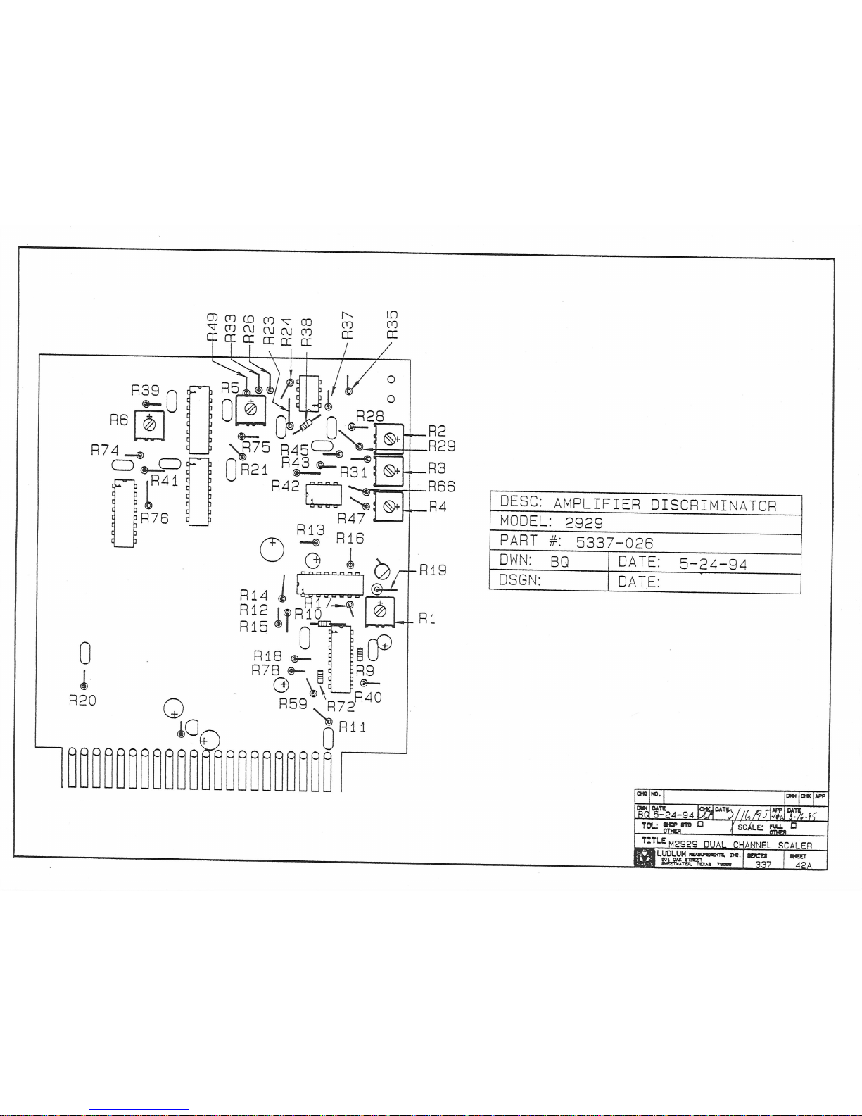
Amplifier/Discriminator Board, Drawing 337x 19
Amplifier/Discriminator Board Component Layout, 337 x 4-42A
Scaler/Ratemeter Board, Drawing 167 x 170
Scaler/Ratemeter Board Component Layout, Drawing 167 x 176
Clock/Logic Board, Drawing 167 x 363
Clock/Logic Component Layout, Drawing 167 x 364
Dual Audio Board, Drawing 337 x 58
Dual Audio Component Layout, Drawing 337 x 59
6-Digit Readout Board, Drawing 375 x 60 (2 sheets)
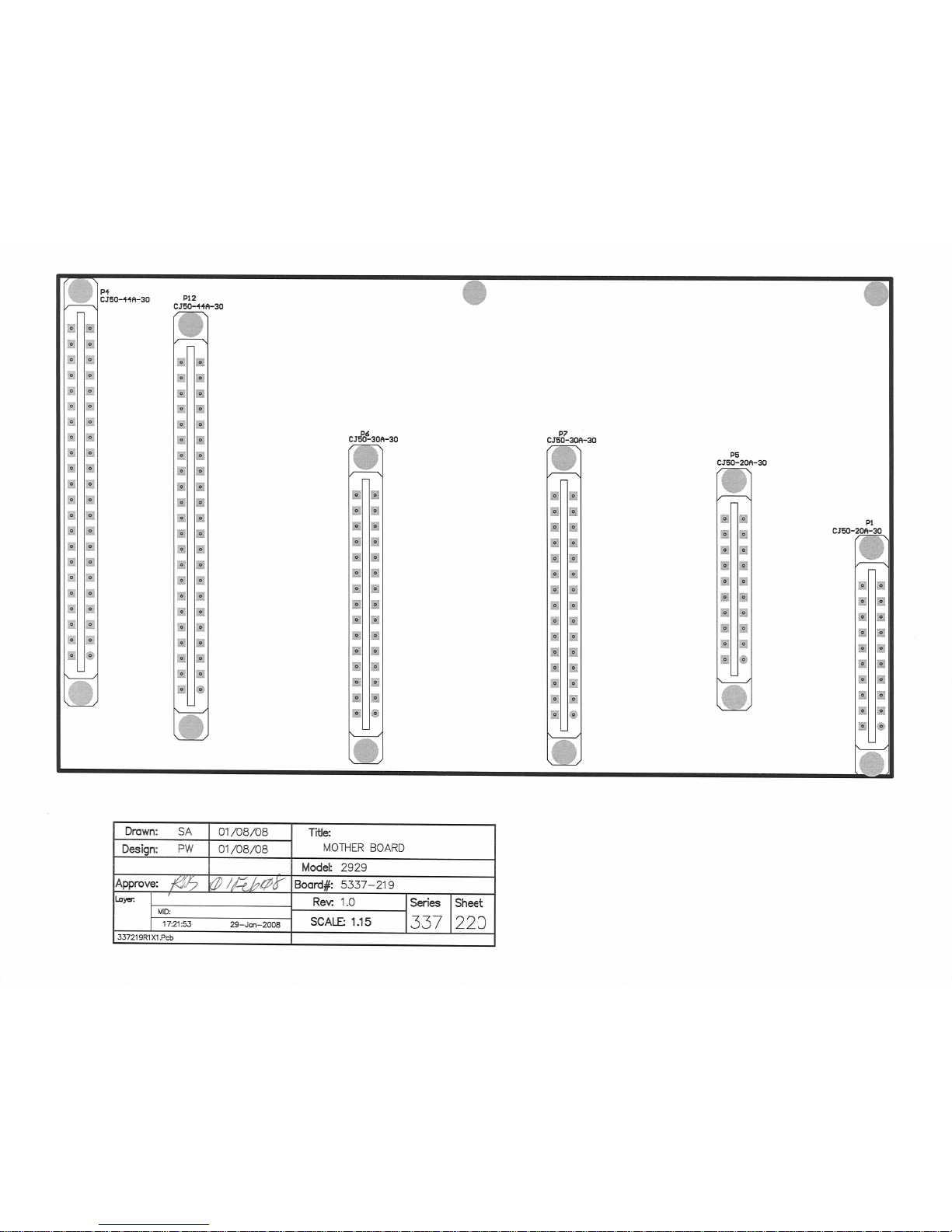
Mother Board, Drawing 337 x 219
Mother Board Component Layout, Drawing 337 x 220 (2 sheets)
Preamp Board, Drawing 337 x 22
Preamp Board Component Layout, Drawing 170 x 31
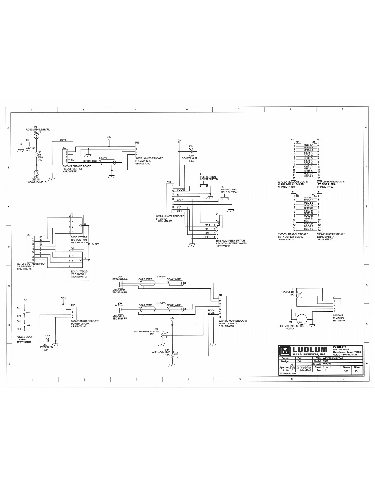
Wiring Diagram, Drawing 337 x 231
Ludlum Measurements, Inc. Page 10-1 January 2016


 Loading...