

Page 1

User�s Guide
Rev : 1.0
Date : July, 1999
Table of Contents���������� �����
Chapter 1Introduction������������������� ���������������������������������������������������� 2
1-1 Features and
Specifications����������� ��������������������������������������� 2
1-2 Package
Checklist�������� ��������������� ����������������������������������������������� 5
Chapter 2-Hardware Setup������������ ���������������������������������������������������� 6
2-1 System Board
Layout����������������� ��������������������������������������� 6
2-2 CPU Type
Configuration�������������� ����������������������������������������������� 7
2-3 Jumper
Settings������������������������ ��������������������������������������� 8
2-4 Header Location and
Description����� ��������������������������������������� ������� 10
2-5
Connectors����������������������������� ��������������������������������������� 14
2-6
Slots������������������������������������� ��������������������������������������� 15
Chapter 3-Award BIOS Setup Utility���������������������������������������� ���������� 17
3-1 CMOS Setup
Utility������������������� ��������������������������������������� 18
3-2 Standard CMOS
Setup���������������� ��������������������������������������� 19
3-3 BIOS Features
Setup������������������ ��������������������������������������� 20
3-4 Chipset Features
Setup���������������� ��������������������������������������� 23
3-5 Power Management
Setup������������ ��������������������������������������� 25
3-6 PnP/PCI Configuration
Setup��������� ��������������������������������������� 27
3-7 Load Setup
Defaults������������������� ��������������������������������������� 28
3-8 Integrated Peripherals
Setup���������� ��������������������������������������� 28
3-9 Supervisor/User
Password����������� ��������������������������������������� 30
3-10 HDD Auto
Detection����������������� ��������������������������������������� 31
3-11 Save & Exit
Setup�������������������� ��������������������������������������� 31
3-12 Exit Without
Saving������������������ ��������������������������������������� 31
Chapter 1-Introduction
1-1 Features and Specifications
Chipset
< VIA Apolo Chipset
< PCI Rev 2.1, 5V, 33MHz interface compliant
< Supports 66/68/75/83MHz, 3.3V AGP (Accelerated Graphics Port) slot
< Supports Ultra DMA33/66 Master Mode PCI-EIDE controller
CPU
< Supports Intela Celeron 370 CPU and other compatible CPUs using
< Supports CPU voltage auto-detect circuit
< Supports 66/100MHz Bus Clock
System Memory
Page 2

< Memory range from 8MB (minimum) to 256MB (maximum) SDRAM with
DRAM table free configurations
< Supports 2pcs 168-pin DIMM sockets (3.3V Unbuffered and 4 Clock type)
< Up to 2 double side DIMM module that support 16MB, 64MB, 128MB,
256MB SDRAM technology
< Supports SDRAM with PC-100
< 4MB VGA SDRAM memory on board (option)
< DRAM supports ECC or Parity function
L2 Cache
Intel Celeron Socket 370 CPU supports 128K write back cache with
Pipelined Burst SRAMs
Compatibility
< Microsoft PC98 compliant
< VESA Display Power Management Signaling (DPMS)
< VESA DDC2B for Plug and Play monitors
< PCI 2.2, AMR 1.0 and AC97 compliant
< Two USB ports
< One NS16C550A-compatible DB-9 serial port
< One NS16C550A-Compatible COM Port header with bracket
< One DB-15 VGA port
< One SPP/ECP/EPP DB-25 parallel port
< One mini-DIN-6 PS/2 mouse port
< One mini-DIN-6 PS/2 keyboard port
< One game/MIDI port
< Three audio jacks : line-out, line-in, mic-in
IrDA Interface
The system board is equipped with an IrDA connector for wireless
connectivity between your computer and peripheral devices. It support
peripheral devices that meet the IrDA or ASKIR standard.
USB Ports
The system board is equipped with two USB ports. USB allows data exchange between your computer and a wide range of simultaneously accessible external Plug and Play peripherals.
BIOS
< Award Plug and Play BIOS
< Flash EPROM for easy BIOS upgrades
< Supports Advanced Power Management (APM) function and ACPI
(Advanced Configuration and Power Management) function
Super I/O Function
< Integrated USB (Universal Serial Bus) controller with two USB ports
< Supports two IDE channels with 4 IDE devices (including ZIP/LS-120
devices)
< Provides PCI IDE Bus Master function and supports Ultra DMA33/Ultra
DMA66 function
< Supports One Floppy Port
< Supports two high speed 16550 FIFO UART ports
< Supports one parallel port with EPP/ECP/SPP capabilities
< Supports PS/2 Mouse connector
< Built-in RTC, CMOS, Keyboard connector on single I/O chip
< Peripherals boot function (with ATX power)
Other Function
< ATX size 220mm * 220mm
< 3pcs PCI Slots
< 2pcs ISA Slots
< Supports Wake On LAN (WOL) function
< Supports keyboard power on function
< 1pcs AGP Slot
< 2pcs DIMM Slots
System Health Monitor Function
Page 3

The system board is capable of monitoring the following �system health�
conditions.
< Monitors processor/system/other devices temperature and over heat
alarm
< Monitors 5VSB/VBAT/3.3V/5V/�12V/processor voltages and failure alarm
< Monitors processor/chassis/power supply fan speed, controls
processor/chassis fan speed and failure alarm
< Automatic fan on/off control
< Read back capability that display temperature, voltage and fan speed
If you want a warning message to pop-up or a warning alarm to sound when
an abnormal condition occurs, you must install the Hardware Doctor utility.
This utility is included in the CD that came with the system board. Refer to
the Hardware Doctor Utility section in chapter 4 for more information.
RTC Timer to Power-on the System
The RTC installed on the system board allows your system to automatically
power-on on the set date and time.
Power On Function
This function allows you to use the keyboard or mouse to power-on the
system. Refer to �Setting the Power On Function� in chapter 3 for more
information.
Note :
1. The power button will not function once a keyboard password has been set
in the �KB Power On Password� field of the Integrated Peripherals
submenu. You must type the correct password to power-on the system. If
you forget the password, power-off the system and remove the battery.
Wait for a few seconds and install it back before powering-on the system.
2. The 5VSB power source of your power supply must support � 720mA
(minimum). If you are using the Suspend to RAM function, the 5VSB power
source must support a minimum of � 1.2A.
AC Power Failure Recovery
When power returns after an AC power failure, you may choose to either
power-on the system manually, let the system power-on automatically or
return to the state where you left off before power failure occurs. Refer to
�Selecting the Power Lost Resume State� in chapter 3 for more
information.
Year 2000 Compliant
Supports hardware Y2K function. Supports hardware Random Number
Generator (RNG) to enable a new security and manageability infrastructure
for PC.
ACPI
The system board is designed to meet the ACPI (Advanced Configuration
and Power Interface) specification. ACPI has energy saving features that
enables PCs to implement Power Management and Plug-and-Play with
operating systems that support OS Direct Power Management. Currently,
only Windows 98 supports the ACPI function. ACPI when enabled in the
Power Management Setup will allow you to use the Suspend to RAM
function.
With the Suspend to RAM function enabled, you can power-off the system at
once by pressing the� power button or selecting �Standby� when you
shut down Windows 98 without having to go through the sometimes tiresome
process of closing file, applications and operating system. This is because
the system is capable of storing all programs and data files during the entire
operating session into RAM (Random Access Memory) when it powers-off.
The operating session will resume exactly where you left off the next time
you power-on the system. Refer to �Using the Suspend to RAM Function�
in chapter 3 for more information.
1-2 Package Checklist
The system board package contains the following items :
□The System Board
□User�s Guide
□ One IDE cable for ATA/33 IDE driver
□One IDE cable for ATA/66 IDE driver
□One 34-pin floppy disk drive cable
□One �Super VB� CD
□One card-edge bracket with a serial port
If any of these items are missing or damaged, please contact your dealer or
sales representative for assistance.
Chapter 2-Hardware Setup
Page 4
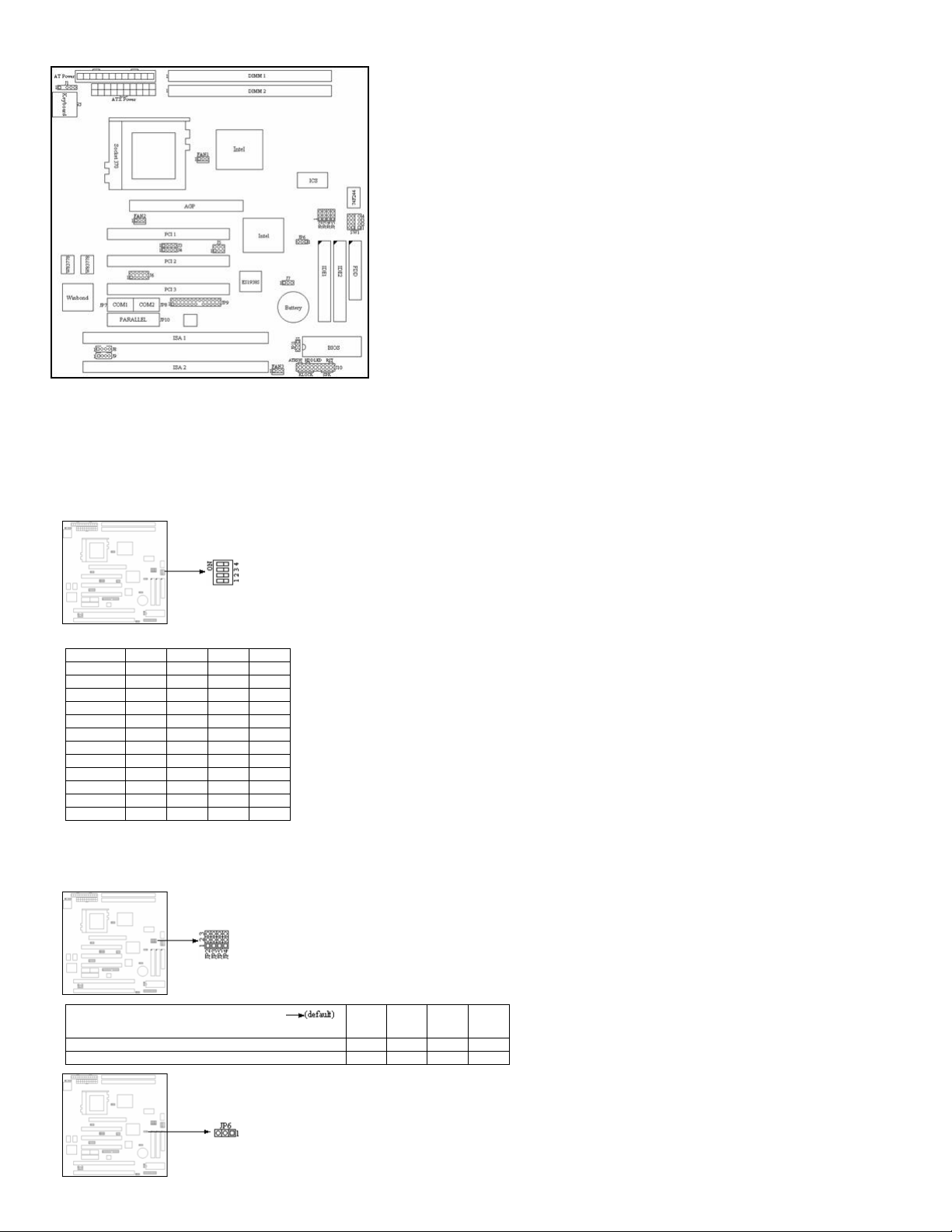
2-1 System Board Layout
2-2 CPU Type Configuration
This motherboard is jumperless for CPU settings, as a result that user can
select CPU settings in the Award BIOS program without toggling the jumpers
on the motherboard manually.
< CPU Host/PCI Clock
Supports 66/100MHz Bus Clock (from BIOS).
< CPU Ratio
2x, 2.5x, 3x, 3.5x, 4x, 4.5x, 5x, 5.5x, 6x,
6.5x, 7x, 7.5x
SW1 1 2 3 4
2.0x ON ON ON ON
2.5x OFF ON ON ON
3.0x ON OFF ON ON
3.5x OFF OFF ON ON
4.0x ON ON OFF ON
4.5x OFF ON OFF ON
5.0x ON OFF OFF ON
5.5x OFF OFF OFF ON
6.0x ON ON ON OFF
6.5x OFF ON ON OFF
7.0x ON OFF ON OFF
7.5x OFF OFF ON OFF
2-3 Jumper Settings
JP2~JP5 : Clock Frequency Setting
The jumper allows user to control CPU Host Clock.
CPUCLK
JP2 JP3 JP5 JP4
66MHz 2-3 2-3 1-2 1-2
100MHz 2-3 1-2 1-2 1-2
JP6 : Clear CMOS setting
Page 5
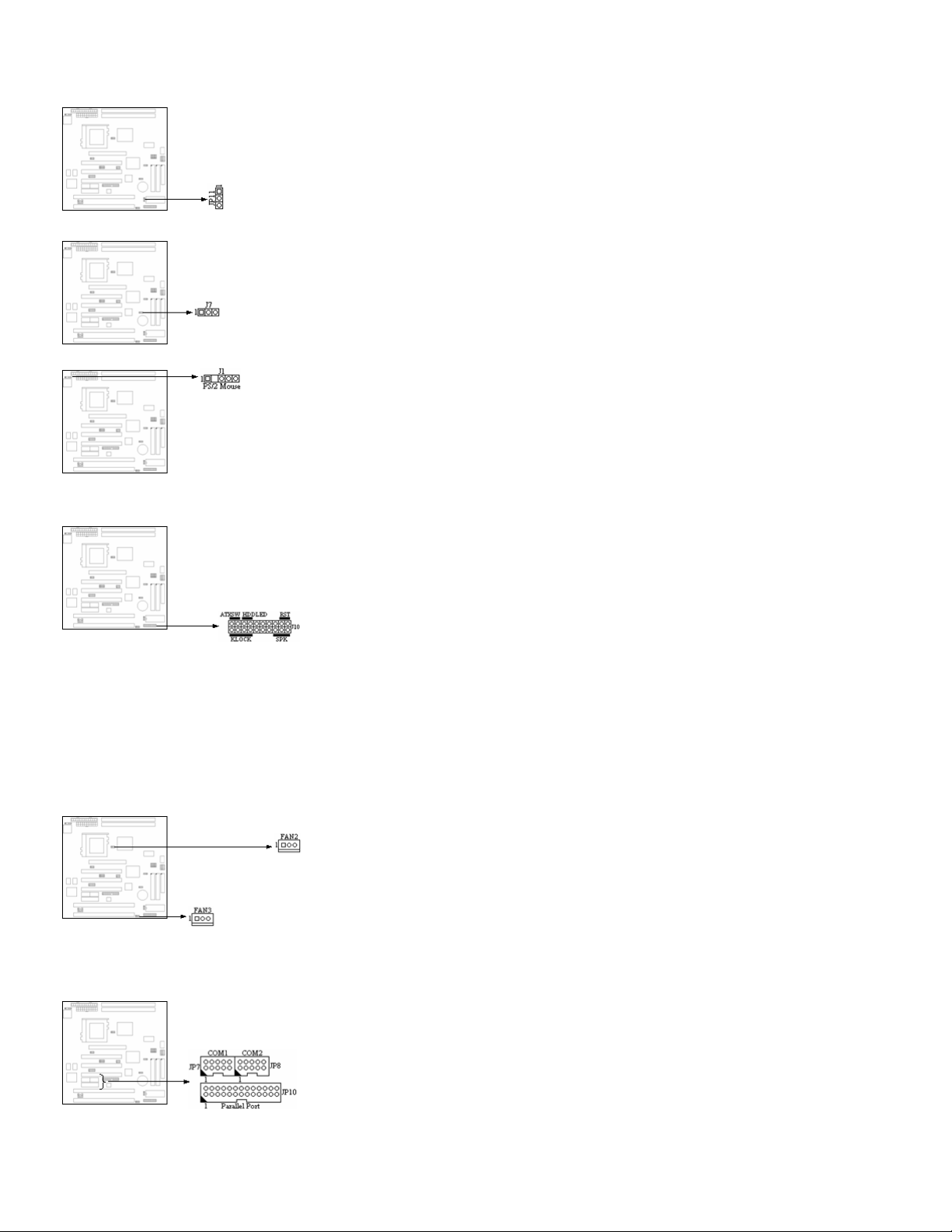
A battery must be used to retain the mainboard configuration in CMOS RAM. To retain the on board battery you must always short pin (1-2) of JP6. You can clear CMOS by shorting (2-3) pin, while the
system is off. Then, return to (1-2) pin position. Avoid clearing the CMOS while the system is on, it will damage the mainboard.
JP11 : Flash ROM Voltage Select
12V � short pin (2-3); 5V � short pin (1-2).
J7 : Wake Up on LAN connector
Provides a 3-pin LAN Wake Up header to support Wake Up on LAN function.
J1 : PS/2 Mouse
The mainboard provides a 5-pin connector and a PS/2 Mouse cable. You can plug a PS/2 Mouse to PS/2 Mouse cable.
2-4 Header Location and Description
J10 : Front Panel
The HDD LED, Speaker, Power On, KeyLock button are all located at the bottom right corner of the mainboard.
1. RESET � Reset switch are used to reboot the system rather than the
power On/Off.
2. Speaker � Speaker from the system case are connected to this pin.
3. HDD LED � HDD LED shows the active of hard disk drive.
4. ATXSW � Depending on the setting in the �soft-off by PWR-BTTN� field
in the Power Management Setup, this switch is a �dual function power
button� that will allow your system to enter the soft-off or suspend mode.
5. KeyLock � KeyLock is a Keylock connector that enabled and disabled the
keyboard and the Power-Led on the case.
FAN1 / FAN2 / FAN3 : AGP / CPU / System FAN
Provide three Fan connectors to supports CPU, AGP and system Fan. The FAN1 is AGP Fan. The Fan2 is CPU Fan. And the Fan3 is System Fan. These connectors also could be control and provides
speed monitoring function.
JP7 / JP8 / JP10 : COM1 / COM2 / Parallel Port
COM1, COM2 - The mainboard provides a 10-pin header to connect one card-edge bracket with a serial port 9-pin connectors to support 16550 FIFO UART port. The port is 16550A fully compatible high
speed.
Parallel Port � The mainboard provides a Header and attach a cable for LPT. A parallel port is a standard printer port that also supports Enhanced Parallel Port (EPP) and Extended
capabilities Parallel Port (ECP).
Page 6
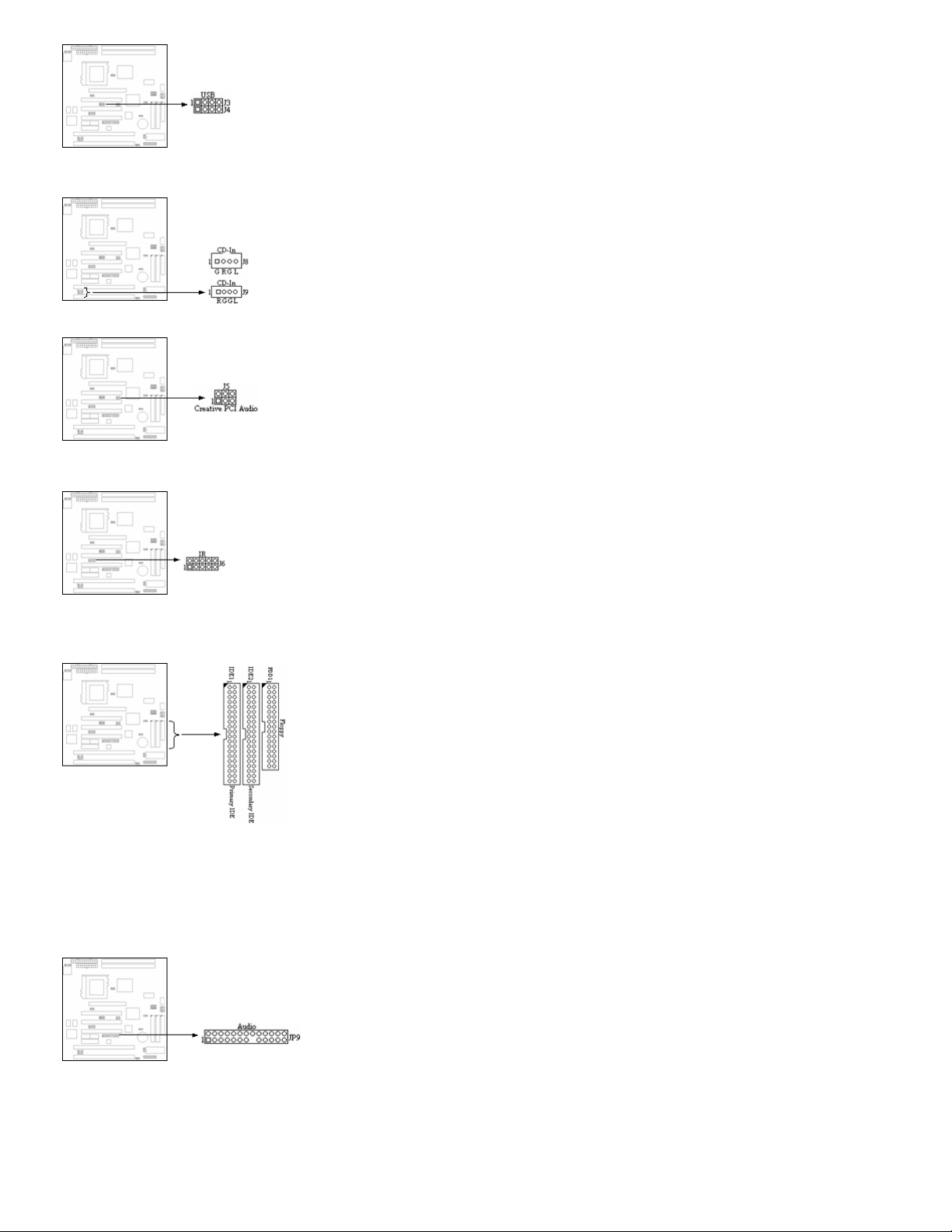
J3, J4 : USB
Attach the USB cable to provide connection to USB devices.
J8, J9 : CD-In
Provide two difference dimension to support CD-In function. The J9 pitch is
2.0mm, J8 is 2.54mm.
J5 : Creative PCI Audio
Provides a 2*3-pin header to support Creative PCI Audio function.
J6 : IR
The system board provides a 2*5-pin header as an option module for
wireless transmitting and receiving.
IDE1 / IDE2 / FDD1 : Primary / Secondary / Floppy
The mainboard has two Ehanced PCI IDE controller that provides two
connectors, the IDE1 is Primary IDE Connector. IDE2 is Secondary IDE
Connector.
The mainboard also provide a standard floppy disk connector, that supports
360K, 720K, 1.2M, 1.44M and 2.88M floppy disk types. You can attach a
floppy disk cable directly to this connector.
JP9 : Audio
Attach a Audio cable connection with JP9 to support Line-In, Line-Out, Mic and Game port device.
2-5 Connectors
PW1 / PW2 : AT / ATX Power connector
Page 7
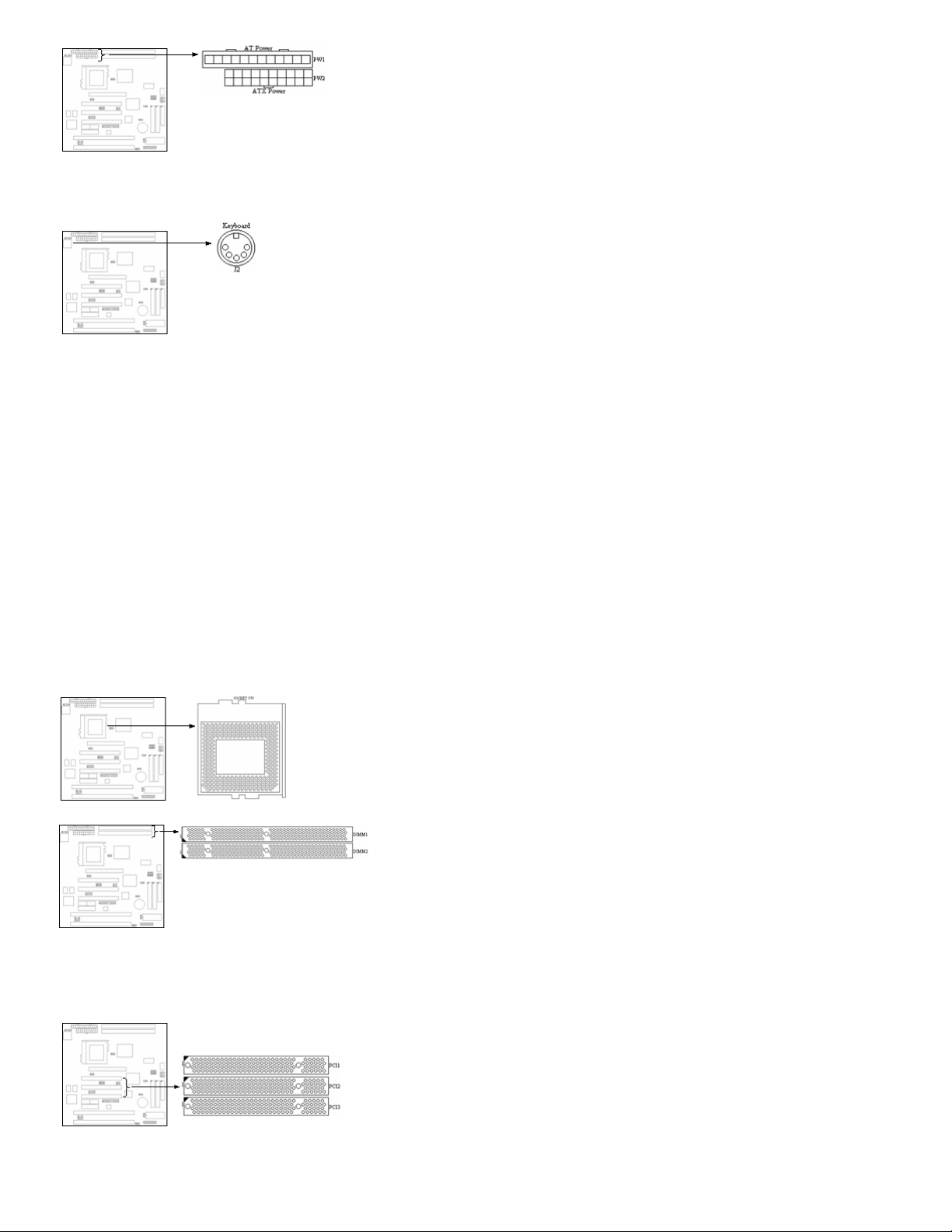
PW1 � A standard 12-pin AT connector. Be sure to attach the connectors with the two black wires at center.
PW2 � This type of connector already support the remote ON/OFF and soft-off.
J2 : Keyboard connector
A 5-pin female DIN keyboard connector is located at the upper right corner of the mainboard. Plug the keyboard jack directly into this connector.
Socket 370 connector
This mainboard support one Socket 370 connector.
2-6 Slots
DIMM1, DIMM2
The mainboard provides two 168-pin DIMM socket. It support six memory
bank for a maximum of 512MB memory. Each bank supports up to 256MB
memory. You can use DIMM from 4M, 8M, 16M, 32M, 64M, 128M and 256M.
PCI1, PCI2, PCI3
There are three PCI slot can used as master.
ISA1, ISA2 Slot
Page 8
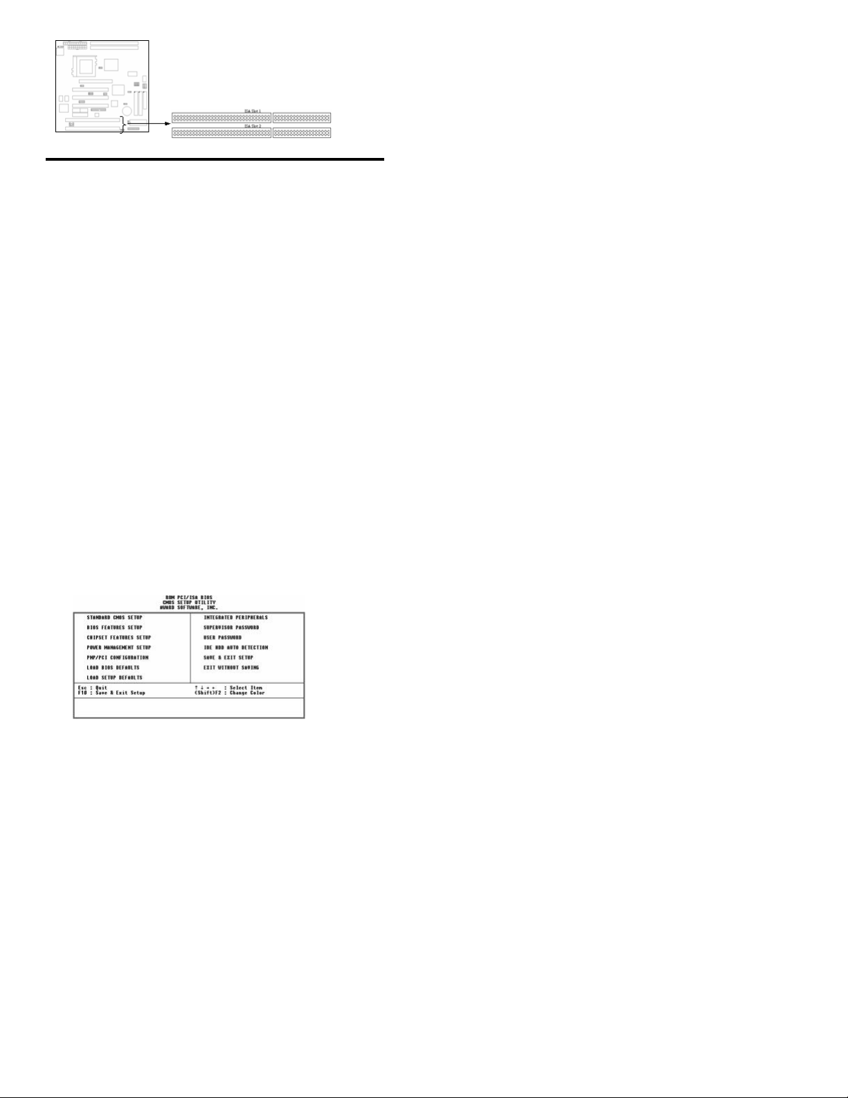
There are provides two ISA Slots.
Chapter 3-Award BIOS Setup Utility
The ROM chips of your mainboard are configured with a customized Basic
Input/Output System (BIOS) from Award Software Inc. The BIOS is a set of
permanently recorded program routines that give the system its fundamental
operational characteristics. It also tests the computer and determines how
the computer reacts to specific instructions that are part of programs.
The BIOS is made up of codes and programs that provide the device level
control for the major I/O devices in the system. It contains a set of routines
(called POST, for Power-On Self Test) that check out the system when you
turn it on. The BIOS also includes CMOS Setup programs, so no disk-based
setup program is required. CMOS RAM stores information for :
< the date and time
< the memory capacity of the mainboard
< the type of display adapter installed
< the number and type of disk drives installed.
The CMOS memory is maintained by a battery installed on the mainboard.
By using the battery, all memory in CMOS can be retained when the system
power switch is turned off.
Use the CMOS Setup program to modify the system parameters to reflect
the options installed in your system and to customize your system as
desired. For example, you should run the Setup program after you :
< replace the battery
< install another disk drive
< receive an error code at startup
< use your system after not having used it for a long time
< find the original setup missing
Run the CMOS Setup program after you turn on the system. On-screen
instructions explain how to use the program.
3-1 CMOS Setup Utility
1. Turn on or reboot the system. After a series of diagnostic check, the
following message will appear :
PRESS <DEL> TO ENTER SETUP
2. Press the <DEL> key and the main program screen appears as in figure 3-1.
����������������������������������������������������
Figure 3-1
3. Use one of the arrows on the keyboard to select an option and press <Enter>. Modify the system parameters to reflect the options installed in the system.
4. Return to the Main Menu anytime by press <ESC>.
5. In the Main Menu, �SAVE AND EXIT SETUP� saves the changes and
reboots the system, and �EXIT WITHOUT SAVING� ignores the changes
and exits the program.
3-2 Standard CMOS Setup
Standard CMOS Setup records some basic system hardware configuration
and sets the system clock and error handling. Use this option to change
configuration values when changing the system hardware setup or when the
data stored in the CMOS memory gets lost or damaged.
Run the Standard CMOS Setup as follows :
Page 9

1. Choose � STANDARD CMOS SETUP� from the Main Menu, and the following screen appears :
���������������������������������������������������� ���������� Figure
3-2
2. Use one of the arrow keys to move between options and modify the
selected options by using PgUp/PgDn/+/- keys.
A short description of screen options (Figure 3-2) follows :
Date (mm:dd:yy) Set the current date
Time (hh:mm:ss) Set the current time
Primary/Secondary
Master/Slave
This field records the
specifications for all non-SCSI
hard disk drives installed in the
system. Refer to the respective
documentation on how to install
the drivers.
Drive A/B
Set this field to the types of floppy
disk drives installed in the
systems. The choices are :
��������� 360KB, 5.25
in.
��������� 720KB, 3.5 in.
1.2MB, 5.25 in
1.44MB, 3.5 in
2.88MB, 3.5 in
None
Video Set this field to the type of video
display card installed in the
system. The choices are :
��������� Monichrome
��������� CGA 40
��������� VGA/EGA
(default)
��������� CGA 80
Halt On Set this field to the type of errors
that will cause the system to halt.
The choices are :
��������� All Errors
(default)
��������� No Errors
��������� All, But
Keyboard
��������� All, But
Diskette
��������� All, But
Disk/Key
3. Press <ESC> to return to the Main Menu when you finish setting up in the
�STANDARD CMOS SETUP�.
3-3 BIOS Features Setup
BIOS Features Setup allows you to fine tune the system to improve
performance or to record the system feature preferences.
Run the BIOS Features Setup as follows :
1. Choose �BIOS FEATURES SETUP� from the Main Menu, and the
following figure appears on the screen :
Page 10

���������������������������������������������������� ���������� Figure 3-3
2. Use one of the arrow keys to move between options and modify the
selected options by using PgUp/PgDn/+/- keys. An explanation of the <F>
keys follows :
<F1> : �Help� gives options available
for each item
Shift <F2> : Changes color
<F5> : Resets the previous values.
These values are the values with
which the user started the current
session
<F6> : Loads all options with the BIOS
default values
<F7> : Loads all options with the Setup
default values
A short description of screen options (Figure 3-3) follows :
Virus Warning Choose Enabled or Disabled
(default)
CPU Internal
Cache
Choose Enabled (default) or
Disabled. This option allows the
enabling or disabling of the CPU
internal cache.
External Cache Choose Enabled (default) or
Disabled. This option allows the
enabling or disabling of the
external cache memory.
CPU L2 Cache
ECC Checking
Choose Enabled (default) or
Disabled. This option allows the
enabling or disabling of the internal
cache memory.
Quick Power On
Self test
Choose Enabled (default) or
Disabled. This option speeds up
the Power On Self Test routine.
Boot Sequence Choose �A, C, SCSI� (default),
or others. This option determines
which drive to engage first for the
operating system.
Swap Floppy
Drive
Choose Enabled or Disabled
(default). This option swaps floppy
drive assignments when enabled.
Boot Up Floppy
Seek
Choose Disabled (default) or
Enabled.
Boot Up
NumLock
Status
Choose On (default) or Off. This
option activates the NumLock
function at boot-up time.
Gate A20 Option Choose Fast (default) or Normal.
This option allows the RAM to
access the memory above 1MB by
using the fast gate A20 line.
Typematic Rate
Setting
Choose Enabled or Disabled
(default). Enable this option to
adjust the keystroke repeat rate.
Typematic Rate
(Chars/Sec)
Range between 6 (default) and 30
characters per second. This option
controls the speed of repeating
keystrokes.
Typematic Delay
(Msec)
Choose 250 (default), 500, 750, or
1000. This option sets the time
interval for displaying the first and
the second characters.
Security Option Choose System or Setup (default).
This option is used to prevent
unauthorized system boot-up or
use of BIOS Setup.
PCI/VGA Palette
Snoop
Choose Enabled or Disabled
(default). It determines whether or
not the MPEG ISA cards can work
with PCI/VGA.
OS Select for
DRAM > 64MB
Choose Non-OS2 (default) or OS2.
Report No FDD
for
Win95
Use the default setting.
Page 11
Video BIOS
Shadow
Enabled (default) : maps the VGA
BIOS to system RAM for greater
performance.
Disabled : No mapping of the VGA
BIOS to system RAM.
C8000-CBFFF
to
DC000-DFFF
Shadow
These options are used to shadow
other expansion card�s ROM.
3. Press <ESC> and follow the screen instructions to save or disregard the
changes.
3-4 Chipset Features Setup
Chipset Features Setup changes the values of the chipset registers. These
registers control the system options. Modification other than the default value
should first have chipset knowledge.
Run the Chipset Features Setup as follows :
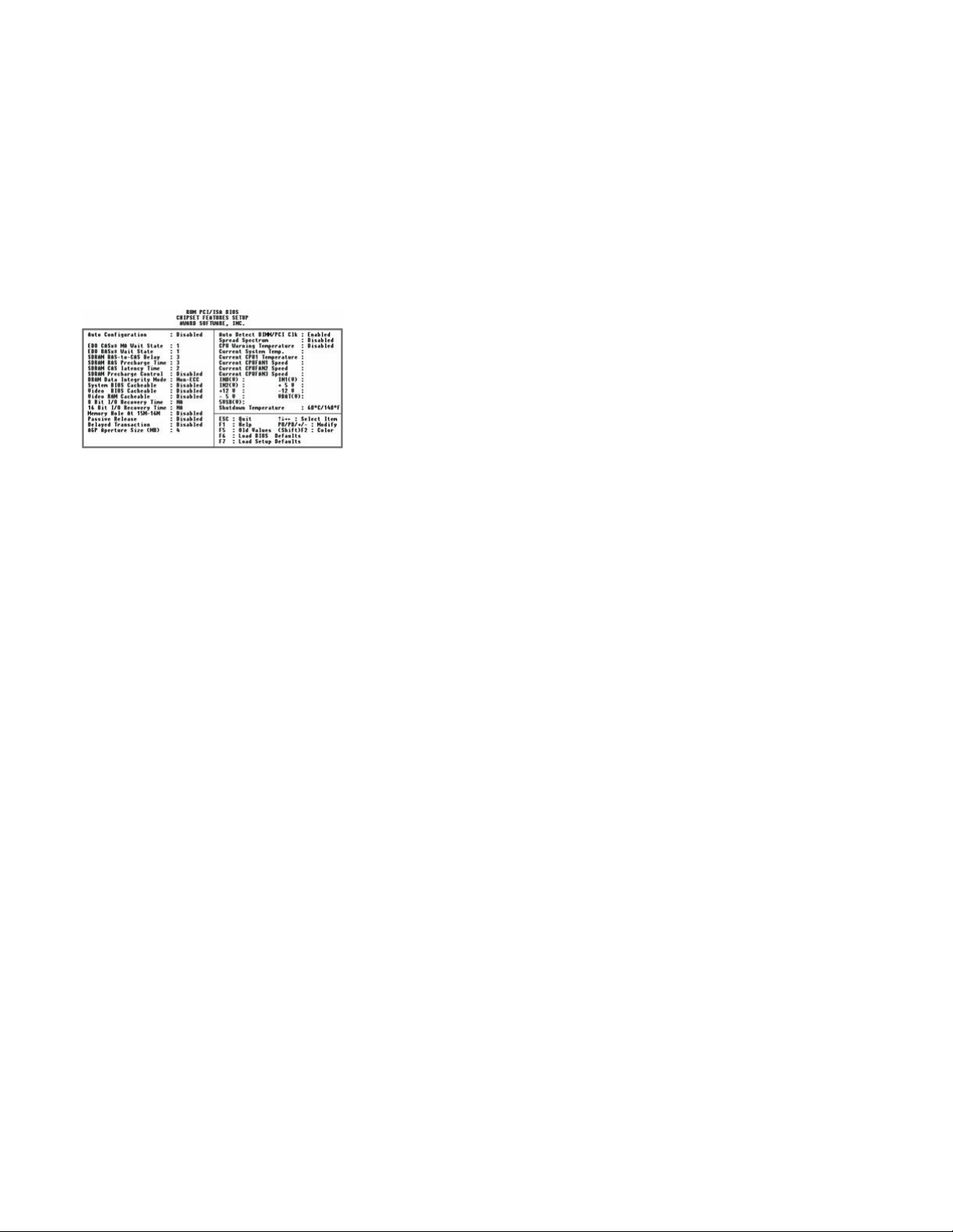
1. Choose �CHIPSET FEATURES SETUP� from the Main Menu, and the following figure appears on the screen :
Figure 3-4
2. Use one of the arrow keys to move between options and modify the
selected options by using PgUp/PgDn/+/- keys.
A short description of screen options (Figure 3-4) follows :
Auto
Configuration
Enabled this option (strongly
recommended) and the system
automatically sets all options on
the left side of the screen (except
cache update mode & BIOS
cacheable).
EDO CASx# MA
Wait State
Use the default setting.
EDO RASx#
Wait
State
Use the default setting.
SDRAM RAS-toCAS
Delay
Use the default setting.
SDRAM RAS
Precharge Time
Use the default setting.
SDRAM CAS
Latency Time
Use the default setting.
SDRAM
Precharge
Control
Use the default setting.
DRAM Data
Integrity Mode
Choose Non-ECC (default) or ECC
according to the DRAM type you
have.
System BIOS
Cacheable
Disabled : The ROM area F0000H-
FFFFFH is not cached.
Enabled : The ROM area F0000H-
FFFFFH is cacheable if cache
controller is enabled.
Video BIOS
Cacheable
Disabled : The video BIOS
C0000H-C7FFFH is not cached.
Enabled : The video BIOS
C0000H-C7FFFH is cacheable if
cache controller is enabled.
Video RAM
Cacheable
Use the default setting.
8 Bit I/O
Recovery Time
Use the default setting.
16 Bit I/O
Recovery Time
Use the default setting.
Memory Hole Choose Enabled or Disabled
Page 12

At 15M-16M (default). Some interface cards will
map their ROM address to this
area. If this occurs, you should
select Enabled, otherwise use
Disabled.
Passive Release Use the default setting.
Delayed
Transaction
Use the default setting.
AGP Aperture
Size
(MB)
AGP could use the DRAM as its
video RAM. Choose the DRAM
size that you want it to be used as
video RAM. The range is from
4MB to 256MB.
CPU Warning
Temperature
Choose Disabled (default) or
Enabled. Set CPU temperature
from 50�C to 70�C. The system will slow
down automatically when CPU temperature goes
beyond the preset value. CPU will continue to run
slow until the CPU temperature returns back within
the safe range.
Current System
Temp
Show the current temperature of
the system.
Current CPU1
Temperature
Show the current status of CPU.
3-5 Power Management Setup
Power Management Setup sets the system instructions power saving
functions.
1. Choose �POWER MANAGEMENT SETUP� from the Main Menu, and the following figure appears on the screen :
Figure 3-5
2. Use one of the arrow keys to move between options and modify the
selected options by using PgUp/PgDn/+/- keys.
A short description of screen options (Figure 3-5) follows :
ACPI function
Power
Management
Choose Max, Saving, User Define,
Disabled (default), or Min. Saving.
PM Control by
APM
Choose Yes (default) or No.
Choose Yes if the operating
system has APM functions, choose
No otherwise.
Video Off
Method
Choose Blank Screen (default),
DPMS, or V/H Sync+Blank. You
can choose either DPMS or V/H
Sync+Blank when the monitor has
the Green function. Choose Blank
when the monitor has no Green
function.
Video Off After Choose NA, Suspend, Standby
(default), or Doze.
Modem Use IRQ Assign the IRQ number to the
modem which is being used so
that the ring signal can wakeup the
system. The default setting is 3
(COM2).
Doze Mode This option sets the CPU speed
down to 33 MHz to conserve
power.
Standby Mode Standby Mode turns off the VGA
monitor, choose a mode for the
different times.
Suspend Mode Suspend Mode turns off the CPU,
thus saving the energy of the
systems.
HDD Power
Down
When the set time has elapsed,
the BIOS sends a command to the
HDD to power down.
Throttle Duty
Cycle
Choose the duty cycle time :
12.5%, 25%, 37.5%, 50%, 62.5%
(default), 75%. The bigger the
percentage, the more power
saving.
PCI/VGA Enabled : The system can not
enter the power saving mode when
Page 13

Act-Monitor monitor is on.
Disabled : The system can enter
the power saving mode when
monitor is on.
Soft-Off by
PWR-BTTN
Instant-off : (default) turns off the
system power at once after
pushing at once after pushing the
power button.
Delay 4 Sec : turns off the system
power 4 seconds after pushing the
power button ( to meet PC97/98
spec.).
IRQ 8
Break Suspend
You can Enable or Disable
monitoring of IRQ8 so it does not
awaken the system from Suspend
mode.
The Choice : Enabled, Disabled.
IRQ (#), NMI Enabled : (default) The system can
not enter the power saving mode
when I/O ports or IRQ# is activated
Disabled : The system still can
enter the power saving mode when
I/O ports or IRQ# is activated.
3-6 PnP/PCI Configuration Setup
PnP/PCI Configuration Setup configures the PCI bus slots. Run the PnP/PCI
Configuration Setup as follows :
1. Choose �PNP/PCI CONFIGURATION SETUP� from the Main Menu, and the following figure appears on the screen :
���������������������������������������������������� ���������� Figure
3-6
2. Use one of arrow keys to move between options and modify the selected
options by using PgUp/PgDn/+/- keys.
A short description of screen options (Figure 3-6) follows :
PNP OS
Installed
Yes : OS supports Plug and Play
function.
No : (default) OS doesn�t support
Plug and Play function.
Resources
Controlled By
Choose Manual (default) or Auto.
The BIOS checks the IRQ/DMA
channel number on the ISA and
PCI card manually if you choose
Manual and the IRQ/DMA channel
number will be checked
automatically if you choose Auto.
Reset
Configuration
Data
Choose Enabled or Disabled
(default). Disabled retains PnP
configuration data in BIOS and
Enabled resets the PnP
configuration data in the BIOS.
IRQ-x assigned
to
DMA-x assigned
to
Legacy ISA : Manually assigns
IRQ/DMA to device.
PCI/ISA PnP : BIOS assigns
IRQ/DMA to device automatically.
Used MEM base
addr
Choose N/A (default) or ISA legacy
card to have the memory start at
the address.
Used MEM
Length
Choose 8K, 16K, 32K, or 64K.
With the above two functions,
users can define where the used
memory address is located and its
corresponding length of the legacy
area. BIOS will skip the UMB area
which is used by the legacy device
to avoid memory space conflict.
3. Press <ESC> and follow the screen instructions to save or disregard your
settings.
3-7 Load Setup Defaults
Page 14

Load Setup Defaults option loads the default system values to the system
configuration fields. If the CMOS is corrupted, the defaults are loaded
automatically. Choose this option, and the following message will appear :
Load Setup Defaults (Y/N) ? N
To use the Setup defaults, change the prompt to �Y� and press <Enter>.
3-8 Integrated Peripherals Setup
1. Choose �INTEGRATED PERIPHERALS SETUP� from the Main Menu, and the following figure appears on the screen :
Figure 3-7
2. Use one of the arrow keys to move between options and modify the
selected options by using PgUp/PgDn/+/- keys.
A short description of screen options follows :
IDE HDD
Block Mode
Choose Enabled (default) or
Disabled. If the hard disk size is
larger than 540MB, choose
Enabled.
IDE Primary
Master/Slave PIO;
IDE Secondary
Master/Slave PIO;
IDE Primary
Master/Slave UDMA;
IDE Secondary
Master/Slave UDMA
Choose Auto (default) or Mode
0~4. The BIOS detects the HDD
Mode type automatically when
select Auto. Set to a lower mode
other than Auto when the hard disk
becomes unstable.
On-Chip
Primary/Secondary
PCI IDE
Enabled (default) : Turns on the
on-board IDE function.
Disabled : Turns off the on-board
IDE function.
USB Keyboard
Support
This function enables or disables
the USB Keyboard function.
Power On Function Wake up the system by keyboard
or mouse.
KBC input clock Use the default setting.
Onboard FDC
Controller
Choose Enabled (default) or
Disabled.
Choose Disabled when you use an
ISA card with FDD function, or
choose Enabled to use the
onboard FDD connector.
Onboard Serial
Port1
Choose COM1/3F8 (default),
COM2/2F8, COM3/3E8,
COM4/2E8, or Disabled. Do not
set COM port 1 & 2 to the same
value except Disabled.
Onboard Serial
Port2
Choose COM1/3F8, COM2/2F8
(default), COM3/3E8, COM4/2E8
or Disabled.
UART Mode select Choose Normal (default), IrDA or
ASKIR.
IR Transmission
Delay
Enabled : Enabled delay when
transferring data.
Disabled : (default) Disabled delay
when transferring data.
Onboard ParallelPort Choose the printer I/O address :
378H/IRQ7 (default), 3BCH/IRQ7,
278H/IRQ5.
Parallel Port Mode Choose SPP (default). ECP+EPP ,
EPP or ECP mode. The mode
depends on the external device
connected to this port.
ECP Mode Use DMA Choose DMA3 (default) or DMA1.
Most sound cards use DMA1.
Check with your sound card
configuration to make sure that
there is no conflict with this
function.
Page 15

EPP Mode Select Choose EPP 1.7 (default) or EPP
1.9. EPP 1.9 supports hardware
handshake. This setting is
dependent upon your EPP device.
3. Press < ESC> and follow the screen instructions to save or disregard your
settings.
3-9 Supervisor/User Password
These two options allow you to set your system passwords. Normally, the
supervisor has a higher ability to change the CMOS setup option than the
user. The way to set up the passwords for both Supervisor and User are as
follows :
1. Choose �CHANGE PASSWORD� in the Main Menu and press <Enter>.
The following message appears :
�Enter Password :�
2. The first time you run this option, enter your password up to 8 characters
and press <Enter>. The screen does not display the entered characters.
3. After you enter the password the following message appears prompting
you to confirm the password :
�Confirm Password :�
4. Enter the same password �exactly� as you just typed again to confirm
the password and press <Enter>.
5. Move the cursor to �Save & Exit Setup� to save the password.
6. If you need to delete the password you entered before, choose the
Supervisor Password and press <Enter>. It will delete the password that you
had before.
7. Move the cursor to �Save & Exit Setup� to save the option you did,
otherwise the old password will still be there the next time you turn your
machine on.
8. Press <ESC> to exit to the Main Menu.
3-10 HDD Auto Detection
IDE HDD Auto Detection detects the parameters of an IDE hard disk drive
and automatically enters them to the Standard CMOS Setup screen.
The screen will ask you to select a specific hard disk for Primary Master after
you select this option. If you accept a hard disk detected by the BIOS, you
can enter �Y� to confirm and then press <Enter> to check next hard disk.
This function allows you to check four hard disks and you may press the
<ESC> after the <Enter> to skip this function and go back to the Main Menu.
3-11 Save & Exit Setup
Save & Exit Setup allows you to save all modifications you have specified
into the CMOS memory. Highlight this option on the Main Menu and the
following message appears :
SAVE to CMOS and EXIT (Y/N) ? Y
Press <Enter> key to save the configuration changes.
3-12 Exit Without Saving
Exit Without Saving allows you to exit the Setup utility without saving the
modifications that you have specific. Highlight this option on the Main Menu
and the following message appears :
Quit Without Saving (Y/N) ? N
You may change the prompt to �Y� and press The <Enter> key to leave
this option.
 Loading...