

Page 1

User's Manual Version 1.0
The information presented in this publication has been made
carefully for reliability; however, no responsibility is assumed
for inaccuracies. Specifications are subject to change without
notice.
IBM, PC/AT, and PC/XT are trademarks of International Busi-
ness Machines Corporation.
Pentium is a trademark of Intel Corporation
AWARD is a registered trademark of Phoenix Sofftware Inc.
MS-DOS and WINDOWS NT are registered trademarks of
Microsoft Corporation.
Trademarks and/or registered trademarks are the
properties of their respective owners.
Page 2

Table of Contents
Chapter 1 Introduction ................................................ 1
How this manual is organized .............................1
Package checklist ................................................ 2
Chapter 2 Features ...................................................... 3
Features of the mainboard ........................ 3
The mainboard layout ............................... 6
Chapter 3 Installation ................................................... 8
System Installation Setups ...................... 10
Static Electricity Precaution .................... 10
Jumper Settings ........................................ 11
System Memory (DIMM modules) ............ 13
DIMM Memory Installation ........................ 14
CPU Installation ........................................ 16
Clearance Requirements .......................... 17
Fan Exhaust .............................................. 17
External Connectors ................................ 18
Chapter 4 BIOS Setup ............................................... 27
Page 3

Chapter 1
1
Introduction
How This Manual is Organized
This manual is divided into the following sections:
Chapter 1 Introduction : Manual information and checklist.
Chapter 2 Features : Information and Specifications con-
cerning this mainboard.
Chapter 3 Installation : Instructions on setting up the board.
Chapter 1 Introduction / 1
Page 4

Package Checklist
Please check that your package is complete . If you discover any item
damaged or missing , please contact with your retailer immediately.
The 6A815E mainboard.
1 x IDE UDMA66 ribbon cable.
1 x COM2 cable.
1 x Floppy ribbon cable.
6A815E support software:
CD driver and utilites.
This user's Manual
2 / Chapter 1 Introduction
Page 5

Chapter 2
2
Features
Features of the 6A815E Mainboard
The 6A815E is designed for the PC user who want many new key
features processed by the fastest CPU in a economic package. This
mainboard :
New general CPU support :
- Socket 370 for Intel PPGA/FC-PGA PII/PIII processor.
- Socket 370 Celeron (300MHz~733MHz) or higher
processor.
- Socket 370 VIA Cyrix III 500~600MHz processor.
- Socket 370 Coppermine (500MHz~1GHz) or higher
processor.
3 / Chapter 2 Features
Page 6

Chipset :
-GMCH Chipset :Intel 815 support a 66/100/133 FSB.
-ICH Chipset :Intel ICH2.
Biggest memory capacity :
6A815E is equipped with three DIMM socket to support
(16MB, 32MB, 64MB, 128MB.256MB) 168 pin 3.3v
SDRAM SPD(Special Presence Detect).Maximum
memory up to 512MB.
-Supports up to 3 double sided DIMMs at 100MHz
system memory bus.
-Supports up to 2 double sided or 3 single sided
DIMMs at 133MHz system memory bus.
AGP for fast VGA solution :
-AGP specification compliant.
-AGP 66 MHz 3.3v/1.5v for 1X/2X/4X device support.
PCI Expansion Slot :
Provide five 32 bit PCI slots.
On-Board IDE :
-An IDE controller on the ICH2 chipset provides IDE HDD/
CD-ROM with PIO,Bus Master and Ultra DMA 33/66/100
operation modes.
-Can connect up to four IDE device.
On-Board Peripherals:
-1 floppy port supports 2 FDD with 360K,720K,1.2M, 1.
44M and 2.88M byte.
-2 serial ports (COM1+COM2 (10pin )).
-4 USB ports.
-1 VGA ports.
-1 parallel port supports SPP/EPP/ECP mode.
-1 RJ-45 connector. (option)
Audio:
- ICH2 chip integrated.
- AC’97 CODEC on board ,support 3D sound effect.
4 / Chapter 2 Features
Page 7

BIOS:
- The mainboard BIOS provides “Plug & Play” BIOS which
detects the peripheral devices and expansion cards of the
board automatically.
- The mainboard provides a Desktop Management Interface
(DMI) function which records your mainboard
specifications.
- BIOS support CD-ROM, SCSI, LAN BOOT,Temperature
sensor, Wake on modem, LAN, Alarm Bus CLK setup with
BIOS.
Intel Accelerated Hub Architecture :
Features a dedicated high speed hub link between the ICH2
and GMCH with a bandwidth of 266MB/sec-twice the maximum bandwidth of the PCI bus.
CNR Support :
Two Communication and Networking Riser(CNR) slots
provide interface to support very affordable multichannel
audio,V.90 analog modem, Home PNA, 10/100 Ethernet
networking,USB hub, as well as future technologies such
as XDSL .
Fan Status Monitoring and Alarm Temperature Monitor-
ing/Voltage Monitoring and Alert.
Integrated Graphics :
Controller supports 3D hyper pipelined architecture,
parallel data processing and compression,precise pixel
interpolation, full 2D hardware acceleration,and motion
video acceleration.
5 / Chapter 2 Features
Page 8

Support Ring on by modem/Alarm on :
Support System power up from Modem ring up or timer
of System. Required enabled in Ring on by modem and
Alarm on in BIOS.
PC Health Monitoring :
Provides an easy way to examine and manage system
status information, such as CPU and system voltages,
temperatures, and fan status through the onboard hardware.
Suspend and Go :
Suspend-to-RAM (str) provides maximum power savings
as an alternative to leaving the computer ON and Quickstart
so that you do not have to wait for a long time for system
boot.
Dual Function Power Button :
Through BIOS, the power button can be defined as the
“Stand by” button or as the Soft-Off button.
6 / Chapter 2 Features
Page 9
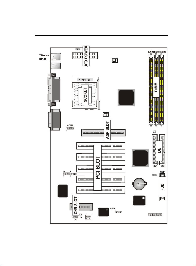
The 6A815E Mainboard layout
JP7
FAN3
T:R J-4 5
B:USB1/2
COM1
Printer
VGA
Intel
JACK1
JACK2
JACK3
GAME1
LAN CHIP
CNR SLOT
FAN2
BIOS
FAN1
PCI SLOT1
PCI SLOT2
PCI SLOT3
PCI SLOT4
PCI SLOT5
JP4
AGP1
Intel
I/O CHIP
IR
7 / Chapter 2 Features
LED1
JP6
1
J6
Page 10

Chapter 3
3
Installation
Jumper
Jumper Refer to page
J P6 - Real time Clock RTC Clean 12
J 6 - HD_ LED 23
J 6 - Reset Switch 23
J 6 - Power LED 23
J 6 - Speaker Connector 24
J 6 - ATX Power Switch 2 4
J P4 - BIOS Flash Jumper 25
J P7 - Keyboard Wake up Setting 26
J 8 - CNR Card Use Setting 26
8 / Chapter 3 Installation
Page 11

Expansion Slot
168 pin DIMM Socket 13
Socket 370 16
AGP (Accelerator Graphic Port) SLOT 18
PCI SLOT 1,2,3,4,5 -32bits PCI SLOT 1 8
CNR(Communication and Networking Riser) SLOT18
Which page
Connectors Refer to page
KB1(DP) - PS/2 Keyboard port 19
KB1(UP) - PS/2 Mouse port. 19
USB - USB1,2,3,4 Port 19
COM1 - COM 1 serial port (9 pin) 19
COM2 - Serial port COM 2 Header(1-10pin) 19
LPT1 - Parallel port 19
VGA - Moniter output connector (15 pin) 20
RJ-45 - LAN connector 20
FDD1 - FLOPPY connector 20
IDE1 - Primary IDE connector 20
IDE2 - Secondary IDE connector 20
FAN1 - FAN CONN. for CPU 21
FAN2 - FAN CONN. for SYS 21
FAN3 - FAN CONN. for MB 21
IR - IrDA connector 22
PW1 - ATX Power Connector 24
CN1 - CD Audio connector 25
LED1 - STR LED 26
Chapter3 Installation / 9
Page 12

System Installation Setup
Before using your computer, you must finish the following steps:
1. Set jumpers on mainboard
2. Install SDRAM module.
3. Install the Processor.
4. Connect Ribbon Cables, Cabinet Wires, and Power supply.
5. Install Add on Cards.
6. Setup the BIOS software.
7. Make sure your ATX Power Supply the 5VSB output has 1
Ampere or more.
8. First turn off the ATX Power Supply when you setup the
SDRAM Module.
Static Electricity Precaution
Keep the mainboard and other system components in their anti-
static packaging until you are ready to install them.
Do all preparative work on a static-free surface with the main
board components facing up.
Unplug your computer when working on the inside.
Wear an Anti-static wrist strap.
Hold the system components, boards or cards by its edges only.
Be careful not to touch any of IC chips, circuitry, contacts or
connections, especially gold contacts on the mainboard.
10 / Chapter 3 Installation
Page 13

Jumper Settings
Jumpers
Several hardware setting are made through the use of jumper caps to
connect jumper pins (Jxx) on the mainboard. See " Map of the
mainboard" for locations of jumpers.
The jumper settings will be described numerically such as [----], [1-2],
[2-3] for no connection, connect pins 1 & 2, and connect pins 2 & 3
respectively. Pin 1 for our mainboard is always on top one or on the
left when holding the mainboard with the keyboard away from
yourself. "P1" is written besides pin 1 on jumper with three pins. The
jumpers will also be shown graphically such as to connect pin
1&2 and to connect 2&3. Jumpers with two pins will be shown
as for Short (on )and for Open (off).For manufacturing
simplicity it may be sharing pins from other groups. Use the diagrams
in this manual instead of following the pin layout on the board. Settings with two jumper numbers require that both jumpers be moved
together. To connect the pin, simply place a plastic jumper cap over
the two pins as diagrammed.
Chapter3 Installation / 11
Page 14
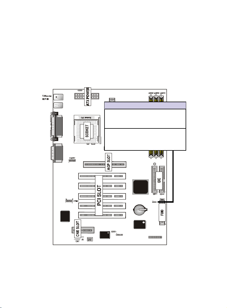
Real Time Clock (RTC) RAM - JP6 :
The CMOS RAM is powered by the onboard button cell battery. To
clear the RTC data:
(1)Turn off your computer, (2) Move this jumper to "2-3Pin Clear
Data", (3) Move the jumper back to "Default", (4) Turn on your
computer, (5) Hold down <Delete > during bootup and enter BIOS
setup to re-enter user Preferences.
T:R J- 45
B:USB1/2
COM1
VGA
JACK1
JACK2
JACK3
Printer
GAME1
LAN CHIP
JP7
CNR SLOT
FAN2
FAN3
JP6 CMOS Clear
[1-2] Normal (Default)
PCI SLOT1
PCI SLOT2
PCI SLOT3
PCI SLOT4
PCI SLOT5
JP4
AGP1
Intel
IR
Intel
I/O CHIP
LED1
JP6
1
J6
[2-3] Enabled (Clear CMOS)
FAN1
BIOS
12 / Chapter 3 Installation
Page 15
System Memory ( DIMM Module)
This 6A815E main board supports three 168 pin DIMM of 16 MB,
32 MB, 64 MB, 128 MB ,256MB to form a memory size between
16MB to 256MB.
The DRAM can be either 45ns,50ns,or60ns SDRAMs.
Install memory in any or all Banks in Combination:
Note:
-Supports up to 3 double sided DIMMs at 100MHz
system memory bus.
-Supports up to 2 double sided or 3 sided DIMMs at
133MHz system memory bus.
Bank Memory module
DIMM 1 16MB,32MB,64MB,128MB,256MB
( Bank 0-1 ) 168 pin,3.3v SDRAM
DIMM 2 16MB,32MB,64MB,128MB,256MB
( Bank 2-3 ) 168 pin 3.3v,SDRAM
DIMM 3 16MB,32MB,64MB,128MB,256MB
( Bank 4-5 ) 168 pin 3.3v,SDRAM
Total System Memory(Max 512MB)
Note :
The DIMM Slot does not support any 5V EDO DIMM
module.
The DIMM Slot does not support any 5V SDRAM
DIMM module.
Memory speed setup is required through "Auto Con-
figuration" in BIOS chipset Setup of BIOS SOFTWARE.
If several speed memories are used, You must set Auto
Configuration to low. Example If both 50ns, 60ns are
used, Please set Auto configuration to 60ns.
It's allowed any DIMM module put in any DIMM slot.
It's allowed there are different capacity DIMM module
in all DIMM slot.
Please shut down the ATX Power when you setup the
DIMM Module.
Chapter3 Installation / 13
Page 16
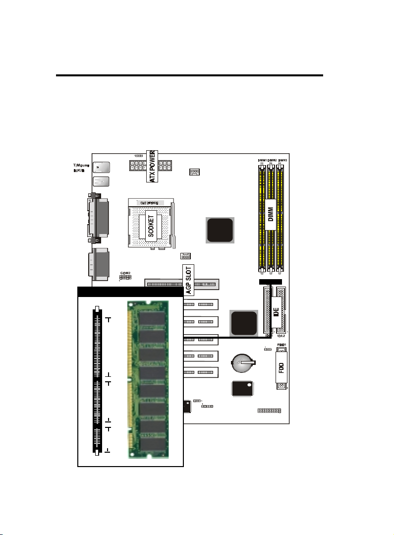
DIMM Memory Installation
Insert the module (s) as shown. Because the number pins are different on either side of the breaks,the module will only fit in the orientation as shown. SDRAM DIMM modules have different pin contacts on each side and therefore have a higher pin density.
JP7
T:R J- 45
B:USB1/2
COM1
Printer
VGA
JACK1
JACK2
JACK3
GAME1
168 Pin DIMM Socket
88 pins
LAN CHIP
60 pins
20 pins
CNR SLOT
FAN2
BIOS
FAN1
FAN3
JP4
AGP1
PCI SLOT1
PCI SLOT2
PCI SLOT3
PCI SLOT4
PCI SLOT5
Intel
IR
Intel
I/O CHIP
LED1
JP6
1
J6
14 / Chapter 3 Installation
Page 17
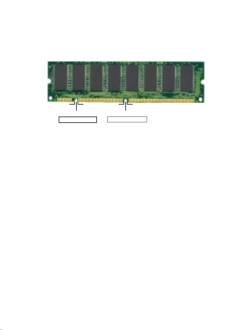
The Dual Inline Memory Module (DIMM) memory module must
be 3.3v . You can identify the type of DIMM module by the illustration below:
RFU Unbuffered
Buffered
DRAM Key Position
5.0V Reserved
3.3V
Voltage Key Position
168 Pin DRAM DIMM Notch Key Definitions
The notch on the DIMM module will shift between left, center, or
right to identify the type and also to prevent the wrong type to be
inserted into the DIMM slot on the Mainboard. You must ask your
retailer for Specifications before purchasing.
Four clock signals are supported on this mainboard
Chapter3 Installation / 15
Page 18
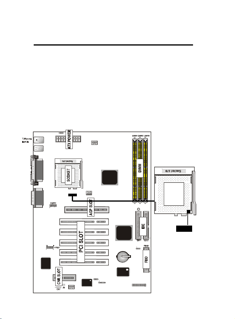
CPU Installation
The motherboard provides a ZIF socket 370. The CPU that came
with the motherboard should have a fan attached to it to prevent
overheating . If this is not the case then purchase a fan before you
turn on your system.
To install a CPU , first turn off your system and remove its cover.
Locate the ZIF socket and open it by first pulling the lever sideways
away from the socket then upwards to a 90-degree right angle. Insert the CPU with the correct orientation shown . The notched corner should point towards the end of the lever. Because the CPU has
a corner pin for two of the four corners, the CPU will only fit in the
orientation as shown.
T:R J- 45
B:USB1/2
COM1
VGA
JP7
Printer
FAN3
Intel
JACK1
JACK2
JACK3
GAME1
LAN CHIP
CNR SLOT
FAN2
BIOS
FAN1
PCI SLOT1
PCI SLOT2
PCI SLOT3
PCI SLOT4
PCI SLOT5
JP4
AGP1
LED1
Intel
JP6
I/O CHIP
IR
1
J6
Notch
16 / Chapter 3 Installation
Page 19

Selecting the CPU Frequency
CPU voltage auto-detection and allow user to set CPU frequency
through BIOS setup, no jumper or switch is needed. The correct
CPU information is saved into EPROM, with these technologies,
the disadvantages of Pentium base jumper-less design are eliminated.
There will be no worry of wrong CPU voltage detection and no need
to re-open the housing if CMOS battery loss. The CPU frequency
selection is set by going into:
Choose “CPU SPEED SETTING” from the BIOS and a screen with
frequency/voltage control items appears.
CPU Clock Ratio
This item lets you select the ratio of Core/Bus frequency. Have
the following selection: 3x, 3.5x, 4x, 4.5x, 5x, 5.5x, 6x, 6.5x,
7.0x, 7.5x,8.
CPU Host/PCI Clock/PC133
This item lets you set external clock (bus clock). The possible
settings are 66,100 and 133 MHZ....
Clearance Requirements
To maintain proper airflow once the processor is installed on the
mainboard, the processor and fan heatsink require certain space
clearances. The clearance above the processor must be at least 0.3
inches. The clearance on at least 3 of 4 sides of the processor and
fan heatsink must be at least 0.2 inches. All cables (for Floppy drive,
Hard drive,CD-ROM,and so on) must be routed clear of the processor and its airspace.
Fan Exhaust
The processor must be kept cool by using a processor with heatsink
and fan attached . The temperature of the air filled with the fan/
heatsink cannot exceed 45 OC(113 OF ) . The ambient or room temperature must be below 37 OC ( 99 OF) .
Chapter3 Installation / 17
Page 20
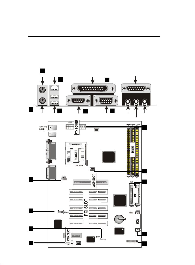
EXTERNAL CONNECTORS
Both Ribbon cable and Connectors on board are with direction signs
to avoid that user insert wrong directions. On the other hand, the
ribbon cables should always be connected with the red stripe on the
pin 1 of side of the connector.
2
PS/2 Mouse
RJ-45 (option)
7
Parallel (Printer) Port
(25-pin Female)
4
MIDI/(GAME) Port
(15-pin Female)
1
PS/2 Keyboard
(6-pin Female)
T:RJ -45
B:USB1/2
COM1
VGA
JACK1
JACK2
JACK3
3
5
USB1/2
JP7
Printer
GAME1
COM2
5
USB3/4
IR Port
11
CD Audio
Connector
LAN CHI P
14
18 / Chapter 3 Installation
COM1
CNR SLOT
FAN2
3
Serial Port
FAN1
BIOS
FAN3
JP4
VGA
AGP1
PCI SLOT1
PCI SLOT2
PCI SLOT3
PCI SLOT4
PCI SLOT5
Intel
IR
6
I/O CHIP
SPEAKER
Intel
1
LINE IN
LED1
JP6
J6
MIC
13
ATX Power
Connector
FAN 1,2,3
10
Connector
9
IDE Connector
Floppy
Driver Connector
8
PANEL
12
Page 21
1. PS/2 Keyboard port
This connection is for a standard keyboard using an PS/2 plug
(mini DIN) . This connector will not allow standard at AT size
(large DIN) keyboard plugs. You may use a DIN to mini DIN
adapter on standard AT keyboards.
2. PS/2 Mouse port
This system will direct IRQ12 to PS/2 mouse.
3. Serial Port COM 1 and COM 2 port
The one serial ports can be used for pointing devices or other
serial devices. See "Onboard Serial Port" in chipset Feature Setup
of the BIOS SOFTWARE.Serial port COM 2 Header(1-10pin).
NOTE:
Serial {D-type 9pin (F) } must be connected to the
serial port.
4. Parallel Printer port
You can enable the parallel port and choose the IRQ through "
Onboard Parallel Port" in Chipset. Feature Setup of the BIOS
SOFTWARE.
5. - Universal Serial BUS Ports 1,2
Two USB ports are available for connecting USB devices.
- Universal Serial BUS Ports 3,4
Two USB ports are available on the back panel.Therefore,we
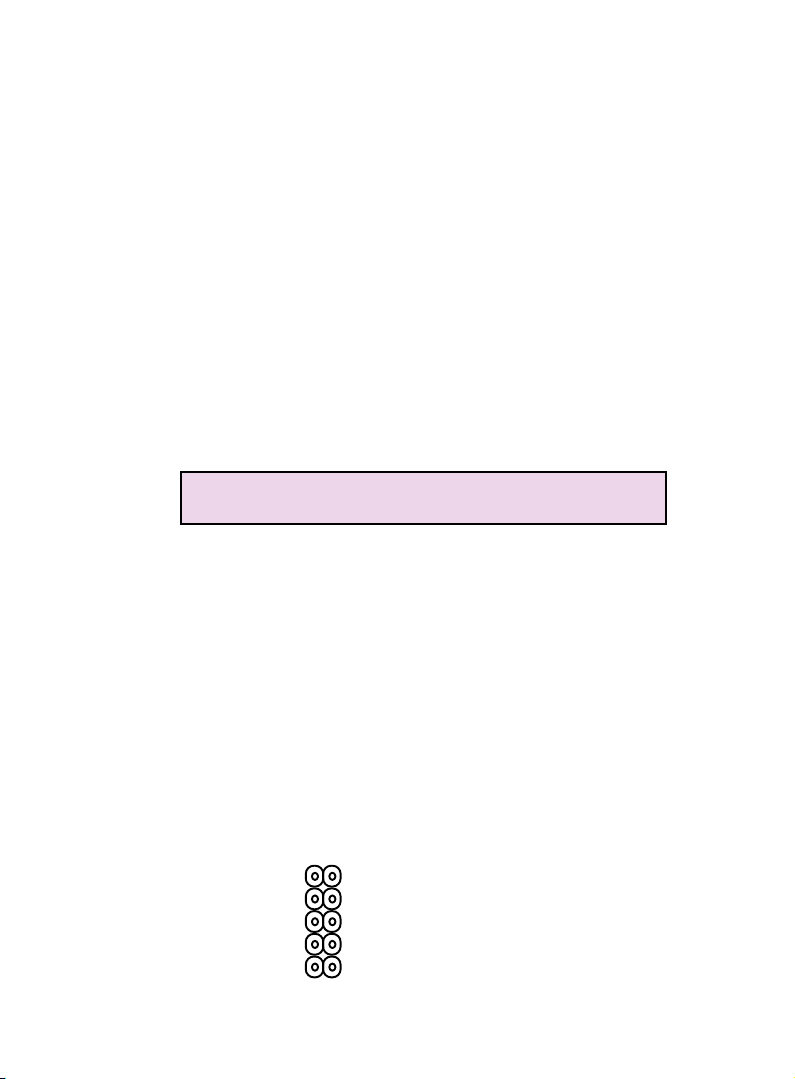
provide a 10 pin ribbon cable with bracket to connect Builtin on-board USB header.
USB 3,4
1
VCC
P0-
P0+
GND
10
2
3
4
5
9
GND
8
P1+
7
P1-
6
VCC
Chapter3 Installation / 19
Page 22

6. VGA Connectors (15-pin)
This connectors support monitor.
7. RJ-45 Connector (option)
Onboard 10/100MB PCI Fast Ethenet Network.
The RJ-45 connectors at the time of purchase and is located on
top of the USB connectors.The connector allows the
motherboard to connect to a Local Area Network (LAN) through
a network hub .
8. Floppy drive connector
This connector supports the provided floppy drive ribbon cable.
After connecting the single end to the board, connect the two
plus on the other end to the floppy drives.
9. Primary / Secondary IDE connectors (Two 40-pin Blocks)
These connectors support the provided IDE hard disk ribbon
cable. After connecting the single end to the board, connect the
two plugs at the other end to your hard disk no space(s) . If you
install two hard disks, you must configure the second drive to
Slave mode by setting its jumper settings. BIOS now supports
SCSI device or IDE CD-ROM boot up (see "HDD Sequence SCSI/
IDE First" & "Boot Sequence" in the BIOS Features Setup of the
BIOS SOFTWARE) (Pin 20 is removed to prevent inserting in
the wrong orientation when using ribbon cables with pin 20
plugged) .
Tip :
You may configure two hard disks to be both Master
using one ribbon cable on the primary IDE connector.
You may install one operating system on an IDE drive
and another on a SCSI drive and select one of the two
through BIOS Feature Setup.
20 / Chapter 3 Installation
Page 23
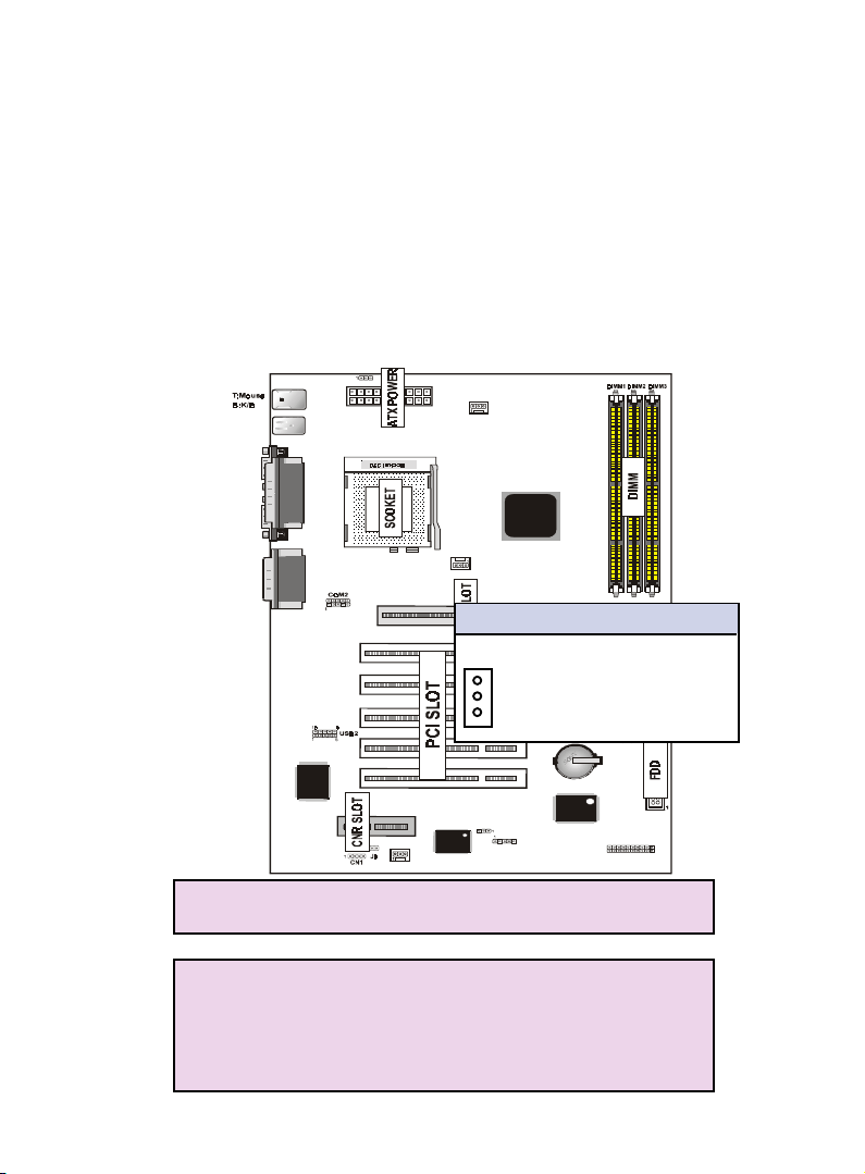
10. FAN1 , FAN2 , FAN3 CPU Cooling Fan (FAN/PWR)
These connectors support cooling fans of 500mAmp
(6Watt) or less. Orientate the fans so that the heatsink
fins allow airflow to go across the onboard heat sink(s)
instead of the expansion slots. Depending on the fan
manufacturer, the wiring and plug may be different. The
red wire should be positive, while the black should be
ground. Connect the fan’s plug to the board taking into
consideration the polarity of this connector.
T:RJ -4 5
B:USB1/2
COM1
VGA
JP7
Printer
FAN3
Intel
NOTE :
JACK1
JACK2
JACK3
GAME1
LAN CHIP
CNR SLOT
FAN1
AGP1
FAN1/2/3 CPU Cooling FAN
PCI SLOT1
Pin Description
PCI SLOT2
1 Ground
P1
P2
2 +12VDC
PCI SLOT3
P3
3 Signal
PCI SLOT4
PCI SLOT5
JP4
BIOS
FAN2
IR
Intel
I/O CHIP
LED1
JP6
1
J6
The "Rotation" signal is to be used only by a specially
designed fan with rotation signal.
WARNING :
The CPU and/or motherboard will overheat if there is
no air flowing across the CPU and onboard heatsinks.
Damage may occur to the motherboard and/or the CPU
fan if these pins are incorrectly used. These are not
jumpers, do not place jumper caps over these pins.
Chapter3 Installation / 21
Page 24
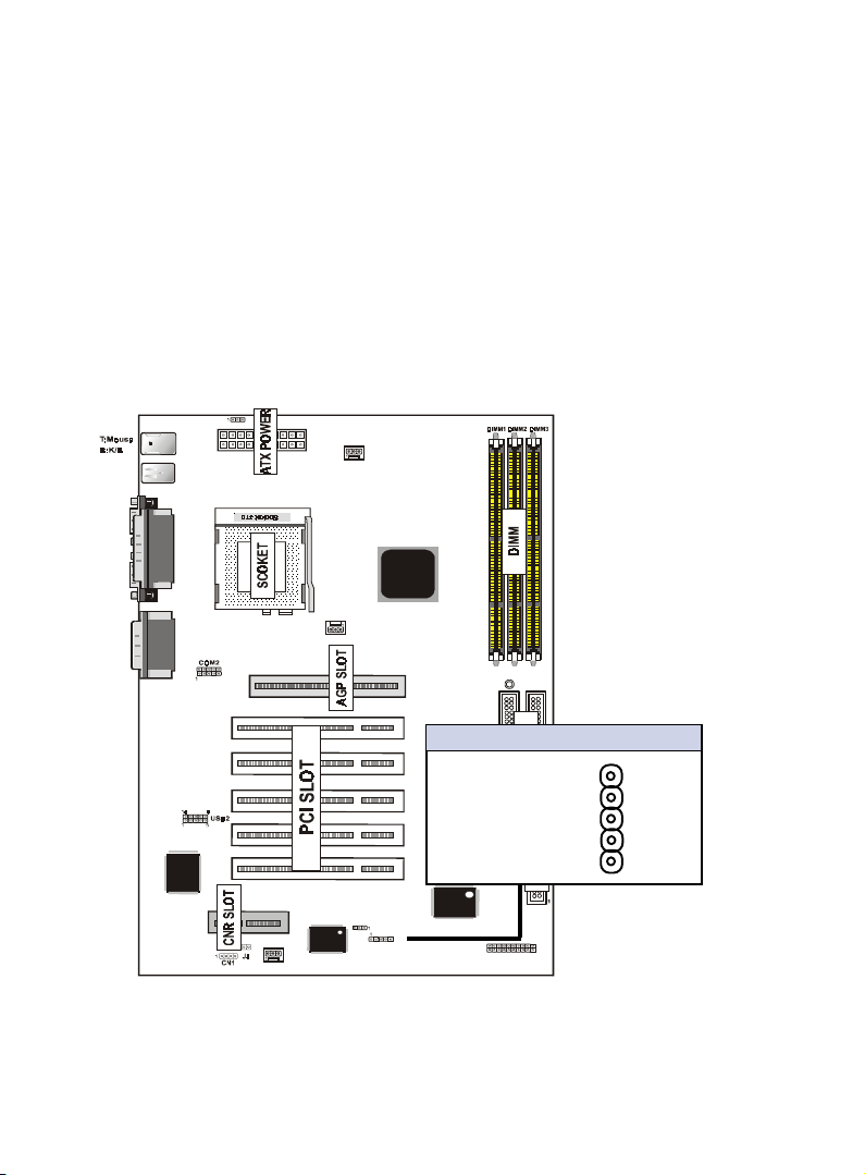
11. IrDA / Fast IR-Compliant infrared module connector - IR
This connector supports the optional wireless transmitting and
receiving infrared module. This module mounts to a small opening on system cases that support this feature. You must also
configure the setting through UART2 Use Infrared” in Chipset
Feature Setup to select whether UART2 is directed for use with
COM2 or IrDA. Use the five pins as shown on the Back View
and connect a ribbon cable from the module to the motherboard
according to the pin definitions.
T:RJ -45
B:USB1/2
COM1
VGA
JACK1
JACK2
JACK3
Printer
GAME1
LAN CHI P
JP7
CNR SLOT
FAN2
BIOS
FAN3
Intel
FAN1
AGP1
PCI SLOT1
PCI SLOT2
PCI SLOT3
PCI SLOT4
PCI SLOT5
Pin Description
LED1
IrDA/Fast IR Connector
Intel
1 VCC
2 IR4_MODE
JP6
3 IRRXA
4 GND
1
5 IRTXA
I/O CHIP
JP4
IR
1
J6
22 / Chapter 3 Installation
Page 25
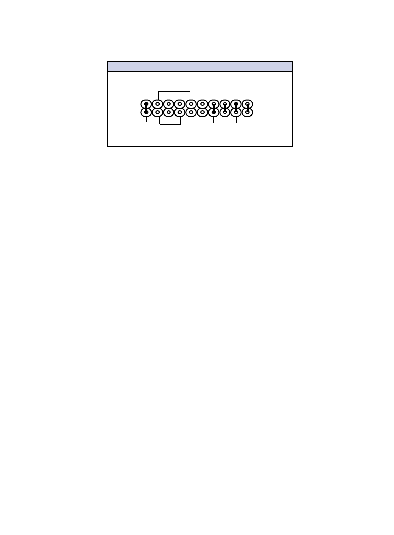
12.J6
J6 PANEL Connector
SPEAK
+
2
1
+
PW_BN
PW_LED
+
HD_LED
RST
a. IDE activity LED (HD-LED)
This connector supplies power to the cabinet’s IDE activity LED.
Read and write activity by devices connected to the Primary or
Secondary IDE connectors will cause the LED to light up.
b. Power LED Lead (PW_LED)
The system power LED lights when the system’s power is on.
c. Reset Switch Lead (RST)
This 2-pin connector connects to the case-mounted reset switch
for rebooting your computer without having to turn off your
power switch. This is a preferred method of rebooting in order
to prolong the life of the system's power supply.
d. Speaker Connector (SPEAKER)
This 4-pin connector connects to the case-mounted speaker.
e. ATX Power Switch (PW_BN)
The system power is controlled by a momentary switch connected to this lead. Pushing the button once will switch the system ON. The system power LED lights when the system's power
is on.
Chapter3 Installation / 23
Page 26
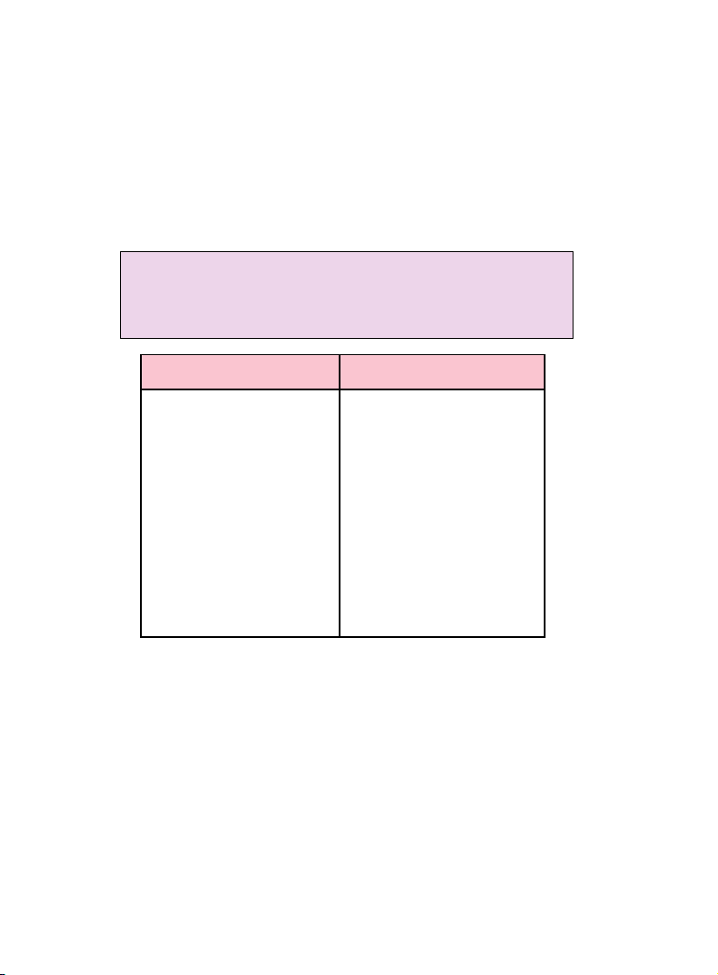
13. ATX Power Supply Connector (20-pin block) - PW1
This connector connects to a ATX power supply. The plug from
the power supply will only insert in one orientation because of
the different hole sizes. Find the proper orientation and push
down firmly making sure that the pins are aligned.
IMPORTANT:
Make sure that the ATX power supply can take at least
10mAmp load on the 5Volt standby lead (5VSB). You may
experience difficulty in powering on your system without this.
Pin Description Pin Description
1 3.3V 2 3.3V
3 GND 4 5V
5 GND 6 5V
7 GND 8 PW-OK
9 5VSB 10 12V
1 1 3.3V 12 -12V
13 GND 14 PS-ON
15 GND 16 GND
17 GND 18 -5V
19 5V 20 5V
24 / Chapter 3 Installation
Page 27
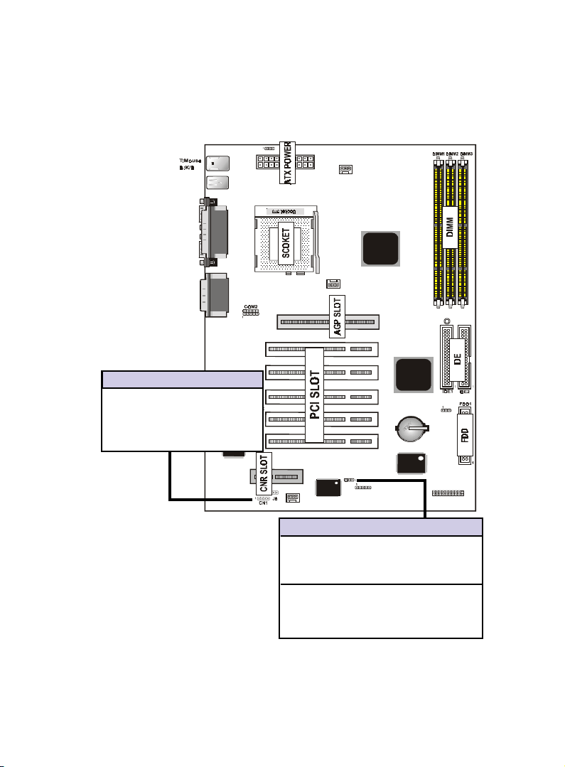
14. CD Audio Connector- CN1
The 4-pin connectors enable the system to receive the audio
output from the CD-ROM.
T:RJ -45
B:USB1/2
COM1
VGA
JACK1
JACK2
JACK3
CN1 Description
1 CD-R
2 GND
3 GND
4 CD-L
Printer
GAME1
JP7
LAN CHIP
CNR SLOT
FAN2
BIOS
FAN3
Intel
FAN1
PCI SLOT1
PCI SLOT2
PCI SLOT3
PCI SLOT4
PCI SLOT5
JP4
AGP1
I/O CHIP
IR
Intel
LED1
JP6
1
J6
JP4 BIOS Boot Block Flash
[1-2] UnLocked (Default)
[2-3] Locked
15.BIOS Boot Block Flash Jumper-JP4
The Jumper is used to locked/unlocked BIOS Boot Block Flash.
This Jumper should be unlock when flashing/programming the
BIOS.
Chapter3 Installation / 25
Page 28
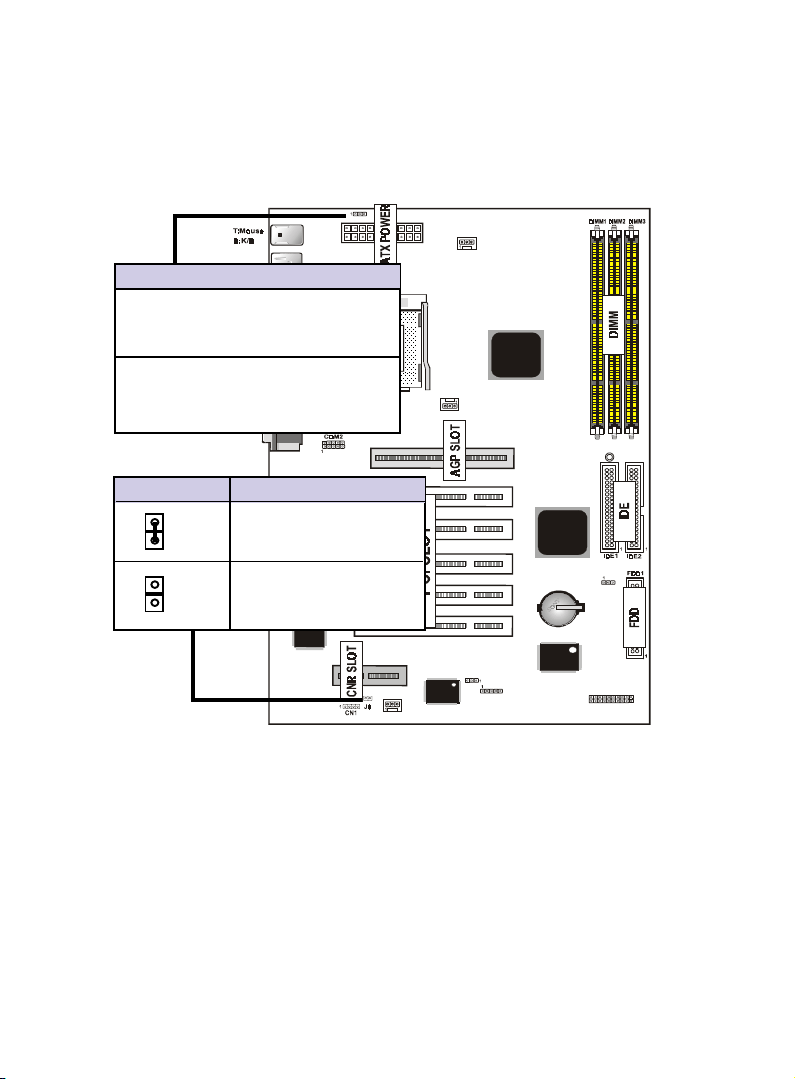
16. Keyboard Wake up Setting- JP7
The Jumper is used to Keyboard boot setting.
JP7
T:RJ -45
JP7 Keyboard Wake up Setting
[1-2] Disabled
B:USB1/2
COM1
Printer
VGA
[2-3] Enabled (Default)
Keyboard Boot
JACK1
JACK2
JACK3
GAME1
Pin J8 Assignment
Close:secondary
(Default)
Open :primary
LAN CHIP
CNR SLOT
BIOS
FAN2
17.CNR Card Use Setting-J8
The Jumper is used to CNR Card use setting.
FAN3
Intel
FAN1
PCI SLOT1
PCI SLOT2
PCI SLOT3
PCI SLOT4
PCI SLOT5
JP4
AGP1
IR
Intel
I/O CHIP
LED1
JP6
1
J6
18.STR LED-LED1
The LED is used to STR ON/OFF state.
26 / Chapter 3 Installation
Page 29

Chapter 4
4
Award BIOS
Setup
Introduction
This chapter discusses the Award Setup program built into
the ROM BIOS. The Setup program allows user to modify
the basic system configuration. This special information is
then stored in battery-backed RAM so that it retains the setup
information when the power is turned off.
Chapter 4 Award BIOS Setup / 27
Page 30

The Award BIOS installed in your computer system’s ROM
(Read Only Memory)is a custom version of an industry
standard BIOS. The BIOS provides critical low-level
support for standard devices such as disk drives and serial
and parallel ports.
The rest of this manual is intended to guide you through the
process of configuring your system using Setup.
Plug and Play Support
This AWARD BIOS supports the Plug and Play Version
1.0A specification. ESCD(Extended System Configuration
Data)write is supported.
EPA Green PC Support
This AWARD BIOS supports Version 1.03 of the EPA Green
PC specification.
APM Support
These AWARD BIOS supports Version 1.1&1.2 of the
Advanced Power Management(APM) specification. Power
management features are implemented via the System
Management Interrupt(SMI). Sleep and Suspend power
management modes are supported. Power to the hard disk
drives and video monitors can be managed by this AWARD
BIOS.
28 / Chapter 4 Award BIOS Setup
Page 31

PCI Bus Support
This AWARD BIOS also supports Version 2.1 of the Intel
specification.
DRAM Support
SDRAM (Synchronous DRAM) are supported.
Support CPU
This AWARD BIOS supports the Intel Celeron/Coppermine
PII/PIII Processor.
Using Setup
In general,you use the arrow keys to highlight items,press
<Enter>to select, use the <PgUp>and <PgDn>keys to
change entries, press<F1>for help and press <Esc>to quit.
The following table provides more detail about how to navi
gate in the Setup program by using the keyboard.
Chapter 4 Award BIOS Setup / 29
Page 32

Keystroke Function
Up arrow Move to previous item
Down arrow Move to next item
Left arrow Move to the item on the left(menu bar)
Right arrow Move to the item on the right(menu bar)
Esc Main Menu:Quit without saving changes
Submenus:Exit Current page to the next higher
level menu
Move Enter Move to item you desired
PgUp key Increase the numeric value or make changes
PgDn key Decrease the numeric value or make changes
+Key Increase the numeric value or make changes
-Key Decrease the numeric value or make changes
Esc Key Main menu-Quit and not save changes into
CMOS
Status Page Setup Menu and option Page Setup
Menu -Exit Current page and return to Main
Menu
F1 Key General help on Setup navigation keys.
F5 Key Load previous values from CMOS
F6 Key Load the fail-safe defaults from BIOS default
table
F7 Key Load the optimized defaults
F10 Key Save all the CMOS changes and exit
30 / Chapter 4 Award BIOS Setup
Page 33

4.1 Main Menu
Once you enter AWARD BIOS CMOS Set up Utility, the Main
Menu will appear on the screen. The Main Menu allows you
to select from several setup function. Use the arrow keys to
select among the items and press<Enter> to accept and
enter the sub-menu.
“WARNING”
The information about BIOS defaults on manual (Figure
1,2,3,4,5,6,7,8,9,10,11,12,13,14)is just for reference,please
refer to the BIOS installed on the board for update
information.
◎◎
◎ Figure 1. Main Menu
◎◎
CMOS Setup Utility-Copyright(C) 1984-2000 Award
Software
Standard CMOS Features Frequency/Voltage Control
Advanced BIOS Features Load Fail-Safe Defaults
Advanced Chipset Features Load Optimized Defaults
Integrated Peripherals Set Supervisor Password
Power Management Setup Set User Password
PNP/PCI Configuration Save & Exit Setup
PC Health Status Exit Without Saving
Esc : Quit ←→↑↓: Select Item
F10 : Save & Exit Setup
Time , Date , Hard Disk Type ...
Standard CMOS Features
This setup page includes all the item in standard compatible
BIOS.
Chapter 4 Award BIOS Setup / 31
Page 34

Advanced BIOS Features
This setup page includes all the item of BIOS special
enchanced features.
Advanced Chipset Features
This setup page includes all the item of Chipset special
enchanced features.
Integrated Peripherals
This selection page includes all the item of IDE hard drive
and Programmed Input/Output features.
Power Management Setup
This setup page includes all the item of power management
features.
PnP/PCI Configuration
This setup page includes IRQ Setting by user define or
default.
PC Health Status
This page shows the hardware Monitor information of the
system.
Frequency / Voltage Control
This setup page is control CPU's clock and frequency ratio.
Load Fail-Safed Defaults
Use this menu to load the BIOS default values for the
minimal/stable performance for your system to operate.
32 / Chapter 4 Award BIOS Setup
Page 35

Load Optimized Defaults
These settings are more likely to configure a workable
computer when something is wrong. If you cannot boot the
computer seccessfully, select the BIOS Setup options and
try to diagnose the problem after the computer boots. These
settings do not provide optional performance.
Set Supervisor Password
Change, set , or, disable password.It allows you to limit
accessto the system and Setup, or just to Setup.
Set User Password
You can specify both a User and a Supervisor password. When
you select either password option, you are prompted for a
1-6 character password. Enter the password and then retype
the password when prompted.
Save & Exit Setup
Save CMOS value changes to CMOS and exit setup.
Exit Without Saving
Abandon all CMOS value changes and exit setup.
Chapter 4 Award BIOS Setup / 33
Page 36

4.2 Standard CMOS Features
This item in Standard CMOS Setup Menu is divided into
10 categories. Each category includes no, one or more than
one setup items. Use the arrow keys to highlight the item
and then use the <PgUp> or <PgDn> keys to select the value
you want in each item.
◎◎
◎ Figure 2. Standard CMOS Features
◎◎
CMOS Setup Utility-Copyright(C) 1984-2000 Award
Software standard CMOS Features
Date(mm:dd:yy) Tue,Jun 6 2000 Item Help
Time (hh:mm:ss) 11:26:10
IDE Primary Master Press Enter None
IDE Primary Slave Press Enter None Change the day,
IDE Secondary Master Press Enter None month,year
IDE Secondary Master Press Enter None and century.
Drive A 1.44M,3.5 in
Drive B None
Floppy 3 Mode Support Disabled
Video EGA/VGA
Halt On All,But Keyboard
Base Memory 640 K
Extended Memory 39 1168K
Total 392192K
←→↑↓: Move Enter:Select +/-/PU/PD:Value F10:Save ESC:Exit
F1:General Help F5:Previous Values F6:Fail-Safe Defaults
F7:Optimized Defaults
Menu Level
34 / Chapter 4 Award BIOS Setup
Page 37

Main Menu Selections
This table shows the selections that you can make on the
Main Menu.
Item Options Description
Date Month DD YYYY Set the system,date.note that the
‘Day’ automatically changes
when you set the data.
IDE Primary Options are in its sub Press<Enter> to enter the sub menu
Master menu. of detailed.
IDE Primary Options are in its sub Press<Enter> to enter the sub menu
Slave menu. of detailed.
IDE Secondary Options are in its sub Press<Enter> to enter the sub menu
Master menu. of detailed.
IDE Secondary Options are in its sub Press<Enter> to enter the sub menu
Slave menu. of detailed.
Drive A None Select the type of floppy disk drive
Drive B 360K,5.25in installed in your system.
1.2M,5.25in
720K,3.5in
1.44M,3.5in
2.88M,3.5in
Video EGA/VGA Select the default video device.
CGA 40
CGA 80
MONO
Chapter 4 Award BIOS Setup / 35
Page 38

Item Options Description
Halt On All Errors Select the situation in which you
No Errors want the BIOS to stop the POST
All,but Keyboard process and notify.
All,but Diskette
All,but Disk/Key
Base Memory N/A Displays the amount of conventional
memory detected during boot up.
Extended N/A Displays the amount of conventional
Memory memory detected during boot up.
Total N/A Displays the total memory
Memory available in the system.
36 / Chapter 4 Award BIOS Setup
Page 39

4.3 Advanced BIOS Features
◎◎
◎ Figure 3. Advanced BIOS Features
◎◎
CMOS Setup Utility-Copyright(C) 1984-2000 Award
Software advanced BIOS Features
Virus Warning Disabled Item Help
CPU Internal Cache Enabled
External Cache Enabled Menu Level
CPU L2 Cache ECC Checking Enabled
Processor Number Feature Enabled Allows you to
Quick Power On Self Test Enabled choose the
First Boot Device Floopy VIRUS warning
Second Boot Device HDD-0 feature for IDE
Third Boot Device LS120 Hard Disk boot
Boot Other Device Enabled sector protection.
Swap Floppy Device Disabled If this function
Boot Up Floppy Seek Enabled is enabled and
Boot Up NumLock Status On someone attempt
Gate A20 Option Fast t o writ e dat a int o
Typematic Rate Setting Disabled this area,BIOS
Typematic Rate (Chars/Sec) 6 will show a
Typematic Delay (Msec) 25 0 warning message
Security Option Setup on screen and
OS Select For DRAM >64MB Non-OS2 alarm beep
HDD S.M.A.R.T. Capability Disabled
Report No FDD For WIN 95 No
←→↑↓: Move Enter:Select +/-/PU/PD:Value F10:Save ESC:Exit
F1:General Help F5:Previous Values F6:Fail-Safe Defaults
F7:Optimized Defaults
Virus Warning
This option allows you to choose the VIRUS Warning
feature for IDE Hard Disk boot sector protection. If this
function is enabled and someone attempt to write data into
this area, BIOS will show a warning message on screen and
alarm beep.
The Choices:Disabled(default),Enabled.
Chapter 4 Award BIOS Setup / 37
Page 40

CPU Internal Cache
These two categories speed up memory access.However,it
depends on CPU/chipset design.
Enabled(default) Enabled cache.
Disabled Disabled cache.
External Cache
This fields allow you to Enable or Disable the CPU’S
“Level 2” secondary cache.Caching allows better
performance.
Enabled(default) Enabled cache.
Disabled Disabled cache.
CPU L2 Cache ECC Checking
The item allows you to enable/disable CPU L2 Cache ECC
Checking.
The Choices:Enabled(default),Disabled.
Processor Number Feature
The item will show up when you install the Pentium III
processor.
Enabled(default) Pentium Processor Number
Feature.
Disabled Disabled.
Quick Power On Self Test
This category seeds up Power on self-Test(POST) after
you power up the computer. If it is set to Enable, BIOS
will shorten or skip some check items during POST.
Enabled(default) Enabled quick POST.
Disabled Normal POST.
38 / Chapter 4 Award BIOS Setup
Page 41

First/Secondary/Third/Boot Other Device
These BIOS attempts to load the operating system from
the devices in the sequence selected in these items.
The Choices:Floppy, LS120, HDD-0, HDD-1, HDD-2,
HDD-3, SCSI, CDROM, Enabled, ZIP, LAN, Disabled.
Swap Floppy Seek
If the system has two floppy drives, you can swap the
logical drive name assignments.
The Choices:Enabled,Disabled(default).
Boot Up Floppy Seek
Seek disk drives during boot up. Disabled speeds boot-up.
The Choices:Enabled(default),Disabled.
Boot Up NumLock Status
Select power on state for Numlock.
On(default) Numpad is number keys.
Off Numpad is arrow keys.
Gate A20 Option
Select if chipset or keyboard controller should control
Gate A20.
Normal A pin in the keyboard
controller controls Gate A20.
Fast(default) Lets chipset control Gate A20.
Typematic Rate Setting
Enabled Enabled this option to adjust
the keystroke repeat rate.
Disabled(default) Disabled.
Typematic Rate (Char/Sec)
Range between 6(default) and 30 characters per second.
This option controls the speed of repeating keystrokes.
Chapter 4 Award BIOS Setup / 39
Page 42

Typematic Delay (Msec)
This option sets the time interval for displaying the first
and the second characters.
The Choices:250(default) ,500,750,1000
Security Option
This category allows you to limit access to the system and
Setup,or just to Setup.
System The system will not boot and
access to Setup will be defined
if the correct password is not
entered in prompt.
Setup(default) The system will boot,but
access to Setup will be defined
if the correct password is not
entered in prompt.
HDD S.M.A.R.T. Capability
Enabled Enabled HDD S.M.A.R.T.
Capability.
Disabled(default) Disabled HDD S.M.A.R.T.
Capability.
OS Select For DRAM >64MB
Select the operating system that is running with greater
than 64MB of RAM on the system.
The Choices:Non-OS2(default),OS2
Report No FDD For Window 95
No(default) Assign IRQ6 For FDD.
Ye s FDD Detect IRQ6
Automatically.
40 / Chapter 4 Award BIOS Setup
Page 43

4.4 Advanced Chipset Features
This section allows you to configure the system based on
the specific features of the installed chipset. This chipset
manages bus speeds and access to system memory resources,
such as DRAM and external cache. It also coordinates
communications the PCI bus. It must be stated that these
items should never need to be altered. The default settings
have been chosen because they provide the best operating
conditions for your system. The only time you might
consider making any changes would be if you discovered that
data was being lost while using your system.
◎◎
◎ Figure 4. Advanced Chipset Features
◎◎
CMOS Setup Utility-Copyright(C) 1984-2000 Award
Software advanced Chipset Features
SDRAM CAS Latency/Time 3 Item Help
SDRAM Cycle Time Tras/Trc 6/ 8
SDRAM RAS -to- CAS Delay 3 Menu Level
SDRAM RAS Precharge Time 3
System BIOS Cacheable Disabled
Video BIOS Cacheable Disabled
Memory Hole At 15M-16M Disabled
CPU Latency Timer Enabled
Delayed Transaction Enabled
On-Chip Video Window Size 64MB
AGP Graphic Aperture Size 64MB
System Memory Frequency Auto
←→↑↓: Move Enter:Select +/-/PU/PD:Value F10:Save ESC:Exit
F1:General Help F5:Previous Values F6:Fail-Safe Defaults
F7:Optimized Defaults
Chapter 4 Award BIOS Setup / 41
Page 44

SDRAM CAS latency Time
3(default) Slower SDRAM DIMM
Module.
2 Fastest SDRAM DIMM
Module.
SDRAM Cycle Time Tras/Trc
6/8(default) Set SDRAM Tras/Trc Cycle
time in 6/8 SCLKs.
5/7 Set SDRAM Tras/Trc Cycle
time in 5/7 SCLKs.
SDRAM RAS -to- CAS Delay
3(default) Set SDRAM RAS -to- CAS
delay 3 SCLKs.
2 Set SDRAM RAS -to- CAS
delay 2 SCLKs.
SDRAM RAS Precharge Time
3(default) Set SDRAM RAS Precharge
Time to 3.
2 Set SDRAM RAS Precharge
Time to 2.
Delayed Transaction
Enabled(default) Slow speed ISA device in
system.
Disabled Disabled.
On-Chip Video Window Size
64MB(default) Set Graphics Aperture Size to
64 MB.
32MB Set Graphics Aperture Size to
32 MB.
42 / Chapter 4 Award BIOS Setup
Page 45

Memory Hole At 15M-16M
In order to improve performace, certain space in memory
can be reserved for ISA cards. This memory must be
mapped into the memory's space below 16MB.
The Choices:Diasbled(default),Enabled.
AGP Graphics Aperture Size
64MB(default) AGP Graphics Aperture Size
is 64 MB.
32MB AGP Graphics Aperture Size
is 32 MB.
System Memory Frequency
Auto(default) System Memory Frequency to
Auto.
100MHZ Set system Memory Frequency
to 100MHZ.
133MHZ Set system Memory Frequency
to 133MHZ.
Chapter 4 Award BIOS Setup / 43
Page 46

4.5 Integrated Peripherals
◎◎
◎ Figure 5. Integrated Peripherals
◎◎
CMOS Setup Utility-Copyright(C) 1984-2000 Award
Software Integrated Peripherals
On-Chip Primary PCI IDE Enabled Item Help
On-Chip Secondary PCI IDE Enabled
IDE Primary Master PIO Auto Menu Level
IDE Primary Slave PIO Auto
IDE Secondary Master PIO Auto
IDE Secondary Slave PIO Auto
IDE Primary Master UDMA Auto
IDE Primary Slave UDMA Auto
IDE Secondary Master UDMA Auto
IDE Secondary Slave UDMA Auto
USB Controller Enabled
USB Keyboard Support Disabled
Init Display First PCI Solt
AC97 Audio Auto
IDE HDD Block Mode Enabled
Power On Function Button Only
KB Power On Password Enter
Hot Key Power On Ctrl-F1
Onboard FDC Controller Enabled
Onboard Serial Port 1 3F8/IRQ4
Onboard Serial Port 2 2F8/IRQ3
UART Mode Select Normal
RxD,TxD Active Hi,Lo
IR Transmission Delay Enabled
UR2 Duplex Mode Half
Use IR Pins IR/Rx2Tx2
Onboard Paraller Port 378/IRQ7
Parallel Port Mode SPP
EPP Mode Type EPP1.7
ECP Mode Use DMA 3
PWRON After PWR-Fail O ff
Game Port Address 201
Midi Port Adress 330
Midi Port IRQ 10
←→↑↓: Move Enter:Select +/-/PU/PD:Value F10:Save ESC:Exit
F1:General Help F5:Previous Values F6:Fail-Safe Defaults
F7:Optimized Defaults
44 / Chapter 4 Award BIOS Setup
Page 47

On-Chip Primary PCI IDE
Enabled(default) Enabled onboard 1st channel
IDE port.
Disabled Disabled onboard 1st channel
IDE port.
On-Chip Secondary PCI IDE
Enabled(default) Enabled onboard 2nd channel
IDE port.
Disabled Disabled onboard 2nd channel
IDE port.
IDE Primary Master PIO (for onboard IDE 1st channel)
Auto(default) BIOS will automatically detect
the IDE HDD Accessing mode.
Mode 0~4 Manually set the IDE
Accessing mode.
IDE Primary Slave PIO (for onboard IDE 2nd channel)
Auto(default) BIOS will automatically detect
the IDE HDD Accessing mode.
Mode 0~4 Manually set the IDE
Accessing mode.
IDE Secondary Master PIO (for onboard IDE 1st channel)
Auto(default) BIOS will automatically detect
the IDE HDD Accessing mode.
Mode 0~4 Manually set the IDE
Accessing mode.
IDE Secondary Slave PIO (for onboard IDE 2nd channel)
Auto(default) BIOS will automatically detect
the IDE HDD Accessing mode.
Mode 0~4 Manually set the IDE
Accessing mode.
Chapter 4 Award BIOS Setup / 45
Page 48

IDE Primary Master UDMA
Auto(default) BIOS will automatically detect
the IDE HDD Accessing mode.
Disabled Disabled.
IDE Primary Slave UDMA
Auto(default) BIOS will automatically detect
the IDE HDD Accessing mode.
Disabled Disabled.
IDE Secondary Master UDMA
Auto(default) BIOS will automatically detect
the IDE HDD Accessing mode.
Disabled Disabled.
IDE Secondary Slave UDMA
Auto(default) BIOS will automatically detect
the IDE HDD Accessing mode.
Disabled Disabled.
USB Controller
Enabled(default) Enabled USB Controller.
Disabled Disabled USB Controller.
USB Keyboard Support
Enabled Enabled USB Keyboard
Support.
Disabled(default) Disabled USB Keyboard
Support.
Init Display First
PCI Slot(default) Set Init Display First to PCI
Slot.
Onboard AGP Set Init Display First to
onboard AGP.
46 / Chapter 4 Award BIOS Setup
Page 49

AC 97 Audio
Auto(default) BIOS will automatically detect
onboard Audio.
Disabled Disabled.
IDE HDD Block Mode
Enabled(default) Enabled.
Disabled Disabled.
Power On by Function
Password Enter from 1 to 7 characters to
set the Keyboard Power On
Password.
Hot Key Hot Key.
Mouse Left Mouse Left.
Mouse Right Mouse Right.
Any Key Any Key.
Button Only Button Only.
Keyboard 98 If your keyboard have Owner
key button,you can press the
key to power on your system.
KB Power On Password
Enter Enter from 1 to 7 characters to
set the keyboard Power On
Password.
Hot Key Power On First you must to choose the
Ctrl-F1 Power On by Hot Key function
Ctrl-F2 then Enter from 1 to 8
Ctrl-F3 characters to set the Hot Key
Ctrl-F4 Power On your system.
Ctrl-F5
Ctrl-F6
Ctrl-F7
Ctrl-F8
Chapter 4 Award BIOS Setup / 47
Page 50

Onboard FDC Controller
Enabled(default) Enabled onboard FDC
Controller.
Disabled Disabled onboard FDC
Controller.
Onboard Serial Port1/Port2
Select an address and corresponding interrupt for the first
and second serial ports.
The Choices:Disabled,Auto,(3F8/IRQ4),(2F8/IRQ3),
(3E8/IRQ4),(2E8/IRQ3).
UART Mode Select
This item allows you decide which Infra Red(IR) function
of the onboard I/O chip,you wish to use.
The Choices:Normal(default),IrDA,SCR,ASKIR.
UR2 Duplex Mode
This item allows you decide which Infra Red(IR) function
of the onboard I/O chip.
The Choices:Half (default),Full.
Onboard Parallel Port
This item allows you decide access onboard parallel port
controller with which I/O address.
Disabled.
378/IRQ7. (default)
278/IRQ5.
3BC/IRQ7.
48 / Chapter 4 Award BIOS Setup
Page 51

PWRON After PWR-Fail
The Choices:Off(default),On.
Parallel Port Mode
SPP(default) Using Parallel port as Standard
Parallel Port.
EPP Using Parallel port as En-
hanced Parallel Port .
ECP Using Parallel port as Ex-
tended Capabilites Port.
ECP+EPP Using Parallel port as
ECP+EPP mode.
Game Port Address
201(default) Set onboard game port is 201.
209 Set onboard game port is 209.
Disabled Disabled.
Midi Port Address
300 Set Midi Port address is 300.
330(default) Set Midi Port address is 330.
Midi Port IRQ
10(default) Set Midi Port IRQ 10.
5 Set Midi Port IRQ 5.
Chapter 4 Award BIOS Setup / 49
Page 52

4.6 Power Management Setup
The Power Management Setup allows you to configure your
system to most effectively save energy while operating in a
manner consistent with your own style of computer use.
◎◎
◎ Figure 6. Power Management Setup
◎◎
CMOS Setup Utility-Copyright(C) 1984-2000 Award
Software Power Management Setup
ACPI Function Enabled Item Help
ACPI Suspend Type S1(POS)
Power Management User Define Me nu Level
Video Off Method DPMS
Video Off In Suspend Yes
Suspend Type Stop Grant
Modem Use IRQ 3
Suspend Mode Disabled
HDD Power Down Disabled
Soft-Off by PWR-BTTN Instant-Off
Wake Up by PCI Card Disabled
Power On by Ring Enabled
USB KB Wake-Up From S3 Disabled
PWRON After PWR-Fail O ff
CPU Thermal-Throttling 50.0%
Resume by Alarm Disabled
Data (of Month) Alarm 0
Time (of hh:mm:ss) Alarm 0 0 0
**Reload Global Timer Events **
Primary IDE 0 Disabled
Primary IDE 1 Disabled
Secondary IDE 0 Disabled
Secondary IDE 1 Disabled
FDD,COM,LPT Port Disabled
PCI PIRQ[A-D]# Disabled
←→↑↓: Move Enter:Select +/-/PU/PD:Value F10:Save ESC:Exit
F1:General Help F5:Previous Values F6:Fail-Safe Defaults
F7:Optimized Defaults
ACPI Function
This item display status of the Advanced Configuration and
Power Management (ACPI).
ACPI Suspend Type
The item allows you to select the suspend type under ACPI
operating system.
S1(POS)(default) Power on Suspend.
S3(STR) Suspend to RAM.
50 / Chapter 4 Award BIOS Setup
Page 53

Power Management
This category allows you to select the type (or degree) of
power saving and is directly related to the following
modes.
1.HDD Power Down.
2.Doze Mode.
3.Suspend Mode.
If you highlight the literal “Press Enter” next to the
“Power Management” label and then press the enter key,
it will take you a submenu with the following options:
Power Management
This option allows you to set each mode individually.
When not disabled, each of the ranges are from 1 min. to 1
hr. except for HDD Power Down which ranges from 1
min. to 15 min. and disable.
The Choices:User Define (default),Min Saving,Max
Saving.
HDD Power Down
By default,this is “Disabled”, meaning that no matter the
mode the rest of system, the hard drive will remain ready.
Otherwise, you have a range of choices from 1 to 15
minutes or Suspend. This means that you can select to
have your hard disk drive be turned off after a selected
number of minutes or when the rest or the system goes
into a suspend mode.
Disabled(default).
Doze Mode/Suspend Mode
The Doze Mode , and Suspend Mode fields set the Period
of time after each of these modes actives. At Max
Saving, these modes activate sequentially (in the given
order) after one minute; at Min Saving after one hour.
Chapter 4 Award BIOS Setup / 51
Page 54

Video Off In Suspend
This field determines when to activate the video off feature
for monitor power management.
The Choices:Yes(default),No
Video Off Method
This determines the manner in which the monitor is
blanked.
V/H SYNC+Blank This selection will cause the
system to turn off the vertical
and horizontal.
Synchronization ports and
write blanks to the video
buffer.
Blank Screen This option only writes blanks
to the video buffer.
DPMS Support Initial display power
(default) management signaling.
Suspend Type
Stop Grant(default) Set Susped type is stop grant.
PwrOn Suspend Set Suspend type is Power on
Suspend.
Modem Use IRQ
This determines the IRQ,which can be applied in Modem
use.
3(default)
4/5/7/9/10/11/NA
Suspend Mode
Disabled(default) Disabled.
1 min - 1 Hour Set the timer to enter Suspend
Mode.
52 / Chapter 4 Award BIOS Setup
Page 55

HDD Power Down
Disabled(default) Disabled.
1 - 15 mins Enabled.
Soft-Off by PWRBTN
Pressing the power button for more than 4 seconds forces
the system to enter the Soft-Off state when the system has
“hung”.
The Choices:Instant-Off(default),Delay 4 Sec.
Wake-Up by PCI card
Enabled Enabled.
Disabled(default) Disabled.
USB KB/Mouse Wake From S3
Disabled(default) Disabled.
Enabled Enabled.
CPU Termal-Throttling
50.0%(default)
Monitor CPU Temp. will cause system slow down
CPU Duty Cycle to 12.5% / 25.0% / 37.5% / 62.5% /
70.5% / 87.5%
Resume by Alarm
Disabled(default) Disabled.
Enabled Enabled.
Primary IDE 0/1
Disabled(default) Disabled.
Enabled Enabled monitor Primary IDE
0/1 for Green event.
Secondary IDE 0/1
Disabled(default) Disabled.
Enabled Enabled monitor Secondary
IDE 0/1 for Green event.
Chapter 4 Award BIOS Setup / 53
Page 56

FDD,COM,LPT Port
Disabled(default) Disabled.
Enabled Enabled monitor FDD,COM,
LPT Port.
PCI PIRQ[A-D]#
Disabled(default) Ignore PCI PIRQ[A-D]#
Active.
Enabled Monitor PCI PIRQ[A-D]#
Active.
PWRON After PWR-Fail
The Choices:Off(default),On.
54 / Chapter 4 Award BIOS Setup
Page 57

4.7 PnP/PCI Configurations
This section describes configuring the PCI bus system. PCI
or Personal Computer Interconnect, is a system which
allows I/O devices to operate at speeds nearing the speed of
the CPU itself uses when communicating with its own
special components. This section covers some very
technical items and it is strongly recommended that only
experienced user should make any changes to the default
settings.
◎◎
◎ Figure 7. PnP/PCI Configurations
◎◎
CMOS Setup Utility-Copyright(C) 1984-2000 Award
Software PnP/PCI Configurations
PNP OS Installed No Item Help
Reset Configuration Data Disabled
Resources Controlled By Auto(ESCD) Menu Level
IRQ Resources Press Enter
PCI/VGA Palette Snoop Disabled are controlled
When resources
manually, assign
each system
interrupt a type,
depending on the
type of device
using the
interrupt
←→↑↓: Move Enter:Select +/-/PU/PD:Value F10:Save ESC:Exit
F1:General Help F5:Previous Values F6:Fail-Safe Defaults
F7:Optimized Defaults
PNP OS Installed
When set to YES,BIOS will only initialize the PnP cards
used for booting(VGA,IDE,SCSI).The rest of the cards
will be initalized by the PnP operation system like
Windows 95.When set to No,BIOS will initialize all the
PnP cards .Therefore for non-PnP operating system
(DOS,Netware),this option must set to No.
Chapter 4 Award BIOS Setup / 55
Page 58

Reset Configuration Data
The system BIOS supports the PnP feature so the system
needs to record which resource is assigned and proceeds
resources from conflict. Every peripheral device has a
node, which is called ESCD. This node records which
resources are assigned to it. The system needs to record
and update ESCD to the memory locations. These
locations (4K) are reserved at the system BIOS. If
Disabled (Default) is chosen, the system’s ESCD will
update only when the new configuration varies from the
last one. If Enabled is chosen, the system is forced to
update ESCDs and then is automatically set to the
“Disabled” mode.
IRQ3 assigned to:PCI/ISA PnP
IRQ4 assigned to:PCI/ISA PnP
IRQ5 assigned to:PCI/ISA PnP
IRQ6 assigned to:PCI/ISA PnP
IRQ7 assigned to:PCI/ISA PnP
IRQ8 assigned to:PCI/ISA PnP
IRQ9 assigned to:PCI/ISA PnP
IRQ10 assigned to:PCI/ISA PnP
IRQ11 assigned to:PCI/ISA PnP
IRQ12 assigned to:PCI/ISA PnP
IRQ13 assigned to:PCI/ISA PnP
IRQ14 assigned to:PCI/ISA PnP
IRQ15 assigned to:PCI/ISA PnP
DMA-0 assigned to:PCI/ISA PnP
DMA-1 assigned to:PCI/ISA PnP
DMA-2 assigned to:PCI/ISA PnP
DMA-3 assigned to:PCI/ISA PnP
DMA-4 assigned to:PCI/ISA PnP
DMA-5 assigned to:PCI/ISA PnP
DMA-6 assigned to:PCI/ISA PnP
DMA-7 assigned to:PCI/ISA PnP
56 / Chapter 4 Award BIOS Setup
Page 59

The above settings will be shown on the screen only if
“Manual” is chosen for the resources controlled by
function.
Legacy is the term, which signifies that a resource is
assigned to the ISA Bus and provides for non-PnP ISA
add-on cards. PCI/ISA PnP signifies that a resource is
assigned to the PCI Bus or provides for ISA PnP add-on
cards and peripherals.
Resources Controlled By
By Choosing “Auto” (default), the system BIOS will detect
the system resources and automatcally assign the relative
IRQ and DMA channel for each peripheral. By Choosing
“Manual” , the user will need to assign IRQ & DMA for
add-on cards. Be sure that there no IRQ/DMA and I/O port
conflicts.
IRQ Resources
When resources are controlled manually, assign each
system interrupt a type, depending on the type of device
using the interrupt.
Chapter 4 Award BIOS Setup / 57
Page 60

PCI / VGA Palette Snoop
Choose Disabled or Enabled.Some graphic controllers
which are not VGA compatible take the output from a VGA
controller and map it to their display as a way to provide
boot information and VGA compatibility.
However, the color information coming from the VGA
controller is drawn from the palette table inside the VGA
controller to generate the proper colors, and the graphic
controller needs to know what is in the palette of the VGA
controller. To do this, the non-VGA graphic controller
watches for the write access to the VGA palette and
registers the snoop data. In PCI based systems, where the
bus, the Write Access to the palette will not show up on
the ISA bus if the PCI VGA controller responds to the
Write.
In this case, the PCI VGA controller should not respond to
the Write, it should only snoop the data and permit the
access to be forward to the ISA bus. The non-VGA ISA
graphic controller can then snoop the data on the ISA bus.
Unless you have the above sistuation, you should disable
this option.
Disabled(default) Disabled the function.
Enabled Enabled the function.
58 / Chapter 4 Award BIOS Setup
Page 61

4.8 PC Health Status
◎◎
◎ Figure 8. PC Health Status
◎◎
CMOS Setup Utility-Copyright(C) 1984-2000 Award
Software PC Health Status
CPU Warning Temperature Disabled Item Help
Current System Temp. 39℃/102 ℉
Current CPU1 Temp. 44℃/111 ℉ Menu Level
Current CPU Fan1 Speed 0PRM
Current CPU Fan2 Speed 5578PRM
IN0(V) 1.61V
IN1(V) 1.82V
IN2(V) 3.31V
+5V 4.99V
+12V 11.91V
-12V -12.11V
-5V -5.75V
VBAT(V) 3.05V
5VSB(V) 4.75V
Shut down Temperature Disabled
←→↑↓: Move Enter:Select +/-/PU/PD:Value F10:Save ESC:Exit
F1:General Help F5:Previous Values F6:Fail-Safe Defaults
F7:Optimized Defaults
Current Voltage(V) Vcore / VGTL / Vcc3/+-12V/5V/5VSB/
VBAT
Detect system’s voltage status automatically.
((
℃℃
//
℉℉
Current CPU1 Temperature
(
((
This field displays the current CPU temperature,if you
computer contain a monitoring system.
℃
℃℃
))
/
℉
)
//
℉℉
))
Current Fan/Power Fan / System Fan Speed
These field displays the current speed of up to System
Fans,if you computer contain a monitoring system.
Chapter 4 Award BIOS Setup / 59
Page 62

CPU Warning Temperature(
Disabled(default) Disabled.
℃℃
//
60
℃
℃℃
℃℃
50
℃
℃℃
℃℃
53
℃
℃℃
℃℃
56
℃
℃℃
℃℃
63
℃
℃℃
℃℃
66
℃
℃℃
℃℃
70
℃
℃℃
Shutdown Temperature(
℉℉
/ 140
℉ Monitor CPU Temp.at 60℃/
//
℉℉
//
℉℉
/ 122
℉ Monitor CPU Temp.at 50℃/
//
℉℉
//
℉℉
/ 127
℉ Monitor CPU Temp.at 53℃/
//
℉℉
//
℉℉
/ 133
℉ Monitor CPU Temp.at 56℃/
//
℉℉
//
℉℉
/ 145
℉ Monitor CPU Temp.at 63℃/
//
℉℉
//
℉℉
/ 151
℉ Monitor CPU Temp.at 66℃/
//
℉℉
//
℉℉
/ 158
℉ Monitor CPU Temp.at 70℃/
//
℉℉
℃℃
℃
℃℃
Disabled(default) Disabled.
℃℃
//
60
65
70
75
℃
℃℃
℃℃
℃
℃℃
℃℃
℃
℃℃
℃℃
℃
℃℃
℉℉
/ 140
℉ Monitor CPU Temp.at 60℃/
//
℉℉
//
℉℉
/ 149
℉ Monitor CPU Temp.at 65℃/
//
℉℉
//
℉℉
/ 158
℉ Monitor CPU Temp.at 70℃/
//
℉℉
//
℉℉
/ 167
℉ Monitor CPU Temp.at 75℃/
//
℉℉
℃℃
℃)
℃℃
140℉.
122℉.
127℉.
133℉
145℉
151℉
158℉
//
℉℉
/
℉)
//
℉℉
140℉, if Temp.>60℃/140℉
system will automatically
power off.
149℉, if Temp.>65℃/149℉
system will automatically
power off.
158℉, if Temp.>70℃/158℉
system will automatically
power off.
167℉, if Temp.>75℃/167℉
system will automatically
power off.
60 / Chapter 4 Award BIOS Setup
Page 63

4.9 Frequency / Voltage Control
◎◎
◎ Figure 9. Frequency / Voltage Control
◎◎
CMOS Setup Utility-Copyright(C) 1984-2000 Award
Software Frequency / Voltage Control
Auto Detect DIMM / PCI CLK Disabled Item Help
Spread Spectrum Disabled
CPU Host/PCI/Spread Spec. Default Menu Level
CPU Clock Ratio X 7
←→↑↓: Move Enter:Select +/-/PU/PD:Value F10:Save ESC:Exit
F1:General Help F5:Previous Values F6:Fail-Safe Defaults
F7:Optimized Defaults
Auto Detect DIMM / PCI CLK
This item allows you to enable/disable auto detect DIMM /
PCI CLOCK.
The Choices:Disabled(default),Enabled.
CPU Host/PCI/Spread Spec.
This item allows you to select CPU Host Clock (CPU/
PCI).
NOTE:
If unfortunately,the system’s frequrency that you are
selected is not functioning, there are two methods od
booting-up the system.
Method1:Clear the COMS data by setting the JP6((2-3)
closed) as “On” status. All the COMS data will be loaded
as default setting.
Method2:Press the<Insert>key and Power button
simultaneously, after that keep-on pressing the<Insert>
key until the Power-on screen showed. This action will
boot-up the system according to FSB of the processor..
Chapter 4 Award BIOS Setup / 61
Page 64

CPU Clock Ratio
This option will not be shown if you are using a CPU with
the locked ratio.
X3/X3.5/X4/X4.5/X5/X5.5/X6/X6.5/X7/X7.5/X8
Spread Spectrum
This function id designed to EMI test only.
The Choices:Disabled(default),Enabled.
62 / Chapter 4 Award BIOS Setup
Page 65
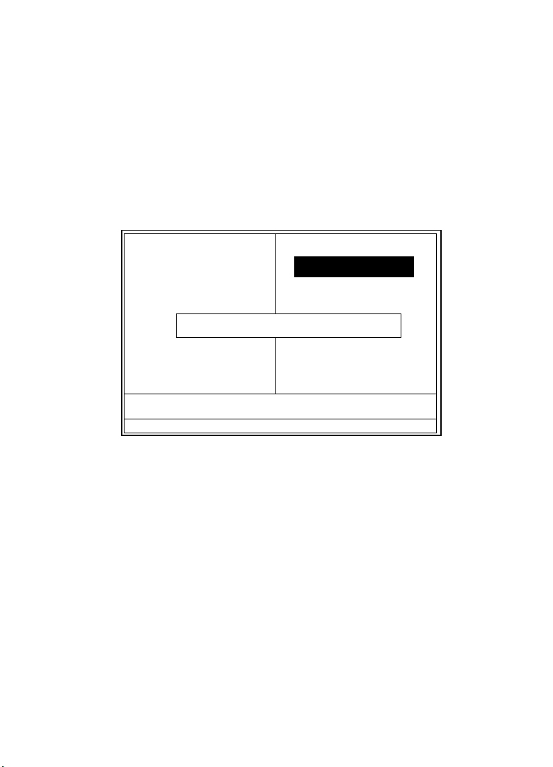
4.10 Load Fail-Safe Defaults
When you press <Enter> on this item,you get a
confirmation dialog box with a message similar to:
◎◎
◎ Figure 10. Load Fail-Safe Defaults
◎◎
CMOS Setup Utility-Copyright(C) 1984-2000 Award
Software
Standard CMOS Features Frequency/Voltage Control
Advanced BIOS Features Load Fail-Safe Defaults
Advanced Chipset Features Load Optimized Defaults
Integrated Peripherals Set Supervisor Password
Power Management Setup Set User Password
PNP/PCI Configuration Save & Exit Setup
PC Health Status Exit Without Saving
Esc : Quit F9 : Menu in BIOS ←→↑↓: Select Item
F10 : Save & Exit Setup
Pressing ‘Y’ loads the default values that are factory settings
for optimal performance system operations.
Load Fail-Safe Default (Y/N)? N
Time , Date , Hard Disk Type ...
Chapter 4 Award BIOS Setup / 63
Page 66
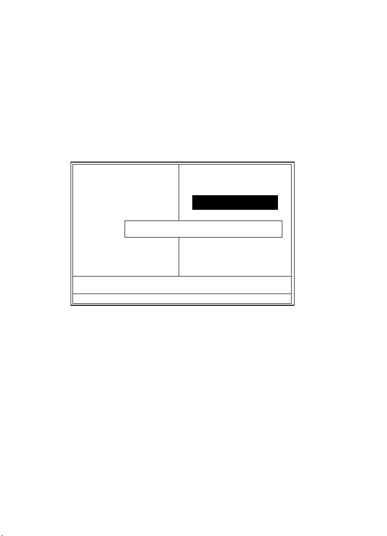
4.11 Load Optimized Defaults
When you press <Enter> on this item,you get a
confirmation dialog box with a message similar to:
◎◎
◎ Figure 11. Load Optimized Defaults
◎◎
CMOS Setup Utility-Copyright(C) 1984-2000 Award
Software
Standard CMOS Features Frequency/Voltage Control
Advanced BIOS Features Load Fail-Safe Defaults
Advanced Chipset Features Load Optimized Defaults
Integrated Peripherals Set Supervisor Password
Power Management Setup Set User Password
PNP/PCI Configuration Save & Exit Setup
PC Health Status Exit Without Saving
Esc : Quit F9 : Menu in BIOS ←→↑↓: Select Item
F10 : Save & Exit Setup
Pressing ‘Y’ loads the default values that are factory settings
for optimal performance system operations.
Load Optimized Default (Y/N)? N
Time , Date , Hard Disk Type ...
64 / Chapter 4 Award BIOS Setup
Page 67
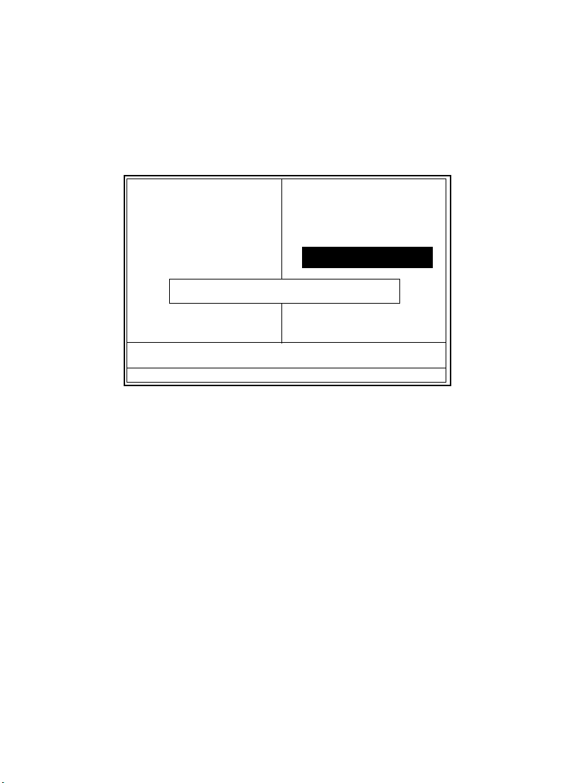
4.12 Set Supervisor / User Password
◎◎
◎ Figure 12. Set Supervisor / User Password
◎◎
CMOS Setup Utility-Copyright(C) 1984-2000 Award
Software
Standard CMOS Features Frequency/Voltage Control
Advanced BIOS Features Load Fail-Safe Defaults
Advanced Chipset Features Load Optimized Defaults
Integrated Peripherals Set Supervisor Password
Power Management Setup Set User Password
PNP/PCI Configuration Save & Exit Setup
PC Health Status Exit Without Saving
Esc : Quit F9 : Menu in BIOS ←→↑↓: Select Item
F10 : Save & Exit Setup
When you select this function, the following message will
appear at the center of the screen to assist you in creating a
password.
Type the password,up to eight characters,and press <Enter>.
The password you type now will clear any previously entered
password from CMOS memory. You will be asked to comfirm
the password. Type the password again and press <Enter>.
You may also press <ESC> to about the selection and not
enter a password.To disable password, just press <Enter>
when you are prompted to enter password. A message will
comfirm that you wish to disable the password. Once the
password is disabled, the system will boot and you can enter
setup freely.
Enter Password:
Time , Date , Hard Disk Type ...
Enter Password
Chapter 4 Award BIOS Setup / 65
Page 68

Password Disabled
If you select “System” at the Security Option of BIOS
Features Setup Menu, you willbe prompted for the password
every time when the system is rebooted, or any time when
you try to enter Setup. If you select “Setup” at Security
Option of BIOS Features Setup Menu, you willbe prompted
only when you try to enter Setup.
66 / Chapter 4 Award BIOS Setup
Page 69
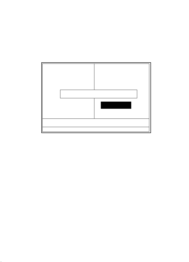
4.13 Save & Exit Setup
◎◎
◎ Figure 13. Save & Exit Setup
◎◎
CMOS Setup Utility-Copyright(C) 1984-2000 Award
Software
Standard CMOS Features Frequency/Voltage Control
Advanced BIOS Features Load Fail-Safe Defaults
Advanced Chipset Features Load Optimized Defaults
Integrated Peripherals Set Supervisor Password
Power Management Setup Set User Password
PNP/PCI Configuration Save & Exit Setup
PC Health Status Exit Without Saving
Esc : Quit F9 : Menu in BIOS ←→↑↓: Select Item
F10 : Save & Exit Setup
Type “Y” will quit the Setup Unility and save the user setup
value to RTC CMOS RAM.
Type “N” will return Setup Unility.
Save & Exit Setup (Y/N)? Y
Time , Date , Hard Disk Type ...
Chapter 4 Award BIOS Setup / 67
Page 70
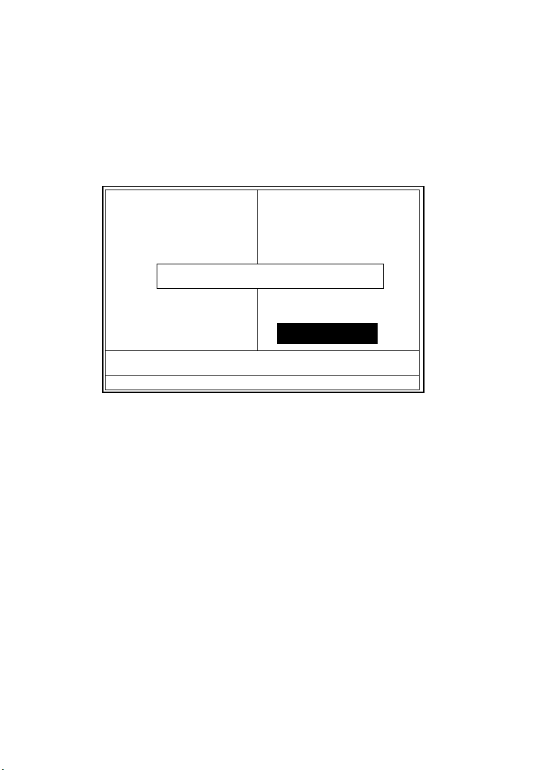
4.14 Exit Without Saving
◎◎
◎ Figure 14. Exit Without Saving
◎◎
CMOS Setup Utility-Copyright(C) 1984-2000 Award
Software
Standard CMOS Features Frequency/Voltage Control
Advanced BIOS Features Load Fail-Safe Defaults
Advanced Chipset Features Load Optimized Defaults
Integrated Peripherals Set Supervisor Password
Power Management Setup Set User Password
PNP/PCI Configuration Save & Exit Setup
PC Health Status Exit Without Saving
Esc : Quit F9 : Menu in BIOS ←→↑↓: Select Item
F10 : Save & Exit Setup
Type “Y” will quit the Setup Unility without saving to RTC
CMOS RAM.
Type “N” will return Setup Unility.
Exit Without Saving (Y/N)? Y
Time , Date , Hard Disk Type ...
68 / Chapter 4 Award BIOS Setup
Page 71

Date : / /
Warranty Card/Technical Fault Report
M/B Model No.: Vender
Serial No. :
Date of Purchasing:
Hardware Configuration Used :
CPU
RAM (Brand,MB)
Video Card
Hard Drive
Other Card
Diagnostic Software Used :
Fault Description :
Chapter 4 Award BIOS Setup / 69
 Loading...