

Page 1

USER’S MANUAL
VERSION 0.8
03 January, 2010
for
CK3-1 CLOCK & THERMOMETER BOARD
Lucid Technologies
http://www.lucidtechnologies.info/
Email: [email protected]
Copyright (C) 2009 by Lucid Technologies
All rights reserved
The information in this manual has been carefully checked and is believed to be accurate.
However, Lucid Technologies makes no warranty for the use of its products and assumes no
responsibility for any errors which may appear in this document. Lucid Technologies reserves the
right to make changes in the products contained in this manual in order to improve design or
performance and to supply the best possible product. Lucid Technologies assumes no liability
arising out of the application or use of any product or circuit described herein; neither does it
convey any license under its patent rights, nor the rights of others.
(C) Lucid Technologies 1
Page 2

CK3 Alarm Clock and Thermometer
1.0 Introduction
2.0 Circuit Description
3.0 Software Description
4.0 Operation
5.0 Circuit Board Construction
6.0 Installation
7.0 Customization
Appendix A CK3 Parts List
Appendix B CK3 Board Layout
Appendix C Chassis Parts List
Appendix D Chassis Details
CONTENTS
Appendix E RS-232 Serial Interface Connector
Appendix F RS-232 Communications Setup
Appendix G MIDI Current-loop Interface Connector
Appendix H References
Appendix I Schematics
(C) Lucid Technologies 2
Page 3

CK3 Alarm Clock and Thermometer
1.0 Introduction
The CK3 is a multi-function circuit board providing a real-time clock, thermometer, RS-232
serial port, and MIDI style current-loop output. The CK3 is designed to interface with a DB1
clock-display via Serial Peripheral Interface (SPI). The CK3 also uses SPI to communicate with the
real-time clock chip and input shift registers. The thermometer chip uses a 1-wire communication
interface. Through changes in software, and hardware options, it is possible to implement almost
any timing function imaginable.
2.0 Circuit Description
2.1 Power Supply
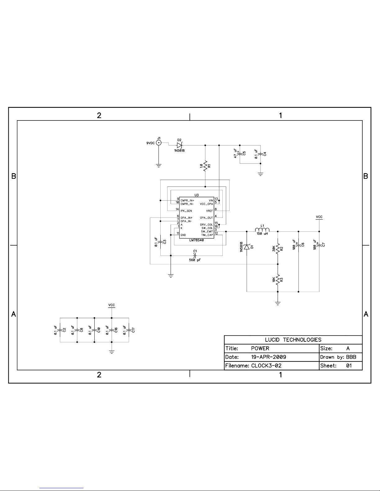
Schematic sheet 1 (Appendix I) shows the power supply circuitry. D2 isolates the 9VDC
wall transformer from the CK3. All the alarm clock circuitry runs on +5V, which is provided by
U3, a 78S40 universal switching regulator subsystem. It is the core of a high efficiency step-down
regulator capable of accepting a wide range of input voltages. The regulator is designed to deliver
+5V at up to 100 mA of current. Under normal operating conditions the alarm clock draws between
30 and 50 mA, depending on the number of active segments in the display. Ground and +5V test
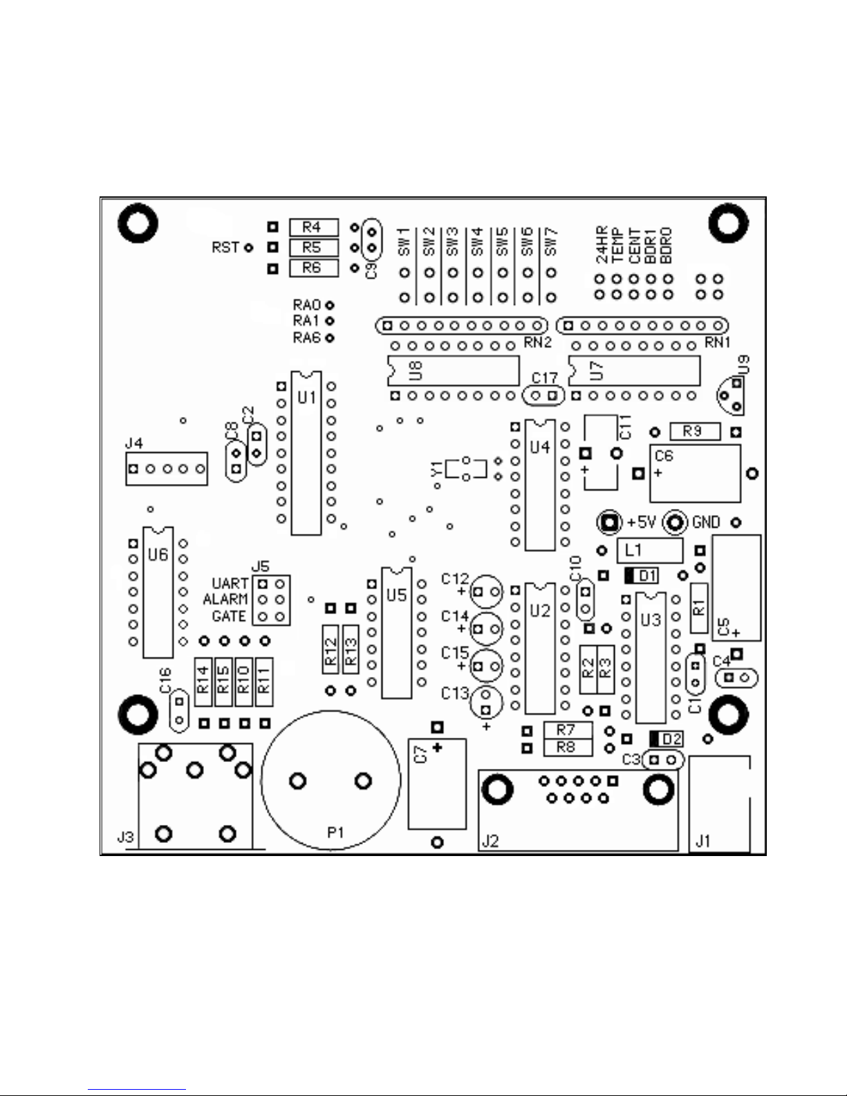
points are provided on the CK3 - see Appendix B.
Bypass capacitors (0.1 uFd) are located near integrated circuits around the board.
2.2 Microcontroller and RS-232 Serial Port
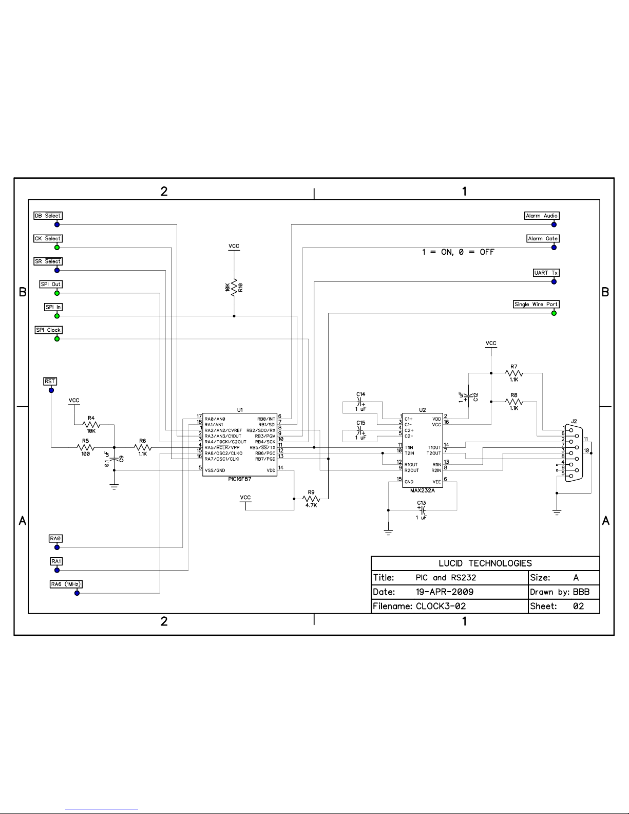
The PIC16F87 microcontroller, or PIC for short, is designated as U1 on sheet 2 of the
schematics. The PIC has 4096 words of flash program memory, 368 bytes of data memory (RAM),
256 bytes of EEPROM memory, a 16-bit timer with prescaler (TMR1), an internal clock oscillator,
a universal asynchronous receiver transmitter (UART), and 16 multi-functional input/output (I/O)
lines. Lucid Technologies standard software for the CK3 sets the internal oscillator to 4 MHz. The
PIC operates at one-fourth of the oscillator frequency or 1 MHz. The 1 MHz operating frequency is
provided at the RA6 test point - see Appendix B. TMR1 overflow interrupts provide a 7.629 Hz
clock used for non-time-keeping delays.
The RS-232 serial port connector (J2) is described in detail in Appendix E. U2 is a
MAX232A, 5V-powered RS-232 interface with two drivers and two receivers. One receiver/driver
pair handles RS-232 data to/from the CK3. The other receiver/driver pair receives RTS and sends it
back to the host as CTS. RTS is also routed to the RB6 input on the PIC. Standard
communications baud rates can be selected with jumpers BDR0 and BDR1. See Appendix F for
details of serial communications setup.
2.3 Real Time Clock and Thermometer
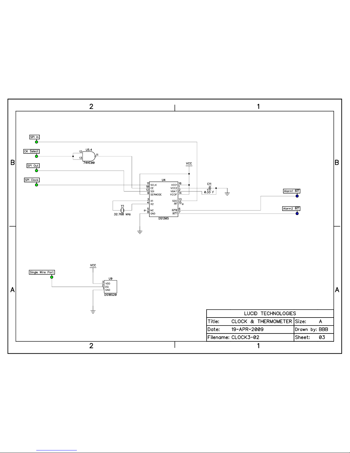
The real time clock (RTC) circuit is shown on sheet 3 of the schematics. The DS1305 chip is
a self contained RTC running off a 32.768 watch crystal. The DS1305 implements a full calendar from seconds to years, has dual alarms, a Serial Peripheral Interface (SPI), and 96 bytes of user
RAM. The DS1305 has two open drain outputs, one for each alarm, that go low at alarm time and
are reset by software.
The DS1305 also has a power backup feature that may be implemented with a battery or
super-capacitor; the CK3 uses a super-capacitor (C11). The super-capacitor takes about an hour to
charge, and once charged it can keep the clock and user RAM powered for eight days. The use of
(C) Lucid Technologies 3
Page 4

CK3 Alarm Clock and Thermometer
the super-capacitor power backup is a big improvement over the battery backup used on the CK2.
As batteries age they can lose capacity, resulting in short backup times, or leak, resulting in circuit
board damage. Use of a super-capacitor solves both of these problems.
The DS18S20 thermometer chip is a 3-lead TO-92 package. It communicates with the PIC
via a bidirectional “1-wire” interface. The DS18S20 is accurate from -10 to 85 degrees Celsius but
most of the other chips on the CK3 are rated for the standard commercial temperature range of 0 to
70 degrees Celsius (32 to 158 degrees Fahrenheit). The software limits the temperature readout to
the commercial range.
2.4 Alarm Circuitry and Current-loop
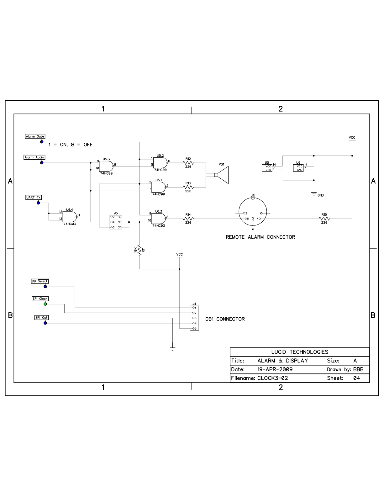
The alarm and current-loop circuitry are shown on sheet 4 of the schematics.
Alarm audio is produced by the piezoelectric speaker, PS1. The terminals of the speaker are
driven by U5.1 and U5.2 respectively. The Alarm_Audio signal from the PIC is inverted by U5.3 so
that the terminals of the speaker are driven in opposition. This increases the volume compared to
the CK2 where only one speaker terminal was driven against ground. If desired, speaker volume
can be reduced by increasing R12 and R13. On the CK2 board, digital noise on the supply could be
heard in a quiet room even when the alarm was off. The CK3 eliminates this with the Alarm_Gate
signal from the PIC. When Alarm_Gate is logic-0 both terminals of the speaker are driven to logic1, thus there is no differential voltage across the speaker to be heard as noise. Lucid Technologies
standard software for the CK3 turns on the Alarm_Gate whenever the alarm is sounding.
The current-loop connector (J3) is configured as a MIDI-OUT connection (Appendix G).
The signal routed to J3 is determined by the jumper on header J5. One, and only one, of the three
positions on J5 should have a jumper. The current-loop is also controlled by the Alarm_Gate signal
from the PIC. When Alarm_Gate is off (logic-0) no current flows, when Alarm_Gate is on (logic-1)
current will flow according to the signal selected on J5. When J5 is in the GATE position, current
flows when Alarm_Gate is on. This can be used to activate a remote alarm such as a shaker for the
blind, or a light for the deaf. When J5 is in the AUDIO position, the current flow replicates the
Alarm_Audio signal. The optically isolated audio signal can be amplified to sound a remote alarm.
When J5 is in the MIDI position, the current flow replicates the PIC UART transmit. If the PIC
baud rate is set to 31250 baud then valid MIDI messages can be sent. Lucid Technologies standard
software for the CK3 does not implement MIDI messages.
2.5 Shift Register Inputs
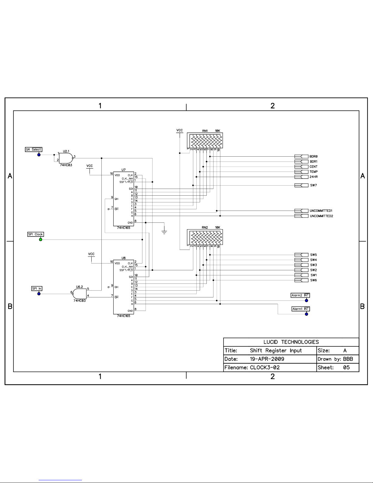
To implement dual alarms the CK3 needs to read seven switches. It also needs to read five
option jumpers and two alarm interrupts. To do this two 74HC165 8-bit parallel-input/serial-output
shift registers were configured as a 16-bit SPI input port. Schematic sheet 5 shows the circuit.
Parallel load of the shift registers happens when the SR_Select signal goes high. Data is clocked out
of the daisy-chained shift registers by the SPI_Clock signal. The inverted output is used because the
shift register data is inverted again by the open-drain output gate, U6.3. An open-drain output is
required because SPI_In is a wire-OR’ed signal.
3.0 Software Description
3.1 Assembler source code
(C) Lucid Technologies 4
Page 5

CK3 Alarm Clock and Thermometer
The assembly language source code for the standard CK3 alarm clock is included on the
disk that came with your kit. The source code is well commented and highly modular. If you know
PIC assembly language it should be easy to understand. If you want to learn more about PIC
programming and the free Microchip Assembler (MPASM) consult some of the excellent resources
on the Microchip web site (see Appendix H for the URL).
The source code begins with several blocks of comments and equates. The comments, lines
that begin with a semicolon, are explanatory text that don’t generate any assembly code. Equates
associate understandable names with fixed numeric values. For example the decimal value 103 is
used to set the UART to 2400 baud, this value is given a more understandable name via the equate:
BD2400 equ D'103'.
The first block, PIC16F87 HARDWARE SETUP, has definitions of the PIC’s I/O pins,
memory addresses, and equates for baud rate settings. The second block, DB1 DISPLAY DATA,
defines the usage of the digits and annunciators on the DB1, and has equates for specific displays.
The third block defines the control and data registers in the DS1305 Real-Time-Clock. The fourth
block defines the PIC I/O pin for the 1-wire interface with the DS18S20 high precision
thermometer. The fifth block is equates for ASCII characters.
The next three blocks are assembler directives, variable definitions and macro definitions.
See the MPASM documentation if you are unfamiliar with any of these concepts.
3.2 Interrupts
The next part of the source code is the interrupt service routine. Only one interrupt is active
in the standard CK3 software, that is the Timer 1 (TMR1) overflow interrupt. The TMR1 prescaler
clocks the 16-bit counter at 500 kHz which produces an overflow interrupt every 131 milliseconds
(7.629 Hz). The interrupt service routine clears the interrupt flag and increments the Timer 1
overflow counter (tmr1ofc) variable.
3.3 Subroutines
The subroutines come next in the source code. The subroutines are well documented and
should be easy to follow for anyone who is familiar with PIC assembly language. The subroutines
are divided into five groups.
1) General Subroutines, such as data conversion; hex to ascii, binary to BCD, delays, etc.
2) UART Subroutines, such as setting baud rates, transmitting and receiving bytes, etc.
3) Synchronous Serial Port Subroutines exchange data with the display, real-time-clock, and
shift register inputs via the SPI.
4) One-wire Bus Subroutines communicate with the DS18S20 thermometer chip. These
routines come from Dallas Semiconductor AN2420 with very little change.
5) Alarm Clock Subroutines to set clock and alarm times, format time data for display, and
generate alarm tones.
3.4 Main Program
The power on reset initialization code begins at the MAIN label. The internal oscillator is
set to 4 MHz, the direction of the I/O ports is set, the TMR1 overflow interrupt is set to 7.629 Hz,
the DB1 display controller and RTC chip are initialized, then the TMR1 overflow interrupt is
enabled.
The label LOOP is the top of the main program loop. The program reads RB6 to see if RTS
(C) Lucid Technologies 5
Page 6

CK3 Alarm Clock and Thermometer
is ON, which means a computer is connected to the RS-232 serial port (J2). If RTS is ON then
program control jumps to label HOST_COM. Host communications is discussed in the next section.
The program then reads and stores all 16 bits from the input shift registers, which includes the
TEMP bit. If TEMP bit is zero then program control goes to TEMP_MODE, otherwise it goes to
CLOCK_MODE.
In TEMP_MODE the program first calls the temperature read routine which reads the
Celsius temperature from the DS18S20, converts it to Fahrenheit, and stores both values in RAM. If
there is no response from the DS18S20 the display will show the message “Err1". This could
happen if a DS18S20 is not installed or is installed backwards. Next the program checks the CENT
(Centigrade or Celsius) bit from the previous read of the input shift registers. If CENT bit is zero
then the Celsius temperature is displayed, otherwise the Fahrenheit temperature is displayed. The
program then delays for approximately 9 seconds then jumps back to LOOP.
In CLOCK_MODE the program checks the A1ENB (Alarm1 Enabled) bit from the previous
read of the input shift registers. If Alarm1 is disabled the program clears the flags for the Alarm1
LED and the Alarm1 audio, then program control jumps to check Alarm2. If Alarm1 is enabled the
program set the flag for the Alarm1 LED and tests the Alarm1 interrupt bit from the previous read
of the input shift registers. If the Alarm1 interrupt is active the program sets the Alarm1 audio flag,
resets the Alarm1 interrupt on the DS1305, then adds 30 to the current minute count and stores the
sum in variable A1end. The program then follows the same process for Alarm2. Next the program
checks the Alarm1 set bit (A1set), from the previous read of the input shift registers, and if active
branches to the set Alarm1 subroutine. The program then checks the Alarm2 set and Time set bits.
The program then reads the current time from the DS1305 and displays. If the Alarm1 audio flag is
set and A1end time has not been reached the program calls the Alarm1 audio routine then jumps to
LOOP. If Alarm1 is inactive the program then checks Alarm2 in the same way. The alarm audio
routines produces about one second of audio before control jumps to LOOP. The time between calls
of the active alarm audio routine is about 160 microseconds so there is no audible interruption of
the sound.
3.5 Serial host communications
When the CK3 is connected via J2 to host computer running a terminal program setup as
shown in Appendix F, the clock display will blank and the following menu should appear in the
host computer’s terminal window.
Lucid Technologies - Clock3
Firmware B.03
1 Set alarm 1
2 Set alarm 2
3 Set clock
4 Display time
5 Display temperature
6 Display settings
7 Exit
?
Menu options are selected by typing the corresponding single number. In the following examples
(C) Lucid Technologies 6
Page 7

CK3 Alarm Clock and Thermometer
the text sent by the CK3 is in italics, the text entered by the user is regular bold. Here is how one
would set Alarm1 to 0645 (6:45 AM). Note that numeric entries require two digits.
?1
Hour(00-23) = 06
Minutes(00-59) = 45
Remember that the DS1305 keeps a full calendar. This example sets the clock to 1730 and zero
seconds on Thursday the 22nd of January, 2009. Because the day, month and year are not needed for
simple alarm clock operations they can only be set via serial host communications.
?3
Year(00-99) = 09
Month(01-12) = 01
Day of month(01-31) = 22
Day of week(01=Monday) = 04
Hour(00-23) = 17
Minutes(00-59) = 30
Option 4 allows one to check the current time.
?4
Time = 17:30:07
Day of week(01=Monday) = 04
Day of month(01-31) = 22
Month(01-12) = 01
Year(00-99) = 09
Option 5 will display the temperature in Celsius and Fahrenheit.
?5
Temperature = 22C = 072F
Option 6 will display the alarms and the state of jumper options.
?6
Alarm1 = 06:45:00
Alarm2 = 19:05:00
Time display selected
24 hour display selected
Fahrenheit display selected
2400 baud
Option 7 is selected to terminate host communications. The normal clock display will return after
the RS-232 cable is disconnected.
4.0 Operation
(C) Lucid Technologies 7
Page 8
CK3 Alarm Clock and Thermometer
4.1 Option jumpers
The CK3 has five option jumpers located at the upper right corner of the circuit board as
shown in Appendix B. When the 24HR jumper is open the CK3 defaults to 12 hour format, when it
is shorted all times are displayed in 24 hour format.
When the TEMP jumper is open the CK3 defaults to clock mode, when it is shorted the CK3
is in thermometer mode. In thermometer mode the CENT jumper determines how temperatures are
displayed. With the CENT jumper open temperature is shown on the Fahrenheit scale, with the
jumper shorted temperature is shown on the Celsius scale. The thermometer chip is rated from 0 to
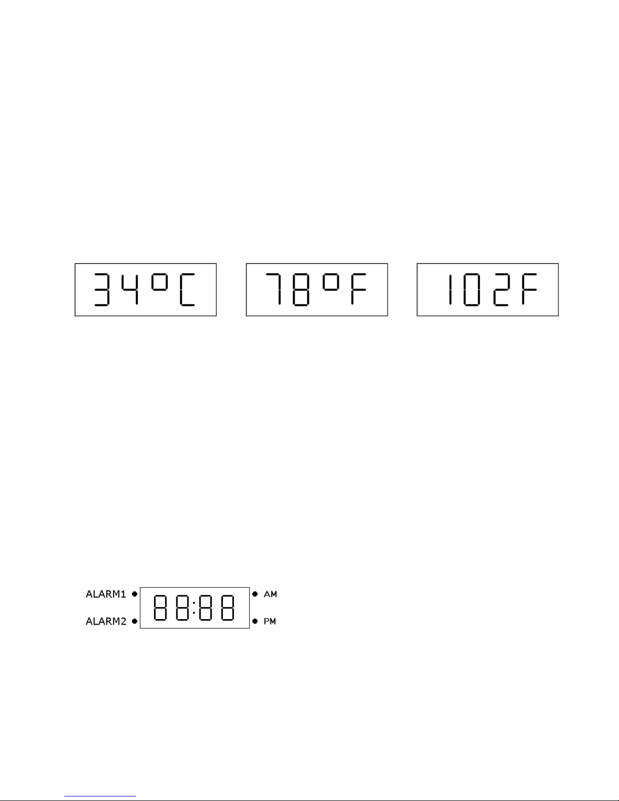
70 degrees Celsius, 32 to 158 degrees Fahrenheit, so the temperature display has to handle both 2
and 3 digit temperature displays, this is shown in Figure 3.1.
Figure 4.1 Display formats for Celsius, two digit, and three digit Fahrenheit.
The BRD0 and BRD1 jumpers set the baud rate, see Appendix F for details.
4.2 Setting times
There are three times that can be set - time of day, Alarm1 time, and Alarm2 time.
Assuming normally-open pushbuttons are used for the set switches, to set any of the times press and
hold the set pushbutton for that time. While the set pushbutton is held, press either the minute set or
hour set pushbutton. Hold the second pushbutton down until the minutes or hours increment to the
correct value. If you miss the correct value just keep the button depressed and the minutes or hours
will wrap around. When setting times the minutes and hours are independent so the hour will not
increment when the minutes go from 59 to 00.
During normal operation the colon, between the hours and minutes digits, blinks every other
second. When any time set switch is active the colon will be on continuously.
4.3 Display annunciators
There are four discrete annunciator
LEDs on the display board; their function is
shown here in Figure 4.2. The LEDs to the
right of the time display are the AM and PM
indicators; AM is the upper indicator and PM
is the lower. The AM and PM indicators are
Figure 4.2 Annunciator LED definitions.
not used for the 24 hour display format. The
alarm indicators are on continuously whenever
their respective alarm is enabled. The alarm indicators blink whenever their respective alarm is
being set.
(C) Lucid Technologies 8
Page 9

CK3 Alarm Clock and Thermometer
4.3 Power backup
The DS1305 RTC has a super-capacitor power backup (C11). The super-capacitor takes
about an hour to charge, and once charged it can keep the clock and user RAM powered for eight
days. This is more than enough to keep the time accurate through typical power interruptions. The
DS1305 is the only chip with backup power, but it is the chip that keeps the time and the alarms,
not the microcontroller. Alarms that trigger during a power outage will not sound until the power
returns.
4.4 Alarms
Each alarm has a distinctive sound so you can tell which alarm is sounding just by hearing
them. Alarm1 alternates between two tones: high, low, high, low, etc. Alarm2 is a rapidly
descending series of eight tones that repeats every second.
When a alarm occurs the tone will sound for 30 minutes or until the enable switch is toggled
off. If the sounding of the alarms overlaps Alarm1 will take precedence.
5.0 Circuit Board Construction
5.1 Preparation
You will need the following tools:
> A low wattage soldering pencil, approximately 10 to 20 Watts.
> Flux core solder wire, organic flux core preferred.
> Lead benders.
> Lead/wire clippers.
Before beginning assemble, carefully check the CK3 circuit board for shorted or incomplete
traces and confirm all parts against the list in Appendix A.
5.2 Assembly checklist
Check the value/type of each part as you assemble the board. Clip excess lead length from
each component after it's soldered. See Appendix B for parts placement.
Insert and solder the low-profile sockets for:
____ U1 18-pin DIP.
____ U2 16-pin DIP.
____ U3 16-pin DIP.
____ U4 16-pin DIP.
____ U5 14-pin DIP.
____ U6 14-pin DIP.
____ U7 16-pin DIP.
____ U8 16-pin DIP.
Insert and solder the following components.
____ R1 1.0 ohm, 0.25W, 5% (brown-black-gold-gold)
(C) Lucid Technologies 9
Page 10

CK3 Alarm Clock and Thermometer
____ R2 30K, 0.25W, 5% (orange-black-orange-gold)
____ R3 10K, 0.25W, 5% (brown-black-orange-gold)
____ R4 10K, 0.25W, 5% (brown-black-orange-gold)
____ R5 100 ohm, 0.25W, 5% (brown-black-brown-gold)
____ R6 1.1K, 0.25W, 5% (brown-brown-red-gold)
____ R7 1.1K, 0.25W, 5% (brown-brown-red-gold)
____ R8 1.1K, 0.25W, 5% (brown-brown-red-gold)
____ R9 4.7K, 0.25W, 5% (yellow-violet-red-gold)
____ R10 10K, 0.25W, 5% (brown-black-orange-gold)
____ R11 10K, 0.25W, 5% (brown-black-orange-gold)
____ R12 220 ohm, 0.25W, 5% (red-red-brown-gold)
____ R13 220 ohm, 0.25W, 5% (red-red-brown-gold)
____ R14 220 ohm, 0.25W, 5% (red-red-brown-gold)
____ R15 220 ohm, 0.25W, 5% (red-red-brown-gold)
____ RN1 10k, 10-pin SIP, pin 1 goes in the square pad.
____ RN2 10k, 10-pin SIP, pin 1 goes in the square pad.
____ D1 1N5818, banded end toward square pad.
____ D2 1N5818, banded end toward square pad.
____ C1 560 pFd, radial
____ C2 0.1 uFd, radial
____ C3 0.1 uFd, radial
____ C4 0.1 uFd, radial
____ C5 47 uFd, positive lead toward square pad.
____ C6 100 uFd, positive lead toward square pad.
____ C7 100 uFd, positive lead toward square pad.
____ C8 0.1 uFd, radial
____ C9 0.1 uFd, radial
____ C10 0.1 uFd, radial
____ C11 0.33F, 5.5V, radial
____ C12 1.0uF, radial
____ C13 1.0uF, radial
____ C14 1.0uF, radial
____ C15 1.0uF, radial
____ C16 0.1 uFd, radial
____ C17 0.1 uFd, radial
____ Y1 bend leads to center crystal between hold-down pad.
____ Secure Y1 with a clipped lead wire over the crystal can.
____ L1 150uH inductor
____ P1 piezoelectric speaker
____ U9 DS18S20 in TO-92 package
____ J1 DC power jack
____ J2 DB9 female
____ J3 DIN-5 receptacle
____ J5 3x2 jumper header
(C) Lucid Technologies 10
Page 11
CK3 Alarm Clock and Thermometer
____ 5x2 option header
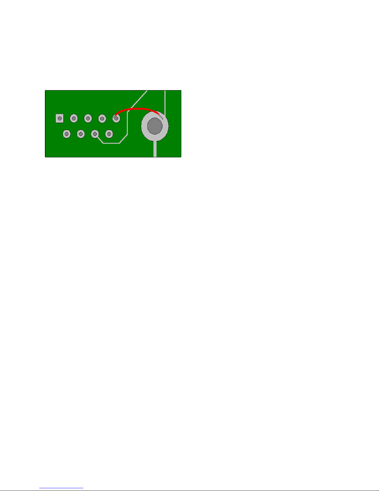
The CK3-1 printed circuit board has one small omission. Pin 5 on connector J2 was not grounded.
On the bottom side of the board solder a short
insulated wire between J2 pin 5 and the grounded
mounting pad for J2 as shown in Figure 5.1
The display board (DB1) can now be connected.
Figure 5.1
This can be done with discrete wires soldered on
the CK3 and DB1 ends, or by wires soldered to
CK3 (J4) with a connector on the other end that mates with a header on DB1 (J1). In either case,
the wires should be at least 3.5" (9cm) long. Pin 1 on both boards is the square pad.
____ CK3, J4(1) to DB1, J1(1)
____ CK3, J4(2) to DB1, J1(2)
____ CK3, J4(3) to DB1, J1(3)
____ CK3, J4(4) to DB1, J1(4)
____ CK3, J4(5) to DB1, J1(5)
5.3 Circuit Board Checkout
You will need a multimeter or oscilloscope to check out the CK3 circuitry. Place the CK3
circuit board on an insulating surface. DO NOT install the integrated circuits yet.
Attach the negative lead of your voltmeter to the ground test point. Plug-in the 9V wall
transformer and connect it to J1 on the CK3. The supply voltage should measure at least 8VDC on
the positive lead of C5 (47 uFd). Disconnect the wall transformer at J1 then insert the 78S40 in
socket U3. Reconnect the wall transformer then measure the voltage at the +5V test point. The
voltage should be between 4.9 and 5.1 volts.
If there is a problem, disconnect the wall transformer and inspect the CK3. Be sure the
78S40 is not backwards in the socket. Check that diodes D1, D2 and capacitors C4, C5 are not
installed backwards. Refer to schematic page 1 and check the value of all other resistors and
capacitors attached to U3. Correct any errors and check +5V again.
Disconnect the wall transformer again, then insert the remainder of the integrated circuits. If
it isn’t already hardwired to the CK3 connect the DB1. Reconnect the wall transformer. The display
should come up showing midnight (12:00 AM) and one minute later it should change to 12:01 AM.
If this happens we know the PIC, DB1, 74HC00 and DS1305 are all functioning. Put a jumper on
the 24HR option header; the display should change to 0001 and the AM LED should go off. If this
happens we know the shift registers and 74HC03 are also functioning. Connect a RS-232 cable
from your host computer to J2. If you should see the menu described in section 3.5 you know the
PIC and MAX232 are functioning.
If the board is not functioning you will need to locate the problem. The CK3 circuit board
design has been proven reliable so the most likely faults are solder bridges, components installed
(C) Lucid Technologies 11
Page 12

CK3 Alarm Clock and Thermometer
backwards, or components soldered in the wrong place.
If there is no display on the DB1 you can check the power and control lines going to the
display. With the power off measure the resistance between the GND test point and ground on the
DB1, J1(3). The resistance should of course be almost zero. With the power on check for +5 volts
on DB1, J1(5). Using an oscilloscope or logic probe look at DB1, J1(1), this is the display select
line which should pulse low about once a second. Next look at DB1, J1(2); this is the synchronous
data clock to all SPI peripherals which should be low the majority of the time with frequent series
of high pulses. Finally, check DB1, J1(4); serial data to the display board and clock chip. The
serial data should exhibit a series of pulses. If these pins are functioning normally we can be
confident the PIC is good, and any problem is with the DB1. If the PIC is the problem, be sure it is
not installed backwards in the socket.
Use the schematics to check for various faults. If the PIC oscillator isn’t functioning then no
program instructions are being executed. The oscillator is functioning normally if test point RA6 is
approximately a 1 MHz square wave. The pad labeled RST on the CK3 is an input that can be used
to reset the PIC. Grounding the RST pad will reset the PIC.
6.0 Installation
Take a look at Section 7 (Customization) before wiring your switches. Depending on how
you want to use the CK3 you may need more or less switches than you might imagine.
6.1 Prepare the Case
Begin by identifying the bottom half of the case. The two screw that hold the case together
go through the bottom half of the case. The posts that these screws pass through are toward the rear
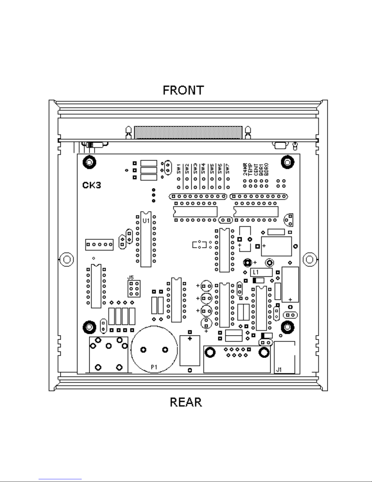
of the case, as shown in Figure D1. There are four short posts for mounting the CK3 board inside
the case.
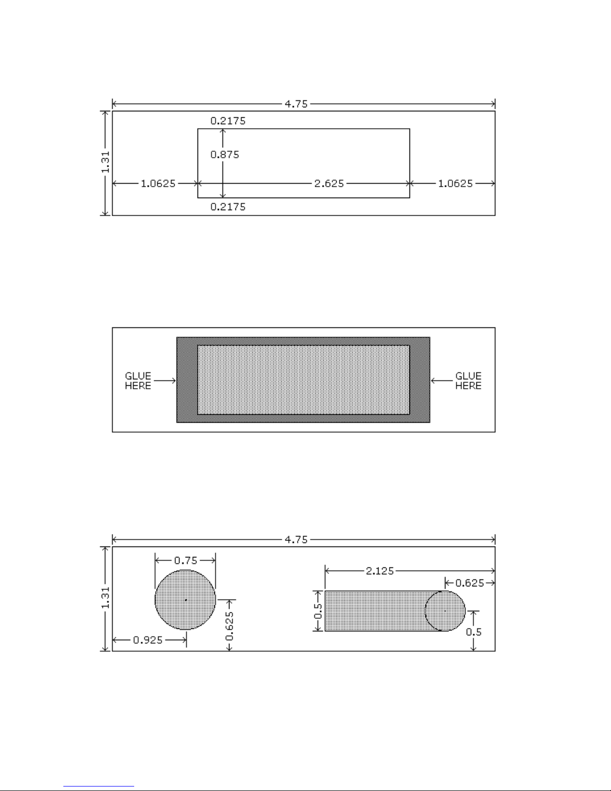
The next step is to add the red window to the front panel. Make a rectangular cutout two
and five-eighths (2.625) by seven-eighths (0.875) inches centered in the front panel, see Figure D2.
Smooth the edges of the cutout and remove any plastic burrs. Place the front panel face down on a
work surface. Position the red plexiglass window on top of the panel, centered on the cutout, see
Figure D3. Place a drop of super-glue at the left and right edges of the window, the glue should
seep between the window and front panel. This will bond the red plexiglass window to the inside of
the front panel. Don’t pick up the front panel until the glue has dried.
Holes must be drilled in the rear panel for the power plug (J1) and the current-loop
connector (J3). The hole for J1 can be used to start the cutout for the DB-9 connector (J2). Figure
D4 shows the position of the holes and cuts.
Now we can start working on the top half of the case. First we’ll drill the holes for the
switches. There is no specific location for switches, you can put them wherever is best for you, but
pay attention to two things. First, identify the front and rear of the top half, if you drill the holes in
the wrong place you can’t just turn it around, the case only fits together one way! Second, watch
the vertical clearance between the bottom of your switches and parts on the CK3 circuit board. See
Appendix C for suggested switches. Temporarily place the CK3 and DB1 in the bottom half of the
case so you can measure clearances. After marking the switches’ locations on the top, drill the
required size mounting holes for the switches you are using. Securely mount the switches in the top
(C) Lucid Technologies 12
Page 13

CK3 Alarm Clock and Thermometer
half of the case.
2.6 Switches
The switches must now be wired to the CK3 circuit board. Remove the 74HC165 chips (U7
and U8) and store them in a safe place while soldering to the CK3. Schematic sheet 5 shows the
switch inputs to the CK3. One side of each switch is grounded and this ground can be daisychained around the switches, reducing the total number of wires going to the CK3. The row of pads
closest to the labels (SW1-SW7) are the ground pads, the row closest to RN2 are the signal pads.
Allow enough slack in the wires so that the case can be opened to change option jumpers.
Lucid Technologies standard software for the CK3 expects all the switches to be normallyopen, in other words, the input is active when the signal line is grounded. The software also assigns
the following functions to the switch inputs.
Switch Function
SW1 Alarm1 set (A1set)
SW2 Alarm1 enable (A1enb)
SW3 Alarm2 set (A2set)
SW4 Alarm2 enable (A2enb)
SW5 Hours set (Hrset)
SW6 Minutes set (MNset)
SW7 Time set (Tmset)
The alarm_set and alarm_enable switches may be combined into one switch in the form of a
center-off toggle.
6.2 Final Checkout
Put the 74HC165s back in their sockets. Connect the DB1 as it was for the functional
checks. Plug-in the wall transformer and attach it to CK3, J1. Try setting the time-of-day and
alarm-time. If none of the switches work you may have inserted a 74HC165 upside down. Check
that the alarm LEDs blink when setting the alarm-time and are on continuously when the alarm is
enabled. If switches don’t perform the anticipated function you may have wired them to the wrong
SWX pad on the CK3. Correct any errors and check again.
6.3 Final Assembly
The last construction step is to clean the board. If you used organic core solder just rinse the
board in warm water. If you used acid core solder try scrubbing it with an old toothbrush and
rubbing alcohol.
Attach the CK3 circuit board to the bottom half of the case using the four self-tapping
screws that came with the kit. Insert the front panel into the most forward slot such that the red
plexiglass window is on the inside. Insert the DB1 circuit board into the slot behind the front panel.
Insert the rear panel into the rear slot so that the hole lines up with the connectors. Place the top on
the case being sure not to pinch any wires in the seam. Use the long self-tapping screws that came
with the case to securely close the case. Attach the wall transformer to the clock via the hole in the
(C) Lucid Technologies 13
Page 14

CK3 Alarm Clock and Thermometer
rear panel.
7.0 Customization
The CK3 offers lots of opportunities for customization to meet your needs. Here are a few
of the ideas we have cataloged. If you come up with your own hardware or software ideas please
let us know and we will post them on the web for other CK3 owners.
7.1 Hardware customization
! If you only need one alarm there is no need to install switches for the second alarm. The
standard software will always see the second alarm’s inputs as inactive.
! Alarm volume can be adjusted by changing the value of R12 and R13. R12 and R13 should
be of equal value and not less than 100 ohms. Increasing their value decreases the alarm
volume; decreasing their value increases the alarm volume.
! The TEMP jumper determines whether the CK3 functions as a clock or a thermometer. It
was made an internal jumper with the idea that the CK3 would be setup as either a clock or a
thermometer. Wires can be run from the TEMP jumper to a SPST toggle switch allowing
external selection of the clock or thermometer mode.
! The 24HR jumper determines whether the time is displayed in 12 or 24 hour format. It was
made an internal jumper with the idea that the user would always want the same format.
Wires can be run from the 24HR jumper to a SPST toggle switch allowing external selection
of the time display format.
! The CENT jumper determines whether the temperature is displayed in Fahrenheit or
Centigrade format. It was made an internal jumper with the idea that the user would always
want the same format. Wires can be run from the CENT jumper to a SPST toggle switch
allowing external selection of the temperature display format.
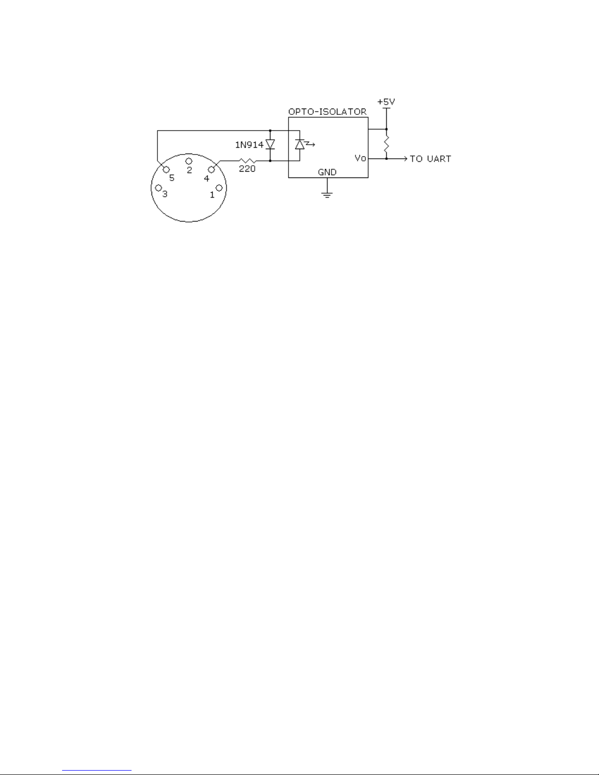
! With the J5 jumper in the ALARM position the alarm audio signal is routed to the current-
loop output on J3. A optically-isolated (see Figure G2) remote audio amplifier can be
connected to J3.
! With the J5 jumper in the GATE position the alarm gate signal is routed to the current-loop
output on J3. The alarm gate signal is on over 99% of the time while the alarm is sounding -
it goes off just a few microseconds every second. A optically-isolated low-pass-filter can be
used to control a remote audio alarm, or a light, or a bedframe vibrator.
! Time-of-day and alarm-times can be set via the RS-232 connection. If all you need is a
clock without alarms, and are willing to set the time via RS-232, then the case doesn’t need
any switches. If you do need an alarm, but the alarm-time never, or seldom changes, then
you need just an alarm enable switch.
7.2 Software Customization
You will need two things to customize the CK3 software. The first is a PIC assembler Lucid Technologies recommends the MPLAB Integrated Development Environment (MPLAB IDE)
which can be downloaded for free from the Microchip Technology website. The second is a
programmer compatible with the PIC16F87.
(C) Lucid Technologies 14
Page 15

CK3 Alarm Clock and Thermometer
! You can make your own unique alarm tones by writing new alarm sound generation
routines. See the subroutines Alarm1 and Alarm2 as examples.
! With the J5 jumper in the UART position the PIC’s UART output is routed to the current-
loop output on J3. The software could be modified to send MIDI commands instead of
generating a local audio alarm. Imagine waking up to music from your synthesizer!
! With the ability to communicate via RS-232 and current-loop, the CK3 can send messages
whenever the software tells it. Remote alarm, time and temperature indicators could be
controlled from the CK3. Remote temperature recording could also be done.
! There are two uncommitted inputs, configured as jumpers connected to shift register U7,
located at the upper right of the circuit board (see Appendix B). These inputs can be used
for any function you can program.
! There are two uncommitted I/O lines, RA0 and RA1, locate just above U1 on the circuit
board (see Appendix B). These connect directly to the PIC and can be used for any function
you can program.
! The software can be modified to dim the display at night. See the DB1 manual and
MC14489 data sheet for details
! The standard software functions as a time-of-day alarm clock, but with the thermometer chip
available it could function as a temperature alarm system. Imagine sounding alarms, or
sending RS-232 messages, when the temperature get too high or too low!
! The DS1305 is a full clock and calendar system. How about special alarms, or messages, on
your birthday or anniversary?
! Does your custom software have data it needs to store that could be lost during a power
outage? The PIC has 256 bytes of EEPROM, and the DS1305 has 96 bytes of user RAM
protected by its super-capacitor power backup.
(C) Lucid Technologies 15
Page 16

CK3 Alarm Clock and Thermometer
APPENDIX A
CK3 PARTS LIST
Quantity Part Reference
===============================================================
1 560pF, 35V, radial C1
8 0.1uF, 35V, radial C2,C3,C4,C8,C9,C10,C16,C17
1 47uF, 35V, axial C5
2 100uF, 25V, axial C6,C7
1 0.33F, 5.5V, radial C11
4 1.0uF, 50V, radial C12,C13,C14,C15
1 1.0 ohm, 0.25W, 5% R1 (brown-black-gold-gold)
1 30K, 0.25W, 5% R2 (orange-black-orange-gold)
4 10K, 0.25W, 5% R3,R4,R10,R11 (brown-black-orange-gold)
1 100 ohm, 0.25W, 5% R5 (brown-black-brown-gold)
3 1.1K, 0.25W, 5% R6,R7,R8 (brown-brown-red-gold)
1 4.7K, 0.25W, 5% R9 (yellow-violet-red-gold)
4 220 ohm, 0.25W, 5% R12,R13,R14,R15 (red-red-brown-gold)
2 10K, 10-SIP, pin-1 common RN1,RN2
2 1N5818, 30V D1,D2
1 PIC16F87-I/P, 18-DIP U1
1 MAX232CPE, 16-DIP U2
1 78S40, 16-DIP U3
1 DS1305, 16-DIP U4
1 74HC00, 14-DIP U5
1 74HC03, 14-DIP U6
2 74HC165, 16-DIP U7,U8
1 DS18S20, TO-92 U9
1 18-DIP socket U1
5 16-DIP socket U2,U3,U4,U7,U8
2 14-DIP socket U5,U6
1 DC power jack J1
1 DB9 female J2
1 DIN-5 receptacle J3
1 3x2 jumper header J5
1 5x2 option header
1 150uH L1
1 Piezo speaker P1
1 32768Hz tuning fork crystal Y1
1 CK3-1 circuit board
1 Jumper
(C) Lucid Technologies 16
Page 17
CK3 Alarm Clock and Thermometer
APPENDIX B
CK3 BOARD LAYOUT
(C) Lucid Technologies 17
Page 18

CK3 Alarm Clock and Thermometer
APPENDIX C
CHASSIS PARTS LIST
The chassis parts list includes all parts not located on the circuit boards. Some suggested
sources and part numbers are given. Where equivalent parts are known, multiple part numbers are
shown. Other equivalent parts may be available from other sources.
Plastic case, 1 required
PacTec www.pactecenclosures.com 1-610-361-4200
Model CM5-125
Simco www.simcobox.com 1-800-780-9090
Model 150X5, Challenger series
Time Set switches, 3 required
Radio Shack 275-1571, Submini momentary pushbutton, SPST
(Time Set, Hours Set, and Minutes Set)
Alarm switches (one per alarm)
Radio Shack 275-325, Center-off mini toggle switch, SPDT
(Alarm Set and Alarm Enable)
Wall transformer
Voltage output: 9VDC
Current output: 100 mA or more
Output connector: coaxial power plug, 5.5mm O.D., 2.1mm I.D., center positive
Screws 4 required for mounting printed circuit board
(C) Lucid Technologies 18
Page 19
CK3 Alarm Clock and Thermometer
APPENDIX D
CHASSIS DETAILS
Figure D1. Position of the CK3 circuit board and DB1 circuit board in the bottom half of the
alarm clock case.
(C) Lucid Technologies 19
Page 20
CK3 Alarm Clock and Thermometer
Figure D2. Window cutout in the case’s front panel insert. Figure shows dimensions in inches:
2.625" = 67mm, 1.0625" = 27mm, 0.875" = 22mm, 0.2175" = 5.5mm.
Figure D3. Position of the red plexiglass window glued to the inside of the front panel.
APPENDIX E
Figure D4. Rear view of the case’s rear panel insert. Figure shows dimensions in inches: 0.925"
= 23.5mm, 0.75" = 19mm, 0.625" = 16mm, 0.5" = 12.7mm.
(C) Lucid Technologies 20
Page 21

CK3 Alarm Clock and Thermometer
RS-232 SERIAL INTERFACE CONNECTOR
The table below shows the most commonly implemented signals and their pin assignments
in accordance with RS-232D. Host computers are usually DTE (Data Terminal Equipment) and
modems are DCE (Data Communications Equipment). Note that circuits are named from the point
of view of the DTE. For example, circuit BB (receive data) is actually data transmitted by the DCE.
DCE devices originally used a 25 pin, female, D connector.
Pin Circuit Description Direction
1 AA Protective ground, PG n/a
2 BA Transmit data, TD to DCE
3 BB Receive data, RD from DCE
4 CA Request to send, RTS to DCE
5 CB Clear to send, CTS from DCE
6 CC Data set ready, DSR from DCE
7 AB Signal ground, SG n/a
8 CF Data carrier detect, DCD from DCE
20 CD Data Terminal ready, DTR to DCE
22 CE Ring indicator, RI from DCE
In recent years all personal computer have migrated to the use of a 9 pin, male, D connector instead
of the 25 pin connector. The pin assignments for such a DTE device are shown below.
Pin Circuit Description Direction
1 CF Data carrier detect, DCD from DCE
2 BB Receive data, RD from DCE
3 BA Transmit data, TD to DCE
4 CD Data Terminal ready, DTR to DCE
5 AB Signal ground, SG n/a
6 CC Data set ready, DSR from DCE
7 CA Request to send, RTS to DCE
8 CB Clear to send, CTS from DCE
9 CE Ring indicator, RI from DCE
All Lucid Technologies products are designed as DCE devices. They use a 9 pin, female, D
connector that is directly compatible with 9 pin COM ports found on personal computers. The pin
(C) Lucid Technologies 21
Page 22

CK3 Alarm Clock and Thermometer
assignments for this connector are shown below.
Pin Circuit Description Direction
1 CF Data carrier detect, DCD from CK3
2 BB Receive data, RD from CK3
3 BA Transmit data, TD to CK3
4 CD Data Terminal ready, DTR to CK3
5 AB Signal ground, SG n/a
6 CC Data set ready, DSR from CK3
7 CA Request to send, RTS to CK3
8 CB Clear to send, CTS from CK3
9 CE Ring indicator, RI from CK3
None of the handshake lines are actively controlled by the CK3. DTR is not connected and
thus is ignored. DSR and DCD are hard-wired to the ON condition (ON = spacing = +voltage) at
all times. RTS is received, buffered, and looped back to the host as CTS; thus CTS tracks RTS.
(C) Lucid Technologies 22
Page 23

CK3 Alarm Clock and Thermometer
APPENDIX F
SERIAL COMMUNICATIONS SETUP
The CK3 can talk to a host computer via a serial COM (RS-232) port. Newer PCs may not
posses a COM port but communication is still possible via a USB-to-Serial-Adapter (such as the
IOGEAR GUC232A). Baud rates are selected via the BDR0 and BDR1 jumpers on the option
header - they are located at the upper right corner of the circuit board as shown in Appendix B.
BDR1 BDR0 Baud Rate
Open Open 2400
Open Shorted 4800
Shorted Open 9600
Shorted Shorted 19200
The PC must run a terminal emulation program to communicate with the CK3. Several
freeware terminal emulation programs are available. We will use HyperTerminal here as an
example because it came bundled with all versions of Microsoft Windows prior to Vista. If you're
using Vista you can download Hyperterminal for free here: http://www.hilgraeve.com/htpe/. For
older versions of Windows, if HyperTerminal wasn't part of your original installation you can add it
now by going to the Control_Panel and double-clicking on Add/Remove_Programs. Select the
Windows_Setup tab, then under Components, click the Communications line and the Details
button. Be sure HyperTerminal is selected and click OK. When the Add/Remove_Programs
window returns click OK. For Windows XP HyperTerminal can be found at: Start / All Programs /
Accessories / Communications. When you first start HyperTerminal a Connection_Description
window will come up. Enter a name, such as “CK3 alarm clock", and select an icon, then click OK.
A Connect_To window will come up. Go to the Connect_Using line and select the COM-port you
will use to connect to the CK3; then click OK. Remember, this is a direct connection, you are not
going through a modem. A COMX_Properties window will come up next. Make the following
settings:
Select the baud rate (Bits per second) to use with the CK3.
Data bits = 8
Parity = None
Stop bits = 1
Flow control = None, then click OK.
Now click on the File menu, Properties, and select the Settings tab. Set Emulation to ANSI. Click
on the ASCII_Setup button. Set the Line_delay to 1 millisecond and the Character_delay to 0
milliseconds. Click the OK button for the ASCII_setup window and the OK button on the
Properties window.
The last step in the setup is to save the terminal settings so you won't have to go through this
(C) Lucid Technologies 23
Page 24

CK3 Alarm Clock and Thermometer
process every time you use HyperTerminal. Click on the File menu, Save_as, check that the file
name is correct, (for example CK3.ht) and click on Save. The next time you want to run
HyperTerminal you can simply double-click on the file name (CK3.ht) and HyperTerminal will
begin with all the correct settings.
Connect your CK3 to the COM-port and turn it on; the initial menu should appear
in the HyperTerminal window.
(C) Lucid Technologies 24
Page 25
CK3 Alarm Clock and Thermometer
APPENDIX G
MIDI CURRENT-LOOP INTERFACE CONNECTOR
MIDI, or the Musical Instrument Digital Interface, is an industry-standard protocol defined
in 1983 that enables electronic musical instruments, computers, and other equipment to
communicate, control, and synchronize with each other. MIDI allows computers, synthesizers,
MIDI controllers, sound cards, samplers and drum machines to control one another, and to
exchange system data.
MIDI does not transmit an audio signal, it transmits "event messages" such as the pitch and
intensity of musical notes to play, control signals for parameters such as volume, vibrato and
panning, cues, and clock signals to set the tempo. As an electronic protocol, it is notable for its
widespread adoption throughout the industry.
MIDI compatible devices have DIN 5/180! female connectors. MIDI cables use DIN 5/180!
male connectors. There are three types of MIDI ports found on MIDI compatible instruments:
MIDI-IN, MIDI-OUT, and MIDI-THRU. The difference between the MIDI-OUT and MIDI-THRU
ports is that data coming from the MIDI-OUT port has been generated on the device containing that
port. Data that comes out of a device's MIDI-THRU port, however, is an exact duplicate of the data
received at the MIDI-IN port. One output (MIDI-OUT or MIDI-THRU) may drive one and only
one input (MIDI-IN).
The electrical MIDI interface is an optically isolated current-loop. Logic zero is current
ON. Data is sent in standard asynchronous serial format at 31.25 kilobaud with 8 data bits, no
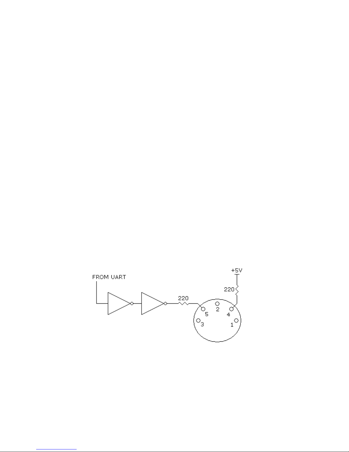
parity, and one stop bit. The transmit circuitry of a MIDI output connector is shown in Figure G1.
The optically isolated receive circuitry of a MIDI-IN connector is shown in Figure G2.
.
Figure G1 Standard MIDI-OUT or MIDI-THRU output
circuitry.
(C) Lucid Technologies 25
Page 26
CK3 Alarm Clock and Thermometer
Figure G2 Standard MIDI-IN input circuitry.
The MIDI current-loop connector on the CK3 board (J3) is a MIDI-OUT connector. With
the J5 jumper in the UART position the UART’s TX output is routed to both the RS-232 connector
(J2) and the MIDI-OUT connector (J3). To send MIDI data the software must be changed to set the
PIC16F87's UART to 31250 baud.
(C) Lucid Technologies 26
Page 27

CK3 Alarm Clock and Thermometer
APPENDIX H
REFERENCES
Maxim (www.maxim-ic.com)
Data Sheet - DS1305, Serial Alarm Real-Time Clock, REV: 070705
Data Sheet - DS18S20, High-Precision 1-Wire Digital Thermometer, REV: 042208
Application Note 162, Interfacing the DS18X20/DS1822 1-Wire Temperature Sensor in a MicroController Environment
Application Note 506, Interfacing SPI Real-Time Clocks (RTC) with Microcontroller
Application Note 2361, Interfacing an SPI-Interface RTC with a PIC Microcontroller
Application Note 2420, 1-Wire Communication with a PICmicro Microcontroller
Application Note 3517, Estimating Super Capacitor Backup Time on Trickle-Charger Real-Time
Clocks
Application Note 3816, Selecting a Backup Source for Real-Time Clocks
Microchip (www.microchip.com)
PIC16F87/88 Data Sheet, DS30487C
AN1199, 1-Wire Communication with PIC Microcontroller, DS01199A
Motorola (Freescale) (www.freescale.com)
Data Sheet - MC14489, Multi-Character LED Display/Lamp Driver
National (www.national.com/analog)
Data Sheet - LM78S40 Universal Switching Regulator Subsystem
On Semiconductor (www.onsemi.com)
Application Note 920 - Theory and applications of the MC34063 and uA78S40 switching regulator
control circuits
(C) Lucid Technologies 27
Page 28

CK3 Alarm Clock and Thermometer
(C) Lucid Technologies 28
Page 29
Page 30
Page 31
Page 32
Page 33
 Loading...