


Optical Amplifier Platform, 1724-Type
Erbium-Doped Fiber Amplifier (W Series)
Applications
■
Designed specifically for DWDM applications
■
Booster/power amplifier
■
Line amplifier
Description
The W1724-Type Erbium-Doped Fiber Amplifier
(EDF A) has been designed for use in DWDM applications and offers the following performance features:
Data Sheet, Rev. 1
September 2001
Designed for use in DWDM applications, the standard
W1724-Type EDFA incorporates a DB-25 connector and a
microcontroller with TTL compatible alarm monitoring.
Features
■
Gain-flattened spectral response
■
High saturation output power, > 22 dBm
■
Low power consumption, < 12 W @ 45 °C
■
Low noise
■
Single 5 V operation
■
Wide input signal bandwidth
■
Wide operating temperature range, 0 °C to 65 °C
■
Optical input and output taps
■
Isolated input and output
■
Programmable input and output monitors
■
Flat gain profile over a wide temperature range
■
Low noise figure
■
High output power
■
Automatic gain lock
The versatile W1724-Type EDFA operates over a
wide temperature range, exhibits extremely low
power dissipation, and offers a variety of alarms and
monitors. Optimum performance and system stability
are supported through the use of optical isolation at
the input and output. Optical input and output are
through single-mode fiber pigtails terminated with
optical connectors.
The EDFA incorporates optical input and output taps
that are monitored via an integral microcontroller.
Significant performance benefits are achieved with
the microcontroller, which stabilizes the temperature
of the pumps and maintains constant gain of the
amplifier.
Contact your Account Manager at Agere Systems
Inc. to discuss electrical or optical connector options
not listed in the Ordering Information section.
■
Connectorized single-mode fiber pigtail
■
Standard serial communication channels

Data Sheet, Rev. 1 Optical Amplifier Platform, 1724-Type
September 2001 Erbium-Doped Fiber Amplifier (W Series)
Standard Features
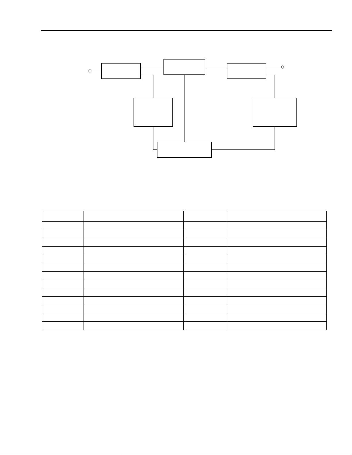
The standard W1724-Type EDFA incorporates the optical architecture illustrated in Figure 1. The standard
features include:
■
Exceptional performance benefits with the integral
microcontroller, which precisely controls the gain to
maintain a flat spectral response over various input
powers.
■
Single 5 V power supply eliminates the need for dual
voltage source circuits.
■
DB-25 electrical connector allows for easy electrical
connectivity.
■
Optical input tap enables input monitoring and control.
■
SC/PC optical connector.
■
Low power dissipation.
■
Alarms:
— Loss of input power alarm.
— Loss of output power alarm.
— Pump bias alarm (>95% of EOL value).
— Pump temperature alarm (T
— EDFA temperature alarm (T
■
Advanced microprocessor design requires minimal
engineering for a shelf-level product.
■
Standard mechanical outline includes metric screws
and fiber outputs (using SC/PC optical connectors)
at 180 degrees relative to a DB25 electrical connector. The standard product does not include a heat
sink.
L
> 35 °C).
C
> 60 °C).
TTL-Compatible Alarm Outputs
Loss of Input Power Alarm
If the input power is more than 2 dBm below the minimum P
activate (TTL-logic 1).
Loss of Output Power Alar m
If the output power decreases by more than 2 dB from
its beginning-of-life value, the loss of output power
alarm (pin 8) will activate (TTL-logic 1).
Pumps Temperature Alarm
If the laser temperature for the pump(s) exceeds 35 °C,
the pump temperature alarm (pin 10) will activate (TTLlogic 1).
Pumps Bias Alarm
If the bias current for the pump(s) exceeds 95% of its
EOL value, the pump bias alarm (pin 9) will activate
(TTL-logic 1).
EDFA Tempera ture Alarm
If the case temperature exceeds 60 °C, then the
EDFA temperature alarm (pin 7) will activate (TTLlogic 1).
, the loss of input power alarm (pin 19) will
IN
Optional Features
Other feature and package options for the W1724-Type
EDFA include:
■
Alternative optical connectors
■
Integral heat sink
2
2
Agere Systems Inc.
Optical Amplifier Platform, 1724-Type Data Sheet, Rev. 1
Erbium-Doped Fiber Amplifier (W Series) September 2001
Block Diagram
OPTICAL
INPUT
SIGNAL
INPUT TAP
Figure 1. W1724-Type EDFA Block Diagram
PD #1
INPUT POWER
MONITOR
MICROCONTROLLER
OPTICAL GAIN
OUTPUT TAP
OUTPUT POWER
MONITOR
OPTICAL
OUTPUT
SIGNAL
PD #2
1-904 (C)
Pin Information
Table 1. Pin Descriptions for a Microcontrolled (Full) Amplifier
Pin Description Pin Description
1 5.0 V (±0.25 V) 14 GND
2 5.0 V (±0.25 V) 15 GND
3 5.0 V (±0.25 V) 16 GND
4 5.0 V (±0.25 V) 17 GND
5 Reserved
6 Reserved
7 EDFA Temperature Alarm 20 Reserved
8 Loss of Output Power Alarm
9 Pumps Bias Alarm
10 Pumps Temperature Alarm
11 EDFA Shutdown Override
12 5.0 V (±0.25 V) 25 GND
13 GND — —
1.Do not connect to reser ved pins.
2.Normal = TTL low, alarm = TTL high if the output power falls 2 dB below the minimum value.
3.Normal = TTL low, alarm = TTL high if pump bias exceeds 95% of its end-of-life value.
4.Normal = TTL low, alarm = TTL high if pump temperature exceeds 35 °C.
5.The EDFA is equipped with an optical transient suppression feature when this pin is tied to GND. The EDFA will turn all pumps off, if the
input power is too low. Tying this pin to 5 V will disable this feature; however, damage to the optical connectors and components may occur if
the amplifier is turned on without the presence of an optical signal.
6. Normal = TTL low, alarm = TTL high if input power is less than 2 dB below minimum P
Amplifier enable (all pumps are on) = TTL low, amplifier disable (all pumps are off) = TTL high.
7.
1
1
2
3
4
5
18 RS-232 OUT (TTL)
19 Loss of Input Power Alarm
1
21 Amplifier Disable Input
7
22 RS-232 IN (TTL)
23 Reserved
1
24 5.0 V (±0.25 V)
IN
.
6
Agere Systems Inc.
3

Data Sheet, Rev. 1 Optical Amplifier Platform, 1724-Type
September 2001 Erbium-Doped Fiber Amplifier (W Series)
Absolute Maximum Ratings
Stresses in excess of the absolute maximum ratings can cause permanent damage to the device. These are absolute stress ratings only. Functional operation of the device is not implied at these or any other conditions in excess
of those given in the operational sections of the data sheet. Exposure to absolute maximum ratings for extended
periods can adversely affect device reliability.
Parameter Symbol Min Typ Max Unit
Storage Temperature T
Operating Case Temperature T
stg
C
Absolute Humidity — — — 0.024 lbs. H
–40 20 70 °C
03565 °C
2
O/lbs. dry air
Electrical Characteristics
Table 2. Power Supply
Parameter Symbol Min Typ
dc Power Supply Voltage V
Power Supply Current
I
PS1
PS1
*
4.75 5.0 5.25 V
—1.0— A
Max Unit
(beginning of life)
Power Supply Current
I
PS1
——1.9A
(end of life)
Electrical Power Consumption
——5.0—W
(beginning of life)
Electrical Power Consumption
———10.0W
(end of life)
* Typical operating characteristics: V
PS1
= 5.0 V, TC = 35 °C.
Table 3. TTL Inputs/Outputs
Under normal operating conditions, the various alarm outputs will be TTL level low. If the corresponding parameter
is outside a predesignated range, the associated alarms will become TTL level high.
Parameter Symbol Min Typ Max Unit
2
—
2.4
0
—
—
—
0.8
V
V
—
0.1
—
0.4
V
V
Input Voltage:
High
Low
Output Voltage:
High
Low
IH
V
IL
V
OH
V
OL
V
Input Current:
High
Low
Output Current:
High
Low
IH
I
IL
I
—
—
—
—
–1
1
OH
I
OL
I
—
—
—
—
–4
20
µA
µA
mA
µA
4
Agere System s Inc.

Optical Amplifier Platform, 1724-Type Data Sheet, Rev. 1
Erbium-Doped Fiber Amplifier (W Series) September 2001
Optical Characteristics
Table 4. Performanc e Specifications for W Series
Parameter Symbol Min T yp Max Unit
Signal Wavelength Range:
W1724CDDAD
W1724CBBAD
W1724CBBAH
Gain Flatness:
W1724CDDAD
W1724CBBAD
W1724CBBAH
Intput Power:
W1724CDDAD
W1724CBBAD
W1724CBBAH
Output Power:
W1724CDDAD
W1724CBBAD
W1724CBBAH
Noise Figure:
W1724CDDAD
W1724CBBAD
W1724CBBAH
Optical Isolation — 25 — — dB
Return Loss RL — — –40 dB
Reverse ASE Power Level P
Polarization-mode Dispersion PMD — — 1.0 ps
Polarization-dependent Gain PDG — — 0.5 dB
λ
L
GF
P
IL
P
OUT
NF
ASE,R
1530
1549.32
1549.32
—
—
—
–17
–20
–28
8
4.5
4.5
—
—
—
—
—
—
1.3
—
—
—
—
—
—
—
—
5.0
—
—
1560
1560.61
1560.61
2.0
1.5
1.5
–8
–8
–16
17
17.8
17.8
6.0
5.5
5.5
nm
nm
nm
dB
dB
dB
dBm
dBm
dBm
dBm
dBm
dBm
dB
dB
dB
——–20dBm
Agere Systems Inc.
5

Data Sheet, Rev. 1 Optical Amplifier Platform, 1724-Type
September 2001 Erbium-Doped Fiber Amplifier (W Series)
Outline Drawings
W1724-Ty pe EDFA Package
Dimensions are in inches and (millimeters).
MOUNTING HOLES
M3 x 0.5, 5 mm DEEP
LABELS AS
REQUIRED
HEATSINK MOUNTING HOLES
M3 x 0.5, 4.5 mm DEEP
4 PLACES
5 PLACES
5.074
(128.88)
5.90
(149.9)
0.41
(10.4)
DANGER
LABEL
4.660
(118.36)
0.12
(3.0)
DB 25
CONNECTOR
MALE
PIN 1
LABEL
6
ESD
0.44
(11.2)
4.90
(124.5)
4.57
(116.08)
0.165
(4.19)
0.83
(21.1)
2.285
(58.04)
0.03
(0.8)
3.795
(96.39)
5.570
(141.48)
INFORMATION LABEL
3.10
(78.7)
0.90
(22.9)
0.76
(19.3)
0.17
(4.2)
1-997(F)
Agere System s Inc.

Optical Amplifier Platform, 1724-Type Data Sheet, Rev. 1
Erbium-Doped Fiber Amplifier (W Series) September 2001
Outline Drawings
(continued)
Optional Package Configuration: W1724-Type EDFA Package with Integral Heat Sink
Dimensions are in inches and (millimeters).
1.500
(38.10)
0.41
(10.5)
5.90
(149.9)
5.074
(128.88)
CUSTOMER
LABEL
DANGER
LASER WARNING
LABEL
0.033
(0.84)
0.44
(11.2)
DB 25
CONNECTOR
(MALE)
0.123
(3.12)
4.660
(118.36)
0.98
(24.8)
AGERE SYSTEMS
Breinigsville, Pennsylvania
USA
DATE MANUFACTURED:
NOVEMBER 1997
3.94
(100.1)
4.91
(124.7)
0.76
(19.3)
MOUNTING HOLES
M3 x 0.5, 5 mm DEEP
AS NOTED BY DIMPLE
4 PLACES
1.850
(46.99)
1.53
(38.9)
0.38
(9.5)
PIN 1
1-998(C)
Agere Systems Inc.
7

Data Sheet, Rev. 1 Optical Amplifier Platform, 1724-Type
September 2001 Erbium-Doped Fiber Amplifier (W Series)
Ordering Information
Table 5. Ordering Information
Device Code Po Connector Heat Sink Comcode
W1724CDDAD 17.0 dBm FC/PC Yes 108358433
W1724CBBAD 17.0 dBm SC/PC No 108338674
W1724CBBAH 17.0 dBm SC/PC No 108396102
* Contact your Account Manager to discuss your requirements. (If you do not know your Account Manager, please call the Optoelectronics unit
at Agere Systems directly at (610) 391-2520.)
*
Related Product Information
Table 6. Related Product Information
Description Part Number Document Number
High-Speed Lightwave Receiver 1319-Type DS97-106LWP
Lithium Niobate Modulator — DS98-110LWP
Electroabsorption Modulated Isolated Laser Module E2500-Type DS98-368L WP
1.5 µm Isolated DFB Laser Module D2500-Type DS98-339L WP
1.3 µm Isolated DFB Laser Module D2300-Type DS97-122LWP
0.98 µm Pump Laser Module 263-Type DS99-199LWP
Long-Wavelength PIN Photodetectors 131-Type DS98-206LWP
Interfacing the 1724-Type Microprocessor-Controlled
Erbium-Doped Fiber Amplifier via a Serial Communication Port
1725-Type Gain Block Erbium-Doped Fiber Amplifier 1725 DS00-271LWP
Optical Amplifier Platform, 1730-Type Erbium-Doped Fiber
Amplifier
Extended Band (L-Band) 1735-Type Gain Block Erbium-Doped
Fiber Amplifier
1724-Type AP99-020LWP
S1730-Type DS99-353LWP
1735-Type DS00-113OPTO
8
Agere System s Inc.

Optical Amplifier Platform, 1724-Type Data Sheet, Rev. 1
g
Erbium-Doped Fiber Amplifier (W Series) September 2001
Laser Safety Information
FDA/CDRH Class IIIb and
®
IEC
60825 Class 3B laser product.
All versions of the product are FDA/CDRH Class IIIb laser products. The product complies with the U.S. Code of
Federal Regulations (CFR), Title 21, Part 1040.10 and 1040.11 laser product regulations.The product is registered/
certified with the FDA under accession number 9320325.
All versions are Class 3B laser products per
IEC
60825-1:1993.
Optical Specifications
Optical fiber: single-mode, 8.8 µm/125 µm (mode field/cladding diameter) pigtail with connector.
Nominal wavelength: 1550 nm.
Absolute maximum output power: <500 mW.
Product is not shipped with power supply.
CAUTION: Use of controls, adjustments, and procedures other than those specified herein may result in
hazardous laser radiation exposure.
DANGER
DANGER
INVISIBLE LASER RADIATION
AVOID DIRECT EXPOSURE TO BEAM
Max. Output: 500 mW,
Wavelen
th: 1.5 µm
Class IIIb La s e r Pro d uct
INVISIBLE LASER RADIATION
IS EMITTED FRO M THE END
OF FIBER OR CONNECTOR
Avoid direct exposure to beam
Do not view beam directly with
optical instruments
LASER APERTURE
INVISIBLE LASER RADIATION EMITTED FROM END OF FIBER OR CONNECTOR
Avoid exposure to beam
Class 3B Laser Product IEC-60825 1993 Max. Output: 500 mW Wavelength: 1.55 µm
Agere Systems Inc.
9

Data Sheet, Rev. 1 Optical Amplifier Platform, 1724-Type
September 2001 Erbium-Doped Fiber Amplifier (W Series)
IEC
is a registered trademark of the International Electrotechnical Commission.
For additional information, contact your Agere Systems Account Ma na ger or the following:
INTERNET:
E-MAIL:
N. AMERICA: Agere Systems Inc., 555 Union Boulevard, Room 30L-15P-BA, Allentown, PA 18109-3286
ASIA: Agere Systems Hong Kong Ltd., Suites 3201 & 3210-12, 32/F, Tower 2, The Gateway, Harbour City, Kowloon
EUROPE:
Agere Systems Inc. reserves the right to make changes to the product(s) or information contained herein without notice. No liability is assumed as a result of their use or application.
Copyright © 2001 Agere Systems Inc.
All Rights Reserved
http://www.agere.com
docmaster@agere.com
1-800-372-2447
Tel. (852) 3129-2000
CHINA:
JAP AN:
Tel. (44) 7000 624624
, FAX 610-712-4106 (In CANADA:
, FAX (852) 3 129-2 020
(86) 21-5047-12 12
(81) 3-5421-160 0
, FAX (44) 1344 488 045
(Shanghai),
(Tokyo), KOREA:
(86) 10-6522-5566
1-800-553-2448
(82) 2-767-1850
, FAX 610-712-4106)
(Beijing),
(86) 755-695-7224
(Seoul), SINGAPORE:
(Shenzhen)
(65) 778-8833
, TAIWAN:
(886) 2-2725-5858
(Taipei)
September 2001
DS00-123OPTO-1 (Replaces DS00-123OPTO)
 Loading...