

Page 1

Quick Installation
Guide
;EZI43-28--%GGIWW4SMRX
011908/A September 1999
Copyright © 1999 Lucent Technologies Inc. All Rights Reserved
You can find the latest software & documentation at:
http://www.wavelan.com/support
Page 2

About this Document
The product described in this book is a licensed product of Lucent
Technologies Inc.
• WaveLAN, WavePOINT and WaveMANAGER are registered trademarks or trademarks of Lucent Technologies Inc.
• Microsoft MS-Windows and MS-DOS are registered trademarks or
trademarks of Microsoft Corporation.
• Novell and NetWare are registered trademarks of Novell, Inc.
• Adobe Acrobat is a registered trademark of Adobe Systems Inc.
All other brand and product names are trademark s or reg ist ered tradem arks o f
their respective holders.
This Document was created by:
Lucent Technologies Nederland B.V.
Wireless Communications & Networking Division (WCND)
P.O. Box 755
3430 AT Nieuwegein
The Netherlands
September 22, 1999
It is the policy of Lucent Technologies to improve products as new
technology, components, software, and firmware become available. Lucent
Technologies, therefore, reserves the right to change specifications without
prior notice.
All features, functions, and operations described herein may not be marketed
by Lucent Technologies in all parts of the world. In some instances, drawings
are of equipment prototypes. Therefore, before using this document, consult
your Lucent Technologies representative or Lucent Technologies office for
information that is applicable and current.
Copyright ©1999 Lucent Technologies Inc., All Rights Reserved
An electronic copy of this document is also available on the enclosed
software CD-ROM. Updates of this document can be downloaded from the
WaveLAN Library on the World Wide Web at
http://www.wavelan.com.
To view or print the electronic document, in Adobe’s Portable Document
Format (PDF), you will need the Adobe Acrobat Reader®, included on the
enclosed Software CD-ROM.
Alternatively, consult the Adobe website at:
http://www.adobe.com.
We value your feedback.
If you find errors or omissions in this book, or if you can suggest ways to
improve its usefulness, we would like to hear from you. Please contact us at:
Telephone: + 31 30 609 7471
Fax: + 31 30 609 763 6
E-Mail: moolen@lucent.com
Sincerely,
William van der Moolen
Page 3

Table of Contents
Table of Contents i
Technical Support v
Regulatory Information vi
1 Welcome 1-1
Introducing WavePOINT-II 1-1
■ About the WavePOINT-II 1-1
Finding Information 1-5
■ The Quick I nstallation Guide 1-5
■ The WaveMANAGER User’s Guide 1-6
■ The On-line Help Information 1-6
■ Conventions Used in This Document 1-7
Kit Contents 1-8
Selecting the Right WaveLAN Card 1-9
■ WaveLAN IEEE Adapters 1-9
■ Bronze, Silver & Gold Labels 1-12
■ Can I Use Different Card Types Together? 1-13
■ WaveLAN Legacy Adapters 1-14
■ WaveLAN IEEE versus Legacy WaveLAN 1-15
Optionally Available Products 1-17
2 Installing the WavePOINT-II 2-1
Introduction 2-1
■ WavePOINT-II Placement 2-1
■ Indoor Antenna Placement 2-2
■ Outdoor Antenna Placement 2-3
WavePOINT-II - Quick Installation Guide i
Page 4

Table of Contents
Table of Contents
Hardware Installation 2-4
■ Verifying Kit Contents 2-4
■ Registering your WaveLAN Products 2-4
■ Placing Mounting Plate and Power Supply 2-6
■ Mounting the Processor Module 2-7
■ Connecting the Network Interfaces 2-8
■ Mounting the WavePOINT-II Cover Plate 2-10
Powering-up WavePOINT-II 2-12
3 Beyond Quick-Start... 3-1
Introduction 3-1
■ Connect Stations to your WavePOINT-II 3-1
■ Configure your WavePOINT-II 3-3
A WavePOINT-II Specifications A-1
Hardware A-1
Software A-2
B WavePOINT-II Start-up Configuration B-1
Identify the Start-up Settings B-1
C Additional Installation Instructions C-1
WaveLAN Legacy Radio Modules C-1
■ Mounting the WaveLAN/PCMCIA Radio C-2
■ Mounting the WaveLAN/EAM Radio C-3
ii WavePOINT-II - Quick Installation Guide
Page 5

Table of Contents
Removing the Cover Plate C-7
W Warranty Repair Card W-1
About Warranty and Repair W-1
Limite d Warranty W-2
List of Figures LOF-1
List of Tables LOT-1
Index IX-1
WavePOINT-II - Quick Installation Guide iii
Page 6

Page 7

Technical Support
You can find the most recent software and user documentation for
all WaveLAN products on our internet site.
Software and Documentation
World Wide Web http://www.wavelan.com
FTP Server ftp://ftp.wavelan.com/pub
If you encounter problems when installing or using this product, or
would like information about our other WaveLAN products, please
contact your local Authorized WaveLAN Reseller, or regional
Lucent Technologies Sales Office. You can find their address
and phone numbers on the WaveLAN website.
In case no local or regional support is available, you can reach us
at the addresses or telephone numbers listed below.
WaveLAN Regional Support
U.S.A / Canada usasupport@wave lan .co m
Caribbean/ Latin America calasupport@wavelan.com
Europe/ Middle-East/ Africa emeasupport@wavelan.com
Asia/ Pacific apasupport@wavelan.com
WaveLAN Global Support
U.S.A / Canada Voice: +1 800 WAVELAN-3
Caribbean/ Latin America
When contacting WaveLAN Support, please complete the
WaveLAN Problem Report form and include it with your email.
The form (report.txt) is available on the WaveLAN Software CDROM, and on the WaveLAN Support pages of the WaveLAN
website.
WavePOINT-II - Quick Installation Guide v
Page 8

Regulatory Information
Lucent Technologies is not responsible for any radio or television interference caused by
unauthorized modification of this device or the substitution or attachment of connecting cables
and equipment other than specified by Lucent Technologies. The correction of interference
caused by such unauthorized modification, substitution or attachment will be the responsibility
of the user.
The devi ce de s cri b ed in t h is do cu me nt ca n be u s ed i n co mb i na ti on wi t h o th e r wi r e les s p rod uc t s
and/or antennas. Whenever applicable the user shall always consult the documentation that
came with such devices for additional Regulatory Information and/or Safety and Installation
Requirements that might apply to the wireless installation.
USA - Federal Communications Commission (FCC) 0
This equipment has been tested and found to comply with the limits for Class B Digital Devices,
pursuant to Part 15 of the FCC Rules. These limits are designed to provide reasonable
protection against harmful interference in a residential installation. This equipment generates,
uses and can radiate radio frequency energy and, if not installed and used in accordance with
the instruction, may cause harmful interference to radio communications. However, there is no
guarantee that interference will not occur in a particular installation. If this equipment does
cause harmful interference to radio or television reception, which can be determined by turning
the equipment off and on, the user is encouraged to try to correct the interference by one or
more of the following measures:
• Reorient or relocate the receiving antenna.
• Increase the separation between the equipment and the receiver.
• Connect the equipment into an outlet on a circuit different from that to which the
receiver is connected.
• Consult the dealer or an experienced radio/TV technician for help.
Canada - Industry Canada (IC) 0
This class B digital apparatus meets all requirements of the Canadian Interference Causing
Equipme nt Regulations.
Cet appareil numéric de la class B respecte toutes les exigences du Règlement sur le matériel
brouilleur du Canada.
EU Declaration of Conformity 0
Lucent Technologies declares, that the WavePOINT-II conforms to the specifications listed
below, following the provisions of the Low Voltage Directive 73/23/EEC and the EMC Directive
89/336/EEC:
Safety EN60950/IEC950
EMC EN55022/CISPR22 Class B
EN61000-3-2/EN61000-3-3
EN50082-1
vi WavePOINT-II - Quick Installation Guide vi
Page 9

Welcome
1
Introducing WavePOINT-II 1
Welcome to WaveLAN, the easy way to wireless computing.
Building your own wireless network has never been easier.
This book introduces you to WavePOINT-II, and will help you to get
your network “on the air” within a snap. It describes the most
common configurations and a quick start set-up.
To install and manage WaveLAN products, it is assumed that you
have a working knowledge of installation procedures for network
operating systems under Microsoft Windows 95 and Windows NT.
About the WavePOINT-II 1
The WavePOINT-II bridge is a modular unit with an integrated
Ethernet interface and two PC Card slots, that enable you to use
your WavePOINT-II with:
■ WaveLAN IEEE 802.11 PC Cards.
■ WaveLAN Legacy adapter cards.
The dual slot design allows you to configure the WavePOINT-II to
operate with almost any combination of the wired and wireless
network interfaces listed above. This way your WavePOINT-II
device provides easy migration paths between various generations
of WaveLAN products.
WavePOINT-II - Quick Installation Guide 1-1
Page 10
Welcome
Introducing WavePOINT-II
The WavePOINT-II is a transparent Media Access Control (MAC)
bridge that exists in two versions:
■ WavePOINT-II Access Point.
■ WaveACCESS LINK WP-II.
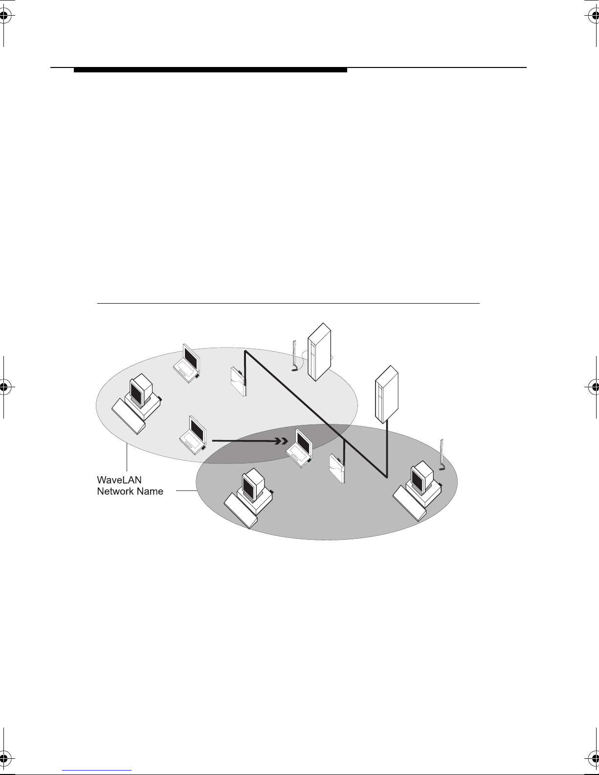
WavePOINT-II Access Point 1
The Access Point is a wired to wireless bridge that you can use to
connect wireless cells to one another or to a wired (Ethernet) Local
Area Network. The Access Point can serve mobile wireless clients
roaming between various locations within a network premises.
Figure 1-1 WavePOINT-II Access Point
1-2 WavePOINT-II - Quick Installation Guide
Page 11
Welcome
Introducing WavePOINT-II
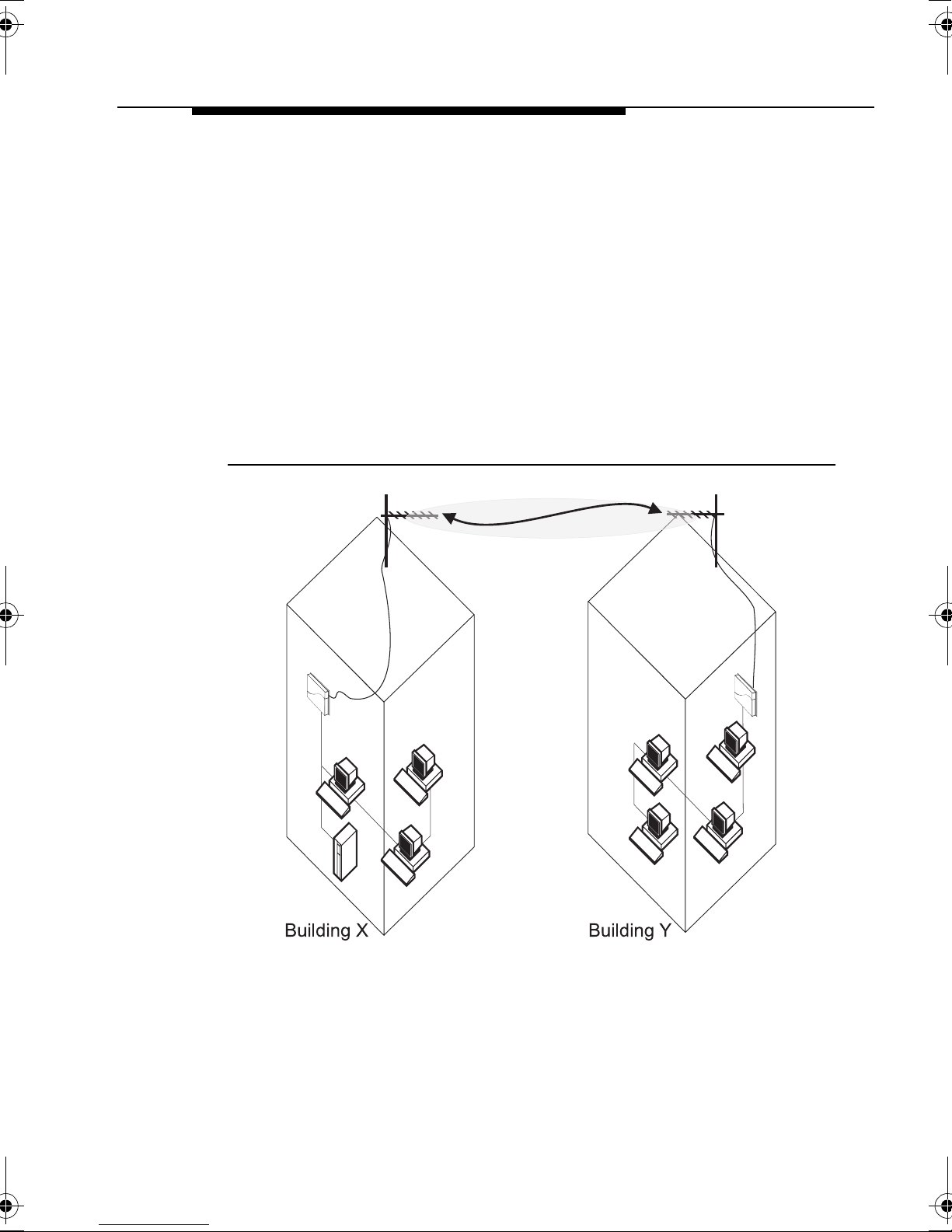
WaveACCESS LINK WP-II 1
The WaveACCESS LINK WP-II bridge, previously known as the
WavePOINT-II Point-to-Point (PTP) bridge, has been designed to
serve a wireless backbone between wireless cells and/or wireless
(outdo or) antenna link.
The WaveACCESS LINK WP-II device is based on the same
hardware design as the WavePOINT-II Access Point. Besides its
wireless point-to-point bridging functionality, the WaveACCESS
LINK WP-II also supports the access point features as described
on the previous page.
Figure 1-2 WaveACCESS LINK WP-II
WavePOINT-II - Quick Installation Guide 1-3
Page 12

Welcome
Introducing WavePOINT-II
When you wish to use the WaveACCESS LINK WP-II in an
outdoor antenna installation, you are advised to consult the
information described in the “WaveLAN Outdoor Antenna
Installation Guide, which can be downloaded from the document
Library on the WaveLAN website at:
http://www.wavelan.com
NOTE:
To install a WavePOINT-II device, you will need at least
one WaveLAN interface card. This card is not included
with your WavePOINT-II Kit, but must be ordered as an
additional item. For more information about the various
card types available please refer to the section “Selecting
the Right WaveLAN Card” on page 1-9.
1-4 WavePOINT-II - Quick Installation Guide
Page 13

Welcome
Finding Information
Finding Information 1
WavePOINT-II, together with WaveLAN network adapter cards,
enables you to build a variety of network configurations:
■ A wireless LAN environment for mobile computers.
■ A flexible network, that allows for adding and/or relocating
workstations quickly and easily.
■ A migration path between various generation WaveLAN
infrastructures.
■ An inexpensive alternative to leased lines for building-to-
building links (WaveACCESS LINK WP-II only).
To design and install your wireless network, you can find the
information you need in the following information products:
■ The Quick Installation Guide
■ The WaveMANAGER User’s Guide
■ The On-line Help Information
The Quick Instal lation Guide 1
The Quick Installation Guide ( this document) describes:
■ The contents of your WavePOINT-II Kit (see page 1-8).
■ How to install the WavePOINT-II hardware (see Chapter 2).
■ How to power up the device using the default factory-set
settings (see Chapter 3).
■ The hardware specifications of your WavePOINT-II device
(see Appendix A).
WavePOINT-II - Quick Installation Guide 1-5
Page 14

Welcome
Finding Information
The W ave MANAGER User’ s Guide 1
The WaveMANAGER User’s Guide describes:
■ Examples of various configuration scenarios.
■ How to setup an Administrator station to configure your
WavePOINT-II devices.
■ How to modify the WavePOINT-II Start-up Configuration.
■ How to Monitor the performance of your wireless LAN.
■ How to optimize the performance of your wireless LAN, using
the advanced features of your WavePOINT-II bridge.
■ How to enhance network security, using the various security
options available to WavePOINT-II.
■ Troubleshooting unexpected performance.
The On-line Help Information 1
You can configure your WavePOINT- II bridge, or monitor its
performance using the WaveMANAGER/AP program, provided on
the diskettes that came with your unit.
When you install the WaveMANAGER/AP program, you can
display context-sensitive help with each screen by:
■ Clicking the ‘ ’ or ‘
■ Pressing the function key on your keyboard.
F1
Alternatively, you can start the WaveMANAGER/AP Help directly
from the Programs Menu and click one of the tabs in the menu bar
of the help window:
■ ‘Contents’ to display topics listed by subject.
■ ‘Index’ to search for topics listed in alphabetical order.
’ button on your screen, or
?
1-6 WavePOINT-II - Quick Installation Guide
Page 15

Welcome
Finding Information
Conventions Used in This Document 1
Throughout this document we use the icons listed below to picture
the following network devices:
Icon Description
Wireless (mobile) Client Station equipped with:
■ WaveLAN IEEE 802.11 PC Card, or
■ WaveLAN/PCMCIA.
Wireless Client Station equipped with:
■ WaveLAN IEEE 802.11 ISA Card, or
■ WaveLAN/ISA.
WavePOINT-II access point equipped with:
■ WaveLAN IEEE 802.11 PC Card, or
■ WaveLAN/PCMCIA or WaveLAN/EAM.
Server Station.
WaveLAN IEEE 802.11 Range Extender Antenna
This antenna for indoor use can be connected to IEEE
802.11 PC Cards only.
Legacy WaveLAN omni-directional antenna.
This antenna for indo or us e can be co nnected to WaveLAN/
ISA or WaveLAN/EAM only.
Outdoor (Directional) Antenna.
Network Hub.
WavePOINT-II - Quick Installation Guide 1-7
Page 16
Welcome
Kit Contents
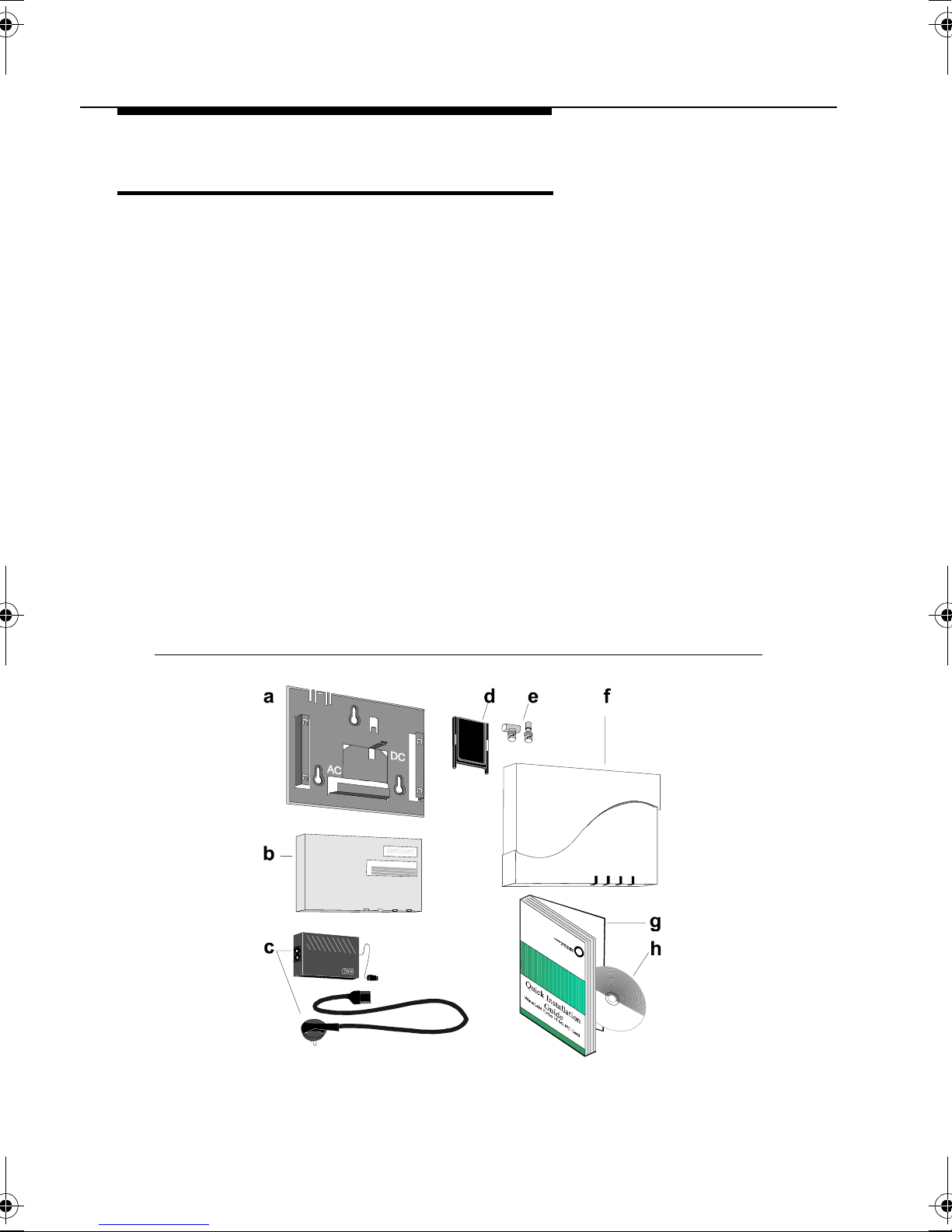
Kit Contents 1
a. Mounting plate to mount the WavePOINT-II unit to a wall.
b. WavePOINT-II Processor Module.
c. Power Supply & AC Power Cord.
d. Slot Protector Card.
(to protect unused PC Card slots from dust).
e. T-Connector and terminator for Ethernet 10Base2.
f. WavePOINT-II cover plate.
g. WavePOINT-II Quick Installation Guide (this document).
h. WaveLAN Software CD-ROM containing:
■ WaveMANAGER/AP Management and Dia gnos ti cs
software.
■ WavePOINT-II Software (also referred to as firmware).
■ Wa veMANA GER Use r’s Guide (a detai led refe rence gu ide
for designing and managing your wireless LAN system).
Figure 1-3 WavePOINT-II Kit Contents
1-8 WavePOINT-II - Quick Installation Guide
Page 17

Welcome
Selecting the Right WaveLAN Card
Selecting the Right WaveLAN Card 1
To install a WavePOINT-II device, you will need at least one
WaveLAN interface card. This card is not included with your
WavePOINT-II Kit, but must be ordered as an additional item.
Y our WavePOINT -II device supports the following WaveLAN cards,
allowing you to build the wireless network that suits your
requirements:
■ WaveLAN IEEE Adapters
■ WaveLAN Legacy Adapters (see page 1-14).
WaveLAN IEEE Adapters 1
WaveLAN IEEE Adapters are Type II extended PC-Cards with
integrated radio module and antennas (2.4 GHz). Y ou can use
your WavePOINT-II device in combination with any of the following
WaveLAN IEEE PC Cards:
■ WaveLAN/IEEE Turbo 11 Mb PC Card.
■ WaveLAN/IEEE Turbo PC Card.
■ Standard WaveLAN/IEEE 802.11 PC Card.
■ Fixed Wireless PC Card.
The difference between each of these card types is described on
the following pages.
WaveLAN/IEEE Turbo 11 Mb PC Card 1
The WaveLAN/IEEE 802.11 Turbo 11 Mb PC Card is a wireless
network adapter card that complies with the IEEE 802.11 standard
on wireless LANs Rev. B. This card that supports data rates up to
11 Mbit/s is available in two variants:
■ WaveLAN IEEE 802.11 Silver Label, and
■ WaveLAN IEEE 802.11 Gold Label.
WavePOINT-II - Quick Installation Guide 1-9
Page 18

Welcome
Selecting the Right WaveLAN Card
WaveLAN/IEEE Turbo PC Card 1
The WaveLAN/IEEE Turbo PC Card is a wireless network adapter
card that supports two proprietary (High & Medium) data rates, and
two data rates (Standard & Low) that comply with the IEEE 802.1 1
standard on wireless LANs Rev. A.
The WaveLAN/IEEE Turbo PC Card is available in two variants:
■ WaveLAN IEEE 802.11 Bronze Label, and
■ WaveLAN IEEE 802.11 Silver Label.
The WaveLAN/IEEE Turbo PC Card was marketed prior to the
release of Revision B of the IEEE 802.11 standard on wireless
LANs, which defines the standard for high-speed wireless LANs.
With the release of Revision B of the 802.11 standard, the
PC Card
PC Card
has been replaced with the
, described on the previous page1.
WaveLAN/IEEE Turbo 11 Mb
Standard WaveLAN/IEEE 802.11 PC Card 1
The standard WaveLAN IEEE 802.1 1 adapter is a wireless network
adapter card that complies with the IEEE 802.11 standard on
wireless LANs Rev. A. This card that supports data rates up to 2
Mbit/s is available in two variants:
■ WaveLAN IEEE 802.11 Bronze Label, and
■ WaveLAN IEEE 802.11 Silver Label.
Occasionally you may encounter WaveLAN/IEEE cards that are
identified by a white label, which support the same features as
Standard Bronze Label cards.
Turbo
1 The data rates “High & Medium” of these two cards are coexistent,
but not compatible: See page 1-13 for more information.
1-10 WavePOINT-II - Quick Installation Guide
Page 19

Welcome
Selecting the Right WaveLAN Card
Fixed Wireless PC Card 1
This card is a special WaveLAN PC Card for outdoor antenna
installations that is marketed in Europe only. It is typically used in
combination with WavePOINT-II access points and/or the
WaveLAN Vehicle-Mount Antenna to connect a wireless LAN
device to an outdoor antenna installation.
The Fixed Wireless PC Card can be recognized from the distinct
red color of the extended part of the PC Card. It supports the same
networking capabilities as the other WaveLAN cards, but has
different radio specifications, to comply with radio regulations for
outdoor antenna installations as defined by the European
Telecommunications Standards Institute (ETSI).
Just like the cards described on the previous pages, the Fixed
Wireless PC Card is available in the various Label variants.
For more details about this card, please consult Appendix A of the
Quick Installation Guide that came with your WaveLAN PC Card
and/or the “WaveLAN Outdoor Antenna Installation Guide” that
can be downloaded from the WaveLAN website.
WavePOINT-II - Quick Installation Guide 1-11
Page 20

Welcome
Selecting the Right WaveLAN Card
Bronze, Silver & Gold Labels 1
As you have noticed the various types of WaveLAN PC Cards
come in different variants identified by a specific label.
Bronze Label cards support the following features:
■ Interoperabilit y with other IEE E 802. 11 compliant Direct
Sequence radio devices.
■ Auto Transmit Rate selection in the range of “High, Medium
1
Standard and Low”
■ Frequency Channel Selection (2.4 GHz).
■ Roaming over multip le ch anne ls .
■ Power Management.
.
WaveLAN/IEEE Bronze cards are fully inter-operable with the
Silver & Gold cards and the WaveLAN cards with a white label.
Silver Label cards support the same functionality as the Bronze
cards. Silver cards however also support “Wired Equivalent
Privacy” (WEP) data encryption, based on the 64 bit RC4
encryption algorithm as defined in the IEEE 802.11 standard on
wireless LANs.
Gold Label cards, which exist for the WaveLAN/IEEE Turbo 11
Mb PC Card only, support an enhanced type of data encryption,
based on the 128 bit RC4 algorithm.
NOTE:
The WaveLAN/IEEE Turbo 11 Mb Gold PC Card may not
be marketed in all parts of the world, subject to national
legislation or local regulations. For availability in your
country, please consult your local Lucent Technologies
Sales Office.
1 Standard WaveLAN/IEEE PC Cards only support “Standard & Low”.
1-12 WavePOINT-II - Quick Installation Guide
Page 21

Welcome
Selecting the Right WaveLAN Card
Can I Use Different Card Types Together? 1
The answer is yes, however since the PC Cards differ in design
and features, you need to be aware of the constraints listed below.
Transmit Rate Compatibility 1
When using different card types, the WaveLAN PC Cards will
automatically synchronize their transmit rate to the highest
compatible data rate as supported by both cards.
This means that WaveLAN/IEEE Turbo 11 Mb PC Cards will use:
■ High or Medium data rate, when communicating with other
WaveLAN/IEEE Turbo 11 Mb PC Cards.
■ Standard or Low data rate, when communicating with:
— WaveLAN/IEEE Turbo PC Cards.
— Standard WaveLAN/IEEE 802.11 PC Cards.
WaveLAN/IEEE Turbo PC Cards will use:
■ High or Medium data rate, when communicating with other
WaveLAN/IEEE Turbo PC Cards.
■ Standard or Low data rate, when communicating with:
— WaveLAN/IEEE Turbo 11 Mb PC Cards.
— Standard WaveLAN/IEEE 802.11 PC Cards.
Transmissions at high data rates do not cover the same distances
as wireless data transmitted at Standard or Low data rates.
If you plan to upgrading an existing WaveLAN installation by
replacing the WaveLAN cards in your WavePOINT-II devices with
Turbo 11 Mb PC Cards, you are advised to perform a site survey
again in order to verify that the entire coverage area allows for data
transmissions at the highest transmit rates.
Consult the WaveMANAGER User’s Guide for information about
using the WaveMANAGER/CLIENT IEEE tool to perform such a
site survey.
WavePOINT-II - Quick Installation Guide 1-13
Page 22

Welcome
Selecting the Right WaveLAN Card
Data Enc ryption 1
When using WaveLAN data encryption in your network, you must
ensure that all WaveLAN devices will be:
■ Equipped with WaveLAN PC Cards that support encryption.
■ Configured with a matching set of encryption keys.
This means that you shou ld co nfig ur e Turbo 11 MB Gold cards
with 64-bit key values that match the values of the Silver cards.
WaveLAN Legacy Adapters 1
WaveLAN Legacy adapters exist in the following variants:
■ WaveLAN/PCMCIA Kit
■ WaveLAN/EAM Kit
These two types of WaveLAN adapters are no longer marketed by
Lucent Technologies. However as you may still encounter these
adapters in existing WaveLAN installations, they are briefly
described in this document.
WaveLAN/PCMCIA and WaveLAN/EAM exist with or without a
factory installed Security Feature (AES or DES) to encrypt all data
transmitted via the WaveLAN interface(s) of the WavePOINT-II.
WaveLAN/PCMCIA Kit 1
The WaveLAN/PCMCIA kit consists of a Type II PC-Card and radio
module (915 MHz or 2.4 GHz) that are connected via a small
cable. Standard cable length is 45 cm, optionally available are kits
that use a 100 cm cable.
1-14 WavePOINT-II - Quick Installation Guide
Page 23

Welcome
Selecting the Right WaveLAN Card
WaveLAN/EAM Kit 1
The External Antenna Module (EAM) is a type-II PC Card with
special radio module (915 MHz or 2.4 GHz) that provides an
interface to an external directional antenna.
■ Legacy WaveLAN Omni-Directional Antenna for indoor use
that, in combination with the WaveLAN/EAM, allows for more
flexibility in placement of the antenna for the WavePOINT-II
unit.
■ Legacy WaveLAN Outdoor kit, that allow for connecting the
WavePOINT-II to an outdoor antenna installation.
Figure 1-4 Legacy WaveLAN Omni-Directional Antenna
WaveLAN IEEE versus Legacy WaveLAN 1
Both WaveLAN IEEE and Legacy WaveLAN products use Direct
Sequence Spread spectrum modulation, to transmit and receive
wireless communications via the license-free 2.4 GHz radio
frequency band.
WavePOINT-II - Quick Installation Guide 1-15
Page 24

Welcome
Selecting the Right WaveLAN Card
Still, WaveLAN IEEE and Legacy WaveLAN should be considered
co-existent rather than compatible with one another.
■ Although the user can select the same radio channels for both
types of WaveLAN products, different generation products can
not communicate with one another directly.
■ Not all features supported by WaveLAN IEEE systems are
supported by Legacy WaveLAN systems and vice versa.
The main reason for the difference between WaveLAN IEEE and
Legacy WaveLAN products, is the fact that WaveLAN IEEE was
designed for interoperability with other wireless LAN devices that
the
comply with
The IEEE 802.11 Standard for Wireless LANs
industry standard for LAN communications;
1
.
However as WavePOINT-II allows you to use both Legacy
WaveLAN and WaveLAN IEEE 802.11 adapter cards
simultaneously, this should not prevent you from building the
WaveLAN Infrastructure that allows for smooth migration from
WaveLAN Legacy to WaveLAN IEEE network systems.
1 Standard defined by the 802.11 committee of the Institute of
Electrical and Electronics Engineers Inc. (IEEE).
1-16 WavePOINT-II - Quick Installation Guide
Page 25

Welcome
Optionally Available Products
Optionally Available Products 1
■ WaveLAN IEEE 802.11 Range Extender Antenna
An omni-directional antenna for indoor use that enables you to
extend the wireless range of the WavePOINT-II unit when
connected to an WaveLAN IEEE 802.11 PC Card.
■ WaveLAN IEEE 802.11 Vehicle Mount Antenna
A more ruggedized omni-directional antenna for outdoor use
that allows for mounting an external WaveLAN antenna in an
industrial envir on men t.
■ IEEE 802.11 Outdoor Antenna Kit
A complete outdoor antenna kit that includes a WaveACCESS
LINK WP-II, Lightning Arrestor, Outdoor Antenna Cable and 14
dBi directional or 7 dBi omni-directional antenna.
Figure 1-5 IEEE 802.11 Range Extender Antenna
WavePOINT-II - Quick Installation Guide 1-17
Page 26

Page 27

Installing the WavePOINT-II
2
Introduction 2
This chapter describes how to:
■ Install the WavePOINT-II hardware.
■ Install the WaveLAN interface(s).
■ Power up the device to start operation in Basic Access mode.
What You Need to install the WavePOINT-II kit is:
■ One WavePOINT-II unit.
■ One or more WaveLAN network interface cards.
■ (Optional) An Ethernet backbone
(either 10Base-T or 10Base2).
WavePOINT-II Placement 2
You can mount the WavePOINT-II on a vertical surface like a wall
or place the unit on a flat surface such as a table or cabinet.
Prior to mounting it to a fixed location, you may consider
performing a site survey to determine optimal placement for your
WavePOINT-II unit(s).
WavePOINT-II - Quick Installation Guide 2-1
Page 28

Installing the WavePOINT-II
Introduction
!
CAUTION:
Placement of the WavePOINT-II must satisfy the following
installation re qui re men ts :
a. Connect the unit to a grounding type AC wall outlet
(100-240 VAC) using the standard power cord as
supplied with the unit.
b. Placement must allow for easily disconnecting the
WavePOINT-II unit from the AC wall-outlet.
c. Do not cover the unit, or block the airflow to the unit
with any other objects. Keep the unit away from
excessive heat and humidity and keep the unit free
from vibration and dust.
d. Installation must at all times conform to local
regulations.
e. When the WavePOINT-II unit will be connected to an
outdoor antenna system, consult the documentation
that came with the outdoor antenna kit for additional
regulatory information, safety instructions and
installation re qui re men ts .
Indoor Antenna Placement 2
The integrated antennas of your WaveLAN card perform best in an
open environment with as few obstructions as possible. In most
situations mounting the WaveLAN radio module as pictured in
Figure 2-4 on page 2-8 or Figure C-1 on page C-1, will provide
satisfactory performance results. To ensure the best performance:
■ Place the WavePOINT-II as high and as centrally as possible
(relative to the WaveLAN stations in the vicinity).
■ Do not conceal the antenna.
■ (Optional) Use the WaveLAN card in combination with an
external antenna.
2-2 WavePOINT-II - Quick Installation Guide
Page 29

Installing the WavePOINT-II
Introduction
NOTE:
If you plan to use your WavePOINT-II device in
combination with two WaveLAN cards, you are advised to
connect at an external antenna to at least one of the two
WaveLAN cards. This external antenna should be
mounted as far away as possible from the other WaveLAN
card to allow maximum performance (see also “Optionally
Available Products” on page 1-17).
Outdoor Antenna Placement 2
The WavePOINT-II device has been designed for indoor
placement. Optionally you can connect the device to an outdoor
antenna installation using the Lucent Technologies Outdoor
Antenna Kit solution, according the instructions described in the
WaveLAN IEEE Outdoor Antena Installation Guide. You can
download this document from the WaveLAN website at
http://www.wavelan.com.
WavePOINT-II - Quick Installation Guide 2-3
Page 30

Installing the WavePOINT-II
Hardware Installation
Hardware Installation 2
The hardware installation of the WavePOINT-II access point is
summarized as follows:
1. Verifying Kit Contents.
2. Registering your WaveLAN Products.
3. Placing Mounting Plate and Power Supply.
4. Connecting the Network Interfaces.
5. Mounting the WavePOINT-II Cover Plate.
Verifying Kit Contents 2
1. Unpack the WavePOINT-II and verify that all items are present
as described in “Kit Contents” on page 1-8.
2. Unpack the W a veLAN networ k inte rface c ard(s ) and ve rify that
all items are present as described in the User’s Guide that
came with your WaveLAN Kit(s).
Regist ering your WaveLAN Products 2
Before you proceed, write down the following values of the
following components that you are about to install:
■ Serial Number and MAC Address of the WavePOINT-II unit.
■ Serial Number and MAC Address of the WaveLAN network
interface card s.
You will need these numbers later to identify the unit when running
the WaveMANAGER/AP (Access Point) program.
A form for recording this information is provided in Appendix B
”WavePOINT-II Start-up Configuration”.
2-4 WavePOINT-II - Quick Installation Guide
Page 31
Installing the WavePOINT-II
Hardware Installation
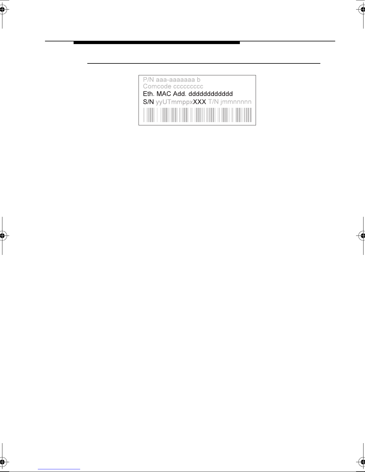
Figure 2-1 WavePOINT-II Iden tification Label
The Serial Number and MAC Address of the WavePOINT-II are
printed on a small label at the top right side of the processor
module as pictured in Figure 2-1.
For WaveLAN IEEE cards, this information is printed on a small
label at the back side of the PC Card.
■ The Ethernet MAC Address is used to identify the
WavePOINT-II device on the network.
■ When using the WavePOINT -II unit in combination with
WaveLAN Legacy cards, the last three digits of the unit’s
Serial Number (S/N) are important as well: These three digits
preceded by the letter ‘A’ or ‘B’ will identify the initial Network
ID (NWID) of the WaveLAN Legacy interface, where ‘A’ or ‘B’
will represent the slot of the processor module into which you
inserted the WaveLAN Legacy card.
WavePOINT-II - Quick Installation Guide 2-5
Page 32
Installing the WavePOINT-II
Hardware Installation
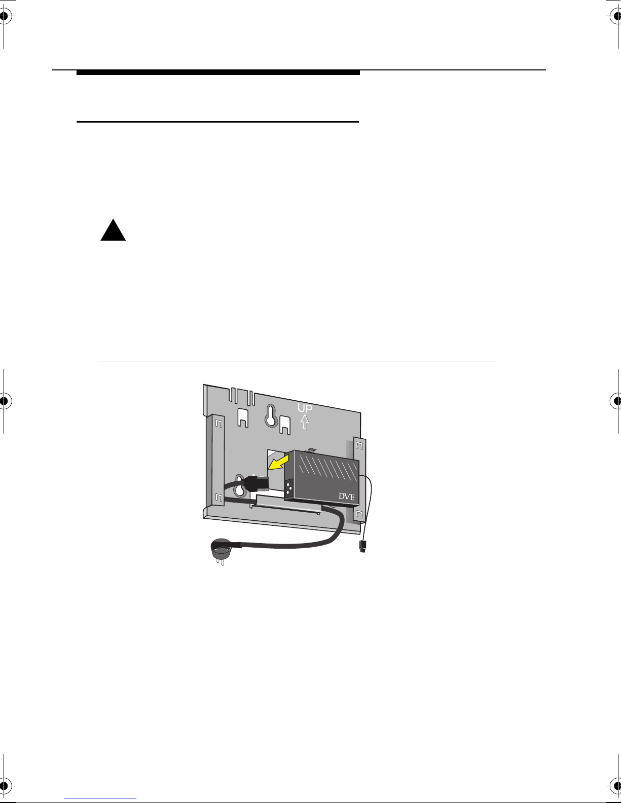
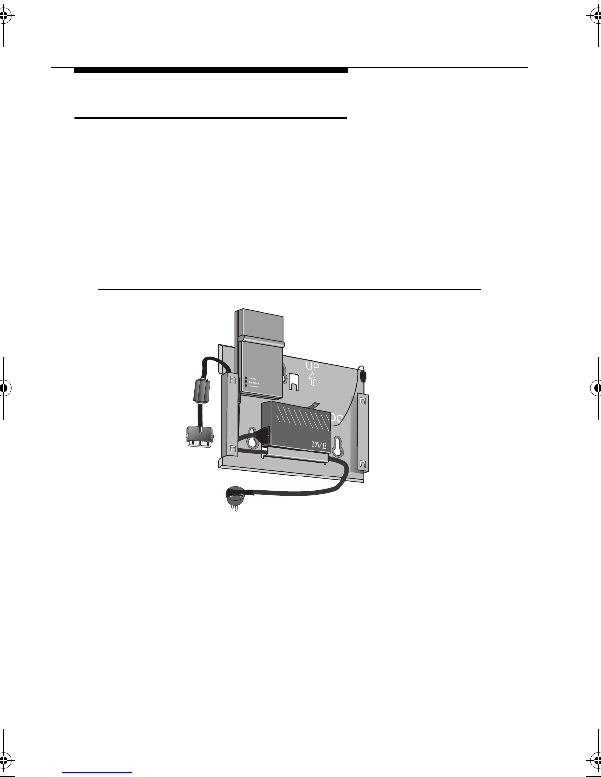
Placing Mounting Plate and Power Supply 2
1. Use the screws and plugs provided to fix the mounting plate of
the WavePOINT-II in the chosen position.
Note that the mounting plate is positioned correctly as pictured
in Figure 2-2, (the marked arrow pointing upwards).
!
WARNING:
The Mounting Plate of the WavePOINT-II access point has
not been designed for ceiling mounting. In environments
where the unit will be exposed to vibrations, ceiling
mounting might cause the processor module to slide off
the mounting plate, causing severe personal injury and/or
damage to your WaveLAN equipment.
Figure 2-2 Mounting th e Power Supply
2. Connect the AC power cord to the power supply unit and
mount the power supply unit at the mid section of the mounting
plate as pictured in Figure 2-2.
Depending on the actual location of the AC wall outlet, you
may choose to route the power cord differently to suit your
installation re qui re men ts .
2-6 WavePOINT-II - Quick Installation Guide
Page 33
Installing the WavePOINT-II
Hardware Installation
3. Use the tie-wraps provided to secure the power cord to the
small loops on the mounting plate at the position where the
cords will leave the unit.
According to the type of WaveLAN adapter that you plan to install,
the next steps and illustrations may differ:
■ For WaveLAN IEEE PC Cards proceed as described under
“Mounting the Processor Module” on page 2-7 .
■ For WaveLAN Legacy network interface cards, please refer to
Appendix C ”Additional Installation Instructions” prior to
mounting the Processor Module.
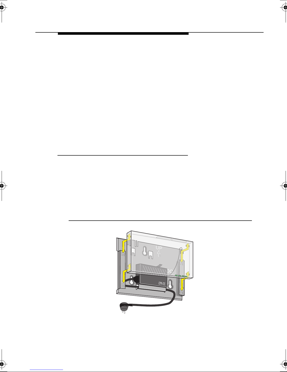
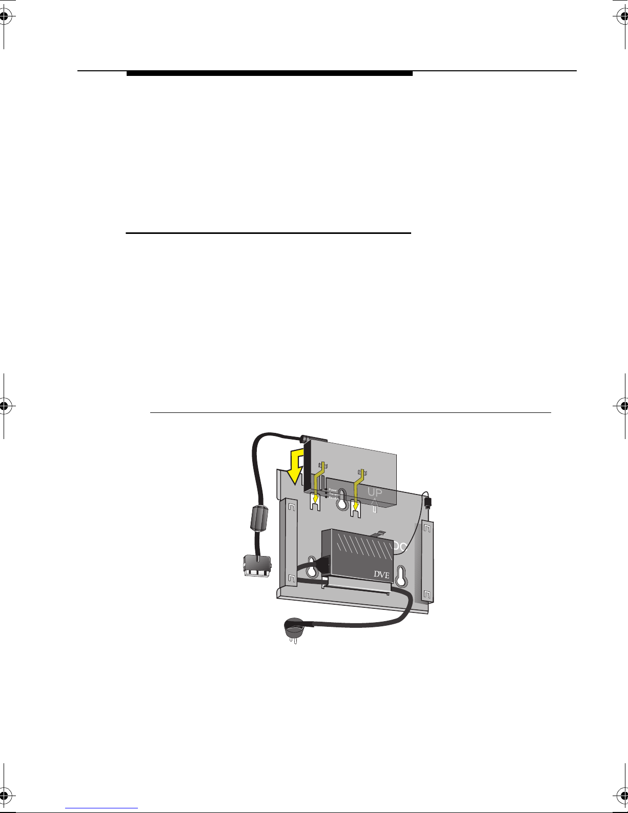
Mounting the Processor Module 2
1. Connect the DC power cable to the DC power inlet of the
processor module.
2. Bring the rear side of the processor module on to the mounting
plate, sliding the four recesses of the module over the
corresponding tabs on the mounting plate.
3. Press firmly to assure the unit is properly attached.
Figure 2-3 Attaching the Processor Module
WavePOINT-II - Quick Installation Guide 2-7
Page 34
Installing the WavePOINT-II
Hardware Installation
!
CAUTION:
Before you proceed:
Verify that all four recesses are fitted correctly onto the
corresponding tabs of the mounting plate. If the processor
module is not properly seated, it may drop causing severe
personal injury and/or causing serious damage to the
WavePOINT-II unit.
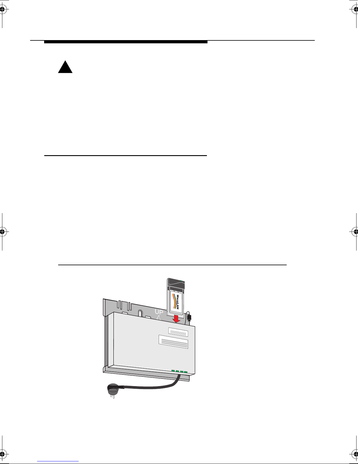
Connecting the Network Interfaces 2
One PC Card slot of the WavePOINT-II access point is equipped
with a plastic Slot Protector Card. The purpose of this card is to
protect the WavePOINT-II unit from dust when the access point is
used with a single WaveLAN interface only.
When you intend to install two WaveLAN interfaces into your
WavePOINT-II access point, first take out the Slot Protector Card.
You are advised to keep the Slot Protector Card for situations
when you would like to change the WavePOINT-II hardware
configuration in the future.
Figure 2-4 In serting the WaveLAN Card
2-8 WavePOINT-II - Quick Installation Guide
Page 35
Installing the WavePOINT-II
Hardware Installation
1. Insert your WaveLAN PC Card(s) into the processor module.
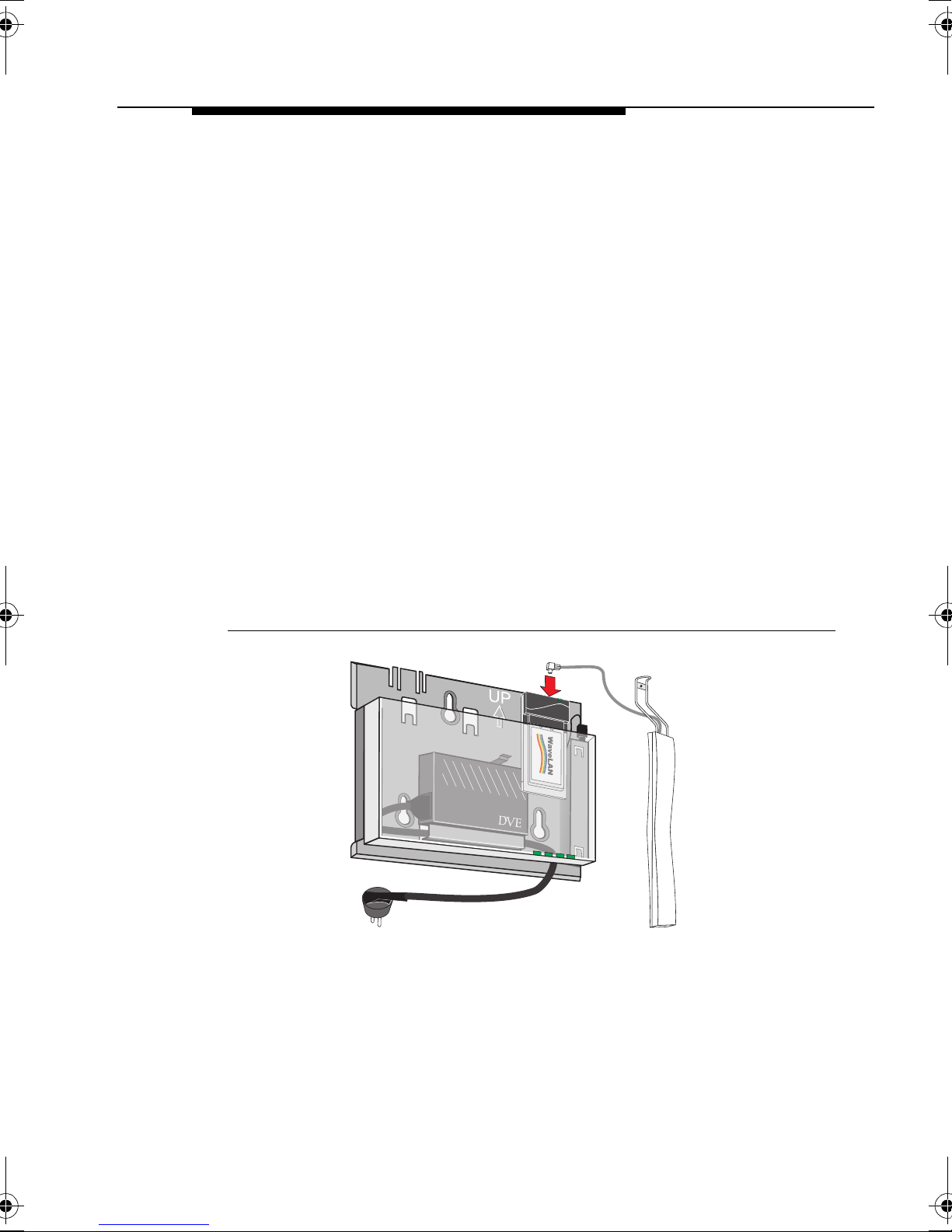
2. (Optional) When you intend to use the WavePOINT-II access
point with the WaveLAN Range Extender Antenna (not
included):
a. Remove the protective cap from the external antenna
connector on your WaveLAN IEEE PC Card.
b. Insert the cable connector into the external antenna
connector on your WaveLAN IEEE PC Card.
c. Press gently until the connector ‘clicks’ into place.
If you do not feel or hear a click, carefully maneuver the
connector until it clicks into position.
d. Mount or place the Range Extender Antenna into a vertical
position to ensure optimal performance.
If you are installing the WavePOINT-II with two WaveLAN
cards, mount the external antenna(s) away from one another
as far as possible to allow maximum performance.
Figure 2-5 Connecting the Range Extender Antenna
3. (Optional) Connect the Ethernet cable to the Ethernet
interface:
■ 10Base-T (RJ 45 Connector) or
■ 10Base2 (BNC Connectors, T- Connector provided)
WavePOINT-II - Quick Installation Guide 2-9
Page 36

Installing the WavePOINT-II
Hardware Installation
The WavePOINT-II will automatically select the type of the
connected Ethernet interface, so you will not need to set any
switches.
NOTE:
You are advised to apply the 10Base2 Ethernet terminator
(included with your WavePOINT-II Kit) to the Processor
Module in any of the situations described on the following
page.
■ This is the last unit on a 10Base2 cable.
■ You intend to use the unit with two WaveLAN
interfaces only, not using the Ethernet interface at all.
4. (Optional) Use the tie-wraps provided to secure the Ethernet
cable to the small loops on the mounting plate at the position
where the cable will leave the unit.
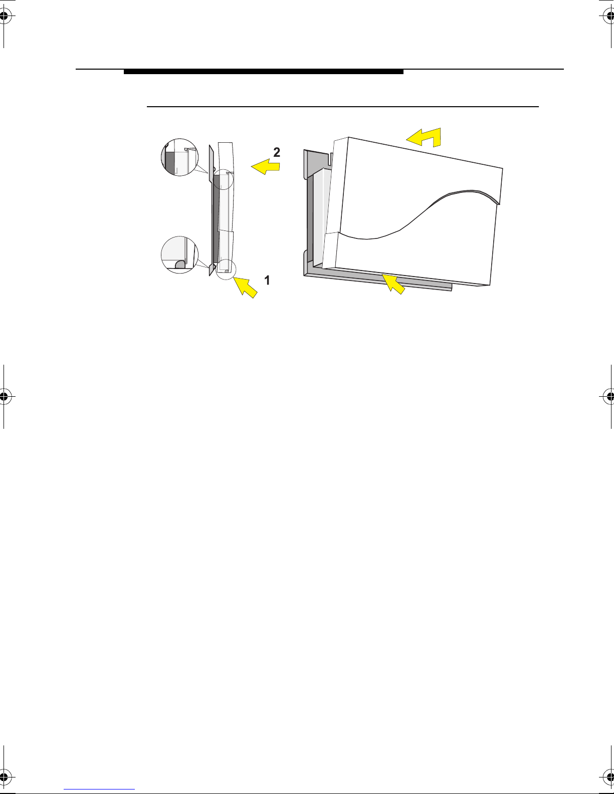
Mounting the WavePOINT-II Cover Plate 2
1. Mount the WavePOINT-II cover, (the LED windows at the
lower right-hand side).
Position the latches at the inside of the cover underneath the
rim at the bottom of the processor module (see arrow 1 in
Figure 2-6).
2-10 WavePOINT-II - Quick Installation Guide
Page 37
Installing the WavePOINT-II
Hardware Installation
Figure 2-6 Mounting the WavePOINT-II Cover Plate
2. Gently press the top of the cover plate towards the unit until it
clicks (see arrow 2 in Figure 2-6).
3. Verify the unit is properly seated and power up the unit as
described on “Powering-up WavePOINT-II” on page 2-12.
WavePOINT-II - Quick Installation Guide 2-11
Page 38

Installing the WavePOINT-II
Powering-up WavePOINT-II
Powering-up WavePOINT-II 2
The WavePOINT-II power supply accepts any input AC voltage in
the range of 100-240 VAC.
!
WARNING:
For your own safety , use only the power cord supplied with
the unit. Insert it in a grounded AC wall outlet.
When using the unit in combination with outdoor antennas,
the grounding of the AC wall outlet must be connected to
the safety grounding system of the outdoor antenna
system and the WaveLAN Lightning Protector.
When powered on, the WavePOINT-II unit will perform start-up
diagnostics characterized by a LED sequence. The WavePOINT-II
LEDs will change color in the range Amber, Red and Green.
When finished (after approximately 60 seconds) the WavePOINT- II
unit will start bridging operation characterized by the LED activity
as listed in Table 2-1 below.
Table 2-1 LED Activity Table:
LED Definition Activity
1
Description
Power Green Power enabled
Ethernet Flicker Green Ethernet LAN activity
A
WaveLAN A Flicker Green WaveLAN activity on socket A
B
WaveLAN B Flicker Green WaveLAN activity on socket B
1 LED activity will only occur when there is network activity on the
corresponding WavePOINT-II interface.
If the WavePOINT-II does not switch to normal operation within two
minutes, please consult the troubleshooting section of the
WaveMANAGER IEEE User’s Guide.
2-12 WavePOINT-II - Quick Installation Guide
Page 39

Beyond Quick-Start...
3
Introduction 3
Once you have powered up your WavePOINT-II hardware, you will
have completed the WavePOINT-II ‘Quick Start’. This chapter will
take you ‘Beyond Quick Start’ and briefly explain how to:
■ Connect Stations to your WavePOINT-II
■ Configure your WavePOINT-II
For more de tails, co nsult th e W aveMANAG ER IEEE Us er’s Guide
or the on-line help system of the WaveMANAGER/AP program.
1
Connect Stations to your WavePOINT-II 3
When powering up WavePOINT-II for the first time, the unit will
start bridging operation in Access Point mode, using the WaveLAN
parameters as listed in Appendix B ”WavePOINT-II Start-up
Configuration”.
The Access Point mode enables you to connect wireless stations
to the WavePOINT-II, provided that these stations have been
configured to use WaveLAN parameter values that match the
configuration of your WavePOINT-II.
1 A special edition of this document for WaveLAN Legacy systems can be
downloaded from the WaveLAN website.
WavePOINT-II - Quick Installation Guide 3-1
Page 40

Beyond Quick-Start...
Introduction
WaveLAN IEEE Systems 3
In WaveLAN IEEE infrastructures, all WavePOINT-II devices and
wireless stations must use the same WaveLAN Network Name
Alternatively you can (re-)configure the stations to use the value
“ANY” (all upper-case) to allow a station to connect to the first
WavePOINT-II it can find.
Once the WaveLAN IEEE stations has the correct WaveLAN
Network Name, it will automatically select the correct radio channel
and establish the connection with the WavePOINT-II.
WaveLAN Legacy Systems 3
For WaveLAN Legacy systems, all WavePOINT-II devices and
wireless stations must use identical values for the following
parameters:
1
.
■ Domain ID.
■ Frequency Channel .
■ Beacon Key.
!
CAUTION:
The start-up configuration of WavePOINT-II works fine for
testing the equipment and/or performing site surveys.
To avoid unintended interference with neighboring
networks, or unauthorized access to your network you are
advised always to modify this configuration to define
unique values for your WaveLAN Network.
Consult the WaveMANAGER IEEE User’s Guide for more
information and instructions.
1 This parameter corresponds to the “ESSID” (Extended Service Set ID) as
defined in the IEEE 802.11 Standard for Wireless LANs.
3-2 WavePOINT-II - Quick Installation Guide
Page 41

Beyond Quick-Start...
Introduction
Configure your WavePOINT-II 3
To view or modify the Start-up Configuration of your WavePOINT-II
unit, you will need to install the WaveMANAGER/AP software that
came with your WavePOINT-II unit.
The WaveMANAGER/AP program enables you to:
■ Configure your WavePOINT-II access points and/or
WaveACCESS LINK WP-II device(s).
■ Monitor the performance of the WavePOINT-II access points
and/or WaveACCESS LINK WP-II device(s).
The WaveMANAGER/AP program requires a TCP/IP networking
protocol to communicate with the WavePOINT-II devices. To allow
proper addressing via TCP/IP:
■ You must assign a unique IP Address to each WavePOINT-II
device in your network.
■ The computer that you will use to run the WaveMANAGER/AP
program must have the TCP/IP protocol installed and an IP
Address (assigned manually or via BootP or DHCP server).
WaveMANAGER Station Requirements 3
To install the WaveMANAGER/AP software, select a networked
computer that satisfies the following requirements:
■ A 80486 or later processor.
■ Free disk space of 4 Mb.
■ 8 Mb RAM (16 Mb or more recommended).
■ Microsoft Windows 95, Windows 98 or Windows NT (v.4.0)
operating system.
■ An Ethernet or WaveLAN network adapter card.
■ A TCP/IP protocol installed.
WavePOINT-II - Quick Installation Guide 3-3
Page 42

Beyond Quick-Start...
Introduction
The computer you select would typically be the computer used by
the LAN Administrator. This computer can be any wired or wireless
desktop and/or laptop computer.
You may install the WaveMANAGER/AP software on multiple
computers, allowing you to use a combination of both wired and
wireless stations to administer your WaveLAN network.
The choice for a wireless or wired WaveMANAGER Station will
depend on your preferences and abilities to administer your
WaveLAN network, but for “out-of-the-box” WavePOINT -II devices,
your best bet is probably a wired Ethernet station.
Once the unit has been assigned a unique IP Address, you can
use any of the wired and/or wireless configuration scenarios as
described in the WaveMANAGER/IEEE User’s Guide.
Install the WaveMANAGER/AP Software 3
1. Insert the WaveLAN Software CD-ROM into the CD-ROM
drive of the computer that will be used as the
‘WaveMANAGER/AP Station’
2. Use your Windows Explorer to open the folder
software\bridge\accesspt" and locate the file "setup.exe"
"
3. Run the
the instructions as they appear on the screen.
The Setup Utility will create a special WaveLAN group in the
Windows Programs menu, providing you with the key to configure
your WaveLAN network to fit your requirements.
Previously installed versions of the WaveMANAGER/AP program
will automatically be replaced, without affecting any other file that
you might have saved into the program’s directory. For example if
you saved back-ups of WavePOINT-II configuration files which you
created with the previous version in the WaveMANAGER/AP
program folders, these files will not be deleted or overwritten.
SETUP.EXE file to start the installation utility, and follow
3-4 WavePOINT-II - Quick Installation Guide
Page 43
Beyond Quick-Start...
Introduction
Access the WavePOINT-II Configuration 3
The easiest way to access the Start-up configuration of your
WavePOINT-II devices, is to configure the devices one-by-one at
your desk via one of the following wired connections:
■ Connect Directly to the WaveMANAGER Station.
■ Connect via a Network Hub.
Connect Directly t o the WaveMANAGER Station 3
The WavePOINT-II supports two types of Ethernet cabling:
■ 10Base-T, also referred to as UTP (Unshielded Twisted Pair).
■ 10Base2, also referred to as Thin-coax with BNC connectors.
If you are using 10Base-T cables, you can only establish a “direct
connection” if you use a dedicated “crossover” cable as pictured in
Figure 3-1 (also referred to as “cross-wired” or “cross-connect”).
Figure 3-1 Connect via a 10Base-T Crossover Cable
If you are using 10Base2 cables, you must connect the cables
using standard BNC T-connectors, and apply terminators at the
open ends of the T-connectors.
WavePOINT-II - Quick Installation Guide 3-5
Page 44

Beyond Quick-Start...
Introduction
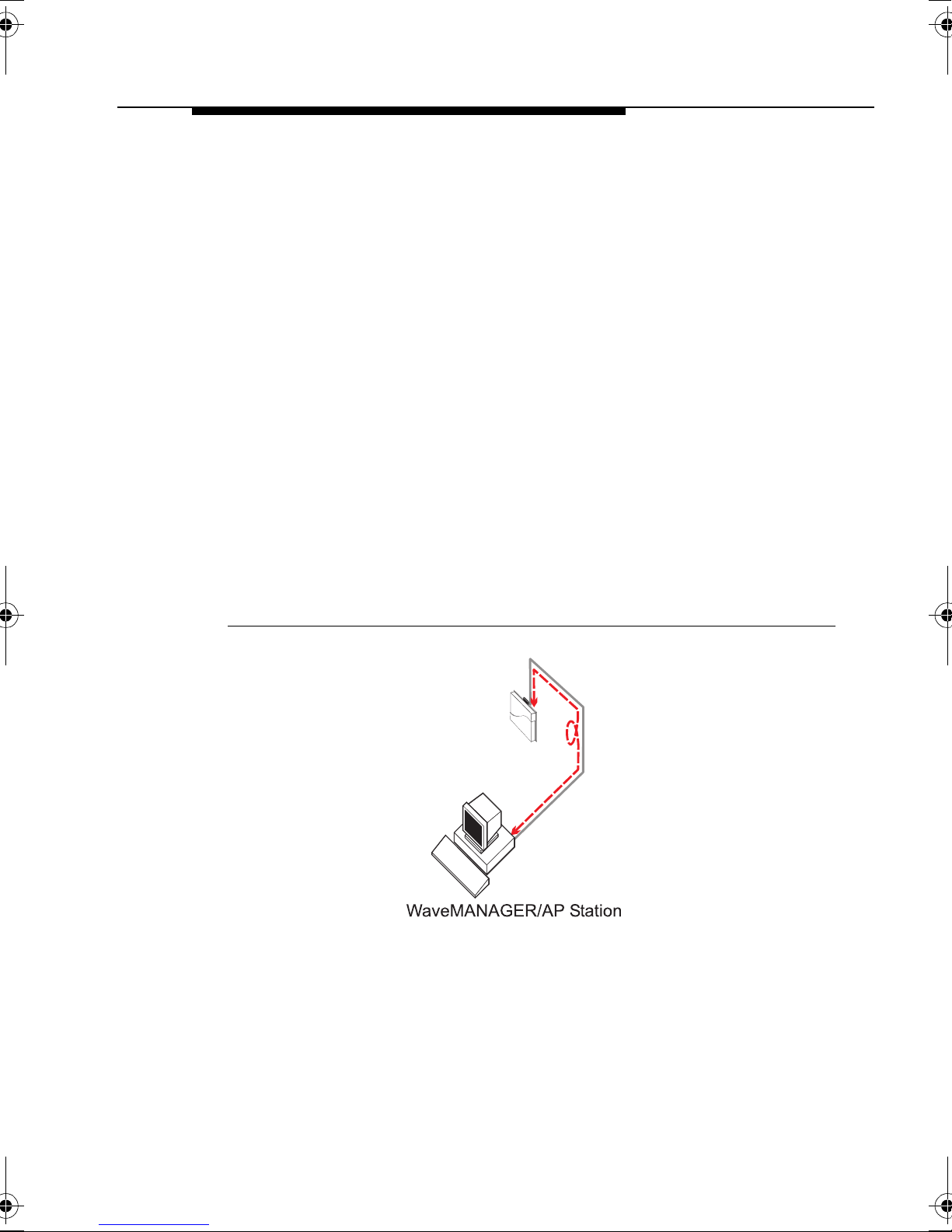
Connect via a Network Hub 3
An alternative way to connect the WavePOINT-II device to your
WaveMANAGER station is via a network hub, or patch panel as
pictured in Figure 3-2.
Figure 3-2 Connect via a Hub
This method is similar to most standard Ethernet 10Base-T cabling
systems. For “out-of-the-box” installations, the easiest way to
access the unit, is by connecting your WaveMANAGER station and
the WavePOINT-II device to the same hub, to ensure that both
devices are located on the same subnet.
Start WaveMANAGER/AP and Go.... 3
Congratulations! Having completed the steps in this Quick
Installation Guide you are ready to power up your wireless
installation.
Proceed with the instructions as described in the WaveMANAGER
User’s Guide to customize the configuration to meet your
networking requirements, monitor wireless performance and/or
optimize bridge performance.
3-6 WavePOINT-II - Quick Installation Guide
Page 45

WavePOINT-II Specifications
A
Hardware 1
Physical Specifications
Dimensions (HxWxL) 5x18.5x26 cm
Weight 1.75 Kg.
Power Cord Length 2.5 meter
Electrical Specifications
Voltage 100-240 V AC (50-60 Hz)
Current 0.2 Amp
Power Consumpti on 20 Watt
Environmental Specifications
Temperature Humidity
Operating 0° to 40° C 20 to 80% (relative humidity)
Transit -40° to 60° C 15 to 95% (no condensation allowed)
Storage -10° to 60° C 1 0 to 90% (no condensation allowed)
Ethernet Interface
10Base2 BNC f emale connector socket
(Terminator and T-connector provided)
10Base-T RJ 45 female socket
WaveLA N Interf a ce
PC Card Type II socket that can be used for:
■ IEEE 802.11 WaveLAN PC Card
■ WaveLAN/PCMCIA
■ WaveLAN/EAM
WavePOINT-II - Quick Installation Guide A-1
Page 46

WavePOINT-II Specifications
Software
Software 1
WavePOINT-II Operating Software
wpntxxx.bin Factory installed operating software for the
WavePOINT-II access point. This software that is
loaded into the FlashROM of the WavePOINT-II
device controls the features and functions of the
WavePOINT-II access poi nt.
The ‘xxx’ in the file name refer to the version level of
the software.
When new features and functionality become
available fo r the WavePO INT-II, you can upgr ade th e
WavePOINT-II by uploading the latest software to
your access points as described in the
WaveMANAGER IEEE User’s Guide.
WaveMANAGER/AP
wman_ap.exe Configuration and management software for
WavePOINT-II access points. This software runs on
Windows 95 and Windows NT (v4.0) platforms only.
A-2 WavePOINT-II - Quick Installation Guide
Page 47

WavePOINT-II Start-up
Configuration
B
Identify the Start-up Settings 2
Your WavePOINT-II access point comes with the WavePOINT-II
operating software factory installed. Together with this software,
the WavePOINT-II has also been loaded with a factory set
configuration, that allows for ‘out-of-the box’ operation.
NOTE:
The factory set configuration should not be confused with
a ‘default’ configuration. For example when performing a
‘Reboot’ or ‘Forced Reload’ (described in the
WaveMANAGER User’s Guide provided on the CD-ROM),
the unit will NOT return to the ‘factory-set’ configuration.
To connect to a WavePOINT-II, the WaveLAN parameters of each
wireless station should be configured to match the values as
identified for the WavePOINT-II unit.
■ When powering up WavePOINT-II for the very first time, these
values should match the values listed in Table B-1.
■ For normal operation these values should match the ones you
identified when configuring the WavePOINT-II unit. You are
advised to record this information this information on the
WavePOINT-II Configuration Record in this appendix.
■ When you set the WavePOINT-II device to ‘forced reload
mode’ these values should match the settings listed in the
WaveMANAGER IEEE User’s Guide.
WavePOINT-II - Quick Installation Guide B-1
Page 48

WavePOINT-II Start-up Configuration
Identify the Start-up Settings
France
Japan
All other countries
1
France
Japan
All other countries
Americas only
Must be unique for each cell.
3
IP Address 153.69.254.254
2.484 MHz
2.422 GHz
2.460 MHz
2.484 MHz
2.422 GHz
915 MHz
2
Encryption disabled
4
915 MHz
Subnet Mask 255.255.0.0
Read Password ‘public’
Read/Write Password ‘public’
RF-Channel 2.4 GHz 2.462 MHz
WaveLAN Network Name ‘WaveLAN Network’
Wireless Cell ID MAC Address of the IEEE 802.11 PC Card.
Medium Reservation Disabled
Transmit Rate Auto Rate Select
Encryption (Silver & Gold cards only) Disabled
RF-Channel 2.4 GHz
WaveLAN Network Name Domain ID 0001 Roaming enabled
Encryption Key 0
Beacon Key 0000 Key is disabled
Wireless Cell ID NWID SXXX
WavePOINT-II Identifiers
Table B-1 Fa ctory-set Start-up Configuration
IEEE 802.11 WaveLAN Interface
B-2 WavePOINT-II - Quick Installation Guide
WaveLAN Legacy Interface
hese values apply to new WaveLAN/PCMCIA Kits. When you use a previously installed kit, verify or correct the current operating
frequency using the WaveMANAGER/AP program.
8
1 When using IP networks, change this IP address to a unique address in the range assigned to your organization.
2
digits of the unit’s Serial number (see WaveLAN Legacy ).
3 S identifies the PC Card S ocket of the WavePOINT-II un it (A or B), containing the W aveLAN card. xxx repre sents the last three
4 Only when the WaveLAN/PCMCIA Kit has a factory installed Security Feature.
Page 49

WavePOINT-II Start-up Configuration
Identify the Start-up Settings
WavePOINT-II - Quick Installation Guide B-3
Page 50

Page 51

Additional Installation
Instructions
C
WaveLAN Legacy Radio Modules C
This Appendix describes additional instructions for:
■ Mounting the WaveLAN Legacy radio modules of the
WaveLAN/PCMCIA Kit and the WaveLAN/EAM Kit.
■ Removing the WavePOINT-II Cover Plate.
Figure C-1 Mounting the Legacy PCMCIA Radio
WavePOINT-II - Quick Installation Guide C-1
Page 52
Additional Installation Instructions
WaveLAN Legacy Radio Modules
Mounting the WaveLAN/PCMCIA Radio C
When you use your WavePOINT-II in combination with a
WaveLAN/PCMCIA Kit, you must mount the radio module prior to
mounting the WavePOINT-II Processor Module.
1. Mount the WaveLAN radio module to the mounting plate as
pictured in Figure C-1 on page C-1.
2. Guide the cable and connector of the radio module through the
vertical recess as pictured in Figure C-2, to allow the cable and
connector to run ‘free’ outside the mounting plate.
Figure C-2 Connecting the WaveLAN/PCMCIA Card
3. Connect the PC card to the cable of the radio module.
(Note that the tabs in both connectors will be properly aligned).
4. Proceed with WaveLAN Legacy .
When you would like to use the WavePOINT-II unit in
combination with a second WaveLAN Legacy interface:
■ Mount the second radio module outside the WavePOINT -II
device, separating the two radios as much as possible.
C-2 WavePOINT-II - Quick Installation Guide
Page 53
Additional Installation Instructions
WaveLAN Legacy Radio Modules
■ Use the bracket with the adhesive pads that came with
your WaveLAN/PCMCIA Kit to stick the module to a flat
surface such as a wall or post.
5. Proceed as described in Chapter 2, “Mounting the Processor
Module” on page 2-7
Mounting the WaveLAN/EAM Radio C
When you intend to use WavePOINT-II in combination with a
WaveLAN/EAM Kit, you must mount the EAM radio module prior to
mounting the WavePOINT -II Processor Module.
1. Mount the WaveLAN radio module to the mounting plate as
pictured in Figure C-3 on page C-3.
2. Guide the cable and connector of the radio module through the
vertical recess as pictur ed in Figu re C-4, to allow th e cable an d
connector to run ‘free’ outside the mounting plate.
Figure C-3 Mounting the Legacy EAM Radio
3. When using the standard WaveLAN Legacy omni-directional
antenna for indoor use (see WaveLAN Legacy ), connect the
antenna cable to the WaveLAN/EAM radio module.
WavePOINT-II - Quick Installation Guide C-3
Page 54

Additional Installation Instructions
WaveLAN Legacy Radio Modules
4. Use the tie-wraps provided to secure the antenna cable to the
WavePOINT-II mounting plate.
5. Connect the PC card to the cable of the radio module.
The tabs in both connectors must be properly aligned.
6. Proceed as described in Chapter 2, “Mounting the Processor
Module” on page 2-7.
If you intend to connect the WavePOINT-II to an outdoor antenna
system proceed as described below.
Connecting to an Outdoor Antenna System C
When installing an outdoor antenna system, like for example the
WaveLAN Outdoor Kit, you will need to apply the WaveLAN
Lightning Protector between your WaveLAN/EAM and the outdoor
antenna.
The WaveLAN Lightning Protector is a surge arrester to protect
your sensitive WaveLAN equipment from static discharge and
transients that occur at your outdoor antenna.
!
DANGER:
Do not work on ‘Outdoor Antenna Installations’ during
thunderstorms or lightning activity. The outdoor antenna
and antenna cables are electrical conductors. In case
lightning would strike the antenna during your installation
activities you might receive an electric shock resulting in
severe personal injury and/or damage to your WaveLAN
equipment.
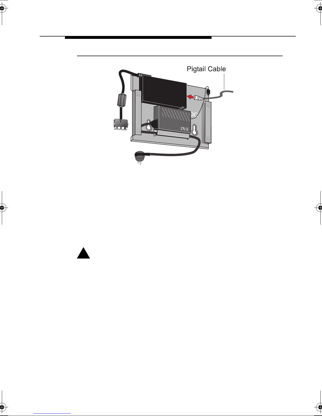
1. Once the WaveLAN/EAM radio is properly seated, according
the instructions as described on page C-3, connect the pigtail
cable to the WaveLAN/EAM radio as pictured in Figure C-4.
C-4 WavePOINT-II - Quick Installation Guide
Page 55
Additional Installation Instructions
WaveLAN Legacy Radio Modules
Figure C-4 Connecting the Pigtail and PCMCIA Card
2. Mount the WaveLAN Lightning Protector close to the
WavePOINT-II device.
The distance between the two items should allow sufficient
clearance to mount the WavePOINT-II cover plate, but should
not exceed the length of the pigtail cable.
3. Connect the WaveLAN Lightning Protector to the same
grounding system as the WavePOINT-II device and the
outdoor antenna system.
!
WARNING:
The WaveLAN Lightning Protector, the outdoor antenna
system and the WavePOINT-II unit must be connected to
the same ground, using an equipotential bonding
conductor. Always consult a qualified electrician if you are
in doubt as to whether your WaveLAN outdoor antenna
system is properly grounded.
WavePOINT-II - Quick Installation Guide C-5
Page 56

Additional Installation Instructions
WaveLAN Legacy Radio Modules
Figure C-5 Connecting the WaveLAN Lightning Protector
4. Connect the other end of the pigtail cable to the WaveLAN
Lightning Protector.
5. Use the tie-wraps provided to secure the pigtail cable to the
WavePOINT-II mounting plate.
6. Connect the PC Card to the cable connector of the EAM radio
module and proceed as described in Chapter 2, “Mounting the
Processor Module” on page 2-7 .
C-6 WavePOINT-II - Quick Installation Guide
Page 57
Additional Installation Instructions
Removing the Cover Plate
Removing the Cover Plate C
Removing the cover plate of the WavePOINT-II unit may be
required in one of the following situations:
■ You would like to change or replace the network interface(s) of
your WavePOINT -II access point, or
■ You would like to access the ‘Reboot’ and/or ‘Forced Reload’
buttons on the WavePOINT-II Processor Module.
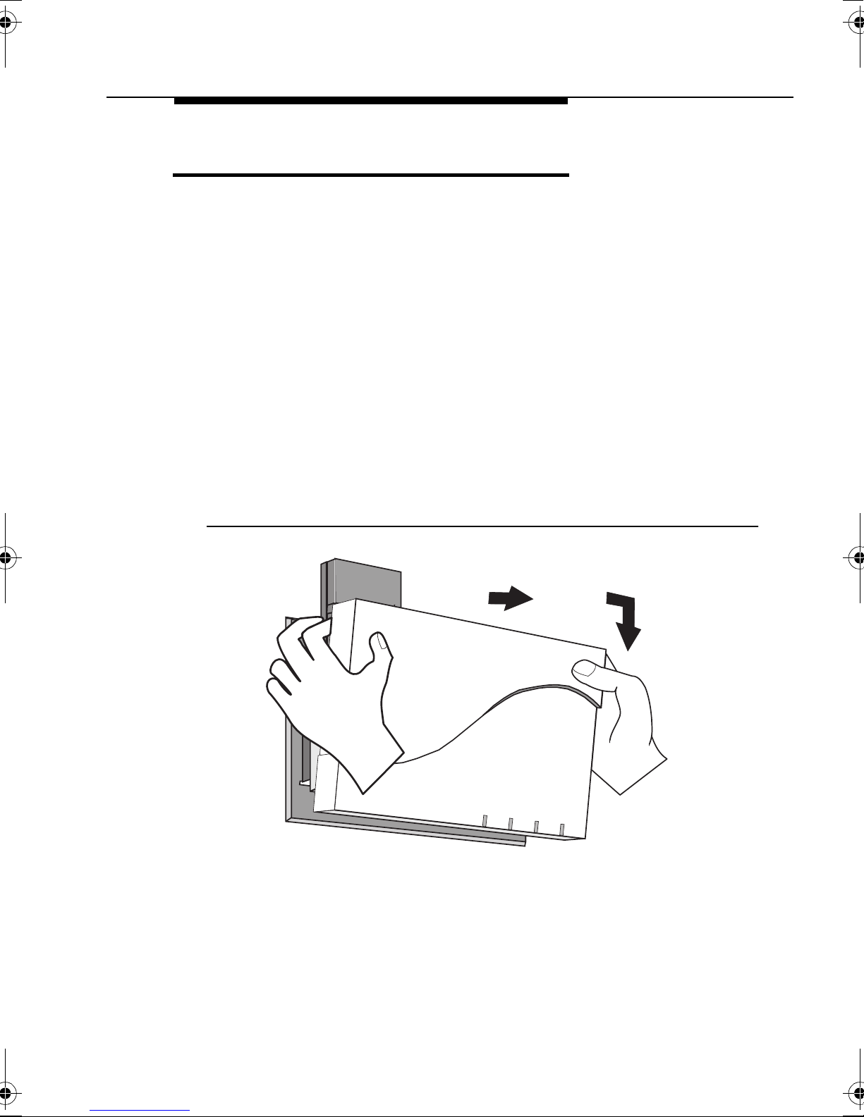
To remove the WavePOINT-II cover plate, proceed as follows:
1. To remove the cover of WavePOINT-II, place your hands on
the cover as pictured Figure C-6 on page C-7.
2. Gently pull the top of the cover towards you to release the
latches (located inside the cover).
Figure C-6 Removing the WavePOINT-II Cover Plate
1
2
3. Lower the cover to remove it from the processor module.
WavePOINT-II - Quick Installation Guide C-7
Page 58

Page 59

Warranty Repair Card
W
About Warranty and Repair W
In case your IEEE 802.11 WaveLAN product is not working
properly, you are advised to consult the Troubleshooting hints,
prior to contacting WaveLAN Technical Support.
In case your IEEE 802.11 WaveLAN product is defective, return it
to your Dealer/Distributor in the original packaging.
Warranty Repairs: W
When returning a defective product for Warranty, always include
the following documents:
■ The Warranty Repair card, and
■ A copy of the invoice/proof of purchase
All other Repairs: W
When returning a defective product for Repair, always include the
the Warranty Repair card
You are advised to read the Information about “Limited Warranty”
as described on the following page.
WavePOINT-II - Quick Installation Guide W-1
Page 60

Warranty Repair Card
Limited Warranty
Limited Warranty W
Lucent Technologies extends a limited warranty from date of
purchase of:
■ Thirty-six (36) months for WaveLAN hardware products
■ Twelve (12) months for WavePOINT access points
■ Twelve (12) months for for the media on which the software is
furnished and the reproduction of the software on the media.
Upon proof-of-purchase Lucent Technologies shall at its option,
repair or replace the defective item at no cost to the buyer.
Defective items shall be returned to the dealer/distributor:
■ Freight prepaid.
■ Accompanied by a copy of proof-of-purchase.
■ Accompanied by a filled out Warranty/Repair card.
This warranty is contingent upon proper use in the application for
which the products are intended and does not cover products
which have been modified without the seller’s approval or which
have been subjected to unusual physical or electrical demands or
damaged in any way.
This Warranty constitutes the sole and exclusive remedy of any
buyer or seller’s equipment and the sole and exclusive liability of
Lucent Technologies in con nection with the produ cts and is in lieu of
all other warranties, express, implied or statutory, including, but not
limited to, any implied warranty of merchantability of fitness for a
particular use and all other obligations or liabilities of Lucent
Technologies.
In no event will Lucent Technologies Inc. or any other party or
person be liable to you or anyone else for any damages, including
lost profits, lost savings or other incidental or consequential
damages, or inability to use the software provided on the software
media even if Lucent Technologies or the other party person has
been advised of the possibility of such damages.
W-2 WavePOINT-II - Quick Installation Guide
Page 61

Warranty Repair Card
W-3 WavePOINT-II - Quick Installation Guide
"
Reported Problem: Problem Description:
❑
Out-of-Box Failure
❑
Other
To be filled out by the User 0
Product Description :
COMCODE (Product ID) :
Serial Number:
Invoice Date: (dd/mm/yyyy)
Name:
Title:
Company:
Address:
City/State/Zipcode:
Country:
Telephone:
Fax:
Email:
To be filled out by the Dealer/Distributor 0
Dealer Name:
Address:
City/State/Zipcode:
Country:
Telephone:
Fax:
Warranty? Commen t:
❑
Yes
❑
No
RMA Reference
wp2_c.book Page 3 Thursday, September 23, 1999 6:24 PM
Page 62

Page 63

List of Figures
Figure 1-1 WavePOINT-II Access Point 1-2
Figure 1-2 WaveACCESS LINK WP-II 1-3
Figure 1-3 WavePOINT-II Kit Contents 1-8
Figure 1-4 Legacy WaveLAN Omni-Directional Antenna 1-15
Figure 1-5 IEEE 802.11 Range Extender Antenna 1-17
Figure 2-1 WavePOINT-II Identification Label 2-5
Figure 2-2 Mounting the Power Supply 2-6
Figure 2-3 Attaching the Processor Module 2-7
Figure 2-4 Inserting the WaveLAN Card 2-8
Figure 2-5 Connecting the Range Extender Antenna 2-9
Figure 2-6 Mounting the WavePOINT-II Cover Plate 2-11
Figure 3-1 Connect via a 10Base-T Crossover Cable 3-5
Figure 3-2 Connect via a Hub 3-6
Figure C-1 Mounting the Legacy PCMCIA Radio C-1
Figure C-2 Connecting the WaveLAN/PCMCIA Card C-2
Figure C-3 Mounting the Legacy EAM Radio C-3
Figure C-4 Connecting the Pigtail and PCMCIA Card C-5
Figure C-5 Connecting the WaveLAN Lightning Protector C-6
Figure C-6 Removing the WavePOINT-II Cover Plate C-7
WavePOINT-II - Quick Installation Guide LOF-1
Page 64

Page 65

List of Tables
Table 2-1 LED Activity Table: 2-12
Table B-1 Factory-set Start-up Configuration B-2
WavePOINT-II - Quick Installation Guide LOT-1
Page 66

Page 67

Index
A
AC Power Cord
Antenna
IEEE 802.11 WaveLAN
Legacy WaveLAN 1-15
B
Beacon Key B-2
BNC
connector
terminator 2-10
C
Conventions
illustrations
naming 1-7
Cover Plate 1-8
installation 2-10
removing C-7
D
Documentation Updates v
Domain ID B-2
E
Encryption Key B-2
Ethernet
1-8
2-9
1-7
1-17
10Base2
10Base2 connnectors 1-8
10Base-T 2-9
interface 1-1
F
Finding Information
H
Humidity A-1
operating A-1
storage A-1
transit A-1
I
Identification
WavePOINT-II
IEEE 802.11
Range Extender Antenna
Information
finding
World Wide Web v
Installation
Cover Plate
Hardware 2-4
Mounting Plate 2-6
Power Supply 2-6
Processor Module 2-7
WaveLAN Lightning Protector C-5
2-9, 2-10
1-9
2-5
1-17
1-5
2-10
WavePOINT-II - Quick Installation Guide IX-1
Page 68

Index
WaveLAN/PCMCIA C-1
IP Address
WavePOINT-II
K
Kit
contents
WaveLAN/EAM 1-15
WaveLAN/PCMCIA 1-14
WavePOINT-II 1-8
L
LED
activity
M
MAC Address
Ethernet
Medium Reservation B-2
Mounting pl ate 1-8
1-8
2-12
2-5
B-2
P
Pigtail Cable C-5
Placement
Indoor Antenna
WavePOINT-II 2-1
Power Cord
Length
Power Supply 1-8
Processor Module 1-8
R
Range Extender Antenna 1-17
Read Password B-2
Read/Write Password B-2
RF-Channel B-2
RJ 45 2-9
connector 2-9
Roaming B-2
S
A-1
2-2
Serial Number 2-4
N
NWID 2-5, B-2
O
Omni-Directional Antenna 1-15
Outdoor Antenna System
connecting W a vePOINT-II
C-4
Slot Protector Card 1-8
Software Updates v
T
T- Connector 2-9
T-Connector 1-8
Technical Supp ort v
Temperature A-1
operating A-1
storage A-1
transit A-1
IX-2 WavePOINT-II - Quick Installation Guide
Page 69

Index
Terminator 1-8
applying 2-1 0
Transmit Rate B-2
U
Updates v
W
WaveACCESS LINK WP-II
WaveLAN Legacy 1-15
WaveLAN Lightning Protector
mounting
WaveLAN Network Name B-2
WaveLAN(-I) 1-16
WaveLAN/EAM 1-14
mounting t he radio modu le C-3
WaveLAN/EAM Kit 1-15
WaveLAN/PCMCIA 1-14
connecting the card C-2
mounting t he radio modu le C-2
WaveMANAGER station
requirements
WaveMANAGER/AP A-2
WavePOINT-II
about
connecting the antenna C-3
dimensions A-1
electrical specifications A-1
environmental specifications A-1
kit contents 1-8
physical speci fications A-1
powering - up 2-12
removing the cover C-7
WaveLAN Interface 1-1
C-5
3-3
1-1
1-3
weight A-1
WavePOINT-II Point-to-Point Bridge
1-3
WavePOINT-II Software A-2
Wireless Cell ID B-2
WavePOINT -II - Quick Installation Guide IX-3
Page 70

 Loading...