

Lucent Technologies WaveACCESS NET MDR232, WaveACCESS NET 2400, WaveACCESS NET SDR232, WaveACCESS NET CU232 Installation Manual
Page 1

APPLICANT: Lucent Technologies FCC ID: AS5RWM232V200WAUS
EXHIBIT 3
Installation and Operating Instructions
SECTION 2.1033 (a) (3)
Page 2

Introducing the W aveACCESS
NET 2400 System
1
THIS IS AN INCOMPLETE DRAFT.
This chapter introduces the WaveACCESS NET product family,
including its main features and benefits. In addition, workflows for
installing the CU232 and the remote unit are provided.
About this chapter: 1
Introducing the WaveACCESS NET Product Family, page 1-2,
provides an overview of the WaveACCESS NET product family.
Features and Benefits, page 1-6, describes the numerous
features and benefits that can enhance working environments
using wireless systems.
WaveACCESS NET Ruggedized Unit, page 1-7, describes the
additional features and benefits provided by the ruggedized
WaveACCESS NET 2400 units, for outdoor installation.
Technical Specifications, page 1-8, describes the technical
specifications of the WaveACCESS NET units.
CU232 Installation Workflow, page 1-11, provides a workflow for
installing the WaveACCESS NET CU232.
Remote Unit Installation Workflow, page 1-12, provides a
workflow for installing the WaveACCESS NET MDR232 and
SDR232.
WaveACCESS NET 2400 Installation Guide 1-1
Page 3

Introducing the WaveACCESS NET 2400
System
Introducing the WaveACCESS NET Product
Family 1
The WaveACCESS NET system is a radio-based, high-capacity,
high bit rate, low-cost packet switched wireless system that
operates in the 2.4 Ghz ISM unlicensed band to provide
point-to-multipoint wireless Internet access. It is designed to
provide communications for several hundred users simultaneously
accessing the Internet or intranet.
WaveACCESS NET employs Frequency Hopping SpreadSpectrum (FHSS) technology at data rates of 3.2 and 1.6 Mbps.
The fully digital FHSS radio provides protection against
interference and enables operation of collocated systems, thereby
increasing overall data throughput. WaveACCESS NET has been
optimized for IP traffic and provides high-speed networking at
distances of several miles.
The WaveACCESS NET system consists of a central site known
as the base station, and up to several hundred remote sites. The
base station is where the system links to a backbone, for example,
telephony, satellite, wireless, or digital cable data transmissions.
The WaveACCESS NET CU232 sits at the base station.
The remote sites are the user locations, where remote
WaveACCESS NET xDR232 units act as LAN adapters.
1-2 WaveACCESS NET 2400 Installation Guide
Page 4
Introducing the WaveACCESS NET 2400
System
The WaveACCESS NET system is comprised of the following:
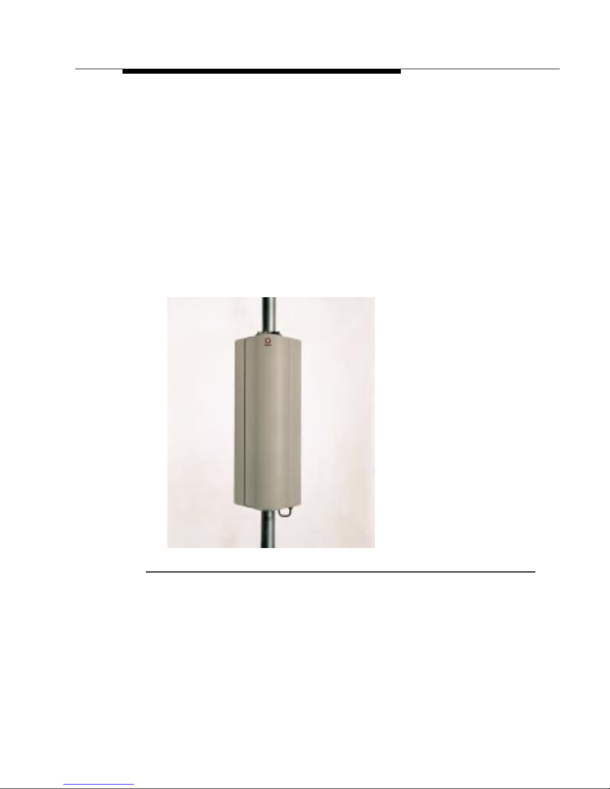
■ WaveACCESS NET CU232: A wireless point-to-multipoint
central unit that can support up to 60 remote units at a data
rate of 3.2 Mbps each. Using unique RFStacker™ technology,
up to ten WaveACCE SS NET CU232 units can be collocated
in a single site, creating a cell of up to 600 remote units at a
data rate of up to 25 Mbps. A remote unit does not necessarily
indicate a single user (for example, an MDR232 can support
an entire LAN). Therefore, the actual number of users the
WaveACCESS NET CU232 is able to support is considerably
higher than the number of remote units.
Figure 1-1 WaveACCESS NET CU 232
WaveACCESS NET 2400 Installation Guide 1-3
Page 5
Introducing the WaveACCESS NET 2400
System
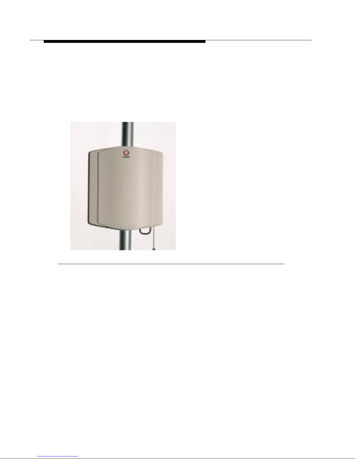
■ WaveACCESS NET SDR232: A standalone wireless LAN
adapter (remote unit), including a built-in antenna, designed to
connect to any computer’s Ethernet adapter card and allow
fast linking of any workstation to the Internet or Intranet. This
allows the user access to the full bandwidth, without having to
share the capacity with multiple users on a network.
Figure 1-2 WaveACCESS NET xDR232
■ WaveACCESS NET MDR232: A multidrop remote unit,
including a built-in antenna, that provides a bridging function
and enables a complete LAN to be connected over a wireless
network. This unit has particular application for a small office
environment, in which a single MDR232 would enable all the
computers to access the Internet.
1-4 WaveACCESS NET 2400 Installation Guide
Page 6
Introducing the WaveACCESS NET 2400
System
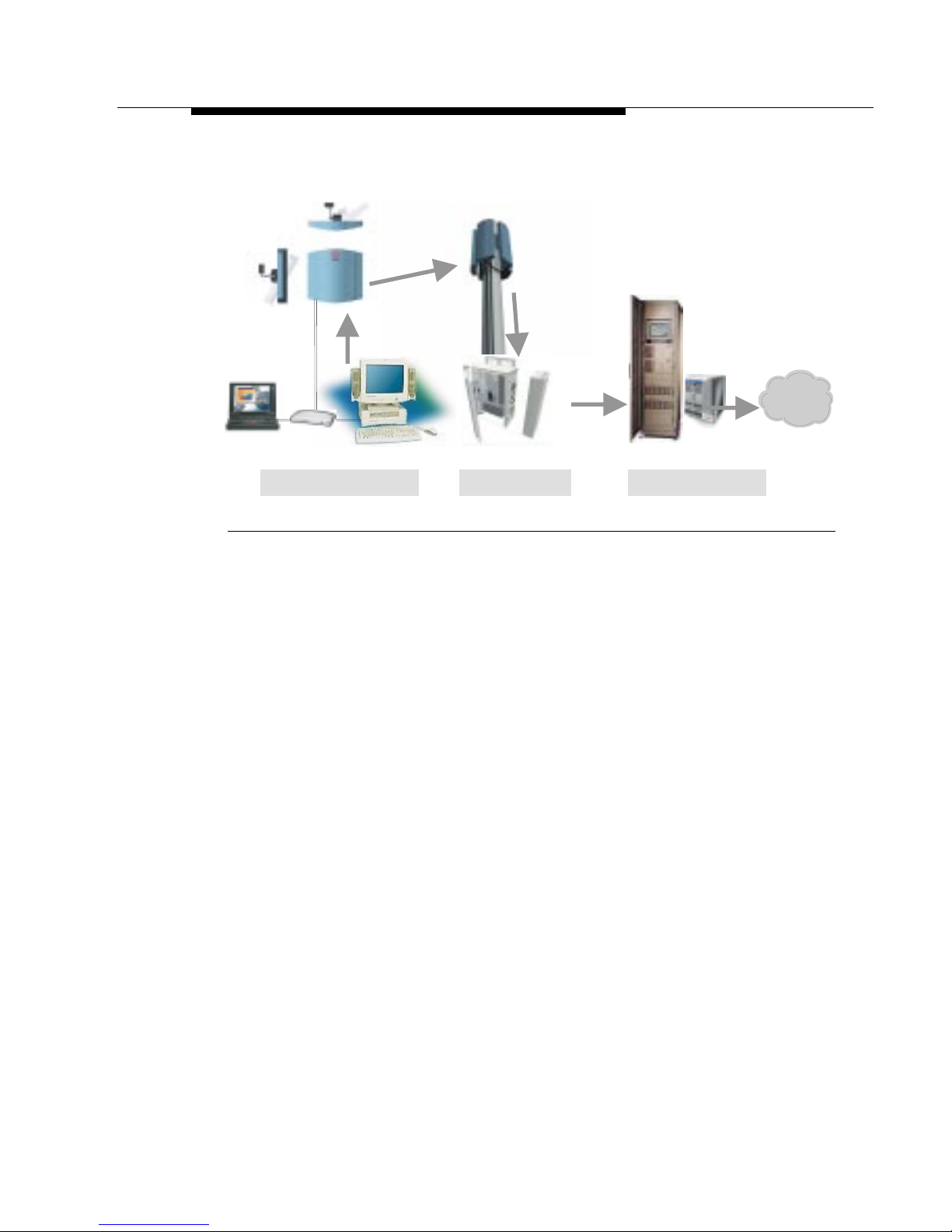
A high-level view of the system architecture is shown in Figure 1-3.
Air Interfa ce
Frame Relay
T1/E1
Customer Premises Base Station Switching Center
Internet
Figure 1-3 High Level System Architecture
Sectorization of the Central Site 1
WaveA CCESS NET CU232 units are typically installed in business
or residential areas which do not have well-defined boundaries. It
is not always possible to place the base station, with the central
units and antennas, in the optimal location. Therefore, the
WaveACCESS NET system provides the ability to sectorize the
base station by using multiple CU232 units, each o f which co v ers a
sector of the total area to be covered.
This allows an increase in cell range from approximately two miles,
for an omnidirectional 8dBi antenna, to approximately seven miles
for a 20dBi panel antenna.
If you have many users in one area, you may have more than one
CU232 covering the same area to provide optimal throughput for
all the users.
WaveACCESS NET 2400 Installation Guide 1-5
Page 7

Introducing the WaveACCESS NET 2400
System
Features and Benefits 1
The WaveACCESS NET wireless point-to-multipoint system has
numerous features and benefits that can enhance working
environments where wireless systems are essential:
■ Simple deployment, installation and operation.
■ Digital Frequency Hopping Spread Spectrum (FHSS)
technology that can support many overlapping links and
deliver resilience to interference and exceptional data integrity.
■ Operates in the 2.4 GHz ISM band, making it available for
unlicensed use in most parts of the world.
■ No configuration requirements, just plug it in and it works.
■ Management and configuration utilities enable you to quickly
make advanced configuration changes.
■ Fully digital packet radio with advanced QPSK and 16QAM
modulation.
■ Advanced bandwidth-enhancing ADEQ™ technology.
■ Optional dual antenna diversity.
■ SNMP managed, MIB II compliant with proprietary MIB.
■ Long range, high speed point-to-multipoint links.
■ Bandwidth management on a per-link basis.
■ Improved security features for ISPs.
1-6 WaveACCESS NET 2400 Installation Guide
Page 8

Introducing the WaveACCESS NET 2400
System
WaveACCESS NET Ruggedized Unit 1
The WaveACCESS NET 2400 units are fully ruggedized and
suitable for outdoor installation, in weather conditions of -40°C to
55°C.
An internal antenna is embedded in each unit, although there is
also an option to use an external antenna for wider coverage. A
single flexible cable is used to transmit data and supply the unit’s
power. The WaveACCESS NET 2400 product now includes a
power/data adapter that connects to the AC power supply directly
and provides an Ethernet connection.
While th e W aveACCESS NET 2400 system is fully compatible with
the previous WaveACCESS NET version, it provides enhanced
functionality, as follows:
■ Firstly, the fact that the unit is ruggedized and has an
embedded antenna precludes the need for a long RF cable
connecting the indoor unit to its external antenna (with its
inevitable losses). Thus, the signal quality and the effective
ranges are improved.
Increased maximum range enables ISPs to accommodate
more users with a higher data rate in that cell and at the same
level of service. This benefits both ISPs and users of the
system, as users with a low data rate use more bandwidth
when transmitting the same data, than users with a higher data
rate.
■ Secondly, the WaveACCESS NET 2400 units custom cable
connects to both the AC power supply and the Ethernet via a
single box, as opposed to the two boxes (one each for power
supply and Ethernet) in the previous version. The cable itself is
thin and easy to manipulate and enables the unit to be placed
up to 100 meters from the power supply.
■ Thirdly, the WaveACCESS NET 2400 is easier to install.
WaveACCESS NET 2400 Installation Guide 1-7
Page 9
Introducing the WaveACCESS NET 2400
System
You have the option to set up an external antenna for wider
coverage than is provided by the internal directional antenna.
When an external antenna is used, it is connected directly to the
radio output.
Technical Specifications 1
The following technical specifications for the WaveACCESS NET
units are for reference purposes only. The actual product’s
performance and compliance with local regulations may vary from
country to country. Lucent Technologies reserves the right to
improve the products from time to time and actual specifications
may vary.
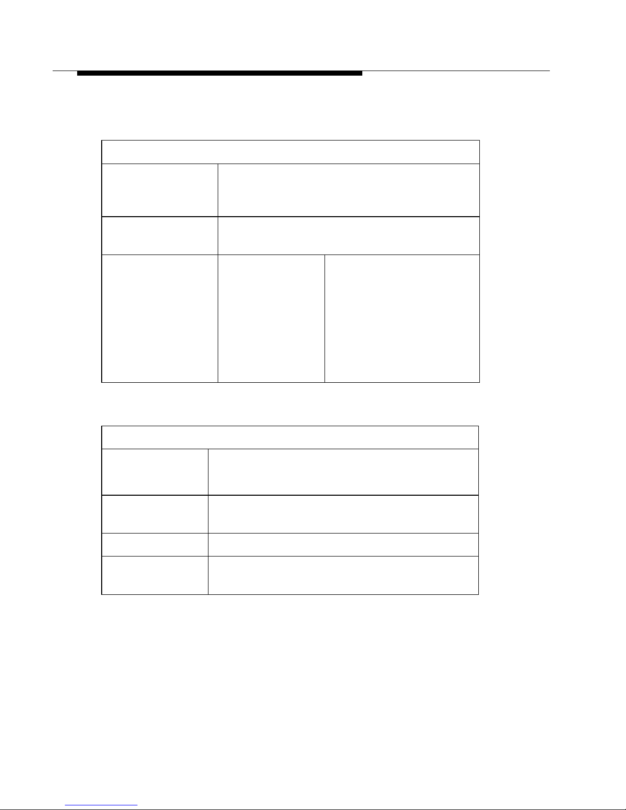
Table 1-1 Technical Specifications of the WaveACCESS NET Unit
MODELS: WaveACCESS NET CU232, MDR232, and SDR232
Description CU232
2.4 GHz Wi reless
point-to-multipoint
Ethernet Bridge
Central Unit
Wireless
Medium
Operating
Frequency
Frequency Hopping Spread Spectrum (FHSS)
2.402 - 2.480 GHz
MDR232 AND SDR232
2.4 GHz Wi reless
point-to-mulitpoint
Ethernet Bridge
1-8 WaveACCESS NET 2400 Installation Guide
Page 10

Introducing the WaveACCESS NET 2400
System
Table 1-2 WaveACCE SS NET Unit Performance Specifications
PERFORMANCE
Data Rate CU232
3.2 Mbps, fal lba ck
to 1.6 Mbps
No. of Ind.
Channels
Cell
Throughput
Throughput
Enhancement
TECHNICAL DAT A
Radio
Technology
Antenna
Connector
79
CU232
Up to 2.2 Mbps @
3.2 Mbps
1.2 Mbps @
1.6 Mbps
ADEQ™ Adaptive Equalization
FHSS using QPSK and QAM modulati on
Reversed polarity SMA
MDR232 AND SDR232
3.2 Mbps, fallback to 1.6
Mbps
MDR232 AND SDR232
Up to 2.2 Mbps @ 3.2 Mbps
1.2 Mbps @ 1.6 Mpbs
Antenna
Diversity
Output Power 50 mW
Wired LAN
Connections
Wired LAN
Protocol
Option for 2 separate antennas
10Base-T (RJ-45)
IEEE 802.3 CSMA / CD
WaveACCESS NET 2400 Installation Guide 1-9
Page 11
Introducing the WaveACCESS NET 2400
System
Table 1-3 WaveACCESS NET Unit Configuration and
Management Specifications
CONFIGURATION AND MANAGEMENT
Configuration Via any wired Ethernet LAN station, SNMP,
TFTP, Bootp, or via RS-232 9-pin female
D-type connecto r.
SNMP
Management
LED Indicators CU232
MIB II, Bridge MIB and proprietary MIB
MDR232 AND SDR232
Power, System
Status, Wired
Ethernet Link,
Wired Ethernet
Transmit,
Wireless
Transmit, Sync.
Power, System Status,
Wired Ethernet Link,
Wired Ethernet Transmit,
Wireless Transmit, Sync.
Table 1-4 WaveACCESS NET Unit Environmental Specifications
ENVIRONMENTAL
Dimensions 8 x 1.5 x 4.25 in
(20.5 x 3.8 x 10.8 cm)
Temperature
Range
32°F to 105°F (0°C to 40°C)
Humidity 0% to 95% non-condensing
External Power
Supply
1-10 WaveACCESS NET 2400 Installation Guide
110 VAC or 220 VAC,
50/60 Hz, 6.2 VDC @ 1.5 A
Page 12
Introducing the WaveACCESS NET 2400
System
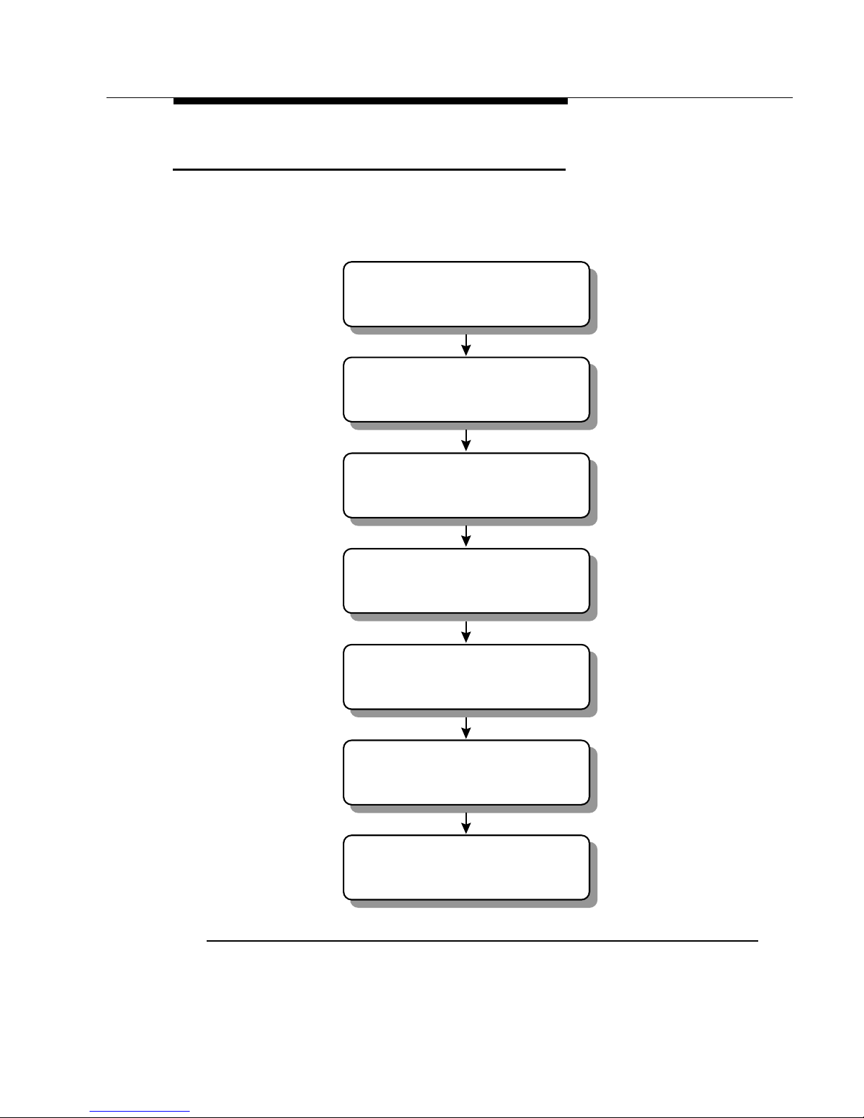
CU232 Installation Workflow 1
The following workflow illustrates the procedure that may be
followed when installing the CU232.
Fasten the mounting bracket
to the support
Attach the CU232 to the
mounting bracket
Adjust the direction a nd
downtilt of the CU232
Tighten the CU232 attachment
to the mounting bracket
Connect the power/data
cable to the CU232
Connect the power/data cable
to the data/power adapter
Connect the power/data adapter
to the PC or LAN
Figure 1-4 CU232 I nstallation Workflow
WaveACCESS NET 2400 Installation Guide 1-11
Page 13
Introducing the WaveACCESS NET 2400
System
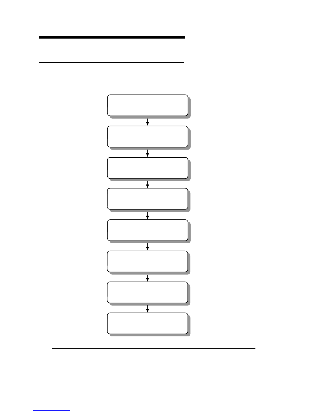
Remote Unit Installation Workflow 1
The following workflow describes the procedure that may be
followed when installing the xDR232.
Identify the xDR232 site and
prospective (intended) base station
Identify the optimal xDR232
mounting location
Install the mounting hardware
and attach the xDR232
Point the unit in the direction
of the base stat ion
Connect the po wer/data cable
between the xDR232 and adapter
Connect the power/data adapter
to the PC or LAN
Power up the xDR232
Align and fasten the xDR232
Figure 1-5 xDR232 Installation Workflow
1-12 WaveACCESS NET 2400 Installation Guide
Page 14

W a veA CCESS NET 2400 Base
Station Site Preparation
2
THIS IS AN INCOMPLETE DRAFT.
This chapter describes the requirements and specifications that
must be satisfied when preparing a site for the installation of the
WaveACCESS NET CU232 units (base station).
About this chapter: 2
Clearances and Space Requirements, page 2-2, describes the
clearances and space requirements for installing the CU232.
Tower Pipe Installation, page 2-6, describes
Electrical Power Requirements, page 2-7, provides guidelines
for the installation of electrical power to the base station.
Grounding and Lightning Protection Bonding Requirements,
page 2-8, describes the grounding and lightning protection
requirements for a WaveACCESS NET base station.
WaveACCESS NET 2400 Installation Guide 2-1
Page 15

WaveACCESS NET 2400 Base Station Site
g
Preparation
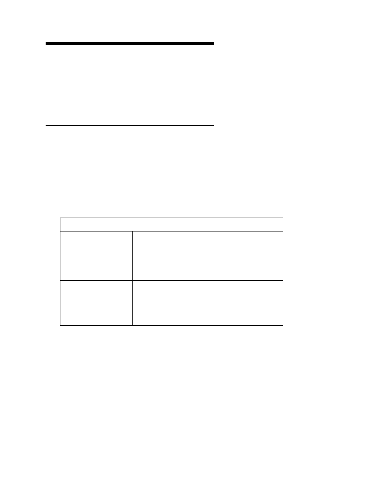
Clearances and Space
Requirements 2
The intended installat ion area must inclu de enou gh sp ace to
accommodate the CU232. Figure 2-1 shows the space required for
the CU232 installation.
21.2"
Groundin
Stud
25"
27.5"
3" Min
WALL
Figure 2-1 Space Required for CU232
UNOBSTRUCTED VIEW
o
40
o
45
MAX.
PIVOT
ANGLE
TOP VIEW
C
L
o
40
o
45
MAX.
PIVOT
ANGLE
Dimensions and Weight of the CU232 2
The dimensions and weight of the CU232 are displayed in
Table 2-1.
2-2 WaveACCESS NET 2400 Installation Guide
Page 16
WaveACCESS NET 2400 Base Station Site
Preparation
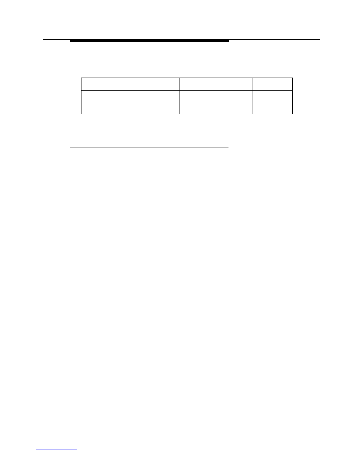
Table 2-1 Dimensions and Weight of the CU232 As-Installed
Equipment Width Depth Height Weight
CU232 12 in
30 cm
5 in
13 cm
30 in
76 cm
13 lbs
6 kg
Minimum Space Requir ed Betwee n Multiple
CU232s 2
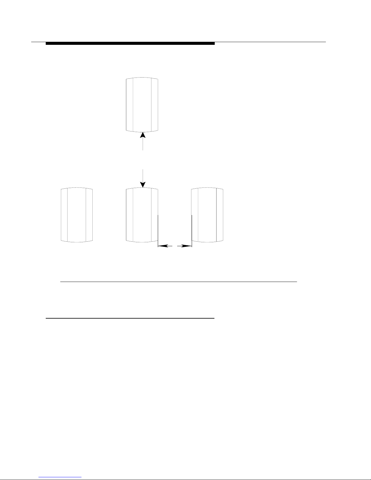
When multiple CU232s are installed, the space required between
each CU232 must be:
■ Horizontal space of 31 centimeters (12 inches).
■ Vertical space of 1 meter (3 feet).
WaveACCESS NET 2400 Installation Guide 2-3
Page 17
WaveACCESS NET 2400 Base Station Site
1/3 METER (Min.)
Preparation
Figure 2-2 shows the spacing requirements for multiple CU232s.
1 METER (Min.)
Figure 2-2 Multiple CU232 Spacing Requirements
CU232 Environmental Requirements 2
The environmental requirements must be within the limits specified
in Table 2-2, in order for the CU232 to operate properly.
2-4 WaveACCESS NET 2400 Installation Guide
Page 18

WaveACCESS NET 2400 Base Station Site
Preparation
Table 2-2 CU232 Environmental Requirements
Environmental Conditions
Minimum Ambient
Temperature
Maximum Ambient
Temperature
Minimum Relative
Humidity
Maximum Relative
Humidity
- 40.0 °C (- 40 °F)
+ 46.0 °C (+ 114.8 °F)
10%
100%
WaveACCESS NET 2400 Installation Guide 2-5
Page 19

WaveACCESS NET 2400 Base Station Site
Preparation
Tower Pipe Installation 2
It is recommended that towers have a wind rating of 100mph with
5, 10, or 15 CU232s. Each CU232 will experience 80 kg (175 lbs)
of wind load at 100mph w/wind factor normal to CU232. The tower
should be able to support 1, 2, or 3 sets of CU232s.
The installation height of the antenna must be approximately 15 m
above the surrounding average building height, or as specified by
the field RF engineer.
The pipes to which the CU232s will be attached should be
mounted either on a tower, or on the sides of a building near the
roofline, at a height specified by the field RF engineer.
When tower installation is performed, the pipe should be installed
around the tower with an angular separation of 72 degrees. In
certain instances, it may not be possible to install the support pipe
at 72 degree intervals. The ability to swing the CU232 from side to
side over an arc of approximately 45 degrees is required. One of
the support pipes should be mounted on the tower so that it faces
North. A subsequent pipe can then be installed at 72 degree
increments from the reference Northward facing pipe.
When performing the installation of five CU232s on a building, the
support pipes should be located on a common wall. The other
three CU232s can be installed on the other three sides of the
building. The clearance requirements should comply with
Figure 2-1.
The minimum distance between any CU232 support pipe and
other wireless telecommunication equipment should be
two meters.
2-6 WaveACCESS NET 2400 Installation Guide
Page 20

WaveACCESS NET 2400 Base Station Site
Preparation
Electrical Power Requirements 2
This section provides guidelines for the installation of AC or 48VDC
electrical power to the base station, as follows:
■ General Requirements, page 2-7.
■ CU232 Power Requirements, page 2-7.
General Requirements 2
All the AC wiring and over-current protection must be provided in
accordance with the National Electric Code (NFPA-70) and local
electrical codes. An appropriate earth-ground connection is
required before the commercial AC service can be connected. The
base station AC input power is single phase, nominal 120/208 or
120/240 Vrms, 50/60 Hz. Nominal voltage is defined as 120 Vrms
between line(s) to ground, and 208 Vrms or 240 Vrms line to line.
CU232 Power Requirements 2
Each CU232 requires 24-48VDC, 15 Watts, which is supplied by
the power/data adapter.
WaveACCESS NET 2400 Installation Guide 2-7
Page 21

WaveACCESS NET 2400 Base Station Site
Preparation
Grounding and Lightning
Protection Bonding Requirements 2
This section provides information on grounding and lightning
protection requirements for a WaveACCESS NET base st ati on , a s
follows:
■ General Requirements, page 2-7.
■ Lightning Protection, page 2-10.
General Requirements 2
The WaveACCESS NET base stations are susceptible to lightning
surges due to their association with towers and antennas.
Therefore, it is imperative that all base station components be
properly grounded, providing a low impedance path to earth. The
grounding conductors must be as straight and short as possible
and should not have any sharp bends or loops.
The CU232 cable shield must be bonded at the top and bottom of
the vertical run, and where it comes near the equipment. The tower
or metallic support of the antenna must also be bonded to the
grounding system. In addition, the surge protection device must be
bonded to a nearby ground bus bar that is connected directly to the
grounding electrode system.
All metallic objects within 2 meters (6 feet) of the grounded
equipment must be bonded to the grounding system.
All base station equipment must be bonded to a grounding
electrode system, for example, buried ring ground, copper clad
rod, electrolytic rods, metallic water pipe, and so on.
2-8 WaveACCESS NET 2400 Installation Guide
Page 22

WaveACCESS NET 2400 Base Station Site
Preparation
The minimum requirement for buried ground conductors is
#2 AWG bare, solid, tinned copper wire. Exterior ground
conductors must be either solid, bare, tinned copper or stranded,
insulated (for sunlight resistance) copper cable. The interior ground
cable must be stranded copper with green insulation type THAWN
or equivalent.
All grounding system material, namely, cable, connectors, buses,
and so on, must be made of high quality materials that are
resistant to deterioration and that require little or no maintenance.
An exothermic weld is recommended for grounding connections,
where practical. All below-grade connections must be
exothermically welded. In addition, compression type, long barrel,
two-hole (0.75" center) lugs or double crimp “C” Taps are also
acceptable. The metal contacts to which connections are made
must have a bare bright finish, and be coated with an anti-oxidation
material.
Refer to Lucent Technologies 401-200-115,
Grounding and
Lightning Protection Guidelines for Wireless System Base
Stations
lightning protection bonding.
!
, for detailed requirements regarding grounding and
WARNING:
The equipment warranty can be voided if the guidelines
detailed in the National Electric Code (NFP A 70), Standard
for Installation of Lightning Protection System (NFPA 780,
1995 edition), Lucent Technologies 401-200-115, and
Lucent Technologies Equipment Drawings referred to in
this document are not followed.
Refer to Appendix C for a checklist of the verification of the
grounding requirements that can be performed.
WaveACCESS NET 2400 Installation Guide 2-9
Page 23

WaveACCESS NET 2400 Base Station Site
Preparation
Lightning Protection 2
The preferred method of reducing the risk of lightning strikes is
avoidance. CU232s and remote units must be mounted within the
o
lightning protection cones, as shown in Figure 2-3. The 45o
45
lightning protection cone also applies to tower-mounted units.
Cone of Protection
o
45
o
45
o
45
Cone of Pr otection
o
45
o
45
Figure 2-3 Lighting Protection Cone
A
B
2-10 WaveACCESS NET 2400 Installation Guide
Page 24

Installing the CU232
3
THIS IS AN INCOMPLETE DRAFT.
This chapter describes the installation procedures of the
WaveACCESS NET CU232.
About this chapter: 3
Installation Requirements for the CU232, page 3-2 describe s
the physical installation requirements of the WaveACCESS NET
CU232.
Mounting and Tilting the CU232, page 3-5 describes the
procedure for mounting and tilting the WaveACCESS NET CU232.
Connecting the Power/Data Cable, page 3-8 describes the
procedure for connecting the power/data cable to the
WaveACCESS NET CU232.
Connecting the Po wer/Data Cable to the Adapter, page 3-9
describes the procedure for connecting the power/data cable to the
power/data adapter.
Connecting to the PC or LAN, page 3-9 describes connecting the
CU232 to your computer or network by installing the power/data
cable between the CU232 and the power/data adapter.
Po wering Up the CU232, page 3-9 describes the procedure for
powering up the CU232.
WaveACCESS NET 2400 Installation Guide 3-1
Page 25

Installing the CU232
Installation Requirements for
the CU232 3
The qualifications required for an installer are similar to those
required to install standard office telecommunications equipment.
Installers should be familiar with local construction techniques,
requirements, and regulations associated with the installation of
cabling and brackets in an urban or suburban environment, and
must be able to run simple diagnostic procedures.
This section describes the physical installation requirements of the
WaveACCESS NET CU232, as follows:
■ Installation Items Provided by Lucent, page 3-2.
■ Additional Installation Items Required, page 3-3.
Installation Items Provided by Lucent 3
The following items are included in the Lucent Technologies
installation ki t:
■ WaveACCESS NET CU232 wireless central unit.
■ CU232 mounting bracket.
■ One power/data adapter complete with a 5-foot (1.5m) cord.
■ A software diskette.
■ One power/data cable of 10m, 30m, or 100m.
■ This WaveACCESS NET 2400
■ A CD-ROM containing documentation.
When an additional antenna is required, you will also receive a
second package that includes the WaveACCESS NET antenna kit
that was ordered with the system.
Installation Guide
.
3-2 WaveACCESS NET 2400 Installation Guide
Page 26

Installing the CU232
NOTE:
If any of these items are incomplete or missing, you might
not be able to install the WaveACCESS NET CU232. In
this case please contact your nearest Technical Support
Center. Refer to Chapter 8 ”Technical Support” for more
information.
The following additional items are provided by Lucent T echnologies
for the installation team:
■ Cable tester (comcode #).
■ Power/data cable (comcode 408158830).
■ CU232 electr i cal power tester (co mcode #).
Additional Installation Items Required 3
The following list describes the items that are not provided by
Lucent Technologies, but are required for installation.
■ Bolts, mounting hardware
■ Drill and drill bits
■ Grounding braid
■ Nut drivers
■ Ladder
■ Pliers
■ Long nose pliers
■ Screwdrivers
■ Safety glasses
■ Cable ties
WaveACCESS NET 2400 Installation Guide 3-3
Page 27

Installing the CU232
■ Specialized wire stripping tools:
■ Precision wire stripper
OK Industries, model ST-550
Details from www.okindustries.com
Available from: Newark Electronics, Tel. 800-463-9275
■ Cable jacket cutter
Ideal Cyclops, model 45-514
■ Data cable cutter
Ideal Cyclops, model 45-074
Details from www.idealindustries.com
■ Miniature needle nose pli ers
■ Phillips No. 1 screwdriver
■ Flat screwdriver with 2.3 to 2.5 mm blade
Available from: Allied Electronics, Tel. 800-433-5700
■ Wrenches
■ Torque wrench (40 in-lb capacity)
■ Multimeter
■ Cutters
■ Downtilt meter
■ Utility knife
■ Tape measure
■ Pipe, U-bolts, and so on.
■ Connections to Ethernet
■ Compass or other directional equipment
3-4 WaveACCESS NET 2400 Installation Guide
Page 28

Installing the CU232
Mounting and Tilting the CU232 3
The WaveACCESS NET CU232 should be mounted in front of a
wall or structure, to minimize the interference of other signals from
behind the unit.
The CU232 mounting bracket can be fastened in the following
ways:
■ To a 2 m (6 ft.) long, 5 cm (2 in) diameter “schedule 40” pole,
using two of the tension belts provided along with the mating
nuts and split lock washers (preferred technique).
■ To a pole that is rigidly fastened to a tower (optional
technique).
The location of the CU232 bracket supports will be provided by the
site preparation team, in compliance with the site preparation
guidelines, as described in Chapter 2.
Prior to installation, record or scan the barcode that includes the
serial number and MAC addresses of the CU232s, and identify the
azimuth (horizontal) and elevation (downtilt) in which each CU232
will be pointing when installed. Provide the orientation information
to the RF network planner.
WaveACCESS NET 2400 Installation Guide 3-5
Page 29
Installing the CU232
To mount the CU232: 3
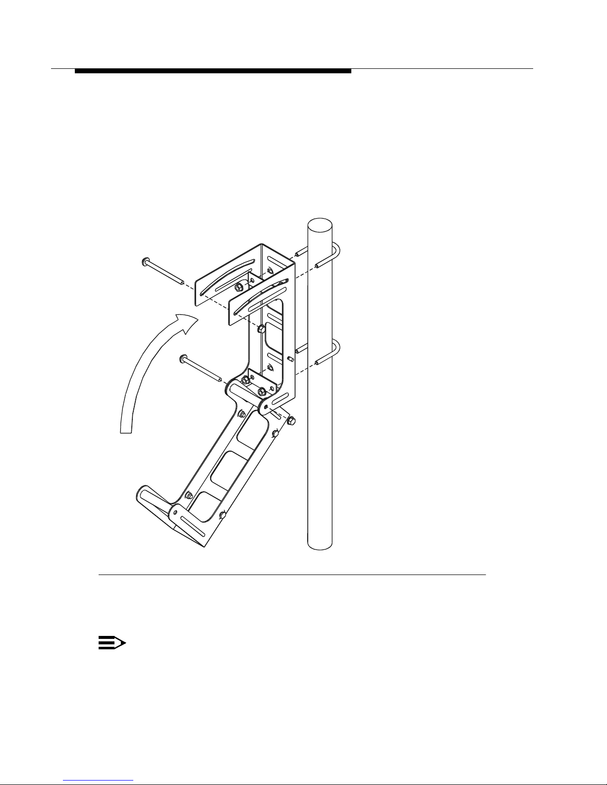
1. Fasten the CU232 mounting bracket to the pole with the two
straps. You can improve the access to the fastening hardware
by opening the CU232 mounting to the "unfolded"
configuration, as shown in Figure 3-1. The mounting bracket
should face in the general direction of the remote unit.
Figure 3-1 CU232 Mounting Bracket Fastened to Pole
2. Mount and partially fasten the CU232 to the bracket.
NOTE:
Ensure that you perform steps 3 and 4 before tightening
the straps completely.
3-6 WaveACCESS NET 2400 Installation Guide
Page 30
Installing the CU232
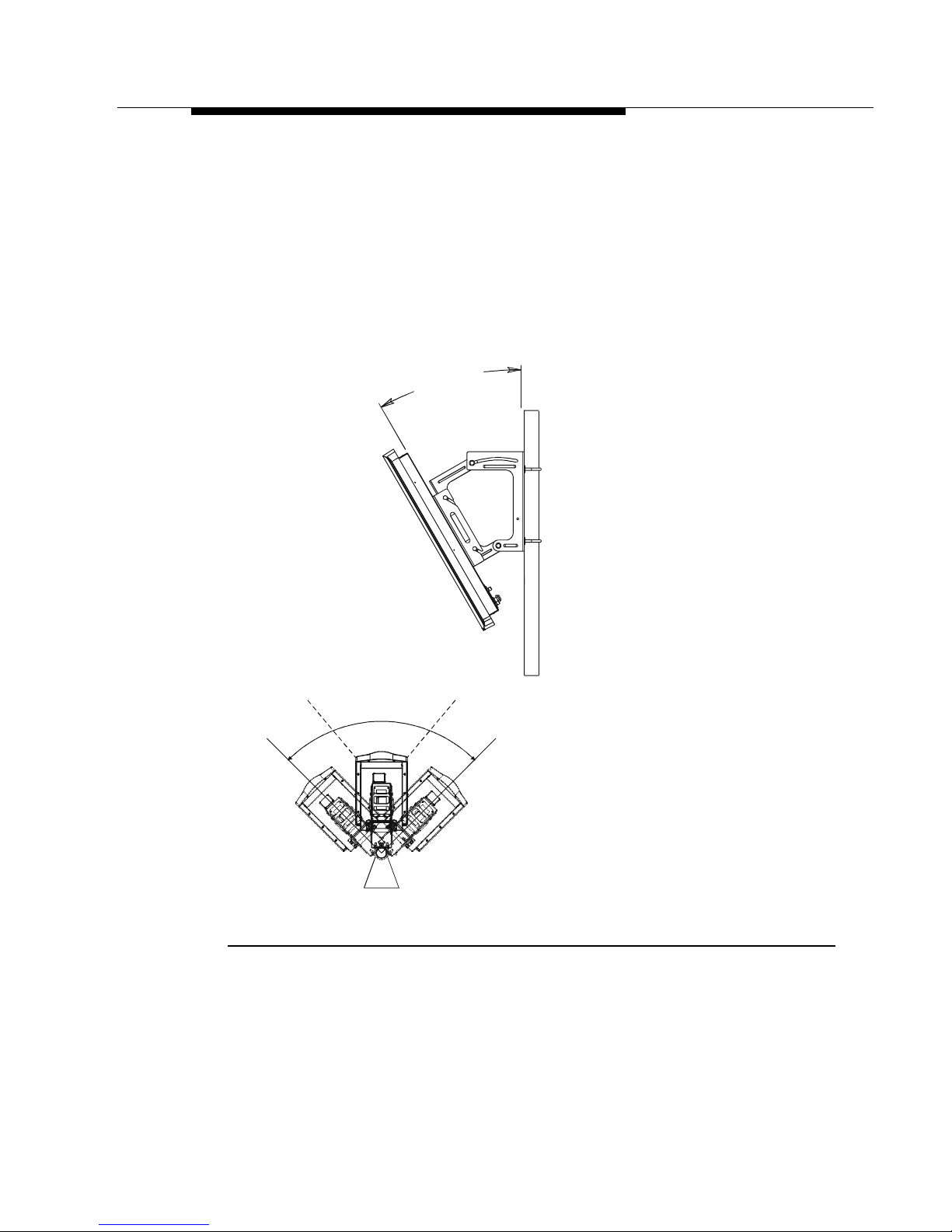
3. Adjust the direction of the CU232 by rotating it to the required
azimuth (horizontal) orientation.
4. Using the downtilt meter adjust the downtilt of the CU232
according to the RF planning requirements for the site.
5. Tighten the fastening belts of the CU232 when it is correctly
oriented.
6. Tighten the pivot bolts.
DOWNTILT ANGLE
ADJUST PIVOT ANGLE
TOP VIEW
Figure 3-2 CU232 Tilt Angle
WaveACCESS NET 2400 Installation Guide 3-7
Page 31

Installing the CU232
Connecting the Power/Data Cable 3
When you have completed mounting and tilting the CU232, it must
be connected to the power/data cable.
NOTE:
It is recommended that you use the Lucent cable tester
(comcode #) with the adapter cable (comcode 848340337)
to verify the power/data cable integrity before plugging the
cable into the CU232. Before you make the connections to
the CU232, check that the wiring is correct.
To connect the power/data cable: 3
1. Connect the power/data cable to the water-tight connector on
the cover plate. Turn the connector until it clicks.
2. Label the power/data cable according to the CU232 to whic h i t
is connected, namely, CU232#1, CU232#2, and so on.
3. It is recommended that the power/data cable be clamped at
regular intervals. Ensure that you leave extra cable at the
CU232 in case further maintenance and adjustments are
required.
3-8 WaveACCESS NET 2400 Installation Guide
Page 32

Installing the CU232
Connecting the Power/Data Cable
to the Adapter 3
This step involves connecting the CU232 to your computer or
network by installing the power/data cable between the CU232 and
the power/data adapter. Figure 3-3 provides a guide to wiring the
power/data adapter.
Cable Connection To Interface Adapter Box.
DC Connector
RJ45 jack
Pin 1
Pin 8
Black
R
+
+
R
1
2
3
6
Red
White/Orange
Orange
White/Blue
Blue
DC Return 18awg
DC Positive 18awg
Data 24awg
Data 24awg
Data 24awg
Data 24awg
Figure 3-3 Cable Connection to the Power/Data Adapter
!
CAUTION:
The CU232 must be grounded to prevent an atmospheric
static charge from accumulating on the chassis and to
reduce unpredictable static discharges that may result in
serious damage to the subscriber’s equipment (Ethernet
hubs, PCs, LANs, and so on), as well as to the remote unit.
WaveACCESS NET 2400 Installation Guide 3-9
Page 33

Installing the CU232
!
CAUTION:
When installing CU232
s,
follow the guidelines detailed in
the National Electric Code (NFPA 70), Standard for
Installation of Lightning Protection System (NFPA 780,
1995 edition), Lucent Technologies 401-200-115, and the
Lucent Technologies Equipment Drawings referred to in
this document.
To connect the power/data cable to the power/data adapter: 3
1. Using the Cyclops cable jacket cutter (Model 45-514), strip the
outer sheath 22 to 28 mm and remove the sheath, foil shield
and the bare wire.
2. Untwist the pairs of wires. Set the strip length of the precision
wire stripper (OK Industries Model ST-550) to 6mm and set the
dial to 10. Strip the red and black wires.
3. Reset the precision wire stripper dial to 5 and strip the
remaining 4 wires.
4. Push all 6 levers down.
5. Holding the power/data adapter in one hand, use the needle
nose pliers to locate the red and black wires in the correct
color-coded terminals of the terminal block and push the levers
back to secure the wires.
6. Locate the orange pair of wires and tighten them. Locate and
tighten the blue pair of wires.
7. Push the cable towards the terminal block so that the cable
clamp grips onto the outer sheath. Pull the clamp tight with the
needle nose pliers.
8. Check that the clamp is secure by slowly pulling the cable.
9. Locate the printed wiring board in the adapter. Put on the cover
and tighten the screw with a No. 1 Phillips screwdriver.
3-10 WaveACCESS NET 2400 Installation Guide
Page 34

Installing the CU232
Figure 3-4 provides a guide to connecting the power/data
adapter.
Wire wrap
Figure 3-4 Connecting the Power/Data Adapter
WaveACCESS NET 2400 Installation Guide 3-11
Page 35

Installing the CU232
Connecting to the PC or LAN 3
This step involves connecting the CU232 to your PC or network
using an Ethernet cable.
1. Connect the Ethernet cable from the power/data adapter to a
PC using a "cross-over" cable format for single user
installations, as shown in Figure 3-5.
WM
1
0
0
M
E
T
E
R
(
M
S
A
X
.
)
IAB
"
S
S
O
T
R
-
C
e
"
s
a
B
E
0
L
1
B
A
C
Figure 3-5 Single User Installation Connecting the Ethernet Cable
3-12 WaveACCESS NET 2400 Installation Guide
Page 36

Installing the CU232
L
Alternatively, use a "straight-through" cable format when
connecting the power/data adapter to a LAN hub for multiple
user installations, as shown in Figure 3-6.
WM
OPTIONAL
ETHERNET
HUB
IAB
1
0
0
M
E
(
M
T
E
AX
R
S
.
)
AC
STRAIGHT
10Base-T CAB LE
A C to DC
CONVERTER
TO
ADDITIONA
PCs
Figure 3-6 Multiple User Installation Connecting the Ethernet
Cable
WaveACCESS NET 2400 Installation Guide 3-13
Page 37

Installing the CU232
Powering Up the CU232 3
After they have been connected, the WaveACCESS NET CU232
units can be powered up.
To power up the CU232: 3
■ Plug the power supply into an AC outlet. The power supply is
doubly insulated and therefore a ground outlet is not required.
NOTE:
When you are turning off the power to the CU232, wait at
least 10 seconds for the capacitors in the CU232 to
discharge before reapplying power . If the capacitors do not
discharge, the CU232 will not initialize properly.
Lightening Protection 3
For information, refer to Appendix A “Lightening Protection”.
3-14 WaveACCESS NET 2400 Installation Guide
Page 38

WaveACCESS NET 2400
Remote Unit Site Preparation
4
THIS IS AN INCOMPLETE DRAFT.
This chapter describes the requirements and specifications that
must be satisfied when preparing a site for the installation of the
WaveACCESS NET remote units (MDR232 and SDR232).
About this chapter: 4
Overview, page 4-2, describes the WaveACCESS NET remote
units.
Horizontal Surface Mounting, page 4-3, describes mounting the
WaveACCESS NET xDR232 on a horizontal surface.
Vertical Surface Mounting, page 4-6, describes mounting the
WaveACCESS NET xDR232 on a vertical surface.
Remote Unit (xDR232) Environmental Requirements,
page 4-8, describes the environmental requirements of the
WaveACCESS NET remote units.
Remote Unit (xDR232) Wiring, page 4-9, describes the wiring
requir ements of the WaveACCESS NET remote units.
WaveACCESS NET 2400 Installation Guide 4-1
Page 39

WaveACCESS NET 2400 Remote Unit Site
Preparation
Overview 4
The remote units (xDR232s) are the user locations, where remote
WaveACCESS NET units act as LAN adapters. There are two
types of remote units, each of which includes a built-in antenna
and interfaces to end user PCs:
■ MDR232: A multidrop remote that provides a bridging function
and enables a complete LAN to be connected over a wireless
network. This unit has a particular application for a small office
environment, in which a single MDR232 would enable all the
computers to access the Internet.
■ SDR232: A single drop remote that enables single user access
to the Internet. This allows the user access to the full
bandwidth, without having to share the capacity with multiple
users on a network.
The xDR232 provides a reliable air interface capability to the
subscriber. It connects to the end user via a 10Base-T physical
interface supporting the Ethernet protocol. The xDR232 is
physically attached to the outside of a home or office. It measures
34 cm x 31 cm x 13 cm and weighs 4 kgs.
The xDR232 package consists of the following:
■ xDR232 unit.
■ P ower/data adapter .
■ Data and power cables.
■ P ower supply.
■ Mounting brackets (vertical/horizontal).
4-2 WaveACCESS NET 2400 Installation Guide
Page 40

WaveACCESS NET 2400 Remote Unit Site
Preparation
Horizontal Surface Mounting 4
This section describes mounting the WaveA CCESS NET MDR232
and SDR232 on a horizontal surface, as follows:
■ Physical Considerations, page 4-3.
■ Clearances, page 4-4.
■ Dimensions and Weight of the xDR232, page 4-5.
■ Cabling and Facilities Requirements (Customer-Supplied),
page 4-5.
Physical Considerations 4
When preparing the remote site for horizontal surface mounting,
the structure needs to conform with the basic space and
environmental requirements. The specified area must include the
space required by the xDR232, as shown in Figure 4-1.
WaveACCESS NET 2400 Installation Guide 4-3
Page 41

WaveACCESS NET 2400 Remote Unit Site
Preparation
Clearances 4
A sufficient amount of space must be provided so that the xDR232
can swing up and down, and side to side. The minimum spacing
requirements for the xDR232 is a height of 43 cm (17 in) and a
width of 31 cm (12 in).
12 in
14 in
17 in
To
Ground
Figure 4-1 Horizontal Surface Mounting Space Requirements for
the xDR232
4-4 WaveACCESS NET 2400 Installation Guide
Page 42

WaveACCESS NET 2400 Remote Unit Site
Preparation
Dimensions and Weight of the xDR232 4
The dimensions and weight of the xDR232 are displayed in
Table 4-1.
Table 4-1 xDR232 As-Installed Dimensions and Weight
Width Depth Height Weight
12 in
31 cm
4 in
9 cm
17 in
43 cm
8 lbs
4 kg
Cabling and Facilities Requirements
(Customer-Supplied) 4
A typical horizontal surface mounting site should have all the
required grounding completed before beginning the installation of
the xDR232.
WaveACCESS NET 2400 Installation Guide 4-5
Page 43

WaveACCESS NET 2400 Remote Unit Site
Preparation
Vertical Surface Mounting 4
This section describes mounting the WaveACCESS NET xDR232
on a vertical surface, as follows:
■ Physical Considerations, page 4-6.
■ Clearances, page 4-6.
Physical Considerations 4
When you are preparing the xDR232 site for vertical surface
mounting, the structure needs to conform with the basic space and
environmental requirements. The specified area must include the
space required by the xDR232, and the mounting pipe (optional).
Although the mounting pipe is optional, it is highly recommended
that one is used.
When selecting the site for the xDR232, keep in mind that the
maximum cable length allowed from the xDR232 to the PC/
Ethernet Hub connector is 100 m (300 ft.), as shown in Figure 4-3.
Clearances 4
The spacing requirements for the xDR232 are critical. It is
essential that enough clearance is provided so that the xDR232
can swing up and down, and side to side. A minimum clearance of
33 cm (13 in) is recommended for the xDR232 to swing up and
down, and 81 cm (32 in) to swing side to side.
When mounting the xDR232 with the optional pipe, there is an
additional spacing requirement of 15 cm (6 in) so that the xDR232
can swing in all directions.
4-6 WaveACCESS NET 2400 Installation Guide
Page 44

WaveACCESS NET 2400 Remote Unit Site
g
Preparation
The vertical surface mounting space requirements for the xDR232
are shown in Figure 4-2.
32"
Groundin
R
Stu d
13"
W
A
Figure 4-2 Vertical Surface Mounting Space Requirements
L
L
WaveACCESS NET 2400 Installation Guide 4-7
Page 45

WaveACCESS NET 2400 Remote Unit Site
Preparation
Remote Unit (xDR232) Environmental
Requirements 4
This section describes the WaveACCESS NET xDR232
environmental requiremen ts.
The environmental requirements must be within the limits specified
in Table 4-2 in order for the xDR232 to operate properly.
Table 4-2 Vertical Surface Mounting Environmental
Requirements
Environmental Conditions
Minimum Amb ien t
Temperature
Maximum Ambient
Temperature
Minimum Re la tiv e
Humidity
Maximum Relat ive
Humidity
- 40 °C
- 40 °F
46 °C
115 °F
10%
100%
4-8 WaveACCESS NET 2400 Installation Guide
Page 46

WaveACCESS NET 2400 Remote Unit Site
Preparation
Remote Unit (xDR232) Wiring 4
This section describes the WaveACCESS NET MDR232 and
SDR232 wiring requirements, as follows:
■ Cable Entry, page 4-9.
■ Site Grounding and Bonding Requirements, page 4-10.
Cable Entry 4
A point of entry is required to connect the xDR232 to the power/
data adapter, which is always located indoors, as shown in
Figure 4-3.
Remote
Unit
Ground
Distance from
xDR23 2 to PC
(or Ethernet Hub)
(100m Max)
To
Power/Data
Cable
Point of En try
WALL
INDOOR OUTDOOR
PC/Etherne t
Hub LAN
Power/Data
Adapter
Ethernet
Power
Converter
To
AC
Figure 4-3 xDR232 Wiring
WaveACCESS NET 2400 Installation Guide 4-9
Page 47

WaveACCESS NET 2400 Remote Unit Site
Preparation
Site Grounding and Bonding Requirements 4
The grounding system must provide a low-impedance path from
the xDR232 to the earth in order to protect personnel from electric
shocks and to ensure the safe, reliable operation of the equipment.
For more in fo rmation, refe r to
Base Station Site Preparation
Chapter 2, Wav eACCESS NET 2400
.
!
WARNING:
The equipment warranty can be voided if the guidelines
detailed in the National Electric Code (NFP A 70), Standard
for Installation of Lightning Protection System (NFPA 780,
1995 edition), Lucent Technologies 401-200-115, and
Lucent Technologies Equipment Drawings referred to in
this document are not followed.
4-10 WaveACCESS NET 2400 Installation Guide
Page 48

Installing the Remote Units
5
THIS IS AN INCOMPLETE DRAFT.
This chapter describes the installation procedures of the
WaveACCESS NET MDR232 and SDR232.
About this chapter: 5
Overview, page 5-2, provides a brief overview and installation
workflow for the remote units.
Safety Precautions, page 5-3, lists the safety precautions for the
NET service provider.
Installation Requirements for the xDR232, page 5-4, describes
the physical installation requirements for the WaveACCESS NET
xDR232.
Installing the xDR232, page 5-7, describes how to install the
xDR232.
Troubleshooting, page 5-25, provides a list of solutions for
xDR232 installation problems.
WaveACCESS NET 2400 Installation Guide 5-1
Page 49

Installing the Remote Units
Overview 5
This section describes the physical installation of the remote unit
(xDR232). The qualifications required for an installer are similar to
those required to install standard office telecommunications
equipment. Installers should be familiar with local construction
techniques, requirements, and regulations associated with the
installation of cabling and brackets in an urban or suburban
environment. The installation personnel must be able to run simple
diagnostic procedures.
NOTE:
The wiring described in this manual is only applicable
within the same building and may not be extended to other
structures.
A pipe-mounted xDR232 is shown in Figure 5-1.
Figure 5-1 Remote Unit (xDR232)
5-2 WaveACCESS NET 2400 Installation Guide
Page 50

Installing the Remote Units
Safety Precautions 5
The NET service provider must ensure that each of the following
requirements has been met:
■ The building or tower has been certified as safe to climb.
■ All exposed working areas have anchoring points or safety
lines.
■ All potential hazards have been identified, for example, fragile
roofs, dangerous materials or machinery , and so on. W alkwa ys
should have been identified and marked out.
■ Electrical installation work has been performed by trained and
certified personnel.
■ Safety devices have been inspected and certified.
■ Safety glasses must be worn during installation.
!
CAUTION:
The equipment installed must be properly grounded.
Failure to do this will inva lidate the product warranty.
WaveACCESS NET 2400 Installation Guide 5-3
Page 51

Installing the Remote Units
Installation Requirements for
the xDR232 5
This section describes the physical installation requirements of the
WaveACCESS NET MDR232 and SDR232, as follows:
■ Installation Items Provided by Lucent, page 5-4.
■ Additional Installation Items Required, page 5-5.
Installation Items Provided by Lucent 5
The following items are included in the Lucent Technologies
installation kit per xDR232:
■ Either a W a veA CCESS NET SDR232 single-drop remote, or a
WaveACCESS NET MDR232 multi-drop remote.
■ One power/data adapter complete with a 5-foot (1.5m) cord.
■ For the WaveACCESS NET SDR232 only, a 4-foot (1.2m)
10Base-T Ethernet crossover cable (optional).
■ A software diskette.
■ One power/data cable of 10m, 30m, or 100m.
■ This WaveACCESS NET 2400
■ CD-ROMs containing documentation and software drivers for
Installation Guide
.
end user PCs.
■ Mounting bracket.
■ AC cord.
When an additional antenna is required, you will receive a second
package that includes the WaveACCESS NET antenna kit that
was ordered with the system.
5-4 WaveACCESS NET 2400 Installation Guide
Page 52

Installing the Remote Units
NOTE:
If any of these items are incomplete or missing, you might
not be able to install the WaveACCESS NET SDR232 or
MDR232. In this case, please contact your nearest
Technical Support Center. Refer to
Support
for more information.
Chapter 8, Technical
The following is a list of the additional items available from Lucent
Technologies per installation team:
■ Cable tester (comcode #).
■ Portable 24V battery pack (comcode #).
Additional Installation Items Required 5
The following list describes the items that are not provided by
Lucent Technologies, but that are required when installing the
remote unit.
■ Ethernet cable (PC/Hub to adapter)
■ Power/data cable (power/data adapter to xDR) (see page
5-17)
■ Bolts, mounting hardware
■ Drill and drill bits
■ Grounding cable
■ Nut drivers
■ Ladder
■ Pliers
■ Long-nose pliers (to remove plug-in terminal boards)
■ Screwdrivers
■ Safety glasses
■ Silicone gel
■ Specialized wire stripping tools:
WaveACCESS NET 2400 Installation Guide 5-5
Page 53

Installing the Remote Units
■ Precision wire stripper
OK Industries, model ST-550
Details from www.okindustries.com
Available from: Newark Electronics, Tel. 800-463-9275
■ Cable jacket cutter
Ideal Cyclops, model 45-514
■ Data cable cutter
Ideal Cyclops, model 45-074
Details from www.idealindustries.com
■ Miniature needle nose pli ers
■ Phillips No. 1 screwdriver
■ Flat screwdriver with 2.3 to 2.5 mm blade
Available from: Allied Electronics, Tel. 800-433-5700
■ Wrenches
■ Multimeter
■ Portable computer (with Windows95 or higher)
■ Ethernet (10Base-T) hub (when required)
■ Lightning Protection System (when required)
■ Copy of the software drivers for the PC
■ Copy of the User’s Guide
!
CAUTION:
The xDR232 wiring should not be installed next to AC
electrical wiring. It must be a minimum of 60 cm away from
conductors of circuits over 250V and a minimum of
3 meters or more away from circuits over 250V.
5-6 WaveACCESS NET 2400 Installation Guide
Page 54

Installing the Remote Units
Installing the xDR232 5
This section provides information on installing the xDR232, as
follows:
■ Choosing the Optimal Physical Location for the xDR232,
page 5-7.
■ Mounting and Attaching the xDR232, page 5-7.
■ Cabling Recommendations, page 5-17.
■ Connecting the Po wer/Data Cable between the xDR232
and the Power/Data Adapter, page 5-19.
■ Connecting to the PC or LAN, page 5-21.
■ Powering Up the xDR232, page 5-24.
■ Aligning the xDR232 after Mounting, page 5-24.
Choosing the Optimal Physical Location for
the xDR232 5
Prior to installation it is esse n t ia l to
installation site and prospective (intended) base stations for airlink.
Based on customer requests and the RF planning document, the
installers should be provided with a location for the xDR232
installation, the base station(s) locations, and channel numbers for
the most likely base station candidates.
It is recommended that the xDR232 be installed within line of sight
of the CU232. This is not a requirement, but it will improve the
signal quality in certain installations. In addition, it is also
recommended that the xDR232 be mounted in front of a wall or
other structure, to minimize the occurrence of spurious signals
from reaching the unit.
identify a remote unit
WaveACCESS NET 2400 Installation Guide 5-7
Page 55

Installing the Remote Units
!
CAUTION:
The xDR232s must be grounded to prevent the
accumulation of atmospheric static charge on the chassis
and to reduce unpredictable static discharges that may
result in serious damage to the subscriber’s equipment
(Ethernet hubs, PCs, LANs, and so on), as well as the
remote unit.
5-8 WaveACCESS NET 2400 Installation Guide
Page 56

Installing the Remote Units
!
CAUTION:
When placing the xDR232s, the guidelines detailed in the
National Electric Code (NFP A 70), Standard for Installation
of Lightning Protection System (NFPA 780, 1995 edition),
Lucent Technologies 401-200-115, and Lucent
Technologies Equipment Drawings referred to in this
document, and other applicable guidelines should be
followed.
The xDR232 mounting location should take into account the
following requirements:
■ The maximum distance from an xDR232 to an internal AC
power source is 100 m (300 ft.). The maximum distance
between an xDR232 and PC (10Base-T hub) is 100 m (300
ft.), as shown in Figure 5-2.
WM
10Base-T
HUB
IA
BOX
T
E
R
S
.
)
AC to DC
CONVERTER
AC
1
0
0
M
E
(M
A
X
Figure 5-2 Maximum Distance from xDR232 to PC
WaveACCESS NET 2400 Installation Guide 5-9
Page 57

Installing the Remote Units
■ Provide sufficient lightning protection by locating the xDR232
within the recommended lightning protection zone or by
installing optional lightning protection equipment. For more
information, refer to
Appendix A, Lightning Protection
.
To identify the optimal xDR232 mounting location: 5
1. Using a computer and the 24V battery pack attached to the
xDR232, program the xDR232 for one of the candidate CU232
ESS-IDs.
2. Survey the possible outdoor mounting locations by pointing the
remote unit toward the base station location and slowly
rotating the xDR232 about the azimuth (horizontal) and
elevation (vertical) axes, as shown in Figure 5-3, while
observing the LEDs on the side of the remote unit.
Figure 5-3 xDR232 Survey Directions
Ground
stud
5-10 WaveACCESS NET 2400 Installation Guide
Page 58

Installing the Remote Units
The LEDs provide feedback on the operating status of the
xDR232, as shown in Figure 5-4.
U/D
Sync
10dB
20dB
30dB
WTx
Link
2.5dB
5.0dB
7.5dB
Figure 5-4 LED Alignment
Table 5-1 summarizes some of the conditions indicated by the
LEDs.
WaveACCESS NET 2400 Installation Guide 5-11
Page 59

Installing the Remote Units
Table 5-1 xDR232 Status
LED
Nomenclature
Sync Airlink
On Off Blinking
LED Condition
---- No airlink
established
Link xDR232
connected to
network
Network
connection not
established
----
U/D Reserved Reserved Reserved
WTx Packets
transversing the
airwave
2.5, 5.0, 7.5, 10,
Signal strength
---- Packets
transversing the
airwave
20, 30
Figure 5-5 shows how to read the signal strength from the
LEDs.
10dB
20dB
30dB
10dB
20dB
30dB
10dB
20dB
30dB
10dB
20dB
30dB
2.5dB
5.0dB
7.5dB
2.5dB
5.0dB
7.5dB
2.5dB
5.0dB
7.5dB
2.5dB
5.0dB
7.5dB
No
Signal
(<2.5dB)
Signal
Strength
>2.5dB
Signal
Strength
>5.0dB
Signal
Strength
>7.5dB
10dB
20dB
30dB
10dB
20dB
30dB
10dB
20dB
30dB
10dB
20dB
30dB
Figure 5-5 xDR232 Signal Strength LEDs
2.5dB
5.0dB
7.5dB
2.5dB
5.0dB
7.5dB
2.5dB
5.0dB
7.5dB
2.5dB
5.0dB
7.5dB
Signal
Strength
>10dB
Signal
Strength
>20dB
Signal
Strength
>30dB
Signal
Strength
>25dB
5-12 WaveACCESS NET 2400 Installation Guide
Page 60

Installing the Remote Units
3. Adjust the orientation of the xDR232 to establish a “Sync”
condition and maximize the signal strength. The minimum
recommended requirement is that the 10dB indicator is lit.
Record the signal level as indicated by the LEDs. When the
signal measurements are taken, the xDR232 should be
positioned as close to the prospective mounting location as
possible.
4. Reprogram the xDR232 for the other CU232 ESS-ID(s) and
repeat the survey to determine the best direction, location, and
signal strength for the remote unit.
5. For each CU232, record the ESS-ID and the signal strength
and pass this information on to the network planner.
Table 5-2 displays an example of the form used for prospective
base station channels.
Ta ble 5-2 Prospective (Intended) Base Station Channel List
xDR Serial # MAC Address:
CU232 ESS-ID # Signal Level
1
2
3
Mounting and Attac h ing the xDR232 5
The WaveACCESS NET xDR232 should be mounted in front of a
wall or other structure to minimize the occurrence of spurious
signals from reaching the unit.
WaveACCESS NET 2400 Installation Guide 5-13
Page 61

Installing the Remote Units
There are two options available for mounting the remote units:
■ Pipe-mounting the xDR232.
The first option is to mount the xDR232 on a 30 cm long, 3.5 to
5.0 cm wide pipe, using two 2-1/2 x 3-1/2 x 3/8 inch (6.4 x 9 x 1
cm) u-bolts, along with the mating nuts and split lockwashers.
Fasten the xDR232 mounting bracket to the pipe using the
strap, as shown in Figure 5-6 and
Figure 5-7. This option is preferable.
“U” BOLT
8 mm
WIRELESS MODEM
BRACKET DETAIL
190.5 (7.5)
152.4 (6.0)
71.4 (2.8)
101.6 (4.0)
Figure 5-6 Pole-Mounted xDR232
POLE
BRACKET
5-14 WaveACCESS NET 2400 Installation Guide
Page 62

Installing the Remote Units
Figure 5-7 shows a rear-view of a pipe-mounted xDR232.
Figure 5-7 Rear-View of Pipe-Mou nted xDR232
WaveACCESS NET 2400 Installation Guide 5-15
Page 63

Installing the Remote Units
GROUND WIRE
■ Mounting the xDR232 on a horizontal surface.
The second option is to use a ring stand bracket designed to
be placed on a horizontal surface. For safety reasons, it may
be necessary to secure the ring stand bracket using pipe
clamps, as shown in Figure 5-8.
Clamp the Ring Stand
down in a minimum of
two places. (Clamps
are not provided with
Insta lla tio n Kit.)
Figure 5-8 Horizontal Surface Mount (Optional)
To mount and attach the xDR232: 5
1. Prepare for mounting the xDR232 using one of the mounting
methods described above.
2. After installing the mounting brackets, fasten the xDR232 to
the supports and point the xDR232 in the direction of the
CU232.
5-16 WaveACCESS NET 2400 Installation Guide
Page 64

Installing the Remote Units
Cabling Recommendations 5
The following cabling information should be noted:
The recommended cable (Madison Cable part number 15179)
for connecting the xDR232 to the power/data adapter can be
purchased directly from the following manufacturer:
Madison Cable Corporation (a division of AMP)
125 Goddard Memorial Drive
Worcester, MA 01603 USA
508-752-2884
This cable must not be installed in airducts, air plenums or
areas through which environmental air is routed.
3. If the power/data cable is to be routed through airducts or air
handling areas, Madison Cable part number 15198 should be
used.
4. The power/data cable must be installed at least 60 cm away
from conductors of circuits over 250V and 3 m or more away
from circuits over 250V.
5. The wiring descriptions in this manual are only applicable
within the same building and may not extend to other
structures.
WaveACCESS NET 2400 Installation Guide 5-17
Page 65

Installing the Remote Units
G
6. The remote unit must be grounded, as shown in Figure 5-9.
GROUND IN
STUD
Figure 5-9 xDR232 Bracket and Grounding Stud Location
NOTE:
Lucent T echnologies recognizes that UL approval does not
supersede the electrical codes and other governmental
rules and regulations, known collectively as “codes”.
Therefore, any cable installation must be done in
accordance with all the applicable codes. It is the
responsibility of the installer to ensure that the cable
installation satisfies all the required codes. Lucent does
not assume liabilities that might arise from xDR232
installations that are not performed in accordance with all
the applicable codes.
5-18 WaveACCESS NET 2400 Installation Guide
Page 66

Installing the Remote Units
Connecting the Power/Data Cable between
the xDR232 and the Power/Data Adapter 5
This step involves connecting the xDR232 to a PC or LAN by
installing the power/data cable between the xDR232 and the
power/data adapter. Figure 5-10 provides a guide to wiring the
power/data adapter.
Cable Connection To Interface Adapter Box.
DC Connector
RJ45 jack
Pin 1
Pin 8
Black
R
+
+
R
1
2
3
6
Red
White/Orange
Orange
White/Blue
Blue
DC Return 18awg
DC Positive 18awg
Data 24awg
Data 24awg
Data 24awg
Data 24awg
Figure 5-10 Cable Connection to the Power/Data Adapter
!
CAUTION:
The remote units must be grounded to prevent an
atmospheric static charge from accumulating on the
chassis and to reduce unpredictable static discharges that
may result in serious damage to the subscriber’s
equipment (Ethernet hubs, PCs, LANs, and so on), as well
as to the remote unit.
WaveACCESS NET 2400 Installation Guide 5-19
Page 67

Installing the Remote Units
!
CAUTION:
When installing the xDR232, follow the guidelines detailed
in the National Electric Code (NFPA 70), Standard for
Installation of Lightning Protection System (NFPA 780,
1995 edition), Lucent Technologies 401-200-115, and the
Lucent Technologies Equipment Drawings referred to in
this document.
To connect the power/data cable between the xDR232 and the
power/data adapter: 5
1. Using the Cyclops cable jacket cutter (Model 45-514), strip the
outer sheath 22 to 28 mm and remove the sheath, foil shield
and the bare wire.
2. Untwist the pairs of wires. Set the strip length of the precision
wire stripper (OK Industries Model ST-550) to 6mm and set the
dial to 10. Strip the red and black wires.
3. Reset the precision wire stripper dial to 5 and strip the
remaining 4 wires.
4. Push all 6 levers down.
5. Holding the power/data adapter in one hand, use the needle
nose pliers to locate the red and black wires in the correct
color-coded terminals of the terminal block and push the levers
back to secure the wires.
6. Locate the orange pair of wires and tighten them. Locate and
tighten the blue pair of wires.
7. Push the cable towards the terminal block so that the cable
clamp grips onto the outer sheath. Pull the clamp tight with the
needle nose pliers.
8. Check that the clamp is secure by slowly pulling the cable.
9. Locate the printed wiring board in the adapter. Put on the cover
and tighten the screw with a No. 1 Phillips screwdriver.
5-20 WaveACCESS NET 2400 Installation Guide
Page 68

Installing the Remote Units
Figure 5-11 provides a guide to connecting the power/data
adapter.
Wire wrap
Figure 5-11 Connecting the Power/Data Adapter
Connecting to the PC or LAN 5
This step involves connecting the xDR232 to your PC or LAN using
an Ethernet cable.
WaveACCESS NET 2400 Installation Guide 5-21
Page 69

Installing the Remote Units
■ For single user installation connect the Ethernet cable from the
power/data adapter to a PC using a "cross-over" cable format,
as shown in Figure 5-12.
WM
1
0
0
M
E
T
E
R
(
M
S
A
X
.
)
IAB
Figure 5-12 Connection to a Single PC
"
S
S
O
T
R
-
C
e
"
s
a
B
E
0
L
1
B
A
C
5-22 WaveACCESS NET 2400 Installation Guide
Page 70

Installing the Remote Units
L
■ For multiple user installations, use a "straight-through" cable
format when connecting the power/data adapter to a LAN hub,
as shown in Figure 5-13.
WM
OPTIONAL
ETHERNET
HUB
IAB
1
0
0
M
E
(
M
T
E
AX
R
S
.
)
AC
CONVERTER
Figure 5-13 Connections to a LAN
STRAIGHT
10Base-T CAB LE
A C to DC
TO
ADDITIONA
PCs
WaveACCESS NET 2400 Installation Guide 5-23
Page 71

Installing the Remote Units
Powering Up the xDR232 5
After they have been connected, the WaveACCESS NET remote
units can be powered up.
To power up the xDR232: 5
■ Plug the power supply into an AC outlet. The power supply is
doubly insulated and therefore a ground outlet is not required.
NOTE:
When you are turning off the power to the xDR232, wait at
least 10 seconds for the capacitors in the xDR232 to
discharge before reapplying power . If the capacitors do not
discharge, the xDR232 will not initialize properly.
Aligning the xDR232 after Mounting 5
The xDR232 should be aligned in order to receive maximum signal
strength.
To align the xDR232: 5
1. Adjust the direction of the xDR232 to receive the maximum
signal strength, as indicated by the LEDs.
2. P erform the final physical alignment of the unit and tighten all
mounting and grounding hardware.
3. Secure the cables.
Lightning Protection 5
For information on lightning protection, refer to
Lightning Protection
.
Appendix A,
5-24 WaveACCESS NET 2400 Installation Guide
Page 72

Installing the Remote Units
Troubleshooting 5
If the xDR232 does not respond or operate after all the electrical
connections are made and the software is loaded, refer to
Table 5-3.
Table 5-3 Troubleshooting
Symptom Remedy
No LEDs are
illuminated
Sync LED blinks
Sync LED blinks, but
no signal level LEDs
are illuminated
Sync LED is
illuminated, but Link
LED is dark
Low signal level
■ Check that AC is available at the wall outlet.
■ Verify that 24 VDC is present at the power/
data adapter.
■ Check for 24 VDC at the plug-in connector of
the xDR232.
■ Reposition the xDR232 until the Sync LED
stays lit.
■ Reprogram the xDR232 to another CU232
and realign for maximum signal.
■ Reposition the xDR232 until the sig nal level is
provided.
■ Reprogram xDR232 to another CU232.
Verify the cable connecti on betw e en the
xDR232 and the power/data adapter.
■ Reposition the xDR232 to in crease the signal
level.
■ Reprogram the xDR232 to another CU232
and realign for maximum signal strength.
WaveACCESS NET 2400 Installation Guide 5-25
Page 73

Installing the Remote Units
5-26 WaveACCESS NET 2400 Installation Guide
Page 74

Basic Software Conf iguration
6
THIS IS AN INCOMPLETE DRAFT.
This chapter describes the mandatory basic software configuration
procedures for the WaveACCESS NET CU232.
Other parameters can be configured in order to change the default
values in the CU232, if necessary, using either the system
configurator or a BootP server with TFTP capabilities. For more
information on the additional configuration options available, refer
to the
WaveACCESS NET User’s Guide
.
About this chapter: 6
System Configuration Requirements, page 6-3, describes the
basic software configuration requirements.
Accessing the Configurator Software, page 6-3, describes how
to open the Configurator software.
Specifying the Unit’s IP Address, page 6-4, describes how to
specify the IP address of the WaveACCESS NET unit.
Defini n g th e ES S- ID, page 6-5, describes how to define the
ESS-ID number of the WaveACCESS NET unit.
NOTE:
It is mandatory to define the ESS-ID of the CU232, before
commencing use.
WaveACCESS NET 2400 Installation Guide 6-1
Page 75

Basic Software Configuration
System Configuration
Requirements 6
The list below provides the requirements for configuring the
system:
■ PC computer, 486 66 MHz or higher, with at least 16 MB of
memory and a 100 MB hard disk.
■ Windows NT 4.0 or Windows 95 or Windows 98.
■ A PC with an Ethernet connection situated on the same
network as the units that are to be configured.
■ Installed Configurator software.
Connecting the WaveACCESS NET Unit
to the PC or LAN 6
An Ethernet connection or cross-over cable from the power/data
adapter supports communication between your PC and the
WaveACCESS NET. For more information, refer to
Installing the Remote Units
.
Chapter 5,
6-2 WaveACCESS NET 2400 Installation Guide
Page 76

Basic Software Configuration
Accessing the Configurator Software 6
The Configurator software is accessed using the icon on the
Start
Windows desktop or the Windows
Access NET
WaveACCESS NET unit’s definable parameters, for example,
the unit’s IP address and ESS-ID number.
window enables you to change many of the
menu. The
To access the installation program: 6
Wave
1. On your PC press Ctrl Esc to display the
2. Select Programs and choose WaveACCESS NET
Configurator. The
Wave Access NET
Start
menu.
window is displayed.
WaveACCESS NET 2400 Installation Guide 6-3
Page 77

Basic Software Configuration
Specifying the Unit’s IP Address 6
All units come with a default IP address, namely 192.168.1.100.
The Configurator software enables you to specify an unique new IP
address for the WaveACCESS NET unit using BootP. This is
essential since units on the same network cannot have the same
IP address.
To specify a unit’s IP address: 6
1. From the
display a list of options.
2. Select BootP Server from the list. The ??? dialog is displayed.
3. Enter the MAC address and IP address of the xDR232.
4. Enter the system configurator file name.
5. ???
Configuration
menu, select System Management to
6-4 WaveACCESS NET 2400 Installation Guide
Page 78

Basic Software Configuration
Defining the ESS-ID 6
The Configurator software enables you to define the ESS-ID
number of the WaveACCESS NET unit.
To define the ESS-ID: 6
1. From the
window, select Host ID. The
displayed.
Configuration
menu in the
Host ID Configuration
WaveACCESS NET
dialog is
WaveACCESS NET 2400 Installation Guide 6-5
Page 79

Basic Software Configuration
2. In the ESS number field specify the ESS-ID number of the
unit. The default ESS-ID value for the CU232, MDR232 and
SDR232 is 5266. This option can be used to change the
network identification.
NOTE:
For the MDR232/SDR232 unit to be able to synchronize
with the CU232, all the units must have the same ESS-ID
number. If you have other WaveACCESS wireless
networks, the ESS-ID number of this MDR232 and
SDR232 must be different than the ESS-ID number of the
units located within the other networks.
3. Click Apply to save the ESS-ID.
Repeat this procedure for each CU232, giving each one the
same ESS-ID.
4. Click OK. The WaveACCESS NET window is redisplayed.
6-6 WaveACCESS NET 2400 Installation Guide
Page 80

WaveACCESS NET 2400
Antennas
7
THIS IS AN INCOMPLETE DRAFT.
Both the WaveA CCESS NET CU232 and the WaveACCESS NET
xDR232 remote units have an embedded antenna. The installation
and alignment of the antenna forms part of the unit installation. An
external antenna can however, be used when wider coverage is
desired.
About this chapter: 7
CU232 Antennas, page 7-2, describes the antenna and cable
options available with the CU232.
Remote Unit Antennas, page 7-6, describes the antenna and
cable options available with the xDR232.
Installing an External Antenna, page 7-8, describes the
installation of an external antenna.
Antenna Alignment, page 7-12, describes the alignment of an
external antenna.
WaveACCESS NET 2400 User’s Guide 7-1
Page 81

WaveACCESS NET 2400 Antennas
CU232 Antennas 7
This section describes the WaveACCESS NET CU232 antenna
options, as follows:
■ Internal Sector Panel Antenna, page 7-2.
■ External Omnidirectional Antennas, page 7-3.
■ Antenna Options and Specifications, page 7-4.
Internal Sector Panel Antenna 7
The CU232 is equipped with an internal sector panel antenna
which enables the coverage of several wide angle sectors.
NOTE:
All of the WaveACCESS NET outdoor antenna options
must be professionally installe d. These antennas must
be professionally installed, complying with the
certified antenna kits. Please carefully review and follow
the installation instructions included with each individual
antenna kit. If you have any questions, please contact your
nearest Technical Support center.
Technical Support
for information.
Refer to in
Chapter 6,
When an external antenna is required, an omnidirectionl antenna
is used, as described below.
7-2 WaveACCESS NET 2400 User’s Guide
Page 82

WaveACCESS NET 2400 Antennas
External Omnidirectional Antennas 7
The omnidirectional dipole antennas available for use with the
WaveACCESS NET CU232 are intended for external mounting
and should be used when full 360° coverage is desired. When
these antennas are mounted on a mast, they should be located as
high as possible in order to avoid any other object being located
beside it.
The OM10 (and to some extent the OM08) omni antenna has a
very narrow elevation (vertical) beamwidth. Both the height and
distance separation between the two sites must be taken into
consideration when selecting this antenna. In order to maximize
the coverage area, you may want to order the appropriate down tilt
option ahead of time, if it is available for that particular antenna.
The following table describes the physical characteristics of the
omni antenna:
Table 7-1 Physical Characteristics of the Omni Antenna
Antenna
Type
Omni 10 dBi
Gain Catalog
No.
OM10
8.1 dBi
5.1 dBi
OM08
OM05
Size (inches) Mast Outside
Diam. (ins.)
48 x 2.25
30 x 1.5
13.5 x 1.3
0.75-4.0
≤2
NOTE:
Some antennas have a female N-type connector, and
some antennas have a male N-type connector. In case of
the latter, a female-to-female N-type adapter should be
supplied with the antenna.
WaveACCESS NET 2400 User’s Guide 7-3
Page 83

WaveACCESS NET 2400 Antennas
All antennas should be mounted in a vertical polarization
configuration (see the installation instructions included
with each antenna kit).
Antenna Options and Specifications 7
The table on page 7-5 displays the antenna options and their
specifications. These figures reflect a 6-10 dB fade margin over
ideal free space propagation and use the shortest permitted cable
(see the minimum cable segment length in the table on
page XXX). It is assumed that the remote end (WaveACCESS
NET SDR232 or WaveACCESS NET MDR232) uses its largest
antenna, PG24, and the shortest permitted cable. The central
antenna is assumed to have a horizontal deviation from the remote
equal to a quarter of its horizontal beamwidth.
NOTE:
Irrelevant in the case of Omni antennas.
Where antennas with narrow elevation beamwidths are employed,
and the remote unit is located at a significant height difference, the
remote unit may not be within the main beam of the antenna. To
avoid this situation, optimize the antenna tilt for the remote unit.
7-4 WaveACCESS NET 2400 User’s Guide
Page 84

WaveACCESS NET 2400 Antennas
The following table provides antenna
options for the U.S., Canada
and Europe:
Table 7-2 U.S., Canadian and European Antenna Options
Country
Antenna
Specifications
U.S. Omni 8 360° / 15° N/A 1.5 6.1
Canadian Omni 8 360° / 15° N/A 1.8 6.3
Antenna
Type
Sector
Panel
(Internal
Antenna)
Dipole 2 360° / 75° N/A 0.9 3.6
Sector
Panel
(Internal
Antenna)
Gain
(dBi)
12 90° / 10° N/A 2.6 10.3
12 90° / 10° N/A 3.0 10.5
Beamwidth
Horizontal/
Vertical
Down
Tilt
Range
at 3.2
Mbps
(miles)
Range
(miles)
at 1.6
Mbps
European
(ETSI)
Dipole 2 360° / 75° N/A 1.0 3.1
Omni 10
8
Sector
Panel
(Internal
Antenna)
Dipole 2 360° / 75° N/A 0.2 0.8
16
12
360° / 8°
360° / 15°
90° / 7°
90° / 10°
0°, 2°,4°
N/A
w/
brackets
N/A
0.9
0.7
1.4
0.9
3
2.5
5
3.5
NOTE:
A dipole antenna is used when conducting indoor testing.
WaveACCESS NET 2400 User’s Guide 7-5
Page 85

WaveACCESS NET 2400 Antennas
Remote Unit Antennas 7
This section describes the WaveACCESS NET xDR232 antenna
options, as follows:
■ Parabolic Grid Antenna, as described below .
■ Antenna Options and Specifications, page 7-7.
The tables on the following pages show the antenna specifications
for the WaveACCESS NET remote antennas. The available
antenna options depend on your country’s regulations, for
example, FCC P a rt 15, ETSI ETR-328, and so on. Not all of these
options may be available in your country.
NOTE:
All of the WaveACCESS NET outdoor antenna options
must be professionally installe d. These antennas must
be professionally installed, complying with the
certified antenna kits. Please carefully review and follow
the installation instructions included with each individual
antenna kit. If you have any questions, please contact your
nearest Technical Support center.
Technical Support
for information.
Refer to in
Chapter 6,
Parabolic Grid Antenna 7
This is the highest gain antenna available for the WaveACCESS
NET remote units. It is recommended for long range situations.
Careful aiming of this antenna is required due to its small coverage
angle.
7-6 WaveACCESS NET 2400 User’s Guide
Page 86

WaveACCESS NET 2400 Antennas
Antenna Options and Specifications 7
The following table displays Parabolic Grid antenna specifications
when communicating with a WaveA CCESS NET CU232 utilizing a
10 dBi omni antenna:
Table 7-3 Parabolic Grid Antenna Specifications
Country
Antenna
Specifications
U.S. 24 dBi 10° N/A 1.9 7.7
Canadian 24 dBi 10° N/A 2.2 7.9
European (ETSI) 24 dBi 10° N/A 0.9 3
Gain Beamwidth
Horizontal/
Vertical
Down
Tilt
Range
at 3.2
Mbps
Range
at 1.6
Mbps
miles
Km
Km
The following table provides the physical characteristics of the
WaveACCESS NET antennas:
Table 7-4 Physical Characteristics of the WaveACCESS NET
Antennas
Antenna Type Gain Catalog
No.
Size
(inches)
Mast Outside
Diam. (inches)
Parabolic Grid 24 dBi PG24 27 x 32 0.75 - 2
WaveACCESS NET 2400 User’s Guide 7-7
Page 87

WaveACCESS NET 2400 Antennas
Installing an External Antenna 7
This section describes the installation of the external antenna, as
follows:
■ Antenna Installation Procedure, page 7-10.
■ Power Compliance, page 7-10.
The ruggedized WaveACCESS NET CU232 with embedded
antenna is installed outdoors. There is also an option to install an
external antenna for both the CU232 and the xDR232 providing
wider coverage. When the external antenna is used it is connected
directly to the radio output.
Before you install the WaveACCESS NET unit you must choose a
good location for your antenna to ensure a line of sight to:
■ The WaveACCESS NET CU232 and,
■ The WaveACCESS NET xDR232 remote stations.
A fixed cable connects the xDR232 to the external antenna and
they are mounted one next to the other.
!
WARNING:
The W aveACCESS NET unit antennas should be installed
ONLY by experienced antenna installers familiar with local
building and safety codes and, wherever necessary,
licensed by appropriate government regulatory bodies.
Failure to do so may void the Product Warranty as well as
expose the end user to legal and financial liabilities. Lucent
Technologies, its agents, resellers, or distributors, are not
liable for injury, damage or violation of government
regulations associated with the installation of the antenna.
7-8 WaveACCESS NET 2400 User’s Guide
Page 88

WaveACCESS NET 2400 Antennas
!
WARNING:
The installer is also responsible for ensuring that the public
is not exposed to radio frequency energy levels in excess
of the FCC guidelines. Those guidelines imply that no
human may conceivably be found within one foot of the
front of the antenna. If such a situation is likely to occur,
the installer is responsible for placing the appropriate
caution signs to warn the public. Lucent Technologies, its
agents, resellers, or distributors, are not liable for e xposure
to excessive RF energy levels due to improper antenna
installation.
The Maximum Permissible Exposure guidelines are 1 foot
(30 cm) for the WaveACCESS NET unit, as based on the
National Council on Radiation Protection and
Measurement (NCRP). If the antenna is in an accessible
area, an appropriate warning sign must be installed in the
appropriate place.
!
WARNING:
Using an antenna or cable other than those supplied or
recommended for use with the WaveACCESS NET units,
whether installed indoors or outdoors, could cause
degradation of the system and could void your authority to
operate this equipment. In addition, the use of
unauthorized antennas or external amplifiers violates
Federal law and FCC’s regulations. This may void the
Product Warranty, as well as expose the end user to legal
and financial liabilities.
WaveACCESS NET 2400 User’s Guide 7-9
Page 89

WaveACCESS NET 2400 Antennas
!
WARNING:
The WaveACCESS NET antenna emits high radio
frequency energy levels. In situations where unauthorized
persons may approach within 1 ft (30 cm) of the front of
the antenna, an appropriate warning sign should be
placed near the WaveACCESS NET antennas.
Antenna Installation Procedure 7
The following procedure describes how to install the antenna for
the WaveACCESS NET CU232 and xDR232:
To install the a ntenna: 7
1. Mount the antenna using the enclosed brackets, following the
instructions included with the antenna and cable kit that you
purchased.
2. Align the antenna so that it is pointing directly towards:
a. The xDR232 that the CU232 needs to cover.
and/or
b. The WaveACCESS NET CU232 that the xDR232 will be
communicating with.
Please ensure that antenna polarization (horizontal or
vertical) is identical on the receiving and transmitting ends.
Power Compliance 7
The system, if required by regulation, performs transmit power
adjustment based on the installed antenna and cable.
7-10 WaveACCESS NET 2400 User’s Guide
Page 90

WaveACCESS NET 2400 Antennas
Make sure that you enter the correct antenna and cable
parameters in the antenna configuration software so that it
complies with your country’s requirements. Incorrect antenna
parameters may cause the system to malfunction and invalidate
your warranty.
!
WARNING:
Willfully entering incorrect values in the antenna
parameters software as supplied with the WaveACCESS
NET units, could cause degradation of the system and
void the authority to operate this equipment. In addition,
improper transmit power settings violates unlicensed
band radio frequency regulations. This may void the
Product Warranty, as well as expose the end user to legal
and financial liabilities.
WaveACCESS NET 2400 User’s Guide 7-11
Page 91

WaveACCESS NET 2400 Antennas
Antenna Alignment 7
This section provides a basic guide for aligning antennas for a high
gain link. It also explains the basics of link budget calculation, as
follows:
■ Antenna Placement and Alignment, page 7-12.
■ Calculating the Link, page 7-15.
■ Calculating the Antenna Elevation Angle, page 7-16.
■ Setting the Azimuth Alignment, page 7-18.
■ Directional Alignment, page 7-19.
■ Software for Antenna Alignment Calculations, page 7-20.
For more information on using the LEDs to measure the strength of
the signal, refer to Chapter 5 ”Installing the Remote Units”.
Antenna Placement and Alignment 7
When you are building a central site, the type and location of the
antennas must be carefully chosen in order to enable optimal
communication between the collocated central units and the
remote units.
The following factors must be taken into consideration when
choosing antennas and their placement at the central site:
■ Boundaries.
■ Fresnel Zone.
■ Antenna Elevation.
7-12 WaveACCESS NET 2400 User’s Guide
Page 92

WaveACCESS NET 2400 Antennas
Boundaries 7
The boundaries are defined by calculating the coverage range of
the antenna, based on antenna beamwidth and gain specifications.
Basically, the boundaries of the antennas used at a central site
must be compatible with the area you need to cover. Keep in mind
that the higher the gain, the narrower the beamwidth. Thus, the
antenna may cover a longer distance, but a narrower sector.
When placing antennas at the central site, you must take into
account the total area you want to cover. You can then calculate
the sectors to be covered by each antenna, based on the predicted
range calculation, according to the specifications of the specific
antenna.
It is recommended that the boundaries of the antennas overlap a
little, so that there are no gaps in the coverage area. Howe ver,
make sure that they do not intersect one another, as this will cause
disturbance s in perfor man ce.
In order to calculate the link for antenna alignment, you need to
consider the following basic data:
■ Distance between the central unit antennas and the remote
unit.
■ Height difference.
■ Types of antennas being used.
■ Types of cables, and losses for the leads being used.
After obtaining this data, the expected path loss and required
antenna elevation angle can be calculated. To assist in calculating
the link loss and fade margins, a special Excel-based worksheet is
provided on the WaveACCESS NET software diskette.
WaveACCESS NET 2400 User’s Guide 7-13
Page 93

WaveACCESS NET 2400 Antennas
Fresnel Zones 7
When positioning the antennas, you need to ensure that there is
line of sight between the central site antennas and the remote unit.
Most importantly, the first Fresnel zone must be clear. The
following diagram illustrates how to calculate the Fresnel zone:
antennaantenna
height of
fresnel zone (h)
obstacle
distance 1 (d1) distance 2 (d2)
h =
0.125 d1 d2
d1 + d2
Figure 7-1 Calculating the Fresnel Zone
Antenna Elevation 7
Antennas in a collocated system are usually installed with 0° tilt.
However, where antennas with narrow elevation beamwidth are
used, and the remote unit is located at a significantly different
height, you may hav e a situation where the remote unit is not within
the main beam of the antenna. In such a case, you need to
optimize the tilt of the remote unit. For information about
calculating the antenna elevation angle, refer to page 7-16.
7-14 WaveACCESS NET 2400 User’s Guide
Page 94

WaveACCESS NET 2400 Antennas
Calculating the Link 7
To calculate the link, the following basic data is required:
■ Distance between the two points.
■ Height difference between the two points. If the height
difference is larger than the antenna vertical beamwidth
allows, it will affect the elevation setting of the antenna.
■ Type of antenna being used (i.e., gain and beamwidth).
■ Type of cables, and losses for the leads being used.
After obtaining the above data, the expected path loss and
required antenna elevation angle can be calculated.
WaveACCESS NET’s Excel-based calculation tool, which is
provided on the enclosed software diskette, is used to calculate the
free space path loss and fade margin for a specific link. Use this
spreadsheet to determine your optimal setup and expected
perf orman ce. Re f e r t o t he sec tio n,
Calculations
, on page 7-20, for further details.
Software for Antenna Alignment
WaveACCESS NET 2400 User’s Guide 7-15
Page 95

WaveACCESS NET 2400 Antennas
= tan
-1
(
dist
)
α
H
∆
Calculating the Antenna Elevation Angle 7
The antenna elevation angle at each point is calculated in order to
achieve maximal performance. This is done using the following
equation:
Antenna A
∆
H = Height difference
between the 2 antennas
Antenna B
α
dist
= Distance in meters
= The angle
The angle α is used for both antennas. The lower antenna must be
directed upwards by α and the higher antenna must be tilted
downwards by α.
7-16 WaveACCESS NET 2400 User’s Guide
Page 96

WaveACCESS NET 2400 Antennas
G
D
( )
α = sin
-1
The elevation alignment is made in the following manner:
α – Eleva tion an gle
Parabolic
Antenna
D
G – Dista n ce betw een edge of
anten n a to strin g (cm)
D – D iameter o f An tenn a (cm )
G
The higher antenna must be aligned first.
To align the antenna: 7
1. Attach a weighted string to the higher antenna.
2. Measure the distance (G) and the antenna diameter (D) and
use the equation shown on the preceding page to calculate α.
3. Use the same method to align the second antenna to the
maximal reception from the first antenna.
NOTE:
If the angle α formed by the height of the antennas has a
difference of less than the antenna’s vertical opening β by
a factor of at least four (i.e., β ≥ 4 α) it is not necessary to
perform vertical alignment. In that case, the antenna
should only be aligned to the horizontal.
WaveACCESS NET 2400 User’s Guide 7-17
Page 97

WaveACCESS NET 2400 Antennas
Setting the Azimuth Alignment 7
The next step in setting up the link is the azimuth (or horizontal)
alignment. In order to do this, you must achieve as accurate a
direction as possible from one antenna to the other. This can be
done using a good map or GPS system that can give accurate
coordinates and point you in the right direction. If none of the
above is available, a good compass and a pair of binoculars
(to see the other end) can be used.
To set the azimuth alignment: 7
1. Align each antenna directly towards the other.
2. Lock one of the antennas.
3. Adjust the unlocked antenna in order to find and prove that the
antenna is receiving the best possible signal strength. Do this
by moving it horizontally in one direction until the signal
strength peaks and then goes down by at least 5 dB (as shown
using the RSSI indicator in the monitor of each unit).
NOTE:
It is important to move the antenna at an angle of at least
four times its horizontal opening to ensure the antenna’s
main lobe is being measured, not a side lobe with its
subsequent low power.
4. Now turn the antenna in the opposite direction and repeat the
procedure in number 3.
7-18 WaveACCESS NET 2400 User’s Guide
Page 98

WaveACCESS NET 2400 Antennas
5. Return the antenna to the highest peak previously achiev ed
and lock it in place, using the correct tools.
NOTE:
If a signal cannot be received from the other system,
and/or the units do not synchronize, even though there
should be enough fade margin for the link, you need to
move the antenna at a lower speed.
Attempt to move the antenna laterally at a rate of 1
per second to allow the unit to properly detect the other
unit’s signal.
6. Repeat the above steps at the second site.
!
WARNING:
Make sure that the antennas are tightly locked in place,
otherwise harsh meteorological conditions (strong winds,
storms, and so on,) may cause the settings to change.
Directional Alignment 7
This process is comprised of the following steps:
1. Aligning the two antennas with a compass to the correct
direction.
2. Fine-tuning one antenna to its maximum Rx strength.
° − 2°
3. Fine-tuning the second antenna until it reaches maximum Rx
strength.
WaveACCESS NET 2400 User’s Guide 7-19
Page 99

WaveACCESS NET 2400 Antennas
Software for Antenna Alignment
Calculations 7
Since W aveA CCESS NET systems in the ISM band use frequency
hopping, a special feature has been included to help with the
installation of high gain point-to-point links. This software utility is
capable of:
■ Limiting transmission to one frequency only.
■ Providing statistics about noise level in the area.
■ Giving RSSI (signal strength above threshold) readings.
These special features are accessed through the AS CII moni tor
system of the units.
The special screen which enables setup of the unit for single
frequency transmission is available only to Authorized
WaveACCESS NET resellers and distributors, and may not be
used by the end user.
NOTE:
Most countries do not allow an ISM band Spread
Spectrum device to transmit only on a single frequency.
This utility is to be used very sparingly, and only for
antenna alignment purposes.
In order to maximize compliance with laws and
regulations, the unit reverts to Hopping mode whenever it
is reset.
7-20 WaveACCESS NET 2400 User’s Guide
Page 100

Technical Support
8
AWAITING INFORMATION. 8
THIS IS AN INCOMPLETE DRAFT.
WaveACCESS NET 2400 Installation Guide 8-1
 Loading...