

Page 1

Lucent Technologies - Proprietary
This document contains proprietary informat ion of
Lucent Technologies and is not to be disclosed or used except in
accordance with applicable agreements
Copyright © 2004 Lucent Technologies
Unpublished and Not for Publication
All Rights Reserved
Metropolis® DMX
plore
Access Multiplexer
Release 2.0
Installation Manual
365-372-334 R2.0
C109536243
Issue 4
Page 2

Copyright © 2004 Lucent Technologies. All Rights Reserved.
hThis material is protected by the copyright and trade secret laws of the United States and other countries. It may not be reproduced, distributed, or alte red
in any fashion by any entity (either internal or external to Lucent Technologies), except in accordance with applicable agreements, contracts, or licensing,
without the express written consent of Lucent Technologies and the business management owner of the material.
Notice
Every effort was made to ensure that this information product was complete and accurate at the time of printing. However, information is subject to change.
Mandatory customer information
This equipment is designed to comply with the limits for a Class A digital device, pursuant to Part 15 of the FCC Rules. These limits are designed to provide
reasonable protec tion against ha rmful interfe rence when t he equipment is operated in a commer cial environmen t. This equipm ent generates, uses, and can
radiate radio frequency energy and, if not installed and used in accordance with the instructions manual, may cause interference to radio communications.
Operation of this equipment in a residence is likely to cause harmful interference, in which case, the user will be required to correct the interference at his own
expense.
Interference information: Part 15 of FCC rules
NOTE: This equipment has been tested and found to comply within the limits.
Security statement
In rare instances, unauthorized individuals make connections to the telecommunications network. In such an event, applicable tariffs require that the customer
pay all network charges for traffic. Lucent Technologies and its pr ede c essors cannot be responsible for such charges and will not make any allow a nce or give
any credit for charges that result from unauthorized access.
Trademarks
3Com is a registered trad emark of 3Com Corporation.
5ESS and Billdats are registered trademarks of Lucent Technologies in the United States and other countries.
Information Mapping is a registe re d tra demark of Information Map pi ng, Inc.
Adobe and Acrobat are registered trademarks of Adobe Systems, Inc.
CLEI, CLLI, CLCI, and CLFI are trademarks of Telcordia Technologies, Inc.
COMMON LANGUAGE is a registered trademark of Telcordia Technologies, Inc.
CSA is a registered trademark of Ca nadian Standards Association.
IBM is a registered trademark of International Business Machines Corporation.
Intel and Penti um ar e r egistered trademar ks of Intel Corporation.
Reader (Adobe Acro bat Reader) is a tradem ark of Adobe Systems, Inc .
UL is a registered trademark of Underwriters Laboratories Inc.
WaveStar and Metropolis are registered trademarks of Lucent Technologies, Inc.
Windows, Windows NT, Windows 2000, Windows XP, MS-DOS, and Microsoft are registered trademarks of Microso ft Co rporation.
Limited warranty
For terms and conditions of sale contact your Lucent Technologies Account T eam .
Ordering information
The ordering number for this document is 365-372-334 R2.0. To order this document, call 1-888-582-3688 (USA), 1-317-322-6616 (Canada, Asia, the Pacific
Region, China, Cari bbean, Latin America, Euro pe, the Middle East, and Afr ica), or 1-317-322-6416 (all others). RBOC/BOC customers sho uld process
document orders or standing order requests through their Company Documentat ion Coordinator. For more orde ring information, refer to the “Or dering
Information” section in the “About This Information Product” section.
Support
Technical supp or t
Lucent Technologies Customer Assistance Request Entry System (CARES) provides a technical assistance telephone number that is monitored 24 hours a day.
Technical assistance can be ob ta in ed by calling 1 866 LUCENT8 (contin ental U.S.) or +1 630 224 4672 for in-hours a nd em ergency out-of-hours support.
Developed by Lucent Techn olo gies.
Page 3

CONTENTS
iii
365-372-334 R2.0
Issue 4, November 2004
...........................................................................................................................................................................................................................................................
Contents
............................................................................................................................................................................................................................................................
About this information product
Safety Information and Instructions
xxi
Related Documentation and Training xxviii
Documentation Ordering Information xxxi
Worldwide S ervices xxxiii
............................................................................................................................................................................................................................................................
Part I: Metropolis® DMX
plore
Access Multiplexer Physical
Installati on and Powering
............................................................................................................................................................................................................................................................
1 Equipment and Cable Install ation for Metropolis® DMX
plore
Shelf
(Wall-Mount)
Overview
1-1
Planning 1-3
Connector References 1-7
Inspection 1-8
Metropolis® DMXplore Wall-Mount Shelf Installation 1-9
Power Cable Installation 1-18
DS1 Cable Installation 1-23
DS3 Cable Installation 1-27
Ethernet Cable Installation 1-30
Office Alarm Cable Installation 1-33
Miscellaneous (Environmental) Discrete Telemetry Cable Install ation 1-37
OC-3/OC12 Main Optical Fiber Cable Installation 1-41
RS-232 Serial CIT Cable Installation 1-43
SYSCTL LAN Cable Installation 1-45
Final Operations 1-491-49
1-45
1-43
1-41
1-37
1-33
1-30
1-27
1-23
1-18
1-9
1-8
1-7
1-3
1-1
xxxiii
xxxi
xxviii
xxi
Page 4

...........................................................................................................................................................................................................................................................
CONTENTS
iv
365-372-334 R2.0
Issue 4, November 2004
............................................................................................................................................................................................................................................................
2 Equipment and Cable Install ation for Metropolis® DMX
plore
Shelf
(Rack-Mount)
Overview
2-1
Planning 2-3
Connector References 2-7
Inspection 2-8
Metropolis® DMXplore Rack-Mount Shelf Installation 2-9
Power Cable Installation 2-13
DS1 Cable Installation 2-18
DS3 Cable Installation 2-22
Ethernet Cable Installation 2-24
Office Alarm Cable Installation 2-26
Miscellaneous (Environmental) Discrete Telemetry Cable Install ation 2-30
OC-3/OC12 Main Optical Fiber Cable Installation 2-34
RS-232 Serial CIT Cable Installation 2-37
SYSCTL LAN Cable Installation 2-39
Final Operations 2-43
............................................................................................................................................................................................................................................................
3 Powering and Initial Circuit Pack Installation for Metropolis
®
DMX
plore
Shelf (Wall-Mount)
Overview
3-1
Description 3-2
Powering 3-3
Circuit Pack Compatibi lity 3-7
Removal of Cover 3-9
Initial Circuit Pack Installation 3-11
............................................................................................................................................................................................................................................................
4 Powering and Initial Circuit Pack Installation for Metropolis
®
DMX
plore
Shelf (Rack-Mount)
Overview
4-1
Description 4-2
Powering 4-3
Circuit Pack Compatibi lity 4-7
Removal of Cover 4-8
Initial Circuit Pack Installation 4-114-11
4-8
4-7
4-3
4-2
4-1
3-11
3-9
3-7
3-3
3-2
3-1
2-43
2-39
2-37
2-34
2-30
2-26
2-24
2-22
2-18
2-13
2-9
2-8
2-7
2-3
2-1
Page 5

...........................................................................................................................................................................................................................................................
CONTENTS
v
365-372-334 R2.0
Issue 4, November 2004
............................................................................................................................................................................................................................................................
Part II: Metropolis® DMX
plore
Access Multiplexer Stand-Alone
Installation Tests
............................................................................................................................................................................................................................................................
5 Software Download and Circuit Pack Installation
Software Installation
5-4
Circuit Pack Installation 5-5
Use of WaveStar® CIT Software 5-8
A Short Tour of the Command Builder 5-14
Circuit Pack Firmware Version Verification 5-18
Metropolis® DMXplore Shelf Initialization 5-20
............................................................................................................................................................................................................................................................
6 Installation Tests
Overview
6-1
LBO Software Settings 6-4
Clearing Alarms 6-7
Local Equipment and Cross-connect Tests 6-9
LED Test 6-16
............................................................................................................................................................................................................................................................
7 Operational Tests
Overview
7-1
Office Alarm Test 7-4
Automatic Protection Switching and Alarm Test 7-9
Manual Switching Tests 7-12
Miscellaneous (Environmental) Discrete Telemetry Test 7-14
Final Operations 7-18
............................................................................................................................................................................................................................................................
Part III: Metropolis® DMX
plore
Access Multiplexer Ring Setup
and Testing
............................................................................................................................................................................................................................................................
8 Ring Setup and Testing: Integration Procedures
Overview
8-1
Fiber Installation 8-4
OC-3/OC12 Optical Transmission Test 8-11
Automatic Protection Switching Test 8-13
Manual Switching Tests 8-158-15
8-13
8-11
8-4
8-1
7-18
7-14
7-12
7-9
7-4
7-1
6-16
6-9
6-7
6-4
6-1
5-20
5-18
5-14
5-8
5-5
5-4
Page 6

...........................................................................................................................................................................................................................................................
CONTENTS
vi
365-372-334 R2.0
Issue 4, November 2004
Cover Installation Wall-Mount 8-19
Cover Installation Rack-Mount 8-21
Final Operations 8-23
............................................................................................................................................................................................................................................................
Part IV: Metropolis® DMX
plore
Access Multiplexer
Supplementary Information and Installation Checklist
............................................................................................................................................................................................................................................................
A Laser Safety and Classifications
Overview
A-1
Laser Safety A-2
Laser Product Classification A-5
Metropolis® DMXplore Optical Specifications A-7
............................................................................................................................................................................................................................................................
B Fiber Cleaning
Overview
B-1
Equipment Requirements and Recommendations B-3
Safety Instructions B-4
Cleaning/Inspecting Optical Connectors B-5
............................................................................................................................................................................................................................................................
C Installing Fiber Connectors and LBOs
Overview
C-1
LBOs C-2
Fiber Connections C-5
............................................................................................................................................................................................................................................................
D Backplane Pin Replacement
Overview
D-1
Pin and Connector Background D-3
Repair Kits and Tools D-5
Simple Repair Methods D-6
Replacement Methods D-8
............................................................................................................................................................................................................................................................
E Installation Checklist
Overview
E-1
............................................................................................................................................................................................................................................................
F Fiber Labeling
Fiber Description
F-2F-2
E-1
D-8
D-6
D-5
D-3
D-1
C-5
C-2
C-1
B-5
B-4
B-3
B-1
A-7
A-5
A-2
A-1
8-23
8-21
8-19
Page 7

...........................................................................................................................................................................................................................................................
CONTENTS
vii
365-372-334 R2.0
Issue 4, November 2004
Fiber Labels F-4
............................................................................................................................................................................................................................................................
GL Glossary
Acronyms and Abbreviations
GL-1
Terms and Definitions GL-17
F-4
GL-1
GL-17
Page 8

...........................................................................................................................................................................................................................................................
CONTENTS
viii
365-372-334 R2.0
Issue 4, November 2004
Page 9

FIGURES
ix
365-372-334 R2.0
Issue 4, November 2004
...........................................................................................................................................................................................................................................................
List of figures
About this information product
........................................................................................................................................................................
1 Equipment and Cable Installation for Metropolis® DMX
plore
Shelf (Wall-
Mount)
1-1 Connector Types and Pinouts 1-7
1-2 Metropolis® DMXplore Shelf Wall-Mount (with Cover) 1-10
1-3 Mounting Screw 1-10
1-4 Wall Plate 1-11
1-5 Safety Ground Screw 1-12
1-6 Exploded Bay-Frame (23" Mounting Bracket) 1-14
1-7 Safety Ground Screw 1-15
1-8 Wall-Mount Bay-Frame Mounting Brackets 1-17
1-9 Power Connection 1-20
1-10 DS1 Access Panel Cable Connectors 1-25
1-11 DS1 Cable Routing 1-26
1-12 DS3 Access Panel Cable Connectors. 1-28
1-13 10/100Base-T Cable Instal lation 1-31
1-14 Office Alarm Cable Connections 1-35
1-15 Alarm Cable Routing 1-35
1-16 Miscellaneous Discrete Cable Connection 1-39
1-17 Miscellaneous Discretes and Office Alarm Cable Routing 1-40
1-18 Optical Fiber Routing 1-421-42
1-40
1-39
1-35
1-35
1-31
1-28
1-26
1-25
1-20
1-17
1-15
1-14
1-12
1-11
1-10
1-10
1-7
Page 10

...........................................................................................................................................................................................................................................................
FIGURES
x
365-372-334 R2.0
Issue 4, November 2004
........................................................................................................................................................................
2 Equipment and Cable Installation for Metropolis® DMX
plore
Shelf (Rack-
Mount)
2-1 Connector Types and Pinouts 2-7
2-2 Metropolis® DMXplore Rack-Mount Shelf (with Cove r) 2-9
2-3 Mounting bracket position for 19 inch frame 2-10
2-4 Mounting bracket position for 23 inch frame 2-11
2-5 Safety Ground Screw 2-12
2-6 Rack-Mount Metropolis® DMXplore Connector 2-14
2-7 Power Connection 2-15
2-8 DS1 Access Panel Cable Connectors 2-20
2-9 DS3 Access Panel Cable Connectors 2-23
2-10 10/100Base-T Cable Instal la tion 2-24
2-11 Alarm Designations (as shown on inside cover) 2-28
2-12 Office Alarm Cable Connections 2-28
2-13 MDI and MDO Designations (see inside cover) 2-31
2-14 Miscellaneous Discrete Cable Connection 2-32
2-15 Optical Fiber Routing 2-35
........................................................................................................................................................................
3 Powering and Initial Circuit Pack Installation for Metropolis® DMX
plore
Shelf
(Wall-Mount)
3-1 Power Connections on Metropolis® DMXplore Access Panel 3-4
3-2 Wall-Mount Metropolis® DMXplore Shelf 3-8
3-3 Metropolis® DMXplore Shelf with cover 3-9
3-4 Rotated Cover 3-10
3-5 Pivot Pins 3-10
........................................................................................................................................................................
4 Powering and Initial Circuit Pack Installation for Metropolis® DMX
plore
Shelf
(Rack-Mount)
4-1 Power Connections on Rack-Mou nt Metro polis® DMXplore Acce ss Pane l
4-4
4-2 Rack-Mount Metropolis® DMXplore Shelf Front View 4-74-7
3-10
3-10
3-9
3-8
3-4
2-35
2-32
2-31
2-28
2-28
2-24
2-23
2-20
2-15
2-14
2-12
2-11
2-10
2-9
2-7
Page 11

...........................................................................................................................................................................................................................................................
FIGURES
xi
365-372-334 R2.0
Issue 4, November 2004
4-3 Rack-Mount Metropolis® DMXplore Shelf with cover 4-8
4-4 Cover Removal 4-9
4-5 Rotated Cover 4-9
4-6 Rack-Mount Metropolis® DMXplore shelf - cover down 4-10
........................................................................................................................................................................
5 Software Download and Circuit Pack Installation
5-1 WaveStar® CIT Banner 5-9
5-2 WaveStar® CIT Login Prompt 5-9
5-3 WaveStar® CIT Legal Notice 5-10
5-4 WaveStar® CIT Network View 5-10
5-5 TL1 View Type Selection 5-11
5-6 OSI Connection Type Selection 5-12
5-7 Network Element Login Prompt 5-12
5-8 Command Builder and Response Windows: 5-13
5-9 ent-t1 (sb): Screen 1 5-14
5-10 ent-t1 (sb): Screen 2 5-15
5-11 ent-t1 (sb): Screen 3 5-16
5-12 ed-dat: Screen 1 5-17
........................................................................................................................................................................
6 Installation Tests
........................................................................................................................................................................
7 Operational Tests
7-1 Miscellaneous (Environmenta l) Discrete F unctions 7-14
........................................................................................................................................................................
8 Ring Setup and Testing: Integration Procedures
8-1 Pivot Pins 8-19
8-2 Metropolis® DMXplore Shelf w. Cover 8-20
8-3 Rack-Mount Cover Alignment 8-21
8-4 Snapping cover into place 8-228-22
8-21
8-20
8-19
7-14
5-17
5-16
5-15
5-14
5-13
5-12
5-12
5-11
5-10
5-10
5-9
5-9
4-10
4-9
4-9
4-8
Page 12

...........................................................................................................................................................................................................................................................
FIGURES
xii
365-372-334 R2.0
Issue 4, November 2004
........................................................................................................................................................................
A Laser Safety and Classifications
........................................................................................................................................................................
B Fiber Cleaning
B-1 Cleaning the Ferrule Endface B-6
B-2 CLETOP Cleaner B-7
B-3 Acceptability Criteria for Fiber Cleaning B-10
........................................................................................................................................................................
C Installing Fiber Connectors and LBOs
C-1 LC-type Connector Ports on Circuit Pack C-2
C-2 LC-type LBO C-3
C-3 LC-ty pe LBO inserted into LC-ty pe Connector P ort C-3
C-4 Removing LC-type LBO from LC-type Connector Port C-4
C-5 LC-type Fiber Connector C-5
C-6 LC-type Fiber Connection C-6
........................................................................................................................................................................
D Backplane Pin Replacement
........................................................................................................................................................................
E Installation Checklist
........................................................................................................................................................................
F Fiber Labeling
Glossary
C-6
C-5
C-4
C-3
C-3
C-2
B-10
B-7
B-6
Page 13

TABLES
xiii
365-372-334 R2.0
Issue 4, Novmeber 2004
...........................................................................................................................................................................................................................................................
List of tables
About this information product
1 Metropolis® DMXplore Documentation Set xxviii
2 Metropolis® DMXplore Drawings xxix
3 Ordering Documentation via Phone, Fax, or Email xxxi
4 Ordering Documentation via the Internet xx xi
........................................................................................................................................................................
1 Equipment and Cable Installation for Metropolis® DMX
plore
Shelf (Wall-
Mount)
1-1 Cable Requirements and Options 1-5
1-2 Power Cable Assemblies 1-18
1-3 Power Connections 1-18
1-4 Power Cable Color Coding 1-20
1-5 DS1 Cable Assemblies 1-23
1-6 DS1 Transmission Connec ti ons 1-24
1-7 DS3 Cable Assemblies 1-27
1-8 LAN 10/100 BaseT Cable Assemblies for Fast Ethernet 1-32
1-9 Office Alarm Cable Assemblies 1-33
1-10 Office Alarm Connections 1-34
1-11 Miscellaneous Discrete Cable Assemblies 1-37
1-12 Miscellaneous (Environmental) Discrete Te lemetry Connections 1-38
1-13 Serial CIT Cable Assembly 1-43
1-14 Standard CIT Cable Connection 1-43
1-15 RJ-45 to DB-9 Connector Connections 1-441-44
1-43
1-43
1-38
1-37
1-34
1-33
1-32
1-27
1-24
1-23
1-20
1-18
1-18
1-5
xxxi
xxxi
xxix
xxviii
Page 14

...........................................................................................................................................................................................................................................................
TABLES
xiv
365-372-334 R2.0
Issue 4, Novmeber 2004
1-16 LAN 10BASE-T Cable Assemblies 1-45
1-17 LAN 10BASE-T Cross-over Cable Connections 1-47
1-18 LAN 10BASE-T Straight-through Cable Connections 1-47
........................................................................................................................................................................
2 Equipment and Cable Installation for Metropolis® DMX
plore
Shelf (Rack-
Mount)
2-1 Cable Requirements and Options 2-5
2-2 Power Cable Assemblies 2-13
2-3 Power Connections 2-14
2-4 Power Cable Color Coding 2-15
2-5 DS1 Cable Assemblies 2-18
2-6 DS1 Transmission Connec ti ons 2-19
2-7 DS3 Cable Assemblies 2-22
2-8 LAN 10/100 BaseT Cable Assemblies for Fast Ethernet 2-25
2-9 Office Alarm Cable Assemblies 2-26
2-10 Office Alarm Connections 2-27
2-11 Miscellaneous Dis crete Cable Assemblies 2-30
2-12 Miscellaneous (Environmental) Discrete Telemetry Connections 2-31
2-13 Serial CIT Cable Assembly 2-37
2-14 Standard CIT Cable Connection 2-37
2-15 RJ-45 to DB-9 Connector Connections 2-38
2-16 LAN 10BASE-T Cable Assemblies 2-39
2-17 LAN 10BASE-T Cross-over Cable Connections 2-41
2-18 LAN 10BASE-T Straight-through Cable Connections 2-41
2-19 2-42
........................................................................................................................................................................
3 Powering and Initial Circuit Pack Installation for Metropolis® DMX
plore
Shelf
(Wall-Mount)
3-1 Metropolis® DMXplore Shelf Power Supply Requirements 3- 3
3-2 Release 2.0 Circuit Pack Slot Compatibility 3-73-7
3-3
2-42
2-41
2-41
2-39
2-38
2-37
2-37
2-31
2-30
2-27
2-26
2-25
2-22
2-19
2-18
2-15
2-14
2-13
2-5
1-47
1-47
1-45
Page 15

...........................................................................................................................................................................................................................................................
TABLES
xv
365-372-334 R2.0
Issue 4, Novmeber 2004
........................................................................................................................................................................
4 Powering and Initial Circuit Pack Installation for Metropolis® DMX
plore
Shelf
(Rack-Mount)
4-1 Metropolis® DMXplore Shelf Power Supply Requirements 4- 3
4-2 Release 2.0 Circuit Pack Slot Compatibility 4-7
........................................................................................................................................................................
5 Software Download and Circuit Pack Installation
........................................................................................................................................................................
6 Installation Tests
........................................................................................................................................................................
7 Operational Tests
7-1 Office Alarm Connections 7-5
7-2 Miscellaneous (Environmental) Discrete Inputs Telemetry Connections 7-
15
........................................................................................................................................................................
8 Ring Setup and Testing: Integration Procedures
........................................................................................................................................................................
A Laser Safety and Classifications
A-1 Laser Classes A-6
A-2 Metropolis® DMXplore Optical Specifications A-7
........................................................................................................................................................................
B Fiber Cleaning
B-1 Required and Recommended Equipment and Materials B-3
........................................................................................................................................................................
C Installing Fiber Connectors and LBOs
........................................................................................................................................................................
D Backplane Pin Replacement
D-1 Backplane Locations of METRAL™ Pins D-4
D-2 Metral™ Pins D-5
........................................................................................................................................................................
E Installation Checklist
E-1 Installatio n Acceptance Checklist E-2
........................................................................................................................................................................
F Fiber Labeling
E-2
D-5
D-4
B-3
A-7
A-6
7-5
4-7
4-3
Page 16

...........................................................................................................................................................................................................................................................
TABLES
xvi
365-372-334 R2.0
Issue 4, Novmeber 2004
Glossary
Page 17

xvii
365-372-334 R2.0
Issue 4, November 2004
............................................................................................................................................................................................................................................................
About this information product
Purpose This document provides the information and procedures necessary to
install, self-test and turn up the Metropolis® DMXplore Access
Multiplexer system.
..................................................................................................................
Reason for reissue This document is reissued to include the OC12 OLIU VLNC 25 and
VLNC 26 circuit packs as well as the VLNC15 Fast Ethernet circuit
pack which provides functionality of 10/100 Base T introduced with
software Release 2.0.
..................................................................................................................
Intended Audience This installation manual is intended to provide information and
procedures necessary to install, self-test, and turn up the Metropolis
®
DMXplore system.
This manual is not a service or operations manual. Refer to 365-372-
332, Metropolis® DMXplore Access Multiplexer User Operations
Guide for any activities involving circuit turn-up or regular
maintenance, and 365-372-333, Metropolis® DMXplore Access
Multiplexer Alarm Messaging and Trouble Clearing Guide for trouble
analysis.
..................................................................................................................
Page 18

...........................................................................................................................................................................................................................................................
About this information pro d uct
xviii
365-372-334 R2.0
Issue 4, November 2004
How to use this
information product
This manual is divided into the following sections with a brief
description of the contents of each major part/chapter/appendix:
• “About This Document” describes the purpose, intended audience,
reason for reissue, and organization of this document. This section
references related documentation and explains how to order, make
comments or recommend changes to this document.
Part I: Metropolis® DMXplore Acce ss Mu lt ip le x e r P h y si cal Installation
and Powering
• Chapter 1, Equipment and Cable Installation for Metropolis
®
DMXplore Shelf (Wall-Mount) and Chapter 2, Equipment and
Cable Installation for Metropolis® DMXplore Shelf (Rack-Mount)
provide the information and procedures for installing and cabling
the Metropolis
®
DMXplore system. This section contains the
latest information at the time of issue. For up-to-date information,
refer to the SD and ED drawings listed in those chapters.
• Chapter 3, Powering and Initial Circuit Pack Installation for
Metropolis
®
DMXplore Shelf (Wall-Mount) and Chapter 4,
Powering and Initial Circuit Pack Installation for Metropolis
®
DMXplore Shelf (Rack-Mount) provide information for verifying
that the shelf is being supplied with the proper power and provides
instructions for circuit pack installation.
Part II: Metropolis® DMXplore Access Multiplexer Stand-Alone
Installation Tests
• Chapter 5, Software Download and Circuit Pack Installation
covers generic software loading and initial circuit pack
installation, that is, placement of circuit packs in their proper
locations in the shelf.
• Chapter 6, Installation Tests provides instructions to verify proper
transmission cabling installation and functionality.
• Chapter 7, Operational Tests provides instructions to test
protection switching and the non-transmission cabling. This
section is not intended to replace acceptance test procedures.
Part III: Metropolis® DMXplore Access Multiplexer Ring Setup and
Testing
• Chapter 8, Ring Setup and Testing: Integration Procedures
provides the tests to verify proper ring fiber cabling and protection
switching.
Page 19

About this information product
...........................................................................................................................................................................................................................................................
xix
365-372-334 R2.0
Issue 4, November 2004
Part IV: Metropolis® DMXplore Access Multiplexer Supplement ary
Information and Install a tion Checklist
• Appendix A, Laser Safety and Classifications provides lightwave
and laser safety information and precautions.
• Appendix B, Fiber Cleaning describes the Lucent recommended
method for the cleaning and inspection of optical connectors using
specific tools and materials that have been proven to be effective
in the assembly and testing of optical transmission equipment.
• Appendix C, Installing Fiber Connectors and LBOs provides
procedures for installing and removing the types of Line Build
Out units (LBOs) and fiber connectors onto input and output ports
found on the Metropolis® DMXplore circuit packs.
• Appendix D, Backplane Pin Replacement provides information
and the procedures used when a pin or blade on the Metropolis
®
DMXplore backplane has been bent or broken.
• Appendix E, Installation Checklist provides a checklist to ensure
that all necessary procedures have been completed. Use of the
installation checklist is required to ensure a quality installation, all
completed tasks should be checked off and those not completed
should be duly noted as to the reason why. This checklist should
be turned in as part of your job complete paperwork.
• Glossary provides definitions for telecommunication acronyms
and terms.
• Index supplies users with specific subjects and corresponding
page numbers to find necessary information.
..................................................................................................................
Page 20

...........................................................................................................................................................................................................................................................
About this information pro d uct
xx
365-372-334 R2.0
Issue 4, November 2004
Conventions Used Italic typeface denotes a particular product line or information product.
Helvetica Bold typeface signifies a window, section, command or
parameter used with the TL1 Command Builder.
Helvetica typeface indicates a faceplate or Metropolis® DMXplore
label designation, as in the ACTIVE LED on a circuit pack.
Courier Bold indicates a TL1 command typed in a terminal window by
the user, as in
act-user:LT-DMXplore:LUC01:ctag::DMXPLR2.5G;
Courier
typeface indicates the system or PC response to a command.
For the remainder of this document, “Metropolis® DMXplore” is used
in place of Metropolis® DMXplore Access Multiplexer in most cases.
..................................................................................................................
Page 21
About this information product
Safety Information and Instructions
...........................................................................................................................................................................................................................................................
xxi
365-372-334 R2.0
Issue 4, November 2004
........................................................................................................................................................................
Safety Information and Instr uctions
Safety Labels This document may contain safety labels in the form of DANGER,
WARNING, and CAUTION statements.
These admonishments have the following definitions:
DANGER
...........................................................................................................................................................................
DANGER shows the presence of a hazard that
will
cause death or severe personal injury if the hazard
is not avoided.
WARNING
...........................................................................................................................................................................
WARNING shows the presence of a hazard that
can
cause death or severe personal injury if the hazard
is not avoided.
CAUTION
...........................................................................................................................................................................
CAUTION shows the presence of a ha zard that
will
or
can
cause minor personal injury or property damage
if the hazard is not avoided. Caution is also used for
property-damage-only accidents. This includes
equipment damage, loss of software , or ser vice
interruption.
The alert symbol appears throughout this document to alert the
user to these safety labels.
..................................................................................................................
Laser Safety For more detailed information and safety precautions, refer to Appendix
A, Laser Safety and Classifications.
..................................................................................................................
Page 22

...........................................................................................................................................................................................................................................................
About this information pro d uct
Safety Information and Instructions
xxii
365-372-334 R2.0
Issue 4, November 2004
Electrostatic Discharge
(ESD) Considerations
Electrostatic discharge (ESD) (for example, caused by touching with
the hand) can destroy semiconductor components. The correct
operation of the complete system is then no longer assured.
Electrostatic discharge (ESD) warning
CAUTION
...........................................................................................................................................................................
Destruction of components by electrostatic discharge
Electronic components can be destroyed by electrostatic
discharge. Circuit packs must always be kept in antistatic
covers. Use the original packaging if possible
Use a static ground wrist strap whenever handling
circuit packs or working on the Metropolis ® DMXplore
system to prevent elec trostatic discharge damage to
sensitive components.
All semiconductor components are basically sensitive to electrostatic
discharge. The electrostatic discharge can also affect the components
indirectly using contacts or conductor tracks.
Circuit pack handling precautions
Industry experience has shown that all integrated circuit packs can be
damaged by static electricity that builds up on work surfaces and
personnel. The static charges are produced by various charging effects
of movement and contact with other objects. Dry air allows greater
static charges to accumulate. Higher potentials are measured in areas
with low relative humidity , but potentials high enough to cause damage
can occur anywhere.
Observe the following precautions when handling circuit packs/units to
prevent damage by electrostatic discharge:
• Assume all circuit packs contain solid state electronic components
that can be damaged by ESD.
• When handling circuit packs (storing, inserting, removing, etc.) or
when working on the backplane, always wear a grounded wrist
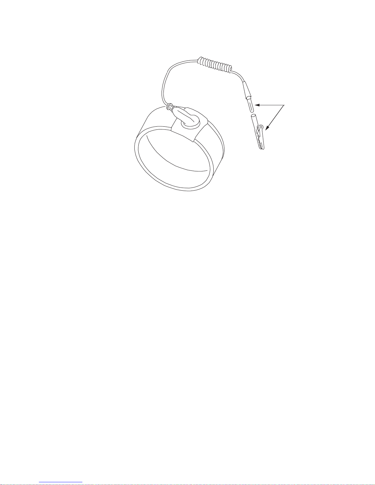
strap such as the one shown in Figur e 1, Static Control W rist S trap
(page -xxiv) or wear a heel strap and stand on a grounded, static
dissipating floor mat. If a static dissipating floor mat is used, be
sure that it is clean to ensure a good discharge path.
Page 23

About this information product
Safety Information and Instructions
...........................................................................................................................................................................................................................................................
xxiii
365-372-334 R2.0
Issue 4, November 2004
• Wear working garment made of 100% cotton to avoid electrostatic
discharge.
• Handle all circuit packs by the faceplate or latch and by the top
and bottom outermost edges. Never touch the components,
conductors, or connector pins.
• Store and ship circuit packs and components in their shipping
packing. Circuit packs and components must be packed and
unpacked only at workplaces suitably protected against build-up
of charge.
• Observe warning labels on bags and cartons. Whenever possible,
do not remove circuit packs from antistatic packaging until ready
to insert them into slots.
• If possible, open all circuit packs at a static safe work position,
using properly grounded wrist straps and static dissipating table
mats. If a static dissipating floor mat is used, be sure that it is clean
to ensure a good discharge path.
• Always store and transport circuit packs in static safe packaging.
Shielding is not required unless specified.
• Keep all static generating materials such as food wrappers,
plastics, and styrofoam containers away from all circuit packs.
Upon removal from bay, immediately put circuit packs into static
safe packages.
• Whenever possible, maintain relative humidity above 20 percent.
T o reduce the possibility of ESD damage, assemblies a re equipped with
grounding jacks to enable personnel to ground themselves using wrist
straps (Figure 1, Static Control Wrist Strap (page -xxiv)) while
handling circuit packs or working on an assembly. The jacks for
connection of wrist straps are located at the upper right-hand corner of
each assembly and are labeled. When grounding jacks are not provided,
an alligator clip adapter enables connection to bay frame ground.
Page 24
...........................................................................................................................................................................................................................................................
About this information pro d uct
Safety Information and Instructions
xxiv
365-372-334 R2.0
Issue 4, November 2004
Figure 1 Static Control Wrist Strap
..................................................................................................................
TO
GROUND
CONNECTION
Page 25

........................................................................................................................................................................
IMPORTANT SA FETY INST RUCTIO NS
READ AND UNDERST AND ALL INSTRUCTIONS
The exclamation point within an equilateral triangle is intended to alert the user to the
presence of important operating and maintenance (servicing) instructions in the literature
accompanying this product.
When installing, operating, or maintaining this equipment, basic safety precautions should always be
followed to reduce the risk of fire, electric shock, and injury to persons, including the following:
1. Read and understand all instructions
2. Follow all warnings and instructions marked on this product.
3. This product should be only operated from the type of power sources indicated on the marking label.
4. Connect this product only to the type of power sources recommended by Lucent Technologies. For
information on the powering instructions, consult the Installation Manual (DMXplore 365-372-334).
5. For information on proper mounting instructions, consult the Installation Manual (DMXplore 365-372-334).
6. Install only equipment identified in the Installation Manual (DMXplore 365-372-334). Use of other
equipment may result in improper connection of circuitry leading to fire or injury to persons.
7. All metallic telecommunication interfaces should not leave the building premises unless connected to
telecommunication devices providing primary and secondary protection, as applicable.
8. Do not use this product near water, for example, in a wet basement.
9. Do not place thi s p rod uct on an unstable cart, s ta nd or table. The product may f all, causing serious d amage to
the product.
10. Use caution when installing or modifying telecommunications lines.
11. Never install telecommunications wiring during a lightning storm.
12. Never install telecommunications connections in wet locations.
13. Never touch uninsula te d telecommunications wires or t er mi na ls u nless the telecommunicati ons li ne has been
disconnected at the network in ter f ace .
14. Never touch uninsulated wiring or terminals carrying direct current or ringing current, or leave this wiring
exposed. Protect and tape uninsulated wiring and terminals to avoid risk of fire, electric shock, and injury to
service personnel.
15. Never push objects of any kind into this product through slots as they may touch dangerous voltage points or
short out parts that could result in a risk of fire or electrical shock. Never spill liquids of any kind on the
product.
16. Slots and openings in the unit are provided for ventilation, to protect it from overheating, and these openings
must not be blocked or covered. This product should not be placed in a built-in installation unless proper
ventilation is provided.
Page 26

...........................................................................................................................................................................................................................................................
About this information pro d uct
Safety Information and Instructions
xxvi
365-372-334 R2.0
Issue 4, November 2004
17. To reduce the risk of an electrical shock, do not disassemble this product. Service should be performed by
trained personnel only. Opening or removing covers and/or circuit boards may expose you to dangerous
voltages or other risks. Incorrect reassembly can cause electrical shock when the unit is subsequently used.
18. Some of the Metropolis
®
DMX Family hardware modules contain FDA/CDRH Class I/IEC Class 1 singlemode laser products that are enclosed lightwave transmission systems. Under normal operating conditions,
lightwave transmission systems are completely enclosed; nonetheless, the following precautions must be
observed because of the potential for eye damage:
• Do not disconnect any lightwave cable or splice and stare into the optical connectors
terminating the cables.
• Lightwave/lightguide operations should not be performed by a technician who has not
satisfactorily completed an approved training course.
• Do not use optical instruments such as an eye loupe to view a fiber or unterminated connector.
• More information about laser safety can be found in the Installation Manual (DMXplore 365-
372-334).
19. For a unit intended to be powered from –48 V DC voltage sources, read and understand the following:
• To be powered only by Safety Extra Low Voltage (SELV) -48 V DC Sources.
• Disconnect up to two (2) power supply connections when removing power from the system.
• This equipment must be provided with a readily accessible disconnect device as part of the
building installation.
• Ensure that there is no exposed wire when the input power cables are connected to the unit.
• Installation must include an independent frame ground drop to building ground. Refer to User’s
Manual.
• This Equipment is to be Installed Only in Restricted Access Areas on Business and Customer
Premises Applications in Accordance with Articles 110-16, 110-17, and 110-18 of the National
Electrical Code, ANSI/NFPA No. 70. Other Installations Exempt from the Enforcement of the
National Electrical Code May Be Engineered According to the Accepted Practices of the Local
Telecommunications Utility.
20. For a unit intended to be powered from 100-120/200-240 V AC voltage sources, read and understand the
following:
• Unplug this product from the wall outlet before cleaning. Do not use liquid cleaners or aerosol
cleaners. Use a damp cloth for cleaning.
• Do not staple or otherwise attach the power supply cord to the building surfaces.
This symbol is marked on the product,
adjacent to the ground (earth) area for the
connection of the ground (earth) conductor.
Page 27

About this information product
Safety Information and Instructions
...........................................................................................................................................................................................................................................................
xxvii
365-372-334 R2.0
Issue 4, November 2004
• Do not overload wall outlets and extension cords as this can result in the risk of fire or electric
shock.
• The socket outlet shall be installed near the equipment and shall be readily accessible.
• This product is equipped with a three-wire grounding type plug, a plug having a third
(grounding) pin. This plug is intended to fit only into a grounding type power outlet. This is a
safety feature. If you are unable to insert the plug into the outlet, contact your electrician to
replace your obsolete outlet. Do not defeat the safety purpose of the grounding type plug. Do
not use a 3-to-2-prong adapter at the receptacle. Use of this type adapter may result in risk of
electrical shock and/or damage to this product.
• Do not allow anything to rest on the power cord. Do not locate this product where the cord may
be abused by persons walking on it.
• Unplug this product from the wall outlet and refer servicing to qualified service personnel
under the following conditions:
a. When the powers supply cord or plug is damaged or frayed.
b. If liquid has been spilled into the product.
c. If the product has been exposed to rain or water.
d. If the product does not operate normally by following the operating instructions. Adjust
only those controls that are covered by the operating instructions because improper
adjustment of other controls may result in damage and will often require extensive work
by qualified technician to restore the product to normal operation.
e. If the product has been dropped or the cabinet has been damaged.
f. If the product exhibits a distinct change in performance.
SAVE THESE INSTRUCTIONS
Page 28

...........................................................................................................................................................................................................................................................
About this information pro d uct
Related Documentation and Training
xxviii
365-372-334 R2.0
Issue 4, November 2004
........................................................................................................................................................................
Related Documentation and Training
Metropolis® DMX
plore
Documentation Set
Table 1, Metropolis® DMXplore Documentation Set lists the docume nts
that comprise the Metropolis® DMXplore Access Multiplexer
documentation set.
Table 1 Metropolis® DMX
plore
Documentation Set
Document
Number
Comcode Document Title Description
365-372-331 Iss.2 109454066
Metropolis
®
DMXplore Access
Multiplexer Applications and
Planning Guide (APG)
Created for use by the Lucent Account
Team, customer network planners,
analysts, and managers. It presents an
overview of the system, describes its
applications, gives plannin g
requirements, engineering rules,
ordering information, and technical
specifications.
365-372-332 R2.0 109536227
Metropolis
®
DMXplore Access
Multiplexer User Operations
Guide (UOG)
Provides step-by-step information for
use in daily system operations and
demonstrates how to perform system
provisioning, operations, and
administrative tasks.
365-372-333 R2.0 109536235
Metropolis
®
DMXplore Access
Multiplexer Alarm Messages
and Trouble Clearing Guide
(AMTCG)
Provides detailed information on
maintenance and trou ble cl earing, a list
of the system’s alarm messa ges, and
procedures for routine maintenanc e,
troubleshooting, diagnostics, and
component replacement.
365-372-334 R2.0 109536243
Metropolis
®
DMXplore Access
Multiplexer Installation Manual
(IM)
Provides a step-by-step guide to system
installation and setup.
N/A 109553073
Metropolis
®
DMXplore Access
Multiplex er Software Release
Description (SRD) - (CD -ROM)
Contains status of problems fixed,
known problems and software
installation procedure. This document
is shipped with the software CD and is
not orderable from the Customer
Information Center (CIC).
N/A 109553032
Metropolis
®
DMXplore Access
Multiplex er Software Release
Description (SRD) - (Paper)
Contains status of problems fixed,
known problems and software
installation procedure.
365-372-335 R2.0 109536250
Metropolis
®
DMXplore Access
Multiplex er TL1 Message
Details
Provides a list of TL1 commands and
the associated syntax.
Page 29

About this information product
Related Documentation and Training
...........................................................................................................................................................................................................................................................
xxix
365-372-334 R2.0
Issue 4, November 2004
Training This document expects a user to be familiar with the basic functions of
the system before performing tasks that could damage the system,
affect system operations, or impede communication traffic within the
system. Understanding the descriptive material provided in this manual
and attending the recommended training courses should allow you to
perform the tasks necessary to operate and maintain the Metropolis
®
DMXplore Access Multiplexer.
Refer to https://www.lucent-product-training.com for descriptions of the
training courses available for the Metropolis® DMXplore Access
Multiplexer.
Registering for a course
To review the available courses or to enroll in a training course at one
of Lucent’s corporate training centers,
• Within the United States,
–Visit https://www.lucent-product-training.com
–Call 1-888-LUCENT8 (888-582-3688): Prompt 2.
• Outside the continental United States,
–Visit
https://www.lucent-product-training.com
– Contact your in-country training representative
–Call: +1-407-767-2798
–Fax: +1-407-767-2677
Table 2 Metropolis® DMX
plore
Drawings
Drawing
Number
Drawing Title
ED8C947-10
Metropolis
®
DMXplore Access Multiplexer,
Engineering and Ordering Information
ED8C947-20
Metropolis
®
DMXplore Access Multiplexer,
Interconnect Circuit Information
Page 30

...........................................................................................................................................................................................................................................................
About this information pro d uct
Related Documentation and Training
xxx
365-372-334 R2.0
Issue 4, November 2004
Suitcasing
To arrange for a suitcase session at your facility,
• Within the United States, call 1-888-LUCENT8 (888-582-3688):
Prompt 2.
• Outside the continental United States,
– Contact your in-country training representative
–Call: +1-407-767-2798
–Fax: +1-407-767-2677
How to Comment To comment on this information product, go to the Online Comment
Form (http://www.lucent-info.com/comments) or email your comments
to the Comments Hotline ([email protected]).
..................................................................................................................
Page 31

About this information product
Documentation Ordering Information
...........................................................................................................................................................................................................................................................
xxxi
365-372-334 R2.0
Issue 4, November 2004
........................................................................................................................................................................
Documentation Ordering In formation
Purpose This section describes how to order:
• Additional copies of this document
• Electronic documentation (CD-ROMs)
ILEC/CLEC Customers ILEC/CLEC customers should process orders through your Company
Documentation Coordinator.
Commercial Customers Commercial customers may order standard documentation or request
placement on the standing order list (for reissues of any document) by
mail, telephone, fax, email, or the internet.
The postal address for CIC is:
Lucent Technologies
Attention: Order Entry
2855 N. Franklin Road
P.O. Box 19901
Indianapolis, IN 46219
Table 3 Ordering Documentation via Phone, Fax, or Email
Table 4 Ordering Documentation via the Internet
From Country/Region Telephone
Numbers
Fax Numbers Email
USA 1-888-LUCENT-8
(1-888-582-3688)
1-800-566-9568 [email protected]
Canada, North American
Region (NAR)
Europe, the Middle East, and
Africa (EMEA), Asia, Pacific
Region, and China; Caribbean,
Latin America (CALA)
Customer Web-SIte
Commercial C ustomers
http://www.lucentdocs.com
http://www.lucent8.com
Lucent Associates
http://www.cic.lucent.com
Page 32

...........................................................................................................................................................................................................................................................
About this information pro d uct
Documentation Ordering Information
xxxii
365-372-334 R2.0
Issue 4, November 2004
Methods of payment Lucent Associates are billed using an organization number/cost center
and location code. Commercial customers may use one of the following
methods of payment:
• Check (payable to Lucent Technologies)
• Money order (payable to Lucent Technologies)
• Invoice upon receipt of a purchase order.
(Purchase orders may be faxed or mailed using the information
provided above.)
• Credit card:
–Visa
– MasterCard
– American Express
For orders totaling $1000 or less, either a credit card or
prepayment by check/money order is required.
..................................................................................................................
Page 33

About this information product
Worldwide Se rvices
...........................................................................................................................................................................................................................................................
xxxiii
365-372-334 R2.0
Issue 4, November 2004
........................................................................................................................................................................
Worldwide Services
Overview Lucent Worldwide Services provides a full life-cycle of services and
solutions to help you plan, design, implement, and operate your
network in today's rapidly changing and complex environment.
Engineering Services Engineering Services provide information and technical support to
customers during the planning, implementation, and placement of
equipment into new or existing networks. We determine the best, most
economical equipment solution for a customer and help ensure
equipment is configured correctly for the customer’s network needs,
works as specified, and is ready for installation on delivery. These
services consist of the following:
• Equipment engineering
• Software engineering
• Site records
• Engineering consulting
• Additional engineering services (for example, Network
Realignment, System Capacity Planning, System Health
Assessment
Installation Services Lucent Technologies offers Installation Services focused on providing
the technical support and resources customers need to efficiently and
cost-effectively install their network equipment. We offer a variety of
options that provide extensive support and deliver superior execution to
help ensure the system hardware is installed, tested, and functioning as
engineered and specified. Installation Services provides a complete
flexible solution tailored to meet customers' specific needs. These
services consist of the following:
• Equipment installation
• Specialized equipment installation
• Network connectivity services
• Installation support services
..................................................................................................................
Page 34

...........................................................................................................................................................................................................................................................
About this information pro d uct
Worldwide Se rvices
xxxiv
365-372-334 R2.0
Issue 4, November 2004
Technical Support Lucent Technologies provides the following Technical Support
Services:
• Remote Technical Support (RTS) - remote technical support to
troubleshoot and resolve system problems.
• On-site Technical Support (OTS) - on-site assistance with
operational issues and remedial maintenance.
• Repair and Replacement (R&R) - technical support services for
device repair/return or parts replacement.
• Lucent OnLine Customer Support - online access to information
and services that can help resolve technical support requests.
Important! Technical Support Services are available 24 hours a
day, 7 days a week.
Customers inside the United States and Canada
Technical Support Services can be reached at 1-866-LUCENT8
(866-582-3688): Prompt 1.
Customers outside the United States
Technical Support Services can be reached at +1-630-224-4672:
Prompt 2.
Web-Site
For additional information regarding Worldwide Services, refer to the
Lucent Technologies’ web-site at http://www.lucent.com/products
1. Click on Browse the catalog
2. Click on Worldwide Services Solutions
3. Select the desired service to display:
• Engineering and Installation
• Technical Support Services
..................................................................................................................
Page 35

PART
i
365-372-334 R2.0
Issue 4, November 2004
...........................................................................................................................................................................................................................................................
Part I: Metropolis
®
DMXplore Access
Multiplexer Physical Installation
and Powering
........................................................................................................................................................................
Overview
Part I covers the physical mounting of the Metropolis® DMXplore
Access Multiplexer Wall-Mount and Rack-Mount shelf, the running
and connecting of power cables, interconnecting cables, alarm cables,
and as required, communication cables. This section also covers initial
circuit pack installation (not seated).
Important! The Metropolis
®
DMXplore Access Multiplexer
Wall-Mount shelf does not require the installation of an additional
fan unit since it was designed for natural convection cooling. The
Metropolis® DMXplore Access Multiplexer Rack-Mount shelf is
designed with an integral fan unit which provides cooling.
This section is organized into the following chapters:
• Chapter 1, Equipment and Cable Installation for Metropolis
®
DMXplore Shelf (Wall-Mount)
• Chapter 2, Equipment and Cable Installation for Metropolis
®
DMXplore Shelf (Rack-Mount)
• Chapter 3, Powering and Initial Circuit Pack Installation for
Metropolis® DMXplore Shelf (Wall-Mount)
• Chapter 4, Powering and Initial Circuit Pack Installation for
Metropolis
®
DMXplore Shelf (Rack-Mount)
..................................................................................................................
Page 36

...........................................................................................................................................................................................................................................................
Metropolis® DMXplore Access Multiplexer Physic al
Installation and Powering
PARTI
ii
365-372-334 R2.0
Issue 4, November 2004
Page 37

Metropolis® DMXplore Access Multiplexer Physic al
Installation and Powering
...........................................................................................................................................................................................................................................................
PART
iii
365-372-334 R2.0
Issue 4, November 2004
Tools, Test Equipment, and Accessories
Overview
This section lists the tools, test equipment and accessories needed to
perform all the procedures in this installation manual.
Tools, Test Equipment and
Accessories
Listed below are the required tools, test equipment and accessories.
Quantity Description Comments
1 or 2
per shelf
AC/DC Wall-Mount
Power Converter
(408812394)
The AC/DC W all-Mo unt converter allows the Metropolis
®
DMXplore
to be powered using a AC voltage supply. The converter requires a
standard 110V AC input 3-prong power cord which can be ordered
separately. It includes one bracket and the DC cable pigtail
connection to the Metropolis
®
DMXplore.
1 3-prong power cord
Power cord is required to power the AC/DC Wall-Mount power
converter and is ordered separately.
1
12" Rack Bracket for
Wall-Mount DMXplore
(848945424)
The 12" mounting brackets must be ordered separately and are
required to install the Metropolis
®
DMXplore in a 12" bay-frame. The
12" mounting bracket supports one Metropolis
®
DMXplore shelf and
an AC/DC converter.
19" Rack Bracket for
Wall-Mount
DMXplore
(848945432)
The 19" mounting brackets must be ordered separately and are
required to install the Metropolis
®
DMXplore in a 19" bay-frame. The
19" mounting bracket supports one Metropolis
®
DMXplore shelf and
an AC/DC converter.
23" Rack Bracket for
Wall-Mount
DMXplore
(848945440)
The 23" mounting bracket mus t be ordered s eparately and ar e required
to install the Metropolis
®
DMXplore in a 23" bayframe. The 23"
mounting bracket supports two Metropolis
®
DMXplore shelves and
two AC/DC converters.
1
Heat Baffle
(848862181)
If the
Metropolis® DMXplore Wall-Mount shelf is to be installed
above or below existing equipment in a rack that does not have a
heat baffle, then a heat baffle must be installed between the
shelf and the existing equipment. If there is space left in the bayframe above the last
Metropolis® DMXplore shelf installed, a heat
baffle must be installed above the shelf to prevent accidental
damage to the power cables at the top of the shelf.
Screwdriver(s) A screwdriver(s) with the appropriate head(s) is (are) required for
securing the mounting screws, repositioning the mounting brackets,
and installing the interfacing cables.
1 RJ-45 Crimping tool
The crimping tool is required for terminating DS1 blunt-cut cables to
a RJ-45 connector.
Page 38

...........................................................................................................................................................................................................................................................
Metropolis® DMXplore Access Multiplexer Physic al
Installation and Powering
PARTI
iv
365-372-334 R2.0
Issue 4, November 2004
1Wire-Wrap Gun
R-4496A
The wire-wrap gun is re qui red for terminating DS1 ca bl e an d must be
able to accommodate 24-gauge wire.
1 ESD Wrist Strap
R-4987C
A wrist strap must be worn when handling circuit packs. Use the
electrostatic discharge (ESD) jack provided on the shelf.
1 Torque Wrench
(R-5952)
A torque wrench (50-250 IN-LBS) is used when tightening the
Metropolis
®
DMXplore shelf to the fr ame. It is also used when
reattaching the mounting brackets to the Metropolis
®
DMXplore
shelf.
1 Torque Screwdriver A torque screwdriver is used to attach the 48 Volt wiring to the
terminal block.
1 Metric & Inch Series
Tool Set
R - 6001
Because some Optical Net w ork ing Products (also know as Transport)
may have some metric fasteners, please ensure that the proper metric
tools are available.
1 Multimeter (Optional)
ITE-6379C
The voltmeter must be capable of measuring DC voltage in the 40 to
60 volt range. The use of the voltmeter is optional since the shelf will
alarm or shut down if the proper voltage is not supplied.
1Ohmmeter
ITE-6379C
An ohmmeter is required to verify that the Metropolis
®
DMXplore is
properly grounded.
1 DS1 Error Rate Test Set
ITE-7113
A DS1 error rate test set is required for testing of DS1 cabling. A TBERD 2209 or equivalent is recommended.
2 LC-type Optical Fiber
Jumper ITE-7169
(109462168)
Two optical fiber jumpers with LC type connectors are required to
optically lo op the Metropol is
®
DMXplore shelf for test purposes.
1 Noyes OFS 300-200X
Optical Fiber Scope
ITE-7129
This equipment may not be necessary at all locations. It is to be used
when the po rts need to be verified for cleanliness. If care is exer cised
when cleaning fibers, the optical fiber scope may not be needed.
1 2.5mm Universal
adapter cap ITE-7129
D1
For use with the Noyes OFS 300-200X Optical Fiber Scope.
1 1.25mm Universal
adapter cap ITE-7129
D2
Quantity Description Comments
Page 39

Metropolis® DMXplore Access Multiplexer Physic al
Installation and Powering
...........................................................................................................................................................................................................................................................
PART
v
365-372-334 R2.0
Issue 4, November 2004
1 Noyes VFS-1 ITE-7187
Video Fiber Scope
1
This equipment may not be necessary at all locations. It is to be used
when the po rts need to be verified for cleanliness. If care is exer cised
when cleaning fibers, the video scope may not be needed.
varies Individual presaturated
alcohol wipes ITE-7136
99% pure isopropyl alcohol
1 CLETOP Cleaning
Cassette ITE-7137
Type A Reel
1 CLETOP Cleaning
Cassette Replacement
Reel
ITE-7137 D1
Type A Reel
1 Luminex Stick port
cleaners ITE-7134 &
ITE-7135
1.25 mm and 2.5 mm sizes
1 Luminex Cloth R-6033 5.5” x 5.5”
Quantity Description Comments
Page 40

...........................................................................................................................................................................................................................................................
Metropolis® DMXplore Access Multiplexer Physic al
Installation and Powering
PARTI
vi
365-372-334 R2.0
Issue 4, November 2004
PC and Cable
Requirements for
WaveStar
®
CIT
This section lists the required and optional equipment needed to run the
WaveStar® CIT software with the Metropolis® DMXplore.
PC Minimum Requirements
• Windows® NT (with SP5 for Y2K compliance), Windows® 2000
or Windows® XP Operating Systems
• 128 MByte of RAM (minimum for 1 system view), 256 MByte
recommended (up to 5 system views)
• 139 MByte Virtual Memory (minimum), 267 MByte
recommended
• SVGA monitor set to 800x600 resolution or greater, with 256
colors (1024x768, 16 million colors recommended)
• 500 MByte memory available on hard drive (minimum), 550
MByte Recommended
• CD-ROM drive
• 10/100 BaseT LAN interface (network interface card, NIC)
• Pentium 2, 266 MHz Processor (minimum), Pentium III, 500MHz
recommended
Important! Minimum requirements are sufficient to run two to
three System GUI views, unless otherwise noted. Recommended
requirements are intended to be used as a general guideline to
optimize WaveStar
®
CIT performance. As the CIT is used with
multiple NE connections and multiple NE types, the processor type
Quantity Required Description Comm ents
1 Y Personal Computer (PC) See PC Minimum Requirements below.
1Y
CIT Interface Cable
(848748869)
8-ft. long RJ45 to 9-pin D-sub serial cable.
LAN 10BASE-T (Crossover) Allows for direct connection between the
PC LAN card and the CTL LAN slot. See
Table 1-17, LAN 10BASE-T Cross-over
Cable Connections (page 1-47) for
Comcode in formation.
LAN 10BASE-T (StraightThrough)
Allows for connect ion betwe en the PC NIC
card and a HUB. See Table 1-18, LAN
10BASE-T Straight-through Cable
Connections (page 1-47) for Comcode
information.
Page 41

Metropolis® DMXplore Access Multiplexer Physic al
Installation and Powering
...........................................................................................................................................................................................................................................................
PART
vii
365-372-334 R2.0
Issue 4, November 2004
and speed as well as the memory size will all factor in to CIT
performance.
Page 42

...........................................................................................................................................................................................................................................................
Metropolis® DMXplore Access Multiplexer Physic al
Installation and Powering
PARTI
viii
365-372-334 R2.0
Issue 4, November 2004
Page 43
1-1
365-372-334 R2.0
Issue 4, November 2004
............................................................................................................................................................................................................................................................
1 Equipment and Cable Installation
for Metropolis
®
DMXplore Shelf
(Wall-Mount)
............................................................................................................................................................................................................................................................
Overview
Purpose This section provides installation and cabling instructions for the
Metropolis® DMXplore Wall-Mount Shelf.
Mounting options for the Wall-Mount unit are:
1. Wall
2. Bay-frame (using optional equipment)
Contents This chapter provides information on the following topics:
Planning 1-3
Connector References 1-7
Inspection 1- 8
Metropolis
®
DMXplore Wall-Mount Shelf Installation 1-9
Power Cable Installation 1-18
DS1 Cable Installation 1-23
DS3 Cable Installation 1-27
Ethernet Cable Installation 1-30
Miscellaneous (Environment al) Discrete Telemetry Cable
Installation
1-37
1-37
1-30
1-27
1-23
1-18
1-9
1-8
1-7
1-3
Page 44

...........................................................................................................................................................................................................................................................
Equipment and Cable Installation for Metropolis
®
DMXplore Shelf (Wall-Mount)
Overview
1-2
365-372-334 R2.0
Issue 4, November 2004
OC-3/OC12 Main Optical Fiber Cable Installation 1-41
RS-232 Serial CIT Cable Installation 1-43
SYSCTL LAN Cable Installation 1-45
Final Operations 1-49
1-49
1-45
1-43
1-41
Page 45

Equipment and Cable Installation for Metropolis
®
DMXplore Sh elf (Wall-Mount)
Planning
...........................................................................................................................................................................................................................................................
1-3
365-372-334 R2.0
Issue 4, November 2004
............................................................................................................................................................................................................................................................
Planning
Description This section provides information about the following:
• tools, test equipment and accessories
• mounting options
• cabling checklist
...........................................................................................................................................................................
Tools, Test Equipment and
Accessories
Listed below are the tools, test equipment and accessories necessary to
perform the procedures in this section.
Quantity Description Comments
1 or 2
per shelf
AC/DC Wall-Mount Power
Converter
(408812394)
The AC/DC Wall-Mount converter allows the
Metropolis
®
DMXplore to be powered using a AC
voltage supply.
The acceptable AC input voltage
range for the AC/DC power supply is 85 VAC
to 264V AC. It includes one bracket and the DC
cable pigtail connection to the Metropolis
®
DMXplore.
1 3-prong power cord
Power cord is required to power the AC/DC WallMount power converter and is ordered separately.
1
12" Rack Bracket for WallMount DMXplore
(848945424)
The 12" mounting brackets must be ordered
separately and are required to install the Metropolis
®
DMXplore in a 12" bay-frame. The 12" mounting
bracket supports one Metropolis
®
DMXplore shelf
and an AC/DC converter.
19" Rack Bracket for WallMount
DMXplore
(848945432)
The 19" mounting brackets must be ordered
separately and are required to install the Metropolis
®
DMXplore in a 19" bay-frame. The 19" mounting
bracket supports one Metropolis
®
DMXplore shelf
and an AC/DC converter.
23" Rack Bracket for WallMount
DMXplore
(848945440)
The 23" mounting bracket must be ordered
separately and are required to install the Metropolis
®
DMXplore in a 23" bayframe. The 23" mounting
bracket supports two Metropolis
®
DMXplore
shelves and two AC/DC converters.
Page 46

...........................................................................................................................................................................................................................................................
Equipment and Cable Installation for Metropolis
®
DMXplore Shelf (Wall-Mount)
Planning
1-4
365-372-334 R2.0
Issue 4, November 2004
1
Heat Baffle
(848862181)
If the Metropolis
®
DMXplore Wall-Mount shelf is
to be installed above or below existing
equipment in a rack that does not have a heat
baffle, then a heat baffle must be installed
between the shelf and the existing equipment. If
there is space left in the bay-frame above the
last Metropolis
®
DMXplore shelf installed, a heat
baffle must be installed above the shelf to
prevent accidental damage to the power cables
at the top of the shelf.
Screwdriver(s) A screwdriver(s) with the appropriate head(s) is
(are) required for securing the mounting screws,
repositioning the mounting brackets, and installing
the interfacing cables.
1 RJ-45 Crimping tool
The crimping tool is required for terminating DS1
blunt-cut cables to a RJ-45 connector.
1 Wire-Wrap Gun
R-4496A
The wire-wrap gun is required for terminating DS1
cable and must be able to accommodate 24-gauge
wire.
1 ESD Wrist Strap
R-4987C
A wrist strap must be worn when handling circuit
packs. Use the electros t atic discharge (ESD) jack
provided on the shelf.
1 Torque Wrench
(R-5952)
A torque wrench (50-250 IN-LBS) is used when
tightening the Metropolis
®
DMXplore shelf to the
frame. It is also used when reattaching the mounting
brackets to the Metropolis
®
DMXplore shelf.
1 Torque Screwdriver A torque screwdriver is used to attach the 48 Volt
wiring to the terminal blo ck.
1 Metric & Inch Series Tool
Set
R - 6001
Because some Optical Networking Products (also
know as Trans port) may ha ve some metr ic fastener s,
please ensure that the proper metric tools are
available.
1 Multimeter ( Optional)
ITE-6379C
The voltmeter must be capable of measuring DC
voltage in the 40 to 60 volt range. The use of the
voltmeter is optional since the shelf will alarm or
shut down if the proper voltage is not supplied.
1Ohmmeter
ITE-6379C
An ohmmeter is required to verify that the
Metropolis
®
DMXplore is properly grounded.
Quantity Description Comments
Page 47

Equipment and Cable Installation for Metropolis
®
DMXplore Sh elf (Wall-Mount)
Planning
...........................................................................................................................................................................................................................................................
1-5
365-372-334 R2.0
Issue 4, November 2004
Mounting options The Wall-Mount mounting brackets for the Metropolis
®
DMXplore
Access Multiplexer are designed to allow for mounting in the
following:
• 12-inch bay-frames
• 19-inch bay-frames
• Standard 23-inch wide network bay-frames
The recommended network bay-frames are the ED-8C500-50 and
the ED-8C501-50 (also allows for rear access).
• 23-inch seismic network bay-frame
The ED-8C800-50 and ED-8C801-50 seismic network bay-frames
are designed for use in all earthquake zones, and in general, do not
require top support at the 7-foot level. These frames meet Pacific
Bell Equipment Framework Standard PBS-000-102PT.
• 23-inch wide EIA-Type bay-frames
Cabling checklist This section briefly describes cabling information, including the
number of particular cables required. For information regarding
available cable lengths and ordering comcodes, refer to the tables in
this chapter.
Table 1-1, Cable Requirements and Options lists available cables along
with the required number (if any).
Notes:
1. One -48VA and -48VB main power feeder is required per shelf. Each
power feed needs to have an external 2A fuse.
2. One CIT Cable Assembly is required for PC serial interface with the
Table 1-1 Cable Requirements and Options
Cable Assembly Description Required See Note
Power Yes 1
CIT
Yes 2
LAN 10BASE-T (Cross-over)
LAN 10BASE-T (Straight-
Through)
DS1 Optional 3
DS3 Optional 4
Office Alarm Optional 5
Miscellaneous Discrete Optional
Page 48

...........................................................................................................................................................................................................................................................
Equipment and Cable Installation for Metropolis
®
DMXplore Shelf (Wall-Mount)
Planning
1-6
365-372-334 R2.0
Issue 4, November 2004
Metropolis® DMXplore (not included with equipment).
3. One "Single DS1 Cable Assembl y" is require d for each DS1 s upported by
the main pack (maximum of 16). Each DS1 Cable Assembly supports 1
pair of 24-gauge RJ45/blunt-cut or RJ45-RJ45 cables. One cable is for
input and output signals.
4. One "Single DS3 Cable Assembl y" is require d for each DS3 s upported by
the main pack. One code provides 1 DS3 input and 1 DS3 output, 735A
coaxial Straight BNC plug to Straight BNC plug.
5. When cabling the Metropolis
®
DMXplore for office alarm applications,
one Office Alarm Cable Assembly is required for each Metropolis
®
DMXplore shelf.
6. When accessing the shelf through the LAN (OSI/TCP-IP) connection,
either a LAN 10BASE-T cross- over cable or a LAN 10BASE-T strai ght through cable is requ ired to acc ess the shel f. The cross- over cable should
be used when connecting directly between the shelf from a PC NIC car d.
The straight-th rou gh c abl e s hould be used when connec ti ng the shelf to a
hub.
...........................................................................................................................................................................
Page 49
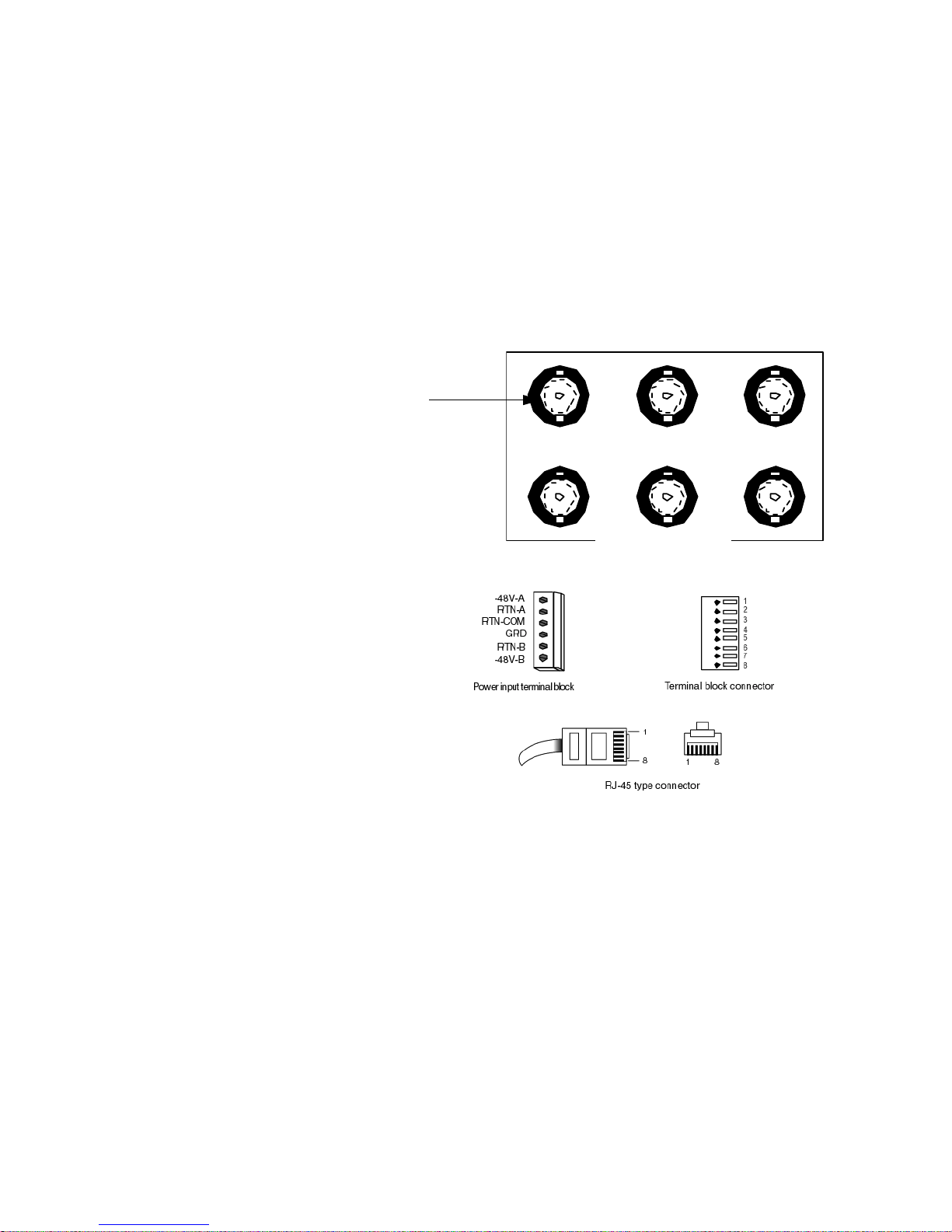
Equipment and Cable Installation for Metropolis
®
DMXplore Sh elf (Wall-Mount)
Connector References
...........................................................................................................................................................................................................................................................
1-7
365-372-334 R2.0
Issue 4, November 2004
............................................................................................................................................................................................................................................................
Connector References
Description Figure 1-1, Connector Types and Pinouts (page 1-7) provides the
pinouts of some of the connectors used to interface with the
Metropolis® DMXplore.
Figure 1-1 Connector Types and Pinouts
123
B GROUP
RX
TX
RX
TX
BNC
Connector
Page 50

...........................................................................................................................................................................................................................................................
Equipment and Cable Installation for Metropolis
®
DMXplore Shelf (Wall-Mount)
Inspection
1-8
365-372-334 R2.0
Issue 4, November 2004
............................................................................................................................................................................................................................................................
Inspection
Description Perform the following procedure before installing the Metropolis
®
DMXplore shelf and cables.
...........................................................................................................................................................................
Procedure
Step 1
Inspect the shelf for visible damage including bent or touching
backplane pins.
If any backplane pins are damaged, refer to Appendix D, Backplane Pin
Replacement for instructions on repairing the damaged pin(s).
...........................................................................................................................................................................
Step 2 Each Wall-Mount Metropolis
®
DMXplore shelf comes with a bag
containing the following items:
Verify that the bag is available and contains the items listed above.
...........................................................................................................................................................................
Step 3 Check off the appropriate box in Appendix E, Installation Checklist.
End of Steps
...........................................................................................................................................................................
Quantity Description
4 8 X .75" Long Pan Head Wood Screws
1 Safety Insttruction Sheet
Page 51

Equipment and Cable Installation for Metropolis
®
DMXplore Sh elf (Wall-Mount)
Metropolis® DMXplore Wa ll-Mount Shelf
Installation
...........................................................................................................................................................................................................................................................
1-9
365-372-334 R2.0
Issue 4, November 2004
............................................................................................................................................................................................................................................................
Metropolis® DMXplore Wall-Mount Shelf Installation
Introduction This section provides instructions for mounting the Metropolis
®
DMXplore Wall-Mount on a wall and in the supported bay-frames
sizes using the appropriate bracket.
Installation Note s:
1. When wall mounting 3" top clearance, 1" bottom clearance, and
.5" side clearances are required for natural convection cooling.
2. When mounting the Metropolis® DMXplore unit above power
dissipating equipment an appropriate heat baffle is required.
Maximum operating temperature is 65° C.
3. When being used in an outdoor cabinet (or other environments
allowing for ambient temperatures up to 65° C), the minimum
required airflow is 200 fpm.
4. The maximum weight of the Metropolis® DMXplore Wall-Mount
shelf, fully equipped is 4.77kg (10.5 lbs).
Wall installation The Metropolis
®
DMXplore Wall-Mount is a front access design that
allows for it to be mounted directly against a flat surface. The following
steps describe mounting the shelf on a wall.
Installation Note :
Wall mount mounting hardware is included with the Wall-Mount
Metropolis® DMXplore shelf code.
Procedure
Step 1
Position the Metropolis® DMXplore shelf on a stable work surface.
Important! Front cover is shipped with a clear protective liner
over the outside surface of the viewing window of cover. Peel and
remove. See Figure 1-2, Metropolis® DMXplore Shelf Wall-Mount
(with Cover) (page 1-10).
Page 52
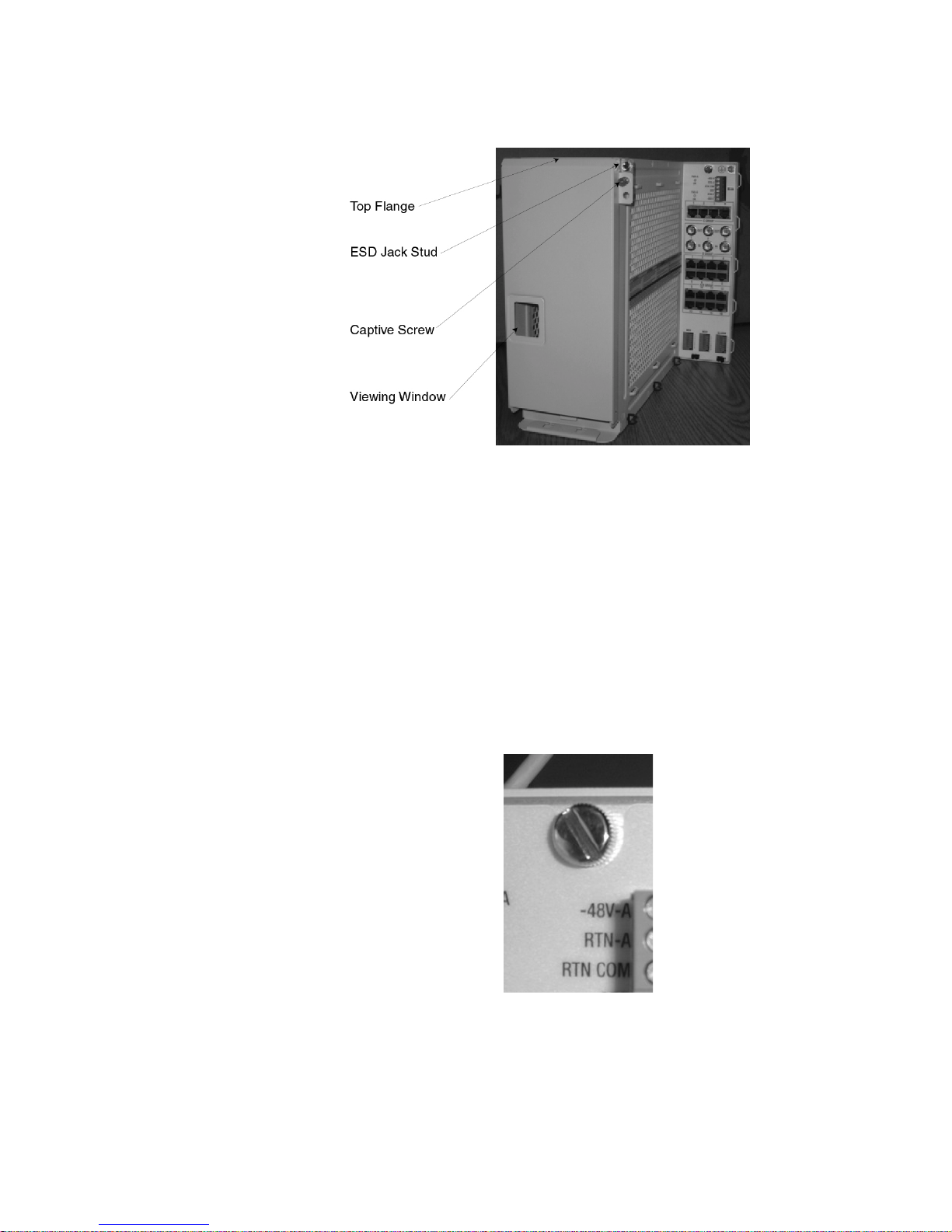
...........................................................................................................................................................................................................................................................
Equipment and Cable Installation for Metropolis
®
DMXplore Shelf (Wall-Mount)
Metropolis® DMXplore Wa ll-Mount Shelf
Installation
1-10
365-372-334 R2.0
Issue 4, November 2004
Figure 1-2 Metropolis® DMX
plore
Shelf Wall-Mount (wi th Cover)
...........................................................................................................................................................................
Step 2 Remove wall-plate from the rear of the Wall-Mount Metropolis
®
DMXplore Shelf by doing the following:
1. Loosen the mounting screw in the top right hand corner of
the Access Panel. See Figure 1-2, Metropolis® DMXplore
Shelf Wall-Mount (with Cover) (page 1-10).
2. Slide shelf up along wall plate until it clears the mounting
tabs. See Figure 1-3, Mounting Screw (page 1-10)
3. Separate shelf from wall plate.
Figure 1-3 Mounting Screw
Page 53
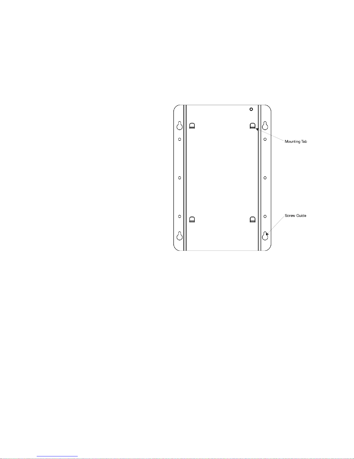
Equipment and Cable Installation for Metropolis
®
DMXplore Sh elf (Wall-Mount)
Metropolis® DMXplore Wa ll-Mount Shelf
Installation
...........................................................................................................................................................................................................................................................
1-11
365-372-334 R2.0
Issue 4, November 2004
...........................................................................................................................................................................
Step 3 Determine the wall mounting location for the Wall-Mount Metropolis
®
DMXplore shelf.
Important! Use wall plate as a stencil to mark screw positions.
Figure 1-4 Wall Plate
...........................................................................................................................................................................
Step 4 Secure the wall plate to 3/4" plywood or wall studs at the desired
location using included #8 X .75" long Pan Head Wood Screws (4
supplied with the shelf).
Important! See Installation Notes: (1-9) for required clearances.
...........................................................................................................................................................................
Step 5 Position the Metropolis
®
DMXplore shelf onto the mounting tabs and
secure to wall plate using the mounting screw. See Figure 1-3,
Mounting Screw (page 1-10).
...........................................................................................................................................................................
Step 6 Attach grounding wire between shelf safety ground screw and
appropriate safety ground. See Figure 1-7, Safety Ground Screw (page
1-15).
Page 54

...........................................................................................................................................................................................................................................................
Equipment and Cable Installation for Metropolis
®
DMXplore Shelf (Wall-Mount)
Metropolis® DMXplore Wa ll-Mount Shelf
Installation
1-12
365-372-334 R2.0
Issue 4, November 2004
Important! Grounding wire must be of the same gauge as the
cables used to power the shelf.
Figure 1-5 Safety Ground Screw
...........................................................................................................................................................................
Step 7 Verify with an ohmmeter that the Metropolis
®
DMXplore shelf is
grounded properly. Measure between the Metropolis
®
DMXplore shelf
safety ground screw and the appropriate safety ground.
Requirement: The ohmmeter reads less than 1 ohm.
...........................................................................................................................................................................
Step 8 Verify with an ohmmeter that the ESD jack on the front of the shelf is
grounded properly. Measure between the ESD jack stud and the
appropriate safety ground.
See Figure 1-2, Metropolis® DMXplore Shelf Wall-Mount (with Cover)
(page 1-10)
Requirement: The ohmmeter reads less than 1 ohm.
...........................................................................................................................................................................
Step 9 If using the AC/DC converter (408812394), mount it at least 3" above
the DMXplore with its 3’ DC cable towards the DMXplore and its AC
connection facing up, away from the DMXplore .
...........................................................................................................................................................................
Step 10 Check off the appropriate box in Appendix E, Installation Checklist.
End of Steps
...........................................................................................................................................................................
Page 55

Equipment and Cable Installation for Metropolis
®
DMXplore Sh elf (Wall-Mount)
Metropolis® DMXplore Wa ll-Mount Shelf
Installation
...........................................................................................................................................................................................................................................................
1-13
365-372-334 R2.0
Issue 4, November 2004
12-inch, 19-inch, and 23-
Inch Bay-frame Installation
As an example of the Metropolis® DMXplore shelf installation, the
following steps describe mounting a single shelf from the front of a 23inch bay-frame. Mounting from the rear of a 23-inch bay-frame or from
the front/rear of a 12-inch or 19-inch bay-frame is similar with the
exception of the type and mounting position of the brackets.
See Figure 1-8, Wall-Mount Bay-Frame Mounting Brackets (page
1-17)
The 23-inch frame supports two Metropolis® DMXplore shelves. To
mount a second shelf repeat this procedure for the second shelf at the
second mounting position.
Important! This section requires previous bay-frame installation
and grounding.
Procedure
Step 1
Position the Metropolis® DMXplore shelf on a stable work surface.
Important! Front cover is shipped with a clear protective liner
over the outside surface of the viewing window of cover. Peel and
remove. See Figure 1-2, Metropolis® DMXplore Shelf Wall-Mount
(with Cover) (page 1-10).
...........................................................................................................................................................................
Step 2 Determine the mounting configuration for the Metropolis
®
DMXplore
shelf:
• type of bay-frame (23-inch, 19-inch or 12-inch wide)
• mounting position (front, rear)
• shelf position for 23-inch frame (right, left)
• position in bay (bottom to top)
Important! The mounting brackets must be ordered separately
and are required to install the Metropolis® DMXplore in a
bayframe. See Tools, Test Equipment and Accessories (1-3)
Important! If mounting two Metropolis
®
DMXplore shelves in a
23" rack application cable access is moderately restricted.
Important! A front mounting position results in a 5" protrusion
from the front of bay-frame.
Page 56
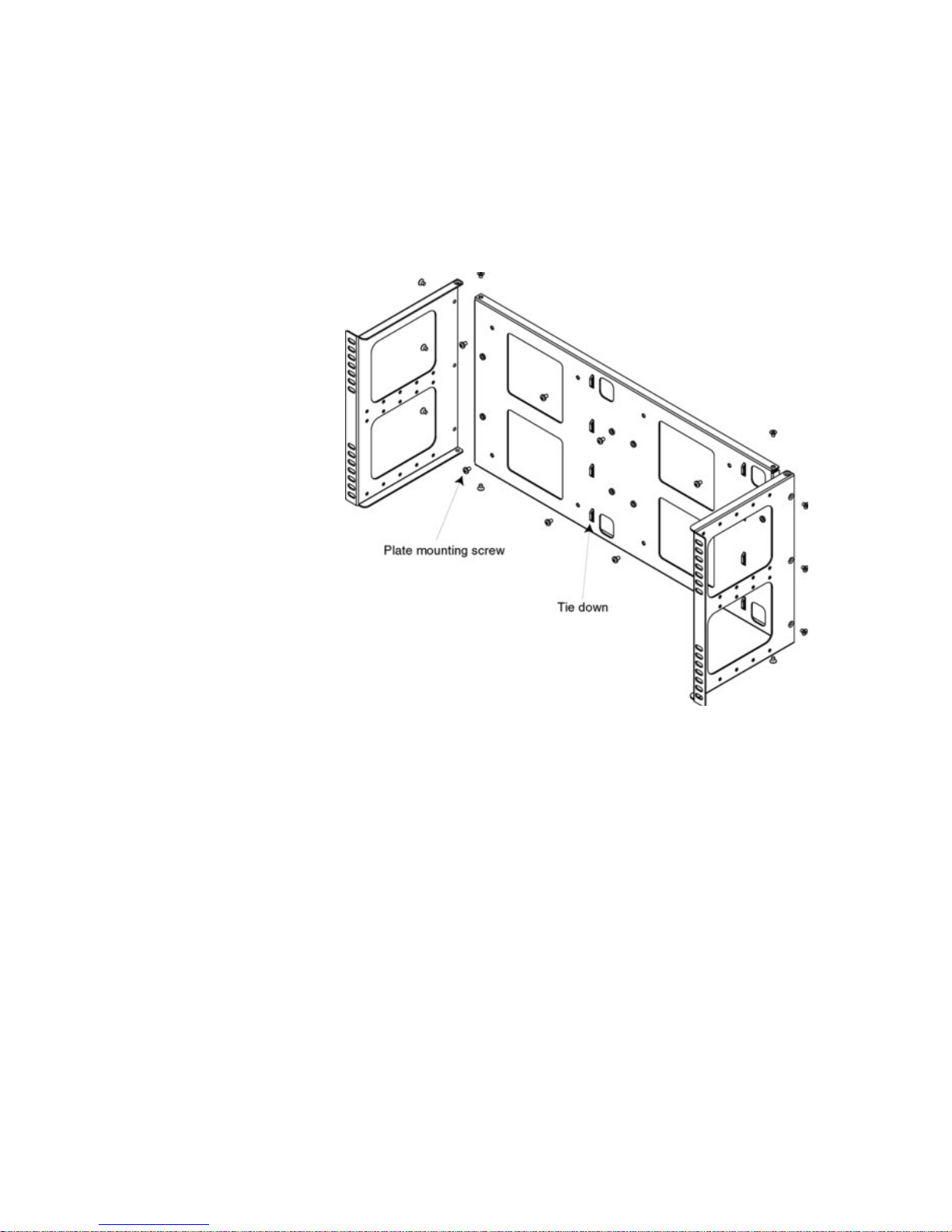
...........................................................................................................................................................................................................................................................
Equipment and Cable Installation for Metropolis
®
DMXplore Shelf (Wall-Mount)
Metropolis® DMXplore Wa ll-Mount Shelf
Installation
1-14
365-372-334 R2.0
Issue 4, November 2004
...........................................................................................................................................................................
Step 3 Remove bay-frame mounting bracket from box, and assemble as
indicated in Figure 1-6, Exploded Bay-Frame (23" Mounting Bracket)
(page 1-14).
Figure 1-6 Exploded Bay-Frame (23" Mounting Bracket)
Important!
Tie-downs are to be positioned to the right of the
shelf.
...........................................................................................................................................................................
Step 4 Determine the position that the bay-frame mounting bracket will be
mounted. As a general rule, start at the bottom of the bay and add
shelves from bottom to top.
Important! If the Metropolis
®
DMXplore shelf is to be installed
above or below existing equipment that does not have a heat baffle,
then a heat baffle (C848862181) must be installed between the shelf
and the existing equipment.
Important! If there is space left in the bayframe above the last
Metropolis® DMXplore bracket assembly installed, a heat baffle
Page 57

Equipment and Cable Installation for Metropolis
®
DMXplore Sh elf (Wall-Mount)
Metropolis® DMXplore Wa ll-Mount Shelf
Installation
...........................................................................................................................................................................................................................................................
1-15
365-372-334 R2.0
Issue 4, November 2004
must be installed above the shelf to prevent accidental damage to
the power cables at the top of the shelf.
...........................................................................................................................................................................
Step 5 Position the bay-frame mounting bracket in the frame and secure to the
frame using 3 thread-forming screws side (not included). Tighten the
screws to 21 in.-lb. (minimum)/30 in.-lb. (maximum)
Important! Grounding wire must be of the same gauge as the
cables used to power the shelf.
Important! Be sure to mount the shelf using thread-forming
screws to ensure a solid ground connection from the bay to the
shelf.
Important! For bays that use powder coat paint e.g. most 19"
bays, studies on that type of paint indicate that the material is not
always removed cleanly using the thread forming screws and can
create a poor ground, thus we recommend a secondary ground be
used. The secondary ground would consist of a 12 AWG wire from
the UL (Green M5 Screw) safety ground to the bayframe (where the
bayframe has been scraped clean of paint and treated with no-ox)
See Figure 1-7, Safety Ground Screw (page 1-15).
Figure 1-7 Safety Ground Screw
...........................................................................................................................................................................
Step 6 Remove wall plate from the rear of the Metropolis
®
DMXplore Shelf
by doing the following:
1. Loosen the mounting screw in the top left hand corner of the
Access Panel. See Figure 1-3, Mounting Screw (page 1-10).
2. Slide shelf up along wall plate until it clears the mounting
tabs. See Figure 1-4, Wall Plate (page 1-11).
3. Separate shelf from wall plate.
Page 58

...........................................................................................................................................................................................................................................................
Equipment and Cable Installation for Metropolis
®
DMXplore Shelf (Wall-Mount)
Metropolis® DMXplore Wa ll-Mount Shelf
Installation
1-16
365-372-334 R2.0
Issue 4, November 2004
...........................................................................................................................................................................
Step 7 Loosen plate mounting screws on mounting bracket and position wall-
plate onto it.
See Figure 1-6, Exploded Bay-Frame (23" Mounting Bracket) (page
1-14)
...........................................................................................................................................................................
Step 8 Tighten plate mounting screws to firmly attach wall plate to the
mounting bracket.
...........................................................................................................................................................................
Step 9 Position shelf onto mounting tabs of the wall plate and tighten
mounting screw in the top left hand corner of the access panel.
See Figure 1-3, Mounting Screw (page 1-10)
...........................................................................................................................................................................
Step 10 Verify with an ohmmeter that the Metropolis
®
DMXplore shelf is
grounded to the bay-frame. Measure between the Metropolis
®
DMXplore shelf mounting bracket and the safety ground lug on the
bay-frame.
Requirement: The ohmmeter reads less than 1 ohm.
...........................................................................................................................................................................
Step 11 Verify with an ohmmeter that the ESD Jack Stud See Figure 1-2,
Metropolis® DMXplore Shelf Wall-Mount (with Cover) (page 1-10) is
grounded to the bay-frame. Measure between the ESD Jack Stud and
the safety ground lug on the bay-frame.
Requirement: The ohmmeter reads less than 1 ohm.
Important! If using the AC/DC converter (408812394), it may be
desirable to mount the converter(s) to the rear of the shelf at this
time. A single converter can be mounted on the rear of the 12" and
19" mounting brackets, whereas the 23" mounting bracket supports
up to two AC/DC converters.
...........................................................................................................................................................................
Step 12 Check off the appropriate box in Appendix E, Installation Checklist.
End of Steps
Page 59
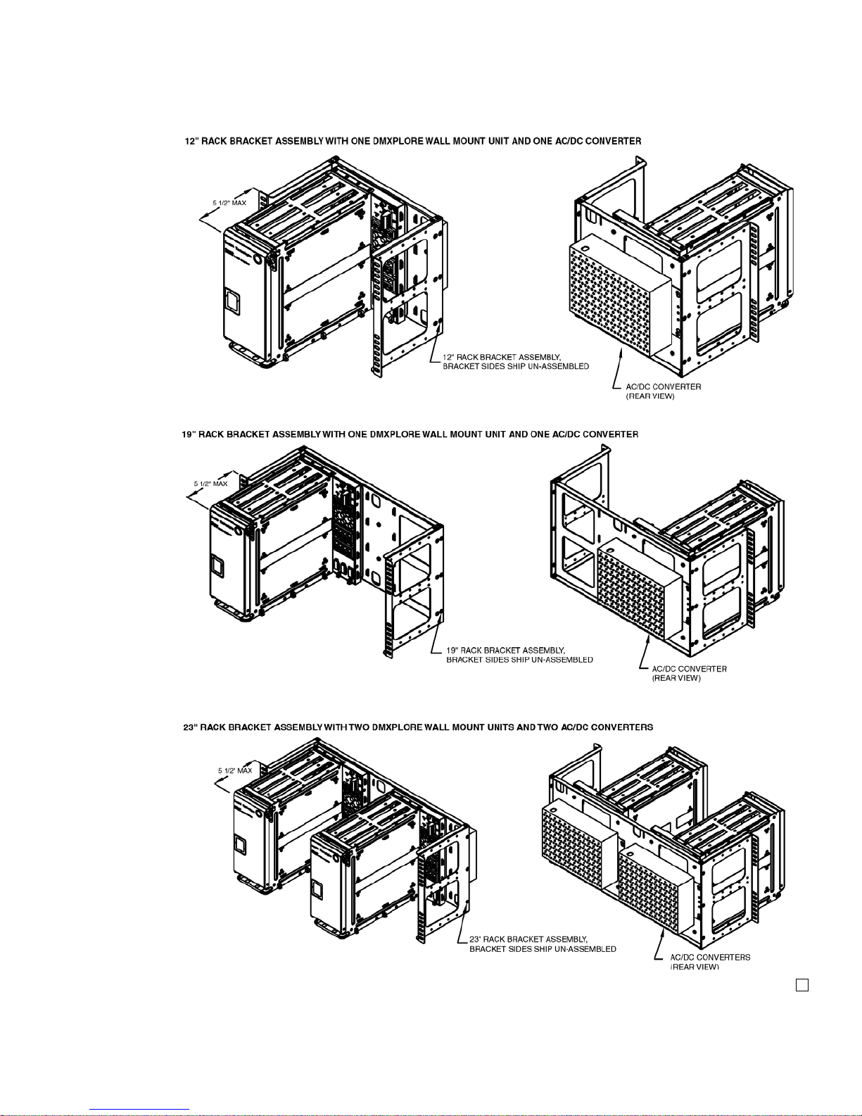
Equipment and Cable Installation for Metropolis
®
DMXplore Sh elf (Wall-Mount)
Metropolis® DMXplore Wa ll-Mount Shelf
Installation
...........................................................................................................................................................................................................................................................
1-17
365-372-334 R2.0
Issue 4, November 2004
Figure 1-8 Wall-Mount Bay-Frame Mounting Brackets
Page 60

...........................................................................................................................................................................................................................................................
Equipment and Cable Installation for Metropolis
®
DMXplore Shelf (Wall-Mount)
Power Cable Installation
1-18
365-372-334 R2.0
Issue 4, November 2004
............................................................................................................................................................................................................................................................
Power Cable Installation
Description This section provides instructions on installing the power cabling for
the Metropolis® DMXplore shelf.
Each power feeder (A and B) requires a single power feed from; the
AC/DC power converter (408812394), the battery distribution fuse
board (BDFB), or the battery distribution circuit breaker bay (BDCBB)
to the Metropolis® DMXplore shelf.
If the Metropolis® DMXplore is powered through only one power feed,
the system will report a minor alarm. To suppress the alarm, use two
jumpers between the 48VA and 48 VB attachment positions (A- to Band A+ to B+). The gauge of both jumpers should be the same as the
gauge being brought in from either the Battery Plant or from the
MASCOT AC/DC Supply (#12AWG to #20AWG).
Table 1-2, Power Cable Assemblies and Table 1-3, Power Connections
(page 1-18) lists the available power cable assemblies and power
connections, respectively.
Table 1-2 Power Cable Assemblies
Description Cable
Assembly #
Cable
Length (feet)
Color
Coding
AC Power Cables
848822201 10
848822219 20
848822227 40
DC Power cable 12
AWG, 4
conductors
848946687 30
Table 1-3 Power Connections
Shelf Power Designation Name
BAT A -48-A BAT A
RTN-A BAT A RTN
Page 61

Equipment and Cable Installation for Metropolis
®
DMXplore Sh elf (Wall-Mount)
Power Cable Installation
...........................................................................................................................................................................................................................................................
1-19
365-372-334 R2.0
Issue 4, November 2004
Important! To tie RTN-A and RTN-B together use a MESH
Ground Strap to jumper between RTN-COM and GND of the
power terminal block.
...........................................................................................................................................................................
CAUTION
Verify that the AC/DC converter is not plugged into the AC
power outlet, or that BDCBB breakers are off, or that the BDFB
fuses are not installed.
...........................................................................................................................................................................
Procedure
Step 1
Verify the power source is off.
...........................................................................................................................................................................
Step 2 C onnect the A and B power cables to the A and B connector pins of the
terminal block located on the top right of the access panel. Use a torque
screwdriver set to 0.5 Nm (4.4 lb-in) to tighten. See Figure 1-9, Power
Connection (page 1-20).
Important! Power cables must be between 12 AWG and 20 AWG
and have an 8mm wire strip length for connection to the terminal
block.
BAT B -48-B BAT B
RTN-B BAT B RTN
Table 1-3 Power Connections
Shelf Power Designation Name
Page 62
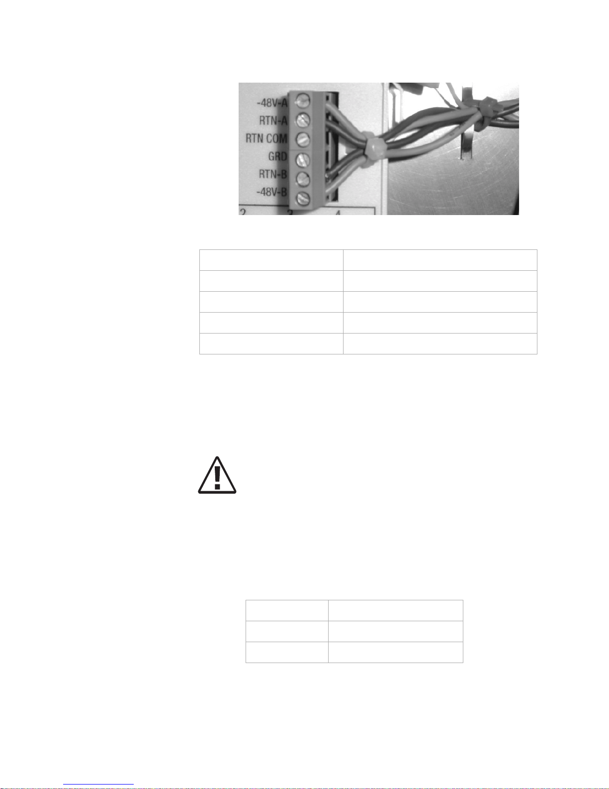
...........................................................................................................................................................................................................................................................
Equipment and Cable Installation for Metropolis
®
DMXplore Shelf (Wall-Mount)
Power Cable Installation
1-20
365-372-334 R2.0
Issue 4, November 2004
Figure 1-9 Power Connection
Table 1-4 Power Cable Color Coding
...........................................................................................................................................................................
Step 3 Route the power cables toward the power source (e.g. AC/DC
Converter, BDCBB, BDFB etc.)
Important! The Metropolis
®
DMXplore is powered by -48 V DC.
CAUTION
If using BBCBB or BDFB, verify that the BDCBB breakers ar e
off or that the BDFB fuses are not install ed.
...........................................................................................................................................................................
Step 4 Are you using an AC/DC Converter?
Color Coding Connection
Red -48V-A
Red/Black RTN-A
Blue -48V-B
Blue/Black RTN-B
IF... Then...
Yes Proceed to Step 5
No Proceed to Step 7
Page 63

Equipment and Cable Installation for Metropolis
®
DMXplore Sh elf (Wall-Mount)
Power Cable Installation
...........................................................................................................................................................................................................................................................
1-21
365-372-334 R2.0
Issue 4, November 2004
...........................................................................................................................................................................
Step 5 If not using the orderable AC/DC converter (C), verify that the
converter is fuse limited to 2-amperes on each lead.
Important! If the AC/DC converter is not fuse limited to 2-
amperes
, it will be necessary to add a 2A inline fuse for each power
lead.
...........................................................................................................................................................................
Step 6 Proceed to Step 9.
...........................................................................................................................................................................
Step 7 Splice feeders from the BDCBB or BDFB to the Metropolis
®
DMXplore power cables. Refer to Table 1-3, Power Connections (page
1-18).
Important! Four wires are spliced to the power cables:
1. BAT A
2. BAT A RTN
3. BAT B
4. BAT B RTN
...........................................................................................................................................................................
Step 8 Label the feeders at the power source as follows:
1. BAT A
2. BAT A RTN
3. BAT B
4. BAT B RTN
Important! Each feeder should be fused for 2-amperes.
...........................................................................................................................................................................
Step 9 Leave the power supply mechanism disconnected at the power source
until you are ready to perform the procedures in Chapter 3, Powering
and Initial Circuit Pack Installation for Metropolis
®
DMXplore Shelf
(Wall-Mount) of this manual.
Page 64

...........................................................................................................................................................................................................................................................
Equipment and Cable Installation for Metropolis
®
DMXplore Shelf (Wall-Mount)
Power Cable Installation
1-22
365-372-334 R2.0
Issue 4, November 2004
Important! The BDFB requires the removal of fuses to inhibit
power flow.
...........................................................................................................................................................................
Step 10 Check off the appropriate box in Appendix E, Installation Checklist.
End of Steps
...........................................................................................................................................................................
Page 65

Equipment and Cable Installation for Metropolis
®
DMXplore Sh elf (Wall-Mount)
DS1 Cable Installation
...........................................................................................................................................................................................................................................................
1-23
365-372-334 R2.0
Issue 4, November 2004
............................................................................................................................................................................................................................................................
DS1 Cable Installation
Description This section describes how to connect the DS1 transmission cables to
the A/D function group of the shelf. If applicable, route the cables out
of the bay and connect the cables to the DSX panel.
Important! When cabling the Metropolis
®
DMXplore to a DSX,
the DSX becomes an extension of the Metropolis® DMXplore
access panel connections. Thus the IN on the Metropolis
®
DMXplore access panel connects to the IN of the DSX and the
OUT of the Metropolis® DMXplore access panel connects to the
OUT of the DSX respectively.
The cables are connectorized at the Metropolis® DMXplore end and
may be needed to be wire-wrapped at the DSX end if equipped with a
blunt connection end. The A function group supports a maximum of 16
DS1 drop capacity.
Important! The A/D function group is a dual purpose slot. In the
current release the A/D slot is identified as the A function group.
Future releases will add new functionality and refer to the A/D slot
as the D function group.
Table 1-5, DS1 Cable Assemblies and Table 1-6, DS1 Transmission
Connections (page 1-24) lists the available DS1 cable assemblies and
DS1 connections, respectively.
Table 1-5 DS1 Cable Assemblies
Description Cabl e Length
(feet)
Cable
Assembly #
Single DS1 Cable, 26-gaug e,
RJ45-RJ45
8 109468124
20 109142398
50 109142406
100 109142414
150 109142422
250 109142430
350 109142448
550 109142455
Page 66

...........................................................................................................................................................................................................................................................
Equipment and Cable Installation for Metropolis
®
DMXplore Shelf (Wall-Mount)
DS1 Cable Installation
1-24
365-372-334 R2.0
Issue 4, November 2004
...........................................................................................................................................................................
Single DS1 Cable, 26-gaug e,
RJ45 blunt-cut
8 109468132
20 109142323
50 109142331
100 109142349
150 109142356
250 109142364
350 109142372
550 109142380
Bundle of 16 DS1 Cables, 26
gauge, RJ45 blunt-cut
20 109308437
50 109308445
100 109308452
150 109308460
250 109308478
350 109308486
550 109308494
Table 1-5 DS1 Cable Assemblies
Description Cabl e Length
(feet)
Cable
Assembly #
Table 1-6 DS1 Transmission Connections
Pin Tip/Ring
Designation
Direction Color
1Ring Out BL-W
2Tip Out W-BL
4Ring In O-W
5 Tip In W-O
Page 67
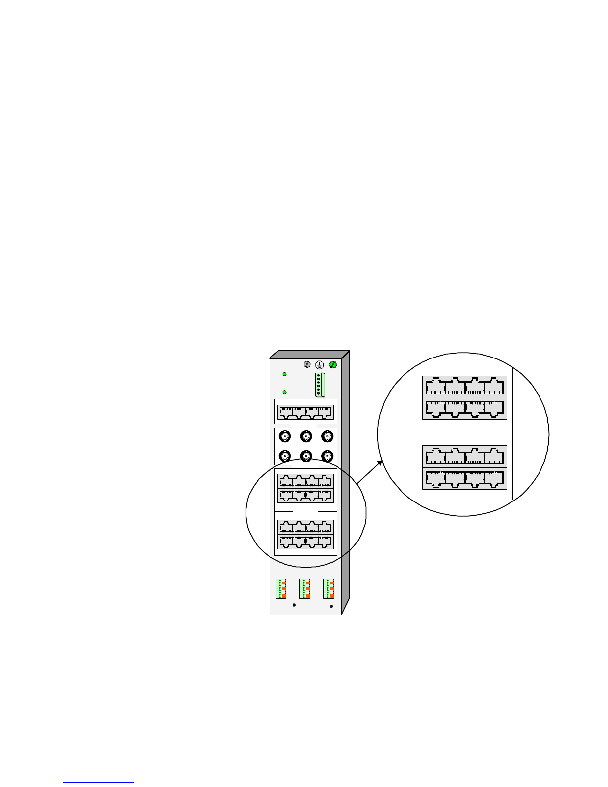
Equipment and Cable Installation for Metropolis
®
DMXplore Sh elf (Wall-Mount)
DS1 Cable Installation
...........................................................................................................................................................................................................................................................
1-25
365-372-334 R2.0
Issue 4, November 2004
Procedure
Step 1
Refer to the engineering job specification. Obtain the DS1 cables per
Table 1-5, DS1 Cable Assemblies (page 1-23). Label the cables,
indicating bay and shelf, and direction (IN or OUT of the bay) at each
end. See Table 1-6, DS1 Transmission Connections (page 1-24) for
associated color coding.
Important! Blunt-end cables that are to be wire wra pped will need
to be labeled IN or OUT. Cable ends terminated using a RJ-45
connector will not need to be labeled using the IN and OUT
designation because both are supported by the connector.
...........................................................................................................................................................................
Step 2 Connect the RJ-45 end of a single cable to the respective RJ-45
Receptacle on the access panel as shown in Figure 1-10, DS1 Access
Panel Cable Connectors (page 1-25).
Figure 1-10 DS1 Access Panel Cable Connectors
...........................................................................................................................................................................
Step 3 Route the cables along the access panel and out toward the DSX. See
Figure 1-11, DS1 Cable Routing (page 1-26)
ALARM
1
2
3
4
5
6
7
8
PWR-A
PWR-B
ON
ON
-48V-A
RTN-COM
-48V-B
RTN-B
RTN-A
GRD
41
81818181
23
C GROUP
123
B GROUP
RXTXRX
TX
81818181
81818181
3214
7658
A/D GRO UP
81818181
81818181
1110912
151413 16
1
2
3
4
5
6
7
8
1
2
3
4
5
6
7
8
MDOMDI
81818181
81818181
3214
7658
A/D GROUP
81818181
81818181
1110912
151413 16
Page 68
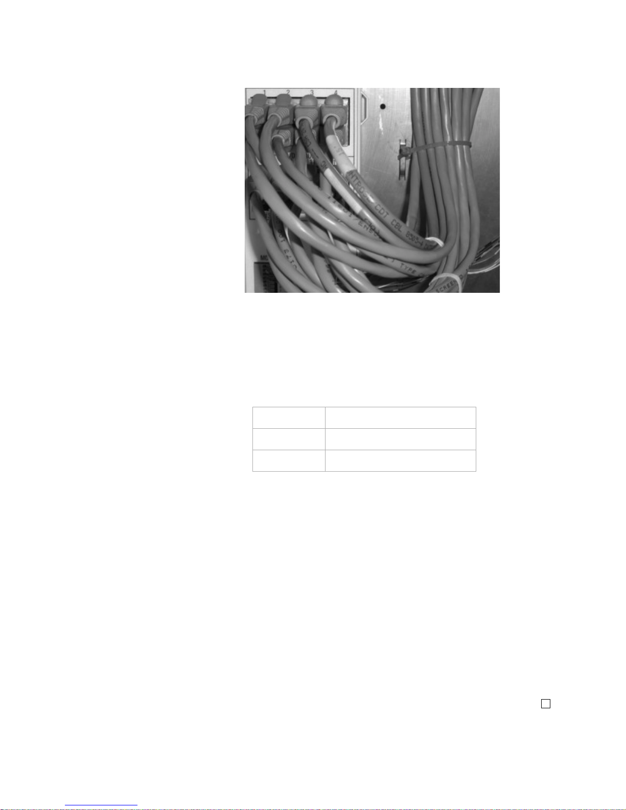
...........................................................................................................................................................................................................................................................
Equipment and Cable Installation for Metropolis
®
DMXplore Shelf (Wall-Mount)
DS1 Cable Installation
1-26
365-372-334 R2.0
Issue 4, November 2004
Figure 1-11 DS1 Cable Routing
...........................................................................................................................................................................
Step 4 Route the cables along the cable rack and into the terminating bay or
along the wall if mounting on a wall.
...........................................................................................................................................................................
Step 5 Are you terminating the DS1 cables on a DSX?
...........................................................................................................................................................................
Step 6 Remove slack and cut the DS1 cables to the desired length at the DSX.
...........................................................................................................................................................................
Step 7 Referring to Table 1-6, DS1 Transmission Connections (page 1-24),
carefully observe color codes and wire-wrap the cables at the DSX.
...........................................................................................................................................................................
Step 8 Check off the appropriate box in Appendix E, Installation Checklist.
End of Steps
...........................................................................................................................................................................
IF... Then...
Yes Go on to Step 6
No Skip to Step 8
Page 69

Equipment and Cable Installation for Metropolis
®
DMXplore Sh elf (Wall-Mount)
DS3 Cable Installation
...........................................................................................................................................................................................................................................................
1-27
365-372-334 R2.0
Issue 4, November 2004
............................................................................................................................................................................................................................................................
DS3 Cable Installation
Description This section describes how to connect the DS3 transmission cables to
the B function group of the shelf. If applicable, route the cables out of
the bay and connect the cables to the DSX panel.
Important! When cabling the Metropolis
®
DMXplore to a DSX,
the DSX becomes an extension of the Metropolis® DMXplore
access panel connections. Thus the IN on the Metropolis
®
DMXplore access panel connects to the IN of the DSX and the
OUT of the Metropolis® DMXplore access panel connects to the
OUT of the DSX, respectively.
The cables are connectorized at the Metropolis® DMXplore end and
will need to be connected to the appropriate BNC termination at the
other end. The B function group supports a maximum of two DS3 drop
capacity.
DS3 cable options are listed in T able 1-7, DS3 Cable Assemblies (page
1-27).
...........................................................................................................................................................................
Table 1-7 DS3 Cable Assemblies
Description Cable
Assembly #
Cable Length
(feet)
DS3 Cables, 735A coaxial,
Straight BNC (terminated)
plug to Straight BNC
(shipped loose) plug, 26
gauge
109468140 8
108785536 20
108785569 50
108785601 100
108785635 150
108785718 250
Notes:
1. One code provides one DS3 input and one DS3 output cable.
Page 70

...........................................................................................................................................................................................................................................................
Equipment and Cable Installation for Metropolis
®
DMXplore Shelf (Wall-Mount)
DS3 Cable Installation
1-28
365-372-334 R2.0
Issue 4, November 2004
Procedure
Step 1
Refer to the engineering job specification. Obtain the DS3 cables per
Table 1-7, DS3 Cable Assemblies and note the function group where
each cable will be used. Label the cables, indicating bay , shelf, function
group (B) and direction (IN or OUT of the bay) at each end.
...........................................................................................................................................................................
Step 2 C onnect one end of the cable to the respective Receptacle on the access
panel as shown in Figure 1-12, DS3 Access Panel Cable Connectors.
(page 1-28).
Figure 1-12 DS3 Access Panel Cable Connectors.
...........................................................................................................................................................................
Step 3 Route the cables along the cable rack and into the terminating bay or
along the wall if mounting on a wall.
...........................................................................................................................................................................
Step 4 Connect the cables to their respective positions on the terminating
equipment.
ALARM
1
2
3
4
5
6
7
8
PWR-A
PWR-B
ON
ON
-48V-A
RTN-COM
-48V-B
RTN-B
RTN-A
GRD
41
81818181
23
C GROUP
123
B GROUP
RX
TX
RX
TX
81818181
81818181
3214
7658
A/D GROUP
81818181
81818181
1110912
151413 16
1
2
3
4
5
6
7
8
1
2
3
4
5
6
7
8
MDOMDI
123
B GROUP
RX
TX
RX
TX
Page 71

Equipment and Cable Installation for Metropolis
®
DMXplore Sh elf (Wall-Mount)
DS3 Cable Installation
...........................................................................................................................................................................................................................................................
1-29
365-372-334 R2.0
Issue 4, November 2004
...........................................................................................................................................................................
Step 5 Check off the appropriate box in Appendix E, Installation Checklist.
End of Steps
Page 72

...........................................................................................................................................................................................................................................................
Equipment and Cable Installation for Metropolis
®
DMXplore Shelf (Wall-Mount)
Ethernet Cable Installation
1-30
365-372-334 R2.0
Issue 4, November 2004
............................................................................................................................................................................................................................................................
Ethernet Cable Installation
Overview This section describes how to route the Fast Ethernet (10/100Base T)
cables from the Wall-Mount Metropolis® DMXplore shelf to the
10/100BaseT terminating equipment.
If Fast Ethernet Cabling is not available yet, this section may be
completed later.
Procedure Refer to Figure 1-13, 10/100Base-T Cable Installation (page 1-31)
when performing this procedure.
Step 1 Obtain the 10/100BaseT cables per Table 1-8, LAN 10/100 BaseT
Cable Assemblies for Fast Ethernet
...........................................................................................................................................................................
Step 2 Connect one end of the cable to the respective RJ45 connecter on the
access panel on the rear of the Rack-Mount Metropolis® DMXplore
shelf.
...........................................................................................................................................................................
Step 3 Route the cables along the cable rack and into the terminating bay or
along the wall if mounting on a wall.
Page 73
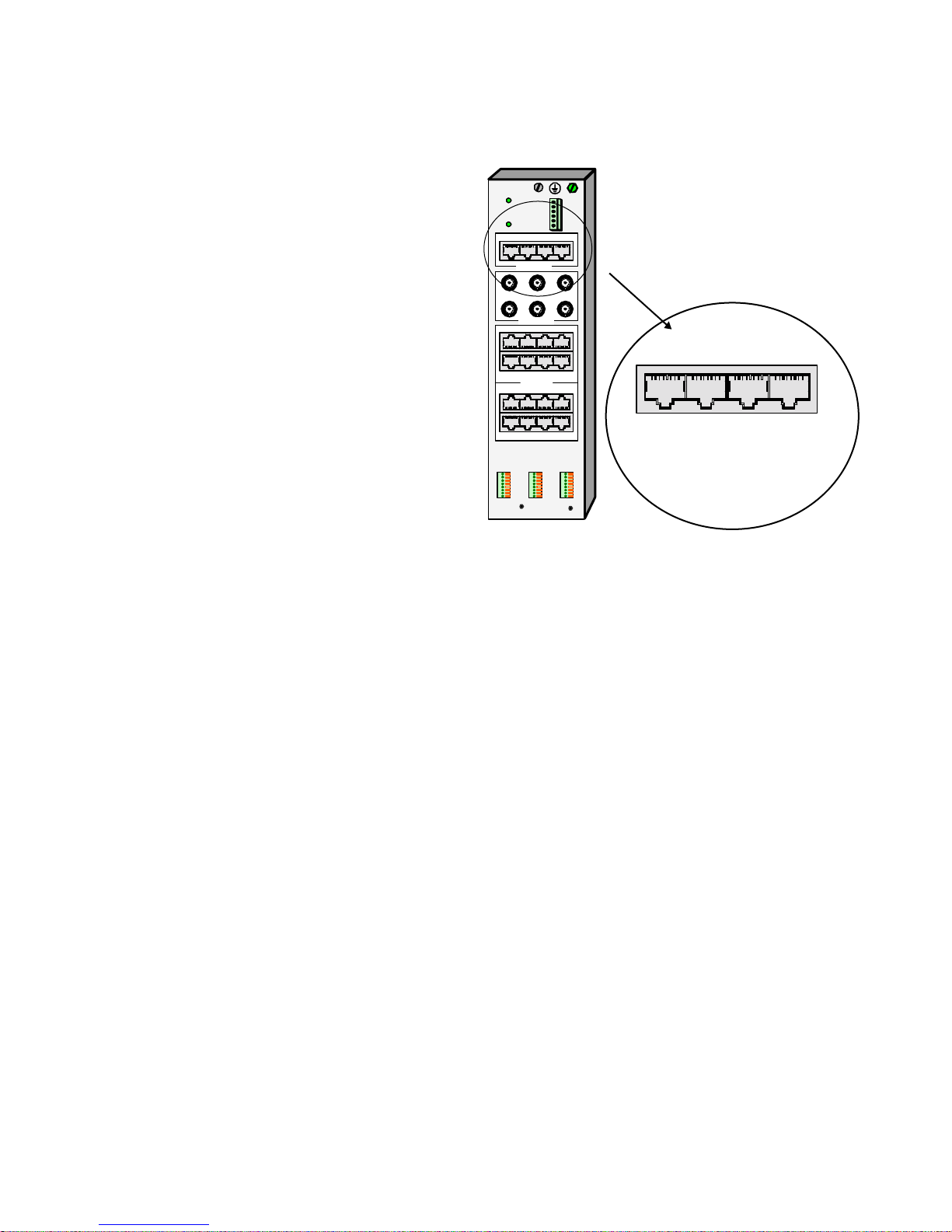
Equipment and Cable Installation for Metropolis
®
DMXplore Sh elf (Wall-Mount)
Ethernet Cable Installation
...........................................................................................................................................................................................................................................................
1-31
365-372-334 R2.0
Issue 4, November 2004
Figure 1-13 10/100Base-T Cable Installation
...........................................................................................................................................................................
Step 4 Label the cables, indicating bay (if required), shelf, pack and position
(1 through 4).
...........................................................................................................................................................................
Step 5 Connect the cables onto their respective positions at the 10/100BaseT
terminating equipment.
...........................................................................................................................................................................
Step 6 Check off the appropriate box in Appendix E, Installation Checklist.
ALARM
1
2
3
4
5
6
7
8
PWR-A
PWR-B
ON
ON
-48V-A
RTN-COM
-48V-B
RTN-B
RTN-A
GRD
41
1818181
23
C GROUP
123
B GROUP
RXTXRX
TX
81818181
81818181
3214
7658
A/D GROUP
81818181
81818181
1110912
151413 16
1
2
3
4
5
6
7
8
1
2
3
4
5
6
7
8
MDOMDI
41
1818181
23
C GRO UP
8
Page 74

...........................................................................................................................................................................................................................................................
Equipment and Cable Installation for Metropolis
®
DMXplore Shelf (Wall-Mount)
Ethernet Cable Installation
1-32
365-372-334 R2.0
Issue 4, November 2004
Table 1-8 LAN 10/100 BaseT Cable Assemblies for Fast Ethernet
Description Comcode Cable
Length (feet)
Metropolis
®
DMX
plore
Connections
LAN 10BaseT
Cross-over cable
RJ45 — RJ45
109154476 8
FASTE circuit pack
Ports 1 - 4
109142513
20
109142521
50
109142539
100
109142547
150
109142554
250
LAN 10BaseT
Straight-through cable
RJ45 — RJ45
109154468
8
109142463
20
109142471
50
109142489
100
109142497
150
109142505
250
Page 75

Equipment and Cable Installation for Metropolis
®
DMXplore Sh elf (Wall-Mount)
Office Alarm Cable Installation
...........................................................................................................................................................................................................................................................
1-33
365-372-334 R2.0
Issue 4, November 2004
............................................................................................................................................................................................................................................................
Office Alarm Cable Installation
Description Office alarms are the common method used in a central office for
maintenance personnel to quickly isolate a failure. Perform this
procedure if connection to the office alarm system is required.
Important! The office alarm relay contacts are rated at 50 VA
which means that they are capable of switching 1 amp at 50 volts,
or 2 amps at 25 volts. Their ability to switch lar ge tran sient currents
means that they can, if necessary, switch up to ten 5-watt aisle pilot
lamps.
If transient voltages or currents are above these limits, transient
noise-suppressing devices such as diodes or contact protection
networks must be used to keep within the voltage and current limits. If
these protection devices are not sufficient, an external buffer relay
MUST be provided.
In all cases, and as a matter of good practice, suppression devices such
as diodes or contact protection networks must be provided across any
external relay coil being driven by the Metropolis® DMXplore to limit
transient voltages and currents.
Office alarm cable assemblies are listed in Table 1-9, Office Alarm
Cable Assemblies (page 1-33) and Office alarm connection are listed in
Table 1-10, Office Alarm Connections (page 1-34).
Table 1-9 Office Alarm Cable Assemblies
Description
Cable
Assembly #
Cable
Length
(feet)
Access Panel
Connections
ALARM, 26 AWG, 8
conductors
848946653 30 ALARM
Notes:
1. Miscellaneous Discre te and Alarm cables are ide ntical and thus have the
same comcode.
Page 76

...........................................................................................................................................................................................................................................................
Equipment and Cable Installation for Metropolis
®
DMXplore Shelf (Wall-Mount)
Office Alarm Cable Installation
1-34
365-372-334 R2.0
Issue 4, November 2004
Procedure
Step 1
Obtain the office alarm cable per Table 1-9, Office Alarm Cable
Assemblies (page 1-33). Connect the office alarm cables to the
ALARM terminal block in the lower left hand corner of the access
panel. See Figure 1-14, Office Alarm Cable Connections (page 1-35)
Important! The recommended wire strip length for cables being
connected to the alarm block is 11mm.
Table 1-10 Office Alarm Connections
Pin# Color Name Designation
1
2
BL
BL/W
CR/MJ Visual +
CR/MJ Visual -
RYCRMJV1
3
4
O
O/W
CR/MJ Audible +
CR/MJ Audible -
RYCRMJA1
5
6
G
G/W
MN/ABN Visual +
MN/ABN Visual -
RYMNABNV1
7
8
BR
BR/W
MN/ABN Audible +
MN/ABN Audible -
RYMNABNA1
Notes:
1. The SYSCTL circuit pack reports office alarms.
Page 77

Equipment and Cable Installation for Metropolis
®
DMXplore Sh elf (Wall-Mount)
Office Alarm Cable Installation
...........................................................................................................................................................................................................................................................
1-35
365-372-334 R2.0
Issue 4, November 2004
Figure 1-14 Office Alarm Cable Connections
...........................................................................................................................................................................
Step 2 Route the office alarm cable to the office alarm panel. See Figure 1-17,
Miscellaneous Discretes and Office Alarm Cable Routing (page 1-40).
Important! Miscellaneous Discrete connections and Alarm
connections may be dressed together in a single bundle.
Figure 1-15 Alarm Cable Routing
...........................................................................................................................................................................
Step 3 Inspect the office alarm panel and add a contact protection network (if
required).
ALARM
1
2
3
4
5
6
7
8
PWR-A
PWR-B
ON
ON
-48 V -A
RTN-COM
-48 V -B
RTN-B
RTN-A
GRD
41
81818181
23
C GROUP
123
B GROUP
RX
TX
RX
TX
81818181
81818181
3214
7658
A/D GROUP
81818181
81818181
1110912
151413 16
1
2
3
4
5
6
7
8
1
2
3
4
5
6
7
8
MDOMDI
Page 78

...........................................................................................................................................................................................................................................................
Equipment and Cable Installation for Metropolis
®
DMXplore Shelf (Wall-Mount)
Office Alarm Cable Installation
1-36
365-372-334 R2.0
Issue 4, N ove m ber 2004
...........................................................................................................................................................................
Step 4 Cut the office alarm cable to the desired length.
...........................................................................................................................................................................
Step 5 Wire-wrap the loose end of the office alarm cable to the alarm panel,
making connections as listed in Table 1-10, Office Alarm Connections
(page 1-34).
...........................................................................................................................................................................
Step 6 Check off the appropriate box in Appendix E, Installation Checklist.
End of Steps
...........................................................................................................................................................................
Page 79

Equipment and Cable Installation for Metropolis
®
DMXplore Sh elf (Wall-Mount)
Miscellaneous (Environmental) Discrete
Telemetry Cable Installation
...........................................................................................................................................................................................................................................................
1-37
365-372-334 R2.0
Issue 4, November 2004
Miscellaneous (Environmental) Discrete Telemetry Cable
............................................................................................................................................................................................................................................................
Installation
Description The miscellaneous (environmental) discrete telemetry access all ows the
maintenance center to control and monitor equipment collocated with
the Metropolis® DMXplore.
The environmental control feature enables the maintenance center to
remotely initiate up to four contact clos ures at the remote t erminal (RT)
for equipment operation such as pumps, generators, etc.
The environmental alarm status indications allow up to 4 miscellaneous
user-settable alarm status indications (SI) at the remote terminal for
transmission toward the central office.
Miscellaneous (environmental) discrete telemetry cable assemblies and
connections are listed in Table 1-11, Miscellaneous Discrete Cable
Assemblies (page 1-37) and Table 1-12, Miscellaneous
(Environmental) Discrete Telemetry Connections (page 1-38),
respectively.
Table 1-11 Miscellaneous Discrete Cable Assemblies
Description
Cable
Assembly #
Cable
Length
(feet)
Access Panel
Connections
MDI, 26-gauge, 8
conductors
848946653 30 MDI
MDO, 26-gauge, 8
conductors
848946653 30 MDO
Notes:
1.
Miscellaneous Discrete and Alarm cables are identical and thus have the
same comcode.
Page 80

...........................................................................................................................................................................................................................................................
Equipment and Cable Installation for Metropolis
®
DMXplore Shelf (Wall-Mount)
Miscellaneous (Environmental) Discrete
Telemetry Cable Installation
1-38
365-372-334 R2.0
Issue 4, N ove m ber 2004
Important! Typically, the MDO (out) of the lowest Metropolis
®
DMXplore in a bay is connected to the patch panel and MDI (in) is
connected to the next higher Metropolis® DMXplore MDO.
...........................................................................................................................................................................
Procedure This procedure is performed for Metropolis
®
DMXplore shelves
requiring miscellaneous (environmental) discrete telemetry.
Step 1 Connect the miscellaneous discrete telemetry cables to the MDI and
MDO terminal blocks on the access panel of the Metropolis
®
DMXplore shelf per Figure 1-16, Miscellaneous Discrete Cable
Connection (page 1-39).
Table 1- 12 Miscellaneous (Environmental) Discrete Telemetry
Connections
Pin# Color Designation Name
1
2
3
4
BL
BL/W
O
O/W
Circuit #1 +
Circuit #1 Circuit #2 +
Circuit #2 -
Env. Input/Output - #1
Env. Input/Output - #2
Env. Input/Output - #3
Env. Input/Output - #4
5
6
7
8
G
G/W
BR
BR/W
Circuit #3 +
Circuit #3 Circuit #4 +
Circuit #4 -
Env. Input/Output - #5
Env. Input/Output - #6
Env. Input/Output - #7
Env. Input/Output - #8
Page 81

Equipment and Cable Installation for Metropolis
®
DMXplore Sh elf (Wall-Mount)
Miscellaneous (Environmental) Discrete
Telemetry Cable Installation
...........................................................................................................................................................................................................................................................
1-39
365-372-334 R2.0
Issue 4, November 2004
Figure 1-16 Miscellaneous Discrete Cable Connection
...........................................................................................................................................................................
Step 2 Route the miscellaneous (environmental) discretes cables to the
telemetry panel as shown in Figure 1-17, Miscellaneous Discretes and
Office Alarm Cable Routing (page 1-40).
Important! Miscellaneous Discrete connections and Alarm
connections may be dressed together in a single bundle.
ALARM
1
2
3
4
5
6
7
8
PWR-A
PWR-B
ON
ON
-48V-A
RTN-COM
-48V-B
RTN-B
RTN-A
GRD
41
81818181
23
C GROUP
123
B GROUP
RX
TX
RX
TX
81818181
81818181
3214
7658
A/D GRO UP
81818181
81818181
1110912
151413 16
1
2
3
4
5
6
7
8
1
2
3
4
5
6
7
8
MDOMDI
1
2
3
4
5
6
7
8
1
2
3
4
5
6
7
8
MDOMDI
Page 82
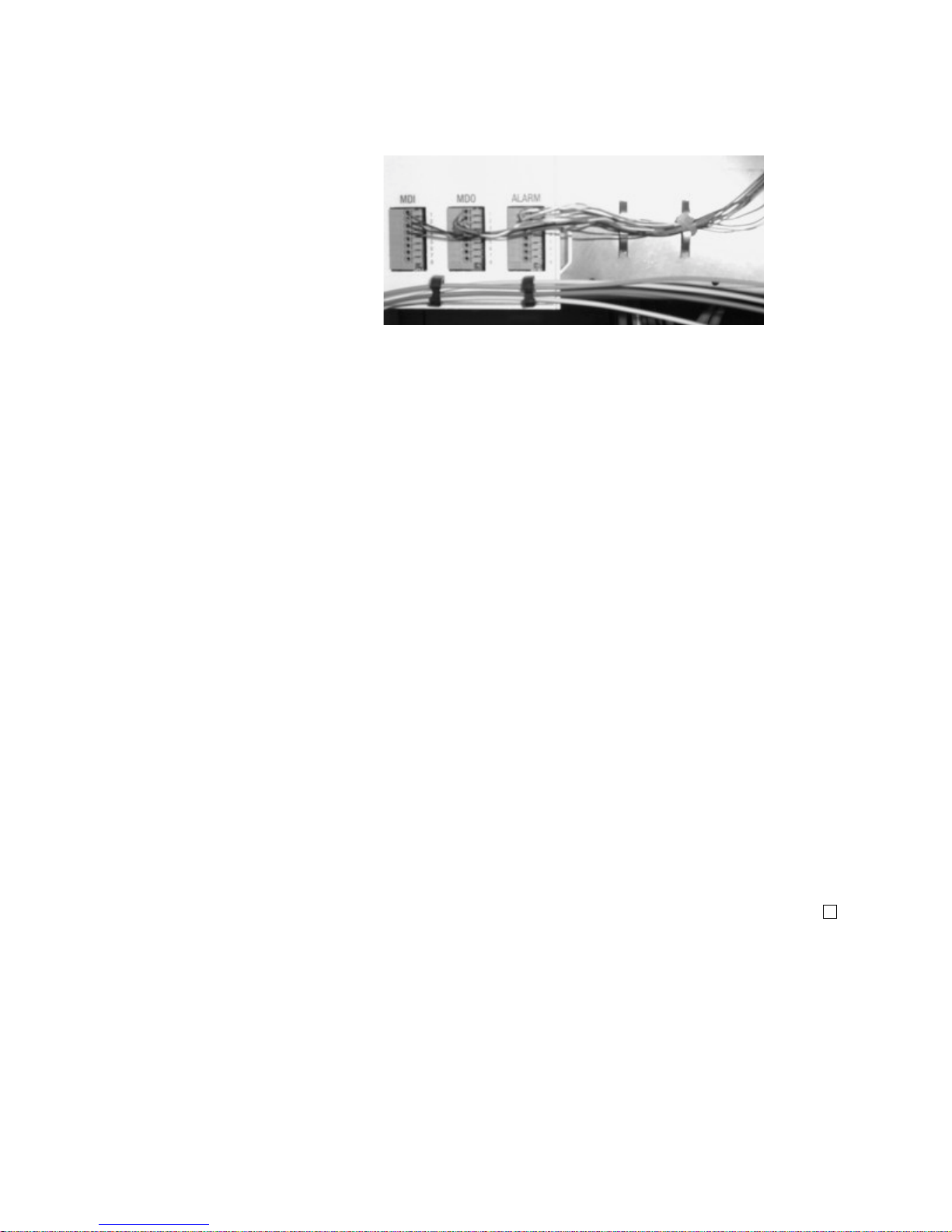
...........................................................................................................................................................................................................................................................
Equipment and Cable Installation for Metropolis
®
DMXplore Shelf (Wall-Mount)
Miscellaneous (Environmental) Discrete
Telemetry Cable Installation
1-40
365-372-334 R2.0
Issue 4, N ove m ber 2004
Figure 1-17 Miscellaneous Discretes and Office Ala rm Cable
Routing
...........................................................................................................................................................................
Step 3 Cut the miscellaneous (environmental) discrete telemetry cable to the
desired length at the telemetry panel.
...........................................................................................................................................................................
Step 4 Wire-wrap the loose end of the miscellaneous (environmental) discrete
telemetry cable to the wire-wrap terminal strip, making connections per
Table 1-12, Miscellaneous (Environmental) Discrete Telemetry
Connections (page 1-38).
Important! Each miscellaneous (environmental) discrete
telemetry designation is connected to the Metropolis® DMXplore
by two leads (wires). For each input, one lead should be connected
to input-common and the other lead should be connected to the
appropriate alarm indication. For each output, one lead should be
connected to output-common and the other lead should be
connected to the appropriate alarm indication.
...........................................................................................................................................................................
Step 5 Check off the appropriate box in Appendix E, Installation Checklist.
End of Steps
...........................................................................................................................................................................
Page 83

Equipment and Cable Installation for Metropolis
®
DMXplore Sh elf (Wall-Mount)
OC-3/OC12 Main Optical Fiber Cable
Installation
...........................................................................................................................................................................................................................................................
1-41
365-372-334 R2.0
Issue 4, November 2004
............................................................................................................................................................................................................................................................
OC-3/OC12 Main Optical Fiber Cable Installation
Description This section describes how to route the optical fiber cables from the
interconnecting equipment (for example, a LGX® optical fiber
distributing frame) to the Main OLIUs of the Metropolis® DMXplore.
This procedure does not cover routing the optical fiber cable between
sites.
The optical fiber cables are connected to the Metropolis® DMXplore
after the circuit packs are installed. The Metropolis® DMXplore
requires single-mode fiber for the main OLIUs. See ED8C947-10
Common Systems, Metropolis® DMXplore Access Multiplexer,
Engineering and Ordering Information for recommended fibers.
Important! The optical fiber cable is fragile and must be
protected. The fibers should be placed in a protective tube or
channel, such as PVC tubing, or PANDUIT cable channel, when
running the cable from the Metropolis® DMXplore to the cable
rack. The fibers should be placed in the cable rack in a protective
channel with nothing on top of them. Cable ties should NOT be
used with the optical fiber cables.
WARNING
Unterminated optical connectors may emit laser radiation. Do
not view an unterminated optical connector with optical
instruments. A void direct exposure o f the eyes to the beam.
Important! Prior to connecting the optical fiber cables, the fibers
should be examined to ensure that they are clean. See Appendix B,
Fiber Cleaning for recommended cleaning procedures.
...........................................................................................................................................................................
Page 84
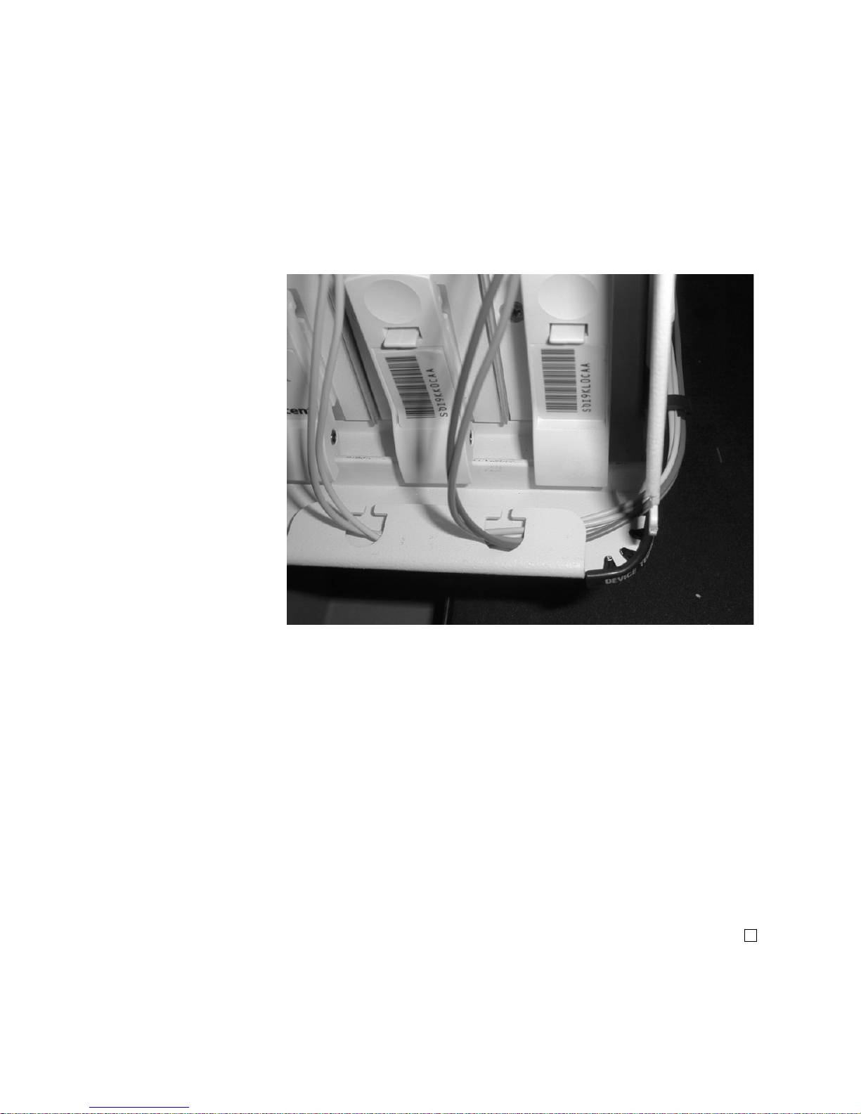
...........................................................................................................................................................................................................................................................
Equipment and Cable Installation for Metropolis
®
DMXplore Shelf (Wall-Mount)
OC-3/OC12 Main Optical Fiber Cable
Installation
1-42
365-372-334 R2.0
Issue 4, N ove m ber 2004
Procedure
Step 1
Route the optical fiber cables from the interconnecting equipment into
the left side of the Metropolis® DMXplore. See Figure 1-18, Optical
Fiber Routing (page 1-42)
Important! Protective covers must be left on cables.
Figure 1-18 Optical Fiber Routing
...........................................................................................................................................................................
Step 2 P lace the optical fiber cables in a protective tube or channel once it has
cleared the Metropolis® DMXplore shelf.
...........................................................................................................................................................................
Step 3 Label the optical fiber cables, indicating bay, shelf, pack, and direction
(IN or OUT). See Appendix F, Fiber Labeling for more details.
...........................................................................................................................................................................
Step 4 Check off the appropriate box in Appendix E, Installation Checklist.
End of Steps
...........................................................................................................................................................................
Page 85

Equipment and Cable Installation for Metropolis
®
DMXplore Sh elf (Wall-Mount)
RS-232 Serial CIT Cable Installation
...........................................................................................................................................................................................................................................................
1-43
365-372-334 R2.0
Issue 4, November 2004
............................................................................................................................................................................................................................................................
RS-232 Serial CIT Cable Installati on
Description This section provides the procedure to connect the CIT cable from the
VLNC1 (SYSCTL) to a PC (serial port) to allow communications
between the PC and the RS232 port located on the VLNC1.
CIT cable assemblies and the length options are listed in Table 1-13,
Serial CIT Cable Assembly (page 1-43). CIT cable connections are
listed in Table 1-14, Standard CIT Cable Connection (page 1-43) and
Table 1-15, RJ-45 to DB-9 Connector Connections (page 1-44).
Table 1-13 Serial CIT Cable Assembly
Table 1-14 Standard CIT Cable Connection
Description Cable
Assembly #
Cable
Length
Metropolis
®
DMX
plore
Connections
RS232 CIT
Cable
848748869 8 feet CIT/RS-232 jack on System
Controller (VLNC1)
Connection RJ45 connector Color 9-Pin D-type connector
Pin# Designation Pin# Designation
CIT cable 1 FRS232N W - O 6 DCE Ready
3 FDTR W - BL 4 DTE Ready
4 Ground W - G 5 Ground
5 FTXD O 2 Receive Data
6 FRXD G 3 Transmit Data
Notes:
1. The connection an d the col ors shown above are for a s tandard Lucent-made
cable. If you use a RJ-45 t o DB-9 connector with a standa rd straight-throu gh
10BASE-T LAN cable then, refer to Table 1-15, RJ-45 to DB-9 Connector
Connections (page 1-44).
Page 86

...........................................................................................................................................................................................................................................................
Equipment and Cable Installation for Metropolis
®
DMXplore Shelf (Wall-Mount)
RS-232 Serial CIT Cable Installation
1-44
365-372-334 R2.0
Issue 4, N ove m ber 2004
...........................................................................................................................................................................
Procedure
Step 1
Connect the RJ-45 end of the CIT cable to the RS232 jack located on
the VLNC1 (SYSCTL).
...........................................................................................................................................................................
Step 2 Connect the 9-pin D-type connector to the serial port on the PC.
...........................................................................................................................................................................
Step 3 Check off the appropriate box in Appendix E, Installation Checklist.
End of Steps
...........................................................................................................................................................................
Table 1-15 RJ-45 to DB-9 Connector Connections
From RJ45
connector
To DB-9 Pin D-type
connector
Pin# Color Pin#
1Blue 6
3Black 4
4Red 5
5 Green 2
6Yellow 3
Notes:
1. The connection and the colors shown above are for RJ-45 to DB9 connector.
2. This connector should be used with a standard straight-through
10BASE-T LAN cable.
Page 87

Equipment and Cable Installation for Metropolis
®
DMXplore Sh elf (Wall-Mount)
SYSCTL LAN Cable Installation
...........................................................................................................................................................................................................................................................
1-45
365-372-334 R2.0
Issue 4, November 2004
............................................................................................................................................................................................................................................................
SYSCTL LAN Cable Installation
Description This section describes how to connect the IAO LAN/TCP-IP (LAN
10BASE-T) cable to the Metropolis® DMXplore shelf and to the
interfacing equipment. Perform this procedure if this cabling is
required.
Metropolis® DMXplore supports an IntraOffice LAN (IAO LAN)
interface for operations data communications to support operations
systems such as the Navis Optical EMS (formerly WaveStar SNMS).
Since the IAO LAN can be provisioned as an extension of the SONET
DCC, the IAO LAN can also be used to join multiple, otherwise
separate subnetworks.
All NE-to-NE OI features that are supported over the DCC are also
supported over the IAO LAN.
The IAO LAN/TCP-IP interface cable is available in two
configurations (cross-over and straight-through) and is connected to the
front of the Metropolis® DMXplore shelf. The following tables provide
additional information:
• Table 1-16, LAN 10BASE-T Cable Assemblies (page 1-45)
• Table 1-17, LAN 10BASE-T Cross-over Cable Connections (page
1-47)
• Table 1-18, LAN 10BASE-T Straight-through Cable Connections
(page 1-47)
Table 1-16 LAN 10BASE-T Cable Assemblies
Description Cable
Assembly #
Cable
Length (feet)
LAN 10BASE-T
Cross-over (Cable to
PC / CIT)
109321810 10
848605028 50
848605036 100
848605051 150
848605064 200
848605077 300
Page 88

...........................................................................................................................................................................................................................................................
Equipment and Cable Installation for Metropolis
®
DMXplore Shelf (Wall-Mount)
SYSCTL LAN Cable Installation
1-46
365-372-334 R2.0
Issue 4, N ove m ber 2004
LAN 10BASE-T
Straight-through
(Cable to Ethernet
Hub / Router)
109321836 20
109321844 30
109321851 40
848604948 50
109321869 60
109321877 70
109321885 80
109321893 90
848604955 100
109321901 110
109321919 120
109321927 130
109321935 140
848604963 150
109321943 160
109321950 180
848604971 200
109321968 220
109321976 240
109321984 260
109321992 280
848604997 300
Table 1-16 LAN 10BASE-T Cable Assemblies
Description Cable
Assembly #
Cable
Length (feet)
Page 89

Equipment and Cable Installation for Metropolis
®
DMXplore Sh elf (Wall-Mount)
SYSCTL LAN Cable Installation
...........................................................................................................................................................................................................................................................
1-47
365-372-334 R2.0
Issue 4, November 2004
...........................................................................................................................................................................
Procedure
Step 1
Connect the cable to the LAN (RJ45) jack on the SYSCTL circuit pack.
Important! If connecting directly to a PC, use a LAN 10BASE-T
Cross-over Cable Assembly (See Table 1-16, LAN 10BASE-T Cable
Assemblies).
Important! If connecting to a hub, use a LAN 10BASE-T
Straight-through Cable Assembly (See Table 1-16, LAN 10BASE-T
Cable Assemblies).
Table 1- 17 LAN 10BASE-T Cross-over Cable Connections
SYSCTL
Connection
Metropolis
®
DMX
plore
Backplane
Color Other Side Design
LAN 1 BL - W 3 RDTR
2 W - BL 6 RS232N
3 O - W 1 RRXD
6W - O 2RTX
Table 1- 18 LAN 10BASE-T Straight-through Cable Connections
SYSCTL
Connection
Backplane Color Other Side
Pin
Designation
LAN 1 BL - W 1 XIOLANP
2 W - BL 2 X IOLANN
3 O - W 3 RIOLANP
6 W - O 6 RIOLANN
Page 90

...........................................................................................................................................................................................................................................................
Equipment and Cable Installation for Metropolis
®
DMXplore Shelf (Wall-Mount)
SYSCTL LAN Cable Installation
1-48
365-372-334 R2.0
Issue 4, N ove m ber 2004
...........................................................................................................................................................................
Step 2
...........................................................................................................................................................................
Step 3 Check off the appropriate box in Appendix E, Installation Checklist.
End of Steps
...........................................................................................................................................................................
Are you using... Then...
Cross-over LAN cable
Route the cable to the desired PC
LAN Network Interface card
Straight-through LAN cable
Route the cable to the desired hub
port location
Page 91

Equipment and Cable Installation for Metropolis
®
DMXplore Sh elf (Wall-Mount)
Final Operations
...........................................................................................................................................................................................................................................................
1-49
365-372-334 R2.0
Issue 4, November 2004
............................................................................................................................................................................................................................................................
Final Operations
Description Final check on equipment and cable installation.
...........................................................................................................................................................................
Procedure
Step 1
Verify that all the cables are properly dressed/connected.
...........................................................................................................................................................................
Step 2 Verify that all cables are properly labeled.
...........................................................................................................................................................................
Step 3 Verify that designations where cables were wire-wrapped are properly
labeled.
...........................................................................................................................................................................
Step 4 Verify that all the fibers are properly dressed/connected.
...........................................................................................................................................................................
Step 5 Verify that all fibers are properly labeled. See Appendix F, Fiber
Labeling
...........................................................................................................................................................................
Step 6 Verify that designations where fibers were terminated are properly
labeled.
...........................................................................................................................................................................
Step 7 Check off the appropriate box in Appendix E, Installation Checklist.
End of Steps
...........................................................................................................................................................................
Page 92

...........................................................................................................................................................................................................................................................
Equipment and Cable Installation for Metropolis
®
DMXplore Shelf (Wall-Mount)
Final Operations
1-50
365-372-334 R2.0
Issue 4, N ove m ber 2004
Page 93

2-1
365-372-334 R2.0
Issue 4, November 2004
............................................................................................................................................................................................................................................................
2 Equipment and Cable Installation
for Metropolis
®
DMXplore Shelf
(Rack-Mount)
............................................................................................................................................................................................................................................................
Overview
Purpose This section provides installation and cabling instructions for the
Metropolis® DMXplore Rack-Mount Shelf.
Mounting options for the Rack-Mount unit are:
1. Rear-mount with rear access
2. Front-mount with rear access
Important! The Rack-Mount Metropolis
®
DMXplore has an
integrated fan unit, and is stackable, up to 22 units may be installed
per 7 foot bay (no baffle is required).
Contents This chapter provides information on the following topics:
Overview 2-1
Planning 2-3
Connector References 2-7
Inspection 2-8
Metropolis
®
DMXplore Rack-Mount Shelf Installation 2-9
Power Cable Installation 2-13
DS1 Cable I nstallation 2-18
2-18
2-13
2-9
2-8
2-7
2-3
2-1
Page 94

...........................................................................................................................................................................................................................................................
Equipment and Cable Installation for Metropolis
®
DMXplore She lf (Rack -Mo un t)
Overview
2-2
365-372-334 R2.0
Issue 4, N ove m ber 2004
DS3 Cable I nstallation 2-22
Ethernet Cable Installation 2 -24
Office Alarm Cable Installation 2-26
Miscellaneous (Environmental) Discrete Telemetry Cable
Installation
2-29
OC-3/OC12 Main Optical Fiber Cable Installation 2-33
RS-232 Serial CIT Cable Installation 2-36
SYSCTL LAN Cable Install at ion 2-38
Final Operations 2-42
2-42
2-38
2-36
2-33
2-29
2-26
2-24
2-22
Page 95

Equipment and Cable Installation for Metropolis
®
DMXplore She lf (Rack- Mo un t)
Planning
...........................................................................................................................................................................................................................................................
2-3
365-372-334 R2.0
Issue 4, November 2004
............................................................................................................................................................................................................................................................
Planning
Description This section provides information about the following:
• tools, test equipment and accessories
• mounting options
• cabling checklist
...........................................................................................................................................................................
Tools, Test Equipment and
Accessories
Listed below are the tools, test equipment and accessories necessary to
perform the procedures in this section.
Quantity Description Comments
1 or 2
per shelf
AC/DC Wall-Mount/Rack
Bracket Mount Power
Converter
(408812394)
The AC/DC Wall-Mount converter allows the
Metropolis
®
DMXplore to be powered using a AC
voltage supply.
The acceptable AC input voltage
range for the AC/DC power supply is 85 VAC to
264V AC. This converter can be used with the
Rack-Mount Metropolis
®
DMXplore but it requires
a rack shelf / mounting arrangement (not provided
by Lucent).
1 3-prong power cord
Power cord is required to power the AC/DC WallMount power converter and is ordered separately.
Screwdriver(s) A screwdriver(s) with the appropriate head(s) is
(are) required for securing the mounting screws,
repositioning the mounting brackets, and installing
the interfacing cables.
1 RJ-45 Crimping tool
The crimping tool is required for terminating DS1
blunt-cut cables to a RJ-45 connector.
1 Wire-Wrap Gun
R-4496A
The wire-wrap gun is required for terminating DS1
cable and must be able to accommodate 24-gauge
wire.
1 ESD Wrist Strap
R-4987C
A wrist strap must be worn when handling circuit
packs. Use the electrostatic discharge (ESD) jack
provided on the shelf.
1 Torque Wrench
(R-5952)
A torque wrench (50-250 IN-LBS) is used when
tightening the Metropolis
®
DMXplore shelf to the
frame. It is also used when reattaching the mounting
brackets to the Metropolis
®
DMXplore shelf.
1 Torque Screwdriver A torque screwdriver is used to attach the 48 Volt
wiring to the terminal blo ck.
Page 96

...........................................................................................................................................................................................................................................................
Equipment and Cable Installation for Metropolis
®
DMXplore She lf (Rack -Mo un t)
Planning
2-4
365-372-334 R2.0
Issue 4, N ove m ber 2004
1 Metric & Inch Series Tool
Set
R - 6001
Because some Optical Networking Products (also
know as Trans port) may ha ve some metr ic fastener s,
please ensure that the proper metric tools are
available.
1 Multimeter ( Optional)
ITE-6379C
The voltmeter must be capable of measuring DC
voltage in the 40 to 60 volt range. The use of the
voltmeter is optional since the shelf will alarm or
shut down if the proper voltage is not supplied.
1Ohmmeter
ITE-6379C
An ohmmeter is required to verify that the
Metropolis
®
DMXplore is properly grounded.
Quantity Description Comments
Page 97

Equipment and Cable Installation for Metropolis
®
DMXplore She lf (Rack- Mo un t)
Planning
...........................................................................................................................................................................................................................................................
2-5
365-372-334 R2.0
Issue 4, November 2004
Mounting options The Rack-Mount mounting brackets for the Metropolis
®
DMXplore
Access Multiplexer are adjustable and designed to allow for mounting
in the following:
• 19-inch bay-frames
• Standard 23-inch wide network bay-frames
The recommended network bay-frames are the ED-8C500-50 and
the ED-8C501-50 (also allows for rear access).
• 23-inch seismic network bay-frame
The ED-8C800-50 and ED-8C801-50 seismic network bay-frames
are designed for use in all earthquake zones, and in general, do not
require top support at the 7-foot level. These frames meet Pacific
Bell Equipment Framework Standard PBS-000-102PT.
• 23-inch wide EIA-Type bay-frames
Cabling checklist This section briefly describes cabling information, including the
number of particular cables required. For information regarding
available cable lengths and ordering comcodes, refer to the tables in
this chapter.
Table 2-1, Cable Requirements and Options lists available cables along
with the required number (if any).
Table 2-1 Cable Requirements and Options
Notes:
1. One -48VA and -48VB main power feeder is required per shelf. Each
power feed needs to have an external 2A fuse.
2. One CIT Cable Assembly is required for PC serial interface with the
Cable Assembly Description Required See Note
Power Yes 1
CIT
Yes 2
LAN 10BASE-T (Cross-over)
LAN 10BASE-T (Straight-
Through)
DS1 Optional 3
DS3 Optional 4
Office Alarm Optional 5
Miscellaneous Discrete Optional
Page 98

...........................................................................................................................................................................................................................................................
Equipment and Cable Installation for Metropolis
®
DMXplore She lf (Rack -Mo un t)
Planning
2-6
365-372-334 R2.0
Issue 4, N ove m ber 2004
Metropolis® DMXplore (not included with equipment).
3. One "Single DS1 Cable Assembl y" is require d for each DS1 s upported by
the main pack (maximum of 16). Each DS1 Cable Assembly supports 1
pair of 24-gauge RJ45/blunt-cut or RJ45-RJ45 cables. One cable is for
input and output signals.
4. One "Single DS3 Cable Assembl y" is require d for each DS3 s upported by
the main pack. One code provides 1 DS3 input and 1 DS3 output, 735A
coaxial Straight BNC plug to Straight BNC plug.
5. When cabling the Metropolis
®
DMXplore for office alarm applications,
one Office Alarm Cable Assembly is required for each Metropolis
®
DMXplore shelf.
6. When accessing the shelf through the LAN (OSI/TCP-IP) connection,
either a LAN 10BASE-T cross- over cable or a LAN 10BASE-T strai ght through cable is requ ired to acc ess the shel f. The cross- over cable should
be used when connecting directly between the shelf from a PC NIC car d.
The straight-th rou gh c abl e s hould be used when connec ti ng the shelf to a
hub.
...........................................................................................................................................................................
Page 99

Equipment and Cable Installation for Metropolis
®
DMXplore She lf (Rack- Mo un t)
Connector References
...........................................................................................................................................................................................................................................................
2-7
365-372-334 R2.0
Issue 4, November 2004
............................................................................................................................................................................................................................................................
Connector References
Description Figure 2-1, Connector Types and Pinouts (page 2-7) provides the
pinouts of some of the connectors used to interface with the
Metropolis® DMXplore.
Figure 2-1 Connector Types and Pinouts
123
B GROUP
RX
TX
RX
TX
BNC
Connector
Page 100

...........................................................................................................................................................................................................................................................
Equipment and Cable Installation for Metropolis
®
DMXplore She lf (Rack -Mo un t)
Inspection
2-8
365-372-334 R2.0
Issue 4, N ove m ber 2004
............................................................................................................................................................................................................................................................
Inspection
Description Perform the following procedure before installing the Metropolis
®
DMXplore shelf and cables.
...........................................................................................................................................................................
Procedure
Step 1
Inspect the shelf for visible damage including bent or touching
backplane pins.
If any backplane pins are damaged, refer to Appendix D, Backplane Pin
Replacement for instructions on repairing the damaged pin(s).
...........................................................................................................................................................................
Step 2 Each Rack-Mount Metropolis
®
DMXplore shelf comes with a bag
containing the following items:
Verify that the bag is available and contains the items listed above.
...........................................................................................................................................................................
Step 3 Check off the appropriate box in Appendix E, Installation Checklist.
End of Steps
...........................................................................................................................................................................
Quantity Description
4 Screws for mounting the brackets to the shelf
4 Screws for mounti ng the shelf to the bay frame
1 Set of adjustable mounting brackets
1 Fiber Management Module
1 Safety Instruction Sheet
 Loading...