

Page 1

TM TM
Lucent Cajun
A500 ATM Switch
User Guide Release
3.0
Part #: 49080007
Page 2

Cajun A500 ATM Switch Installation Guide
© Copyright LUCENT TECHNOLOGIES 1999 ALL RIGHTS RESERVED
Printed in USA, April 1999
The products, specifications, and other technical information regarding the products contained in this
document are subject to change without notice. All information in this document is believed to be accurate
and reliable, but is presented without warranty of any kind, express or implied, and users must take full
responsibility for their application of any products specified in this document. Lucent disclaims
responsibility for errors which may appear in this document, and it reserves the right, in its sole discretion
and without notice, to make substitutions and modifications in the products and practices described in this
document.
Cajun P550, Cajun A500, Lucent Definity ATM ECS, and Lucent MMCX are trademarks of Lucent
T echnologies. The following products are trademaked by their respective companies: Bay Networks, Cisco,
Fore, 3COM, Sun, HP, Compaq, and Microsoft.
All other trademarks mentioned in this document are property of their respective owners.
Part Number 49080007 Revision 3
Cajun A500 Software Release 3.00
Page 3

Preface
Chapter 1 Cajun A500 ATM Switch Overview
Contents
Overview
Interoperability . . . . . . . . . . . . . . . . . . . . . . . . . . . . . . . . . . . . . . . . . . . . . . . . . . . . . . . . .1 - 1
Product Features . . . . . . . . . . . . . . . . . . . . . . . . . . . . . . . . . . . . . . . . . . . . . . . . . . . . . . . . 1 - 2
Cajun A500 Software . . . . . . . . . . . . . . . . . . . . . . . . . . . . . . . . . . . . . . . . . . . . . . . . . . . . . . .1 - 3
Data Flow . . . . . . . . . . . . . . . . . . . . . . . . . . . . . . . . . . . . . . . . . . . . . . . . . . . . . . . . . . . . .1 - 5
PNNI Routing Task . . . . . . . . . . . . . . . . . . . . . . . . . . . . . . . . . . . . . . . . . . . . . . . . . . . . . .1 - 6
ILMI Task . . . . . . . . . . . . . . . . . . . . . . . . . . . . . . . . . . . . . . . . . . . . . . . . . . . . . . . . . . . . .1 - 6
Call Control Task . . . . . . . . . . . . . . . . . . . . . . . . . . . . . . . . . . . . . . . . . . . . . . . . . . . . . . . .1 - 6
UNI/PNNI Signalling Task . . . . . . . . . . . . . . . . . . . . . . . . . . . . . . . . . . . . . . . . . . . . . . . . . 1 - 6
Internal Static IP Connectivity . . . . . . . . . . . . . . . . . . . . . . . . . . . . . . . . . . . . . . . . . . . . . 1 - 7
Static IP Architecture . . . . . . . . . . . . . . . . . . . . . . . . . . . . . . . . . . . . . . . . . . . . . . . . . . . . 1 - 8
SWP Operating System API . . . . . . . . . . . . . . . . . . . . . . . . . . . . . . . . . . . . . . . . . . . . . .1 - 10
Process Communication . . . . . . . . . . . . . . . . . . . . . . . . . . . . . . . . . . . . . . . . . . . . . . . . . . . .1 - 11
pSOSystem Operating System . . . . . . . . . . . . . . . . . . . . . . . . . . . . . . . . . . . . . . . . . . . . . . .1 - 11
pSOSystem Architecture . . . . . . . . . . . . . . . . . . . . . . . . . . . . . . . . . . . . . . . . . . . . . . . . . 1 - 11
Clock Synchronization . . . . . . . . . . . . . . . . . . . . . . . . . . . . . . . . . . . . . . . . . . . . . . . . . . . . .1 - 12
Connection Admission Control (CAC) . . . . . . . . . . . . . . . . . . . . . . . . . . . . . . . . . . . . . . . . .1 - 13
PNNI Functionality . . . . . . . . . . . . . . . . . . . . . . . . . . . . . . . . . . . . . . . . . . . . . . . . . . . . . . . .1 - 13
Peer Groups . . . . . . . . . . . . . . . . . . . . . . . . . . . . . . . . . . . . . . . . . . . . . . . . . . . . . . . . . . .1 - 13
Point to Point Protocol (PPP) . . . . . . . . . . . . . . . . . . . . . . . . . . . . . . . . . . . . . . . . . . . . . . . .1 - 14
Point-to-Point Protocol (PPP) Functionality . . . . . . . . . . . . . . . . . . . . . . . . . . . . . . . . . . . . . 1 - 15
About IP addresses . . . . . . . . . . . . . . . . . . . . . . . . . . . . . . . . . . . . . . . . . . . . . . . . . . . . . 1 - 16
Modem Connections . . . . . . . . . . . . . . . . . . . . . . . . . . . . . . . . . . . . . . . . . . . . . . . . . . . .1 - 16
Authentication Configuration . . . . . . . . . . . . . . . . . . . . . . . . . . . . . . . . . . . . . . . . . . . . . . . . 1 - 19
Password Authentication Protocol (PAP) . . . . . . . . . . . . . . . . . . . . . . . . . . . . . . . . . . . .1 - 20
Challenge-Handshake Authentication Protocol (CHAP) . . . . . . . . . . . . . . . . . . . . . . . .1 - 20
Data Flow . . . . . . . . . . . . . . . . . . . . . . . . . . . . . . . . . . . . . . . . . . . . . . . . . . . . . . . . . . . .1 - 21
. . . . . . . . . . . . . . . . . . . . . . . . . . . . . . . . . . . . . . . . . . . . . . . . . . . . . . . . . . . . . . . . .1 - 1
Chapter 2 Using the Cajun A500 Manager
Overview . . . . . . . . . . . . . . . . . . . . . . . . . . . . . . . . . . . . . . . . . . . . . . . . . . . . . . . . . . . . . . . . . 2 - 1
Logging In to the Web Agent . . . . . . . . . . . . . . . . . . . . . . . . . . . . . . . . . . . . . . . . . . . . . .2 - 1
Installing Cajun A500 Help Files . . . . . . . . . . . . . . . . . . . . . . . . . . . . . . . . . . . . . . . . . . . . . .2 - 2
Entering the Server Location . . . . . . . . . . . . . . . . . . . . . . . . . . . . . . . . . . . . . . . . . . . . . .2 - 3
Getting Updated Help Files on the Internet . . . . . . . . . . . . . . . . . . . . . . . . . . . . . . . . . . .2 - 4
Using the Cajun A500 Manager Web Agent . . . . . . . . . . . . . . . . . . . . . . . . . . . . . . . . . . . . . .2 - 5
Entering Basic System Information . . . . . . . . . . . . . . . . . . . . . . . . . . . . . . . . . . . . . . . . . . . .2 - 7
Changing Addresses . . . . . . . . . . . . . . . . . . . . . . . . . . . . . . . . . . . . . . . . . . . . . . . . . . . . . 2 - 7
Cajun A500 ATM Switch User Guide
iii
Page 4

Chapter 3 Configuring the Cajun A500 Network
Overview . . . . . . . . . . . . . . . . . . . . . . . . . . . . . . . . . . . . . . . . . . . . . . . . . . . . . . . . . . . . . . 3 - 1
Determining Your Network Configuration . . . . . . . . . . . . . . . . . . . . . . . . . . . . . . . . . . . . 3 - 1
Configuring the Link Types for the Cajun A500 . . . . . . . . . . . . . . . . . . . . . . . . . . . . . . . . 3 - 2
Guidelines for Determining the Link Type . . . . . . . . . . . . . . . . . . . . . . . . . . . . . . . . .3 - 2
Bringing the ATM Port Down . . . . . . . . . . . . . . . . . . . . . . . . . . . . . . . . . . . . . . . . . . . . . .3 - 3
Configuring/Modifying the Link Type . . . . . . . . . . . . . . . . . . . . . . . . . . . . . . . . . . . . . . .3 - 3
Bringing the ATM Port Up . . . . . . . . . . . . . . . . . . . . . . . . . . . . . . . . . . . . . . . . . . . . . . . . 3 - 4
Static Route Configuration . . . . . . . . . . . . . . . . . . . . . . . . . . . . . . . . . . . . . . . . . . . . . . . .3 - 4
Configuring Static Routes . . . . . . . . . . . . . . . . . . . . . . . . . . . . . . . . . . . . . . . . . . . . . . . . .3 - 5
Deleting a Static Route . . . . . . . . . . . . . . . . . . . . . . . . . . . . . . . . . . . . . . . . . . . . . . . . 3 - 5
Adding End Station Identifiers . . . . . . . . . . . . . . . . . . . . . . . . . . . . . . . . . . . . . . . . . . . . . 3 - 6
Deleting End Station Identifiers . . . . . . . . . . . . . . . . . . . . . . . . . . . . . . . . . . . . . . . . . 3 - 6
Configuring Permanent Virtual Channels and Paths . . . . . . . . . . . . . . . . . . . . . . . . . . . . 3 - 7
Adding Virtual Channels or Paths . . . . . . . . . . . . . . . . . . . . . . . . . . . . . . . . . . . . . . . .3 - 7
Deleting Virtual Channels or Paths . . . . . . . . . . . . . . . . . . . . . . . . . . . . . . . . . . . . . . . 3 - 8
Configuring LAN Emulation Client (LEC) Services . . . . . . . . . . . . . . . . . . . . . . . . . . . . .3 - 9
Static IP Connectivity . . . . . . . . . . . . . . . . . . . . . . . . . . . . . . . . . . . . . . . . . . . . . . . . . . . .3 - 9
Static IP Server . . . . . . . . . . . . . . . . . . . . . . . . . . . . . . . . . . . . . . . . . . . . . . . . . . . . . . 3 - 9
Hijacking the Ethernet Port . . . . . . . . . . . . . . . . . . . . . . . . . . . . . . . . . . . . . . . . . 3 - 10
Ethernet Filtering in Promiscuous Mode . . . . . . . . . . . . . . . . . . . . . . . . . . . . . .3 - 10
Configuring Static IP . . . . . . . . . . . . . . . . . . . . . . . . . . . . . . . . . . . . . . . . . . . . . . . . . . . . 3 - 10
Adding Static IP Clients and Servers . . . . . . . . . . . . . . . . . . . . . . . . . . . . . . . . . . . . . 3 - 11
Configuring Private Network-to-Network Interface (PNNI) . . . . . . . . . . . . . . . . . . . . . .3 - 11
Configuring Point-to-Point Protocol (PPP) . . . . . . . . . . . . . . . . . . . . . . . . . . . . . . . . . . .3 - 12
Configuring PPP Authentication . . . . . . . . . . . . . . . . . . . . . . . . . . . . . . . . . . . . . . . . 3 - 12
Configuring PPP Modem Scripts . . . . . . . . . . . . . . . . . . . . . . . . . . . . . . . . . . . . . . . .3 - 13
Configuring Operations Administration and Maintenance (OAM) . . . . . . . . . . . . . . . .3 - 13
Setting Up SNMP Communities . . . . . . . . . . . . . . . . . . . . . . . . . . . . . . . . . . . . . . . . . . .3 - 14
Configuring Clock Synchronization . . . . . . . . . . . . . . . . . . . . . . . . . . . . . . . . . . . . . . . .3 - 14
Setting Up the TFTP Server . . . . . . . . . . . . . . . . . . . . . . . . . . . . . . . . . . . . . . . . . . . . . . .3 - 15
Chapter 4 Managing the Physical Network
Overview . . . . . . . . . . . . . . . . . . . . . . . . . . . . . . . . . . . . . . . . . . . . . . . . . . . . . . . . . . . . . . 4 - 1
Saving and Restoring Configuration Parameters . . . . . . . . . . . . . . . . . . . . . . . . . . . . . . .4 - 1
Resetting the Cajun A500 ATM Switch . . . . . . . . . . . . . . . . . . . . . . . . . . . . . . . . . . . . . .4 - 2
Viewing and Changing the Cajun A500 System Status . . . . . . . . . . . . . . . . . . . . . . . . . .4 - 2
Viewing System Status Information . . . . . . . . . . . . . . . . . . . . . . . . . . . . . . . . . . . . . . . . .4 - 3
Viewing Module Information . . . . . . . . . . . . . . . . . . . . . . . . . . . . . . . . . . . . . . . . . . . . . .4 - 3
Viewing Current System Users . . . . . . . . . . . . . . . . . . . . . . . . . . . . . . . . . . . . . . . . . . . . .4 - 3
Viewing Address Information . . . . . . . . . . . . . . . . . . . . . . . . . . . . . . . . . . . . . . . . . . . . . .4 - 4
Viewing Event and Alarm Logs . . . . . . . . . . . . . . . . . . . . . . . . . . . . . . . . . . . . . . . . . . . . .4 - 4
Viewing Statistics . . . . . . . . . . . . . . . . . . . . . . . . . . . . . . . . . . . . . . . . . . . . . . . . . . . . . . .4 - 4
Viewing Port Statistics . . . . . . . . . . . . . . . . . . . . . . . . . . . . . . . . . . . . . . . . . . . . . . . . .4 - 4
Viewing the Signaling Summary Information . . . . . . . . . . . . . . . . . . . . . . . . . . . . . .4 - 5
Viewing Virtual Circuit Information . . . . . . . . . . . . . . . . . . . . . . . . . . . . . . . . . . . . . . . . . 4 - 5
Viewing Signaling Information . . . . . . . . . . . . . . . . . . . . . . . . . . . . . . . . . . . . . . . . . . . . .4 - 6
Viewing Signaling Cause Codes . . . . . . . . . . . . . . . . . . . . . . . . . . . . . . . . . . . . . . . . .4 - 6
iv Cajun A500 ATM Switch User Guide
Page 5

Viewing Signaling Statistics . . . . . . . . . . . . . . . . . . . . . . . . . . . . . . . . . . . . . . . . . . . . . . .4 - 6
Viewing LAN Emulation Client (LEC) Status . . . . . . . . . . . . . . . . . . . . . . . . . . . . . . . . . .4 - 7
Viewing LEC Configuration Information . . . . . . . . . . . . . . . . . . . . . . . . . . . . . . . . . . . . .4 - 7
Viewing Static IP Information . . . . . . . . . . . . . . . . . . . . . . . . . . . . . . . . . . . . . . . . . . . . . .4 - 8
Viewing Static IP Configuration Information . . . . . . . . . . . . . . . . . . . . . . . . . . . . . . .4 - 8
Viewing Static IP Client Information . . . . . . . . . . . . . . . . . . . . . . . . . . . . . . . . . . . . .4 - 8
Viewing Static IP Server Information . . . . . . . . . . . . . . . . . . . . . . . . . . . . . . . . . . . . .4 - 9
Viewing Point-to-Point Protocol (PPP) Information . . . . . . . . . . . . . . . . . . . . . . . . . . . . .4 - 9
Viewing OAM Information . . . . . . . . . . . . . . . . . . . . . . . . . . . . . . . . . . . . . . . . . . . . . . . . 4 - 9
Viewing Clock Sync Information . . . . . . . . . . . . . . . . . . . . . . . . . . . . . . . . . . . . . . . . . . 4 - 10
Chapter 5 Using the Cajun A500 Command Line Interface
Overview . . . . . . . . . . . . . . . . . . . . . . . . . . . . . . . . . . . . . . . . . . . . . . . . . . . . . . . . . . . . . . 5 - 1
Accessing the Cajun A500 Console . . . . . . . . . . . . . . . . . . . . . . . . . . . . . . . . . . . . . . . . . .5 - 2
Commands . . . . . . . . . . . . . . . . . . . . . . . . . . . . . . . . . . . . . . . . . . . . . . . . . . . . . . . . . . . . 5 - 2
Using a ? in a Command Line Sequence . . . . . . . . . . . . . . . . . . . . . . . . . . . . . . . . .5 - 2
Command Line Editing Options . . . . . . . . . . . . . . . . . . . . . . . . . . . . . . . . . . . . . . . . . . . .5 - 4
Understanding the Command Line Format . . . . . . . . . . . . . . . . . . . . . . . . . . . . . . . .5 - 4
Syntax Conventions . . . . . . . . . . . . . . . . . . . . . . . . . . . . . . . . . . . . . . . . . . . . . . .5 - 4
Command Line Entry Conventions . . . . . . . . . . . . . . . . . . . . . . . . . . . . . . . . . . .5 - 5
Syntax Structure . . . . . . . . . . . . . . . . . . . . . . . . . . . . . . . . . . . . . . . . . . . . . . . . . .5 - 5
Command Line Prompts . . . . . . . . . . . . . . . . . . . . . . . . . . . . . . . . . . . . . . . . . . . . . . .5 - 5
Supported User Accounts . . . . . . . . . . . . . . . . . . . . . . . . . . . . . . . . . . . . . . . . . . . . . .5 - 6
Modifying the root Password . . . . . . . . . . . . . . . . . . . . . . . . . . . . . . . . . . . . . . . . . . .5 - 6
Telnet Capabilities . . . . . . . . . . . . . . . . . . . . . . . . . . . . . . . . . . . . . . . . . . . . . . . . . . . . . . . 5 - 7
TFTP Capabilities . . . . . . . . . . . . . . . . . . . . . . . . . . . . . . . . . . . . . . . . . . . . . . . . . . . . . 5 - 7
Chapter 6 admin Commands
Overview . . . . . . . . . . . . . . . . . . . . . . . . . . . . . . . . . . . . . . . . . . . . . . . . . . . . . . . . . . . . . . 6 - 1
Subcommands . . . . . . . . . . . . . . . . . . . . . . . . . . . . . . . . . . . . . . . . . . . . . . . . . . . . . . . . . . 6 - 1
admin ack_alarms . . . . . . . . . . . . . . . . . . . . . . . . . . . . . . . . . . . . . . . . . . . . . . . . . . . . . . .6 - 4
admin address . . . . . . . . . . . . . . . . . . . . . . . . . . . . . . . . . . . . . . . . . . . . . . . . . . . . . . . . . . 6 - 5
admin changename . . . . . . . . . . . . . . . . . . . . . . . . . . . . . . . . . . . . . . . . . . . . . . . . . . . . . .6 - 6
admin changeboot . . . . . . . . . . . . . . . . . . . . . . . . . . . . . . . . . . . . . . . . . . . . . . . . . . . . . .6 - 7
admin changeprompt . . . . . . . . . . . . . . . . . . . . . . . . . . . . . . . . . . . . . . . . . . . . . . . . . . . .6 - 8
admin contact . . . . . . . . . . . . . . . . . . . . . . . . . . . . . . . . . . . . . . . . . . . . . . . . . . . . . . . . . .6 - 9
admin downInterface . . . . . . . . . . . . . . . . . . . . . . . . . . . . . . . . . . . . . . . . . . . . . . . . . . .6 - 10
admin gateway . . . . . . . . . . . . . . . . . . . . . . . . . . . . . . . . . . . . . . . . . . . . . . . . . . . . . . . .6 - 11
admin guestpasswd . . . . . . . . . . . . . . . . . . . . . . . . . . . . . . . . . . . . . . . . . . . . . . . . . . . . .6 - 12
admin inband_address . . . . . . . . . . . . . . . . . . . . . . . . . . . . . . . . . . . . . . . . . . . . . . . . . .6 - 13
admin interface . . . . . . . . . . . . . . . . . . . . . . . . . . . . . . . . . . . . . . . . . . . . . . . . . . . . . . . . 6 - 14
admin link_type . . . . . . . . . . . . . . . . . . . . . . . . . . . . . . . . . . . . . . . . . . . . . . . . . . . . . . . 6 - 15
admin location . . . . . . . . . . . . . . . . . . . . . . . . . . . . . . . . . . . . . . . . . . . . . . . . . . . . . . . . 6 - 17
admin nvram backup . . . . . . . . . . . . . . . . . . . . . . . . . . . . . . . . . . . . . . . . . . . . . . . . . . . 6 - 18
admin nvram defragment . . . . . . . . . . . . . . . . . . . . . . . . . . . . . . . . . . . . . . . . . . . . . . . .6 - 19
admin nvram reset . . . . . . . . . . . . . . . . . . . . . . . . . . . . . . . . . . . . . . . . . . . . . . . . . . . . .6 - 20
admin nvram restore . . . . . . . . . . . . . . . . . . . . . . . . . . . . . . . . . . . . . . . . . . . . . . . . . . .6 - 21
admin passwd . . . . . . . . . . . . . . . . . . . . . . . . . . . . . . . . . . . . . . . . . . . . . . . . . . . . . . . . .6 - 22
admin peergroupid . . . . . . . . . . . . . . . . . . . . . . . . . . . . . . . . . . . . . . . . . . . . . . . . . . . . .6 - 23
Cajun A500 ATM Switch User Guide
v
Page 6

admin pnnilevel . . . . . . . . . . . . . . . . . . . . . . . . . . . . . . . . . . . . . . . . . . . . . . . . . . . . . . . 6 - 24
admin reboot . . . . . . . . . . . . . . . . . . . . . . . . . . . . . . . . . . . . . . . . . . . . . . . . . . . . . . . . . . 6 - 25
admin readcommunity . . . . . . . . . . . . . . . . . . . . . . . . . . . . . . . . . . . . . . . . . . . . . . . . . . 6 - 26
admin signaling esi add . . . . . . . . . . . . . . . . . . . . . . . . . . . . . . . . . . . . . . . . . . . . . . . . . . 6 - 27
admin signaling esi remove . . . . . . . . . . . . . . . . . . . . . . . . . . . . . . . . . . . . . . . . . . . . . . 6 - 28
admin signaling route add . . . . . . . . . . . . . . . . . . . . . . . . . . . . . . . . . . . . . . . . . . . . . . . 6 - 29
admin signaling route remove . . . . . . . . . . . . . . . . . . . . . . . . . . . . . . . . . . . . . . . . . . . . 6 - 30
admin static_ip enable_client . . . . . . . . . . . . . . . . . . . . . . . . . . . . . . . . . . . . . . . . . . . . . 6 - 31
admin static_ip enable_server . . . . . . . . . . . . . . . . . . . . . . . . . . . . . . . . . . . . . . . . . . . . . 6 - 32
admin static_ip disable . . . . . . . . . . . . . . . . . . . . . . . . . . . . . . . . . . . . . . . . . . . . . . . . . . 6 - 33
admin static_ip add_client . . . . . . . . . . . . . . . . . . . . . . . . . . . . . . . . . . . . . . . . . . . . . . . . 6 - 34
admin static_ip rem_client . . . . . . . . . . . . . . . . . . . . . . . . . . . . . . . . . . . . . . . . . . . . . . . 6 - 35
admin static_ip set_server . . . . . . . . . . . . . . . . . . . . . . . . . . . . . . . . . . . . . . . . . . . . . . . . 6 - 36
admin switch cdvt . . . . . . . . . . . . . . . . . . . . . . . . . . . . . . . . . . . . . . . . . . . . . . . . . . . . . . 6 - 37
admin switch epd enable/disable . . . . . . . . . . . . . . . . . . . . . . . . . . . . . . . . . . . . . . . . . . 6 - 38
admin switch epd threshold . . . . . . . . . . . . . . . . . . . . . . . . . . . . . . . . . . . . . . . . . . . . . . 6 - 39
admin switch queue capacity . . . . . . . . . . . . . . . . . . . . . . . . . . . . . . . . . . . . . . . . . . . . . 6 - 40
admin switch queue global . . . . . . . . . . . . . . . . . . . . . . . . . . . . . . . . . . . . . . . . . . . . . . . 6 - 41
admin switch maxvci . . . . . . . . . . . . . . . . . . . . . . . . . . . . . . . . . . . . . . . . . . . . . . . . . . . 6 - 42
admin telnetflag . . . . . . . . . . . . . . . . . . . . . . . . . . . . . . . . . . . . . . . . . . . . . . . . . . . . . . . 6 - 43
admin trapcommunity . . . . . . . . . . . . . . . . . . . . . . . . . . . . . . . . . . . . . . . . . . . . . . . . . . 6 - 44
admin trapdestination . . . . . . . . . . . . . . . . . . . . . . . . . . . . . . . . . . . . . . . . . . . . . . . . . . . 6 - 45
admin upInterface . . . . . . . . . . . . . . . . . . . . . . . . . . . . . . . . . . . . . . . . . . . . . . . . . . . . . . 6 - 46
admin time . . . . . . . . . . . . . . . . . . . . . . . . . . . . . . . . . . . . . . . . . . . . . . . . . . . . . . . . . . . 6 - 47
admin writecommunity . . . . . . . . . . . . . . . . . . . . . . . . . . . . . . . . . . . . . . . . . . . . . . . . . 6 - 48
admin zeroerrs . . . . . . . . . . . . . . . . . . . . . . . . . . . . . . . . . . . . . . . . . . . . . . . . . . . . . . . . 6 - 49
admin zeroEtherstats . . . . . . . . . . . . . . . . . . . . . . . . . . . . . . . . . . . . . . . . . . . . . . . . . . . 6 - 50
admin zeroSarstats . . . . . . . . . . . . . . . . . . . . . . . . . . . . . . . . . . . . . . . . . . . . . . . . . . . . . 6 - 51
admin zeroSonetstats . . . . . . . . . . . . . . . . . . . . . . . . . . . . . . . . . . . . . . . . . . . . . . . . . . . 6 - 52
Chapter 7 file Commands
Overview . . . . . . . . . . . . . . . . . . . . . . . . . . . . . . . . . . . . . . . . . . . . . . . . . . . . . . . . . . . . . . 7 - 1
Subcommands . . . . . . . . . . . . . . . . . . . . . . . . . . . . . . . . . . . . . . . . . . . . . . . . . . . . . . . . . . 7 - 1
Editor Guidelines . . . . . . . . . . . . . . . . . . . . . . . . . . . . . . . . . . . . . . . . . . . . . . . . . . . .7 - 2
file cat . . . . . . . . . . . . . . . . . . . . . . . . . . . . . . . . . . . . . . . . . . . . . . . . . . . . . . . . . . . . . . . .7 - 3
file cp . . . . . . . . . . . . . . . . . . . . . . . . . . . . . . . . . . . . . . . . . . . . . . . . . . . . . . . . . . . . . . . . . 7 - 4
file cr . . . . . . . . . . . . . . . . . . . . . . . . . . . . . . . . . . . . . . . . . . . . . . . . . . . . . . . . . . . . . . . . .7 - 5
file edit . . . . . . . . . . . . . . . . . . . . . . . . . . . . . . . . . . . . . . . . . . . . . . . . . . . . . . . . . . . . . . . 7 - 6
file erase . . . . . . . . . . . . . . . . . . . . . . . . . . . . . . . . . . . . . . . . . . . . . . . . . . . . . . . . . . . . . .7 - 7
file info . . . . . . . . . . . . . . . . . . . . . . . . . . . . . . . . . . . . . . . . . . . . . . . . . . . . . . . . . . . . . . .7 - 8
file ls . . . . . . . . . . . . . . . . . . . . . . . . . . . . . . . . . . . . . . . . . . . . . . . . . . . . . . . . . . . . . . . . .7 - 9
file rm . . . . . . . . . . . . . . . . . . . . . . . . . . . . . . . . . . . . . . . . . . . . . . . . . . . . . . . . . . . . . . . 7 - 11
Chapter 8 modify Commands
Overview . . . . . . . . . . . . . . . . . . . . . . . . . . . . . . . . . . . . . . . . . . . . . . . . . . . . . . . . . . . . . . 8 - 1
Subcommands . . . . . . . . . . . . . . . . . . . . . . . . . . . . . . . . . . . . . . . . . . . . . . . . . . . . . . . . . . 8 - 1
modify add_channel multipoint . . . . . . . . . . . . . . . . . . . . . . . . . . . . . . . . . . . . . . . . . . . .8 - 2
modify add_channel point-point . . . . . . . . . . . . . . . . . . . . . . . . . . . . . . . . . . . . . . . . . . .8 - 4
modify add_path multipoint . . . . . . . . . . . . . . . . . . . . . . . . . . . . . . . . . . . . . . . . . . . . . . .8 - 6
vi Cajun A500 ATM Switch User Guide
Page 7

modify add_path point-point . . . . . . . . . . . . . . . . . . . . . . . . . . . . . . . . . . . . . . . . . . . . . .8 - 8
modify atmprefix . . . . . . . . . . . . . . . . . . . . . . . . . . . . . . . . . . . . . . . . . . . . . . . . . . . . . .8 - 10
modify console autologout . . . . . . . . . . . . . . . . . . . . . . . . . . . . . . . . . . . . . . . . . . . . . . .8 - 11
modify console timeout . . . . . . . . . . . . . . . . . . . . . . . . . . . . . . . . . . . . . . . . . . . . . . . . .8 - 12
modify rem_channel . . . . . . . . . . . . . . . . . . . . . . . . . . . . . . . . . . . . . . . . . . . . . . . . . . . . 8 - 13
modify rem_path . . . . . . . . . . . . . . . . . . . . . . . . . . . . . . . . . . . . . . . . . . . . . . . . . . . . . .8 - 15
Chapter 9 PPP Commands
Overview . . . . . . . . . . . . . . . . . . . . . . . . . . . . . . . . . . . . . . . . . . . . . . . . . . . . . . . . . . . . . . 9 - 1
Subcommands . . . . . . . . . . . . . . . . . . . . . . . . . . . . . . . . . . . . . . . . . . . . . . . . . . . . . . . . . . 9 - 1
ppp display . . . . . . . . . . . . . . . . . . . . . . . . . . . . . . . . . . . . . . . . . . . . . . . . . . . . . . . . . . . . 9 - 3
ppp localPppHost . . . . . . . . . . . . . . . . . . . . . . . . . . . . . . . . . . . . . . . . . . . . . . . . . . . . . . . .9 - 4
ppp modem modemDialStrIN . . . . . . . . . . . . . . . . . . . . . . . . . . . . . . . . . . . . . . . . . . . . . . 9 - 5
ppp modem modemDialStrOUT . . . . . . . . . . . . . . . . . . . . . . . . . . . . . . . . . . . . . . . . . . . .9 - 6
ppp modem modemHangupStr . . . . . . . . . . . . . . . . . . . . . . . . . . . . . . . . . . . . . . . . . . . . .9 - 7
ppp modem modemSetupStr . . . . . . . . . . . . . . . . . . . . . . . . . . . . . . . . . . . . . . . . . . . . . . 9 - 8
ppp setCHAP . . . . . . . . . . . . . . . . . . . . . . . . . . . . . . . . . . . . . . . . . . . . . . . . . . . . . . . . . . . 9 - 9
ppp setdialin authentIn . . . . . . . . . . . . . . . . . . . . . . . . . . . . . . . . . . . . . . . . . . . . . . . . . .9 - 10
ppp setdialin peerIPIn . . . . . . . . . . . . . . . . . . . . . . . . . . . . . . . . . . . . . . . . . . . . . . . . . . .9 - 11
ppp setdialout authentOut . . . . . . . . . . . . . . . . . . . . . . . . . . . . . . . . . . . . . . . . . . . . . . .9 - 12
ppp setdialout delay_timer . . . . . . . . . . . . . . . . . . . . . . . . . . . . . . . . . . . . . . . . . . . . . . . 9 - 13
ppp setdialout peerIPOut . . . . . . . . . . . . . . . . . . . . . . . . . . . . . . . . . . . . . . . . . . . . . . . .9 - 14
ppp setdialout pppModeOut . . . . . . . . . . . . . . . . . . . . . . . . . . . . . . . . . . . . . . . . . . . . . .9 - 15
ppp setdialout namePassOut . . . . . . . . . . . . . . . . . . . . . . . . . . . . . . . . . . . . . . . . . . . . . .9 - 16
ppp setdialout teleNum . . . . . . . . . . . . . . . . . . . . . . . . . . . . . . . . . . . . . . . . . . . . . . . . . .9 - 1 7
ppp setPAP . . . . . . . . . . . . . . . . . . . . . . . . . . . . . . . . . . . . . . . . . . . . . . . . . . . . . . . . . . .9 - 18
ppp set_ppp_ip . . . . . . . . . . . . . . . . . . . . . . . . . . . . . . . . . . . . . . . . . . . . . . . . . . . . . . . . 9 - 19
Chapter 10 show Commands
Overview . . . . . . . . . . . . . . . . . . . . . . . . . . . . . . . . . . . . . . . . . . . . . . . . . . . . . . . . . . . . . 10 - 1
Subcommands . . . . . . . . . . . . . . . . . . . . . . . . . . . . . . . . . . . . . . . . . . . . . . . . . . . . . . . . . 10 - 1
show ethernet showIB . . . . . . . . . . . . . . . . . . . . . . . . . . . . . . . . . . . . . . . . . . . . . . . . . . 10 - 5
show ethernet showrings . . . . . . . . . . . . . . . . . . . . . . . . . . . . . . . . . . . . . . . . . . . . . . . .10 - 6
show ethernet showregs . . . . . . . . . . . . . . . . . . . . . . . . . . . . . . . . . . . . . . . . . . . . . . . . .10 - 7
show lec config . . . . . . . . . . . . . . . . . . . . . . . . . . . . . . . . . . . . . . . . . . . . . . . . . . . . . . . . 10 - 8
show lec status . . . . . . . . . . . . . . . . . . . . . . . . . . . . . . . . . . . . . . . . . . . . . . . . . . . . . . . .10 - 9
show link_type . . . . . . . . . . . . . . . . . . . . . . . . . . . . . . . . . . . . . . . . . . . . . . . . . . . . . . .10 - 10
show pnni hmap . . . . . . . . . . . . . . . . . . . . . . . . . . . . . . . . . . . . . . . . . . . . . . . . . . . . . .10 - 11
show pnni neighbor . . . . . . . . . . . . . . . . . . . . . . . . . . . . . . . . . . . . . . . . . . . . . . . . . . .10 - 12
show pnni mib base . . . . . . . . . . . . . . . . . . . . . . . . . . . . . . . . . . . . . . . . . . . . . . . . . . .10 - 13
show pnni node mib . . . . . . . . . . . . . . . . . . . . . . . . . . . . . . . . . . . . . . . . . . . . . . . . . . .10 - 14
show pnni mib addmap . . . . . . . . . . . . . . . . . . . . . . . . . . . . . . . . . . . . . . . . . . . . . . . .10 - 15
show pnni mib pgl . . . . . . . . . . . . . . . . . . . . . . . . . . . . . . . . . . . . . . . . . . . . . . . . . . . .10 - 16
show pnni mib timer . . . . . . . . . . . . . . . . . . . . . . . . . . . . . . . . . . . . . . . . . . . . . . . . . .10 - 17
show pnni mib svcct . . . . . . . . . . . . . . . . . . . . . . . . . . . . . . . . . . . . . . . . . . . . . . . . . . .10 - 18
show pnni mib scope . . . . . . . . . . . . . . . . . . . . . . . . . . . . . . . . . . . . . . . . . . . . . . . . . .10 - 19
show pnni mib interface . . . . . . . . . . . . . . . . . . . . . . . . . . . . . . . . . . . . . . . . . . . . . . . .10 - 20
show pnni mib link . . . . . . . . . . . . . . . . . . . . . . . . . . . . . . . . . . . . . . . . . . . . . . . . . . . . 10 - 21
show pnni mib map . . . . . . . . . . . . . . . . . . . . . . . . . . . . . . . . . . . . . . . . . . . . . . . . . . .10 - 22
Cajun A500 ATM Switch User Guide
vii
Page 8

show pnni mib metrics . . . . . . . . . . . . . . . . . . . . . . . . . . . . . . . . . . . . . . . . . . . . . . . . . 10 - 23
show pnni mib nmap . . . . . . . . . . . . . . . . . . . . . . . . . . . . . . . . . . . . . . . . . . . . . . . . . . 10 - 24
show pnni mib npeert . . . . . . . . . . . . . . . . . . . . . . . . . . . . . . . . . . . . . . . . . . . . . . . . . . 10 - 25
show pnni mib npeerport . . . . . . . . . . . . . . . . . . . . . . . . . . . . . . . . . . . . . . . . . . . . . . . 10 - 26
show pnni mib ptse . . . . . . . . . . . . . . . . . . . . . . . . . . . . . . . . . . . . . . . . . . . . . . . . . . . . 10 - 27
show pnni mib rnode . . . . . . . . . . . . . . . . . . . . . . . . . . . . . . . . . . . . . . . . . . . . . . . . . . 10 - 28
show pnni mib raddr . . . . . . . . . . . . . . . . . . . . . . . . . . . . . . . . . . . . . . . . . . . . . . . . . . 10 - 29
show pnni mib rbase . . . . . . . . . . . . . . . . . . . . . . . . . . . . . . . . . . . . . . . . . . . . . . . . . . . 10 - 30
show pnni mib rdtl . . . . . . . . . . . . . . . . . . . . . . . . . . . . . . . . . . . . . . . . . . . . . . . . . . . . 10 - 31
show pnni mib rtns . . . . . . . . . . . . . . . . . . . . . . . . . . . . . . . . . . . . . . . . . . . . . . . . . . . . 10 - 32
show pnni mib summary . . . . . . . . . . . . . . . . . . . . . . . . . . . . . . . . . . . . . . . . . . . . . . . 10 - 33
show pnni mib summaddress . . . . . . . . . . . . . . . . . . . . . . . . . . . . . . . . . . . . . . . . . . . . 10 - 34
show pnni mib svccrcc . . . . . . . . . . . . . . . . . . . . . . . . . . . . . . . . . . . . . . . . . . . . . . . . . 10 - 35
show pnni mib tnsmap . . . . . . . . . . . . . . . . . . . . . . . . . . . . . . . . . . . . . . . . . . . . . . . . . 10 - 36
show pnni node . . . . . . . . . . . . . . . . . . . . . . . . . . . . . . . . . . . . . . . . . . . . . . . . . . . . . . 10 - 37
show pnni rouadd . . . . . . . . . . . . . . . . . . . . . . . . . . . . . . . . . . . . . . . . . . . . . . . . . . . . . 10 - 38
show ppp . . . . . . . . . . . . . . . . . . . . . . . . . . . . . . . . . . . . . . . . . . . . . . . . . . . . . . . . . . . . 10 - 39
show signaling cause . . . . . . . . . . . . . . . . . . . . . . . . . . . . . . . . . . . . . . . . . . . . . . . . . . . 10 - 40
show signaling esi . . . . . . . . . . . . . . . . . . . . . . . . . . . . . . . . . . . . . . . . . . . . . . . . . . . . . 10 - 42
show signaling routes . . . . . . . . . . . . . . . . . . . . . . . . . . . . . . . . . . . . . . . . . . . . . . . . . . 10 - 43
show signaling stats . . . . . . . . . . . . . . . . . . . . . . . . . . . . . . . . . . . . . . . . . . . . . . . . . . . 10 - 44
show signaling summary . . . . . . . . . . . . . . . . . . . . . . . . . . . . . . . . . . . . . . . . . . . . . . . 10 - 47
show static_ip client . . . . . . . . . . . . . . . . . . . . . . . . . . . . . . . . . . . . . . . . . . . . . . . . . . . 10 - 50
show static_ip server . . . . . . . . . . . . . . . . . . . . . . . . . . . . . . . . . . . . . . . . . . . . . . . . . . . 10 - 51
show static_ip status . . . . . . . . . . . . . . . . . . . . . . . . . . . . . . . . . . . . . . . . . . . . . . . . . . . 10 - 52
show stats cellstat . . . . . . . . . . . . . . . . . . . . . . . . . . . . . . . . . . . . . . . . . . . . . . . . . . . . . 10 - 53
show stats errether . . . . . . . . . . . . . . . . . . . . . . . . . . . . . . . . . . . . . . . . . . . . . . . . . . . . 10 - 54
show stats errsar . . . . . . . . . . . . . . . . . . . . . . . . . . . . . . . . . . . . . . . . . . . . . . . . . . . . . . 10 - 55
show stats ether . . . . . . . . . . . . . . . . . . . . . . . . . . . . . . . . . . . . . . . . . . . . . . . . . . . . . . 10 - 57
show stats memstat . . . . . . . . . . . . . . . . . . . . . . . . . . . . . . . . . . . . . . . . . . . . . . . . . . . . 10 - 58
show stats queuestat . . . . . . . . . . . . . . . . . . . . . . . . . . . . . . . . . . . . . . . . . . . . . . . . . . . 10 - 60
show stats sar . . . . . . . . . . . . . . . . . . . . . . . . . . . . . . . . . . . . . . . . . . . . . . . . . . . . . . . . 10 - 61
show stats portstat . . . . . . . . . . . . . . . . . . . . . . . . . . . . . . . . . . . . . . . . . . . . . . . . . . . . 10 - 62
show stats swstat . . . . . . . . . . . . . . . . . . . . . . . . . . . . . . . . . . . . . . . . . . . . . . . . . . . . . . 10 - 64
show switch busy_vcis . . . . . . . . . . . . . . . . . . . . . . . . . . . . . . . . . . . . . . . . . . . . . . . . . 10 - 65
show switch cdvt . . . . . . . . . . . . . . . . . . . . . . . . . . . . . . . . . . . . . . . . . . . . . . . . . . . . . . 10 - 66
show switch chipversions . . . . . . . . . . . . . . . . . . . . . . . . . . . . . . . . . . . . . . . . . . . . . . . 10 - 67
show switch circuittable . . . . . . . . . . . . . . . . . . . . . . . . . . . . . . . . . . . . . . . . . . . . . . . . 10 - 68
show switch epd . . . . . . . . . . . . . . . . . . . . . . . . . . . . . . . . . . . . . . . . . . . . . . . . . . . . . . 10 - 70
show switch free_vcis . . . . . . . . . . . . . . . . . . . . . . . . . . . . . . . . . . . . . . . . . . . . . . . . . .10 - 71
show switch maxvci . . . . . . . . . . . . . . . . . . . . . . . . . . . . . . . . . . . . . . . . . . . . . . . . . . .10 - 72
show switch queue capacities . . . . . . . . . . . . . . . . . . . . . . . . . . . . . . . . . . . . . . . . . . . .10 - 73
show switch queue global . . . . . . . . . . . . . . . . . . . . . . . . . . . . . . . . . . . . . . . . . . . . . . .10 - 74
show system alarms . . . . . . . . . . . . . . . . . . . . . . . . . . . . . . . . . . . . . . . . . . . . . . . . . . .10 - 75
show system bootSource . . . . . . . . . . . . . . . . . . . . . . . . . . . . . . . . . . . . . . . . . . . . . . . . 10 - 76
show system chassis . . . . . . . . . . . . . . . . . . . . . . . . . . . . . . . . . . . . . . . . . . . . . . . . . . . 10 - 77
show system community . . . . . . . . . . . . . . . . . . . . . . . . . . . . . . . . . . . . . . . . . . . . . . .10 - 79
show system configuration . . . . . . . . . . . . . . . . . . . . . . . . . . . . . . . . . . . . . . . . . . . . . .10 - 80
show system crash_info . . . . . . . . . . . . . . . . . . . . . . . . . . . . . . . . . . . . . . . . . . . . . . . .10 - 81
viii Cajun A500 ATM Switch User Guide
Page 9

show system eventlog . . . . . . . . . . . . . . . . . . . . . . . . . . . . . . . . . . . . . . . . . . . . . . . . . . 10 - 82
show system interfaces . . . . . . . . . . . . . . . . . . . . . . . . . . . . . . . . . . . . . . . . . . . . . . . . .10 - 83
show system que . . . . . . . . . . . . . . . . . . . . . . . . . . . . . . . . . . . . . . . . . . . . . . . . . . . . . .10 - 84
show system seeprom bp_base . . . . . . . . . . . . . . . . . . . . . . . . . . . . . . . . . . . . . . . . . . .10 - 85
show system seeprom bp_card . . . . . . . . . . . . . . . . . . . . . . . . . . . . . . . . . . . . . . . . . . . 10 - 86
show system seeprom bp_chassis . . . . . . . . . . . . . . . . . . . . . . . . . . . . . . . . . . . . . . . . . 10 - 87
show system seeprom phy# . . . . . . . . . . . . . . . . . . . . . . . . . . . . . . . . . . . . . . . . . . . . . 10 - 88
show system seeprom swf . . . . . . . . . . . . . . . . . . . . . . . . . . . . . . . . . . . . . . . . . . . . . . . 10 - 89
show system seeprom swp . . . . . . . . . . . . . . . . . . . . . . . . . . . . . . . . . . . . . . . . . . . . . .10 - 90
show system seeprom sync . . . . . . . . . . . . . . . . . . . . . . . . . . . . . . . . . . . . . . . . . . . . . . 10 - 91
show system stack . . . . . . . . . . . . . . . . . . . . . . . . . . . . . . . . . . . . . . . . . . . . . . . . . . . . .10 - 92
show time . . . . . . . . . . . . . . . . . . . . . . . . . . . . . . . . . . . . . . . . . . . . . . . . . . . . . . . . . . . 10 - 93
show trapinfo . . . . . . . . . . . . . . . . . . . . . . . . . . . . . . . . . . . . . . . . . . . . . . . . . . . . . . . .1 0 - 94
show users . . . . . . . . . . . . . . . . . . . . . . . . . . . . . . . . . . . . . . . . . . . . . . . . . . . . . . . . . . 10 - 95
show version . . . . . . . . . . . . . . . . . . . . . . . . . . . . . . . . . . . . . . . . . . . . . . . . . . . . . . . . . 1 0 - 96
Chapter 11 sync Commands
Overview . . . . . . . . . . . . . . . . . . . . . . . . . . . . . . . . . . . . . . . . . . . . . . . . . . . . . . . . . . . . . 11 - 1
Subcommands . . . . . . . . . . . . . . . . . . . . . . . . . . . . . . . . . . . . . . . . . . . . . . . . . . . . . . . . . 11 - 1
sync diag dext . . . . . . . . . . . . . . . . . . . . . . . . . . . . . . . . . . . . . . . . . . . . . . . . . . . . . . . . .11 - 2
sync diag dline . . . . . . . . . . . . . . . . . . . . . . . . . . . . . . . . . . . . . . . . . . . . . . . . . . . . . . . .11 - 3
sync diag dprov . . . . . . . . . . . . . . . . . . . . . . . . . . . . . . . . . . . . . . . . . . . . . . . . . . . . . . . . 11 - 4
sync diag dstats . . . . . . . . . . . . . . . . . . . . . . . . . . . . . . . . . . . . . . . . . . . . . . . . . . . . . . . .11 - 5
sync enable/disable . . . . . . . . . . . . . . . . . . . . . . . . . . . . . . . . . . . . . . . . . . . . . . . . . . . .11 - 6
sync mode holdover and sync mode lock . . . . . . . . . . . . . . . . . . . . . . . . . . . . . . . . . . . . 11 - 7
sync setsync . . . . . . . . . . . . . . . . . . . . . . . . . . . . . . . . . . . . . . . . . . . . . . . . . . . . . . . . . .11 - 8
sync status . . . . . . . . . . . . . . . . . . . . . . . . . . . . . . . . . . . . . . . . . . . . . . . . . . . . . . . . . . .11 - 10
Chapter 12 tftp Commands
Overview . . . . . . . . . . . . . . . . . . . . . . . . . . . . . . . . . . . . . . . . . . . . . . . . . . . . . . . . . . . . . 12 - 1
Subcommands . . . . . . . . . . . . . . . . . . . . . . . . . . . . . . . . . . . . . . . . . . . . . . . . . . . . . . . . . 12 - 1
tftp get . . . . . . . . . . . . . . . . . . . . . . . . . . . . . . . . . . . . . . . . . . . . . . . . . . . . . . . . . . . . . . .12 - 2
tftp setserver . . . . . . . . . . . . . . . . . . . . . . . . . . . . . . . . . . . . . . . . . . . . . . . . . . . . . . . . . .12 - 3
tftp status . . . . . . . . . . . . . . . . . . . . . . . . . . . . . . . . . . . . . . . . . . . . . . . . . . . . . . . . . . . .12 - 4
Chapter 13 miscellaneous Commands
Overview . . . . . . . . . . . . . . . . . . . . . . . . . . . . . . . . . . . . . . . . . . . . . . . . . . . . . . . . . . . . . 13 - 1
Subcommands . . . . . . . . . . . . . . . . . . . . . . . . . . . . . . . . . . . . . . . . . . . . . . . . . . . . . . . . . 13 - 1
conmsg . . . . . . . . . . . . . . . . . . . . . . . . . . . . . . . . . . . . . . . . . . . . . . . . . . . . . . . . . . . . . . 13 - 2
exec . . . . . . . . . . . . . . . . . . . . . . . . . . . . . . . . . . . . . . . . . . . . . . . . . . . . . . . . . . . . . . . . . 13 - 3
pang . . . . . . . . . . . . . . . . . . . . . . . . . . . . . . . . . . . . . . . . . . . . . . . . . . . . . . . . . . . . . . . . 13 - 4
ping . . . . . . . . . . . . . . . . . . . . . . . . . . . . . . . . . . . . . . . . . . . . . . . . . . . . . . . . . . . . . . . . .13 - 5
status . . . . . . . . . . . . . . . . . . . . . . . . . . . . . . . . . . . . . . . . . . . . . . . . . . . . . . . . . . . . . . . . 13 - 6
telnet . . . . . . . . . . . . . . . . . . . . . . . . . . . . . . . . . . . . . . . . . . . . . . . . . . . . . . . . . . . . . . . . 13 - 8
Cajun A500 ATM Switch User Guide
ix
Page 10

Appendix A Table of Events and Alarms
Overview . . . . . . . . . . . . . . . . . . . . . . . . . . . . . . . . . . . . . . . . . . . . . . . . . . . . . . . . . . . . . A - 1
Managing Alarms . . . . . . . . . . . . . . . . . . . . . . . . . . . . . . . . . . . . . . . . . . . . . . . . . . . . . . A - 1
Event and Alarm Messages . . . . . . . . . . . . . . . . . . . . . . . . . . . . . . . . . . . . . . . . . . . . . . . A - 1
Glossary
Index
x
Cajun A500 ATM Switch User Guide
Page 11

Preface
This guide explains how to configure and operate the Lucent
Switch. It also includes information on the Command Line Interface (CLI).
Documentation Feedback
If you have comments about the technical accuracy or general quality of this document
please contact us at:
documentation@lucentctc.com
Please cite the document title, part number, and page reference, if appropriate.
Online and Related Documentation
Lucent Technologies maintains copies of all technical documentation on the
documentation web server. To access online documentation, including HTML and PDF
documents, use Netscape Navigator version 4.x or above or Internet Explorer version 4.x
or above and enter the URL:
http://pubs.lucentctc.com/
TM
CajunTM A500 ATM
Related documentation:
Lucent Cajun A500 ATM Switch Installation Guide
If you are unfamiliar with ATM technology, on which the Cajun A500 design is based,
we suggest reading one of the following texts which provide a strong summary of ATM:
U ATM: Foundation for Broadband Networks: Uyless Black, Prentice-Hall, 1995.
ISBN: 0-13-297178-X (Note that this book provides a high level technical view of
ATM).
U ATM for Dummies: Kathy Gadecki and Christine Heckart, IDG Books Worldwide,
1997. ISBN: 0-7645-0065-1
Cajun A500 ATM Switch User Guide xi
Page 12

Preface
Conventions
7KLVGRFXPHQWXVHVWKHIROORZLQJFRQYHQWLRQV
Convention Represents Examples
User Input User entered text. To create a new password, enter
admin
passwd greyhound
Emphasis
Boldface
Text
System
Output
A new term, text
emphasis, or a
document title.
Menu command or
button name.
Text displayed by the
system.
The system settings are
to NVRAM if you use the store command.
Select File | Save to save your current
work session.
Click Cancel to cancel the installation.
If you attempt the find the physical
location of port 30, the system displays
permanently saved
Unit 2 Port 2
Note: Provides additional information about a procedure or topic.
CAUTION: Indicates a condition that may damage hardware or software.
WARN I NG: Indicates a condition that may cause bodily injury or death. Before
working on equipment, ensure that you turn the power off and unplug
the equipment in question.
Audience
This guide is intended for the following people at your site:
t Network managers
t Network administrators
xii
Failure to follow proper safety precautions can result in electrical shock.
Cajun A500 ATM Switch User Guide
Page 13

Overview of The Contents
This guide contains the following chapters:
Chapter 1 Cajun A500 ATM Switch Overview Provides an overview of the Cajun A500
ATM Switch.
Chapter 2 Using the Cajun A500 Manager Provides an overview of the Cajun A500
Manager.
Chapter 3 Configuring the Cajun A500 Network Explains how to perform the initial
configuration of the switch, configure ports, PPP, PNNI, and clock sync.
Chapter 4 Managing the Physical Network Explains how to manage the physical
network from both the CLI and Cajun A500 Manager.
Chapter 5 Using the Cajun A500 Command Line Interface Explains how to use the
Cajun A500 CLI.
Chapter 6 admin Commands Explains the admin commands.
Preface
Chapter 7 file Commands Explains the file commands.
Chapter 8 modify Commands Explains the modify commands.
Chapter 9 PPP Commands Explains the PPP commands.
Chapter 10 show Commands Explains the show commands.
Chapter 11 sync Commands Explains the sync commands.
Chapter 12 tftp Commands Explains the tftp commands.
Chapter 13 miscellaneous Commands Explains the misc commands.
Appendix A, Table of Events and Alarms provides a listing of Events and Alarms.
Glossary provides a list of terms and definitions.
Index
Contacting Lucent Corporation
For information about Lucent Data Networking products and services, please consult the
Lucent World Wide Web site at http://www.lucent.com/dns.
If you have any questions, please call Technical Support at 1-800-237-0016, press 0 at
the prompt, then dial ext. 73300. From outside of the United States please call
1-813-217-2425.
Cajun A500 ATM Switch User Guide xiii
Page 14

Preface
xiv Cajun A500 ATM Switch User Guide
Page 15

1
Cajun A500 ATM Switch
Overview
Overview
T
he Cajun A500 provides intelligent broadband transport for LAN switches, routers,
hosts (both servers and endstations), voice switches (PBXs), video communication
systems, multimedia servers, and other devices in a campus backbone. The Cajun A500
supports multiple network services, including data, voice, and video communications
and delivers multiple Quality of Service (QoS) levels to facilitate these services.
This release of the Cajun A500 ATM Switch provides:
U High-speed internetworking for either conventional layer two and layer three over
ATM configurations, such as IP over Asynchronous Transfer Mode (ATM), or LAN
Emulation (LANE).
U Connectivity for LAN switches, routers, and servers.
The Cajun A500 is intended to provide a lower cost per port, compact chassis design than
ATM switches designed primarily for enterprise WAN or carrier applications. These
switches tend to have redundancy, port fanout, service adaptation (frame relay-to-ATM
interworking or integrated circuit emulation services, for example), and buffering
features not needed in a campus networking product.
Interoperability
The Cajun A500 supports interoperability with multiple network products, including:
U LAN switches (Bay Networks Centillion 50/100; Ciscos Catalyst 5000/5500)
U ATM switches (Fore ASX-200 and ASX-1000, Cisco LightStream 1010,
Lucents MX 1000, Cajun A750, and GlobeView 2000, 3COM Corebuilder,
and others)
U Routers (Bay, Cisco, 3Com)
U ATM attached servers (Sun, HP, Compaq) and Multimedia servers (Lucent MMCX)
U Video conference systems (via AAL1 Codecs) and Voice switches (Lucent Definity
ATM ECS)
Cajun A500 ATM Switch User Guide 1
-1
Page 16

Cajun A500 ATM Switch Overview
Product Features
The Cajun A500 supports the following capabilities:
U High-density, 8-port, 155 Mbps single-mode, multi-mode, and UTP OC-3c and
2-port, 622 Mbps single-mode and multi-mode OC-12c ATM interface modules.
U Non-blocking wire speed throughput on all ports simultaneously.
U Redundant power and cooling and interface module hot swap.
U ATM UNI V 3.0, 3.1 signaling for both switched point-to-point and multi-point
Virtual Channel Connections (VCCs). Also permanent VCCs and Soft Permanent
Virtual Circuits (SPVCs) are supported.
U ILMI (Integrated Local Management Interface) to enable ATM endstations and the
Cajun A500 to exchange ATM addressing and User Network Interface (UNI)
version information.
U Interim Inter-Switch Protocol (IISP) for standards-based static routing between
ATM switches.
U Partial Packet Discard (PPD) and Early Packet Discard (EPD) congestion
management for AAL5 flows. These work in conjunction with each other and both
must be enabled to function correctly. The PPD works on a switch-wide basis, while
the EPD works as a per port parameter.
U Simple Network Management Protocol (SNMP) support for management. In-band
and out-band communications to manage a network of Cajun A500s.
U Modem support.
U Connection Admission Control (CAC) for supporting traffic belonging to different
Quality of Service (QoS) classes and queues.
U Network-wide clock synchronization.
U Static Route Distribution to lessen the need for manual configurations.
Release 3.0 offers the following additional features to the Cajun A500 system:
U ATM Forum Private Network-to-Network Interface (PNNI)
U ATM Forum UNI 4.0 Signaling and QoS.
U T3/E3 Physical Layer Interface Support (four Ports T3/E3, four Ports OC-3c)
U In Band (Static IP) Based Management
U Non-zero VPI signaling and routing
U Embedded Web Interface
U PPP Dial Up
-2 Cajun A500 ATM Switch User Guide
1
Page 17
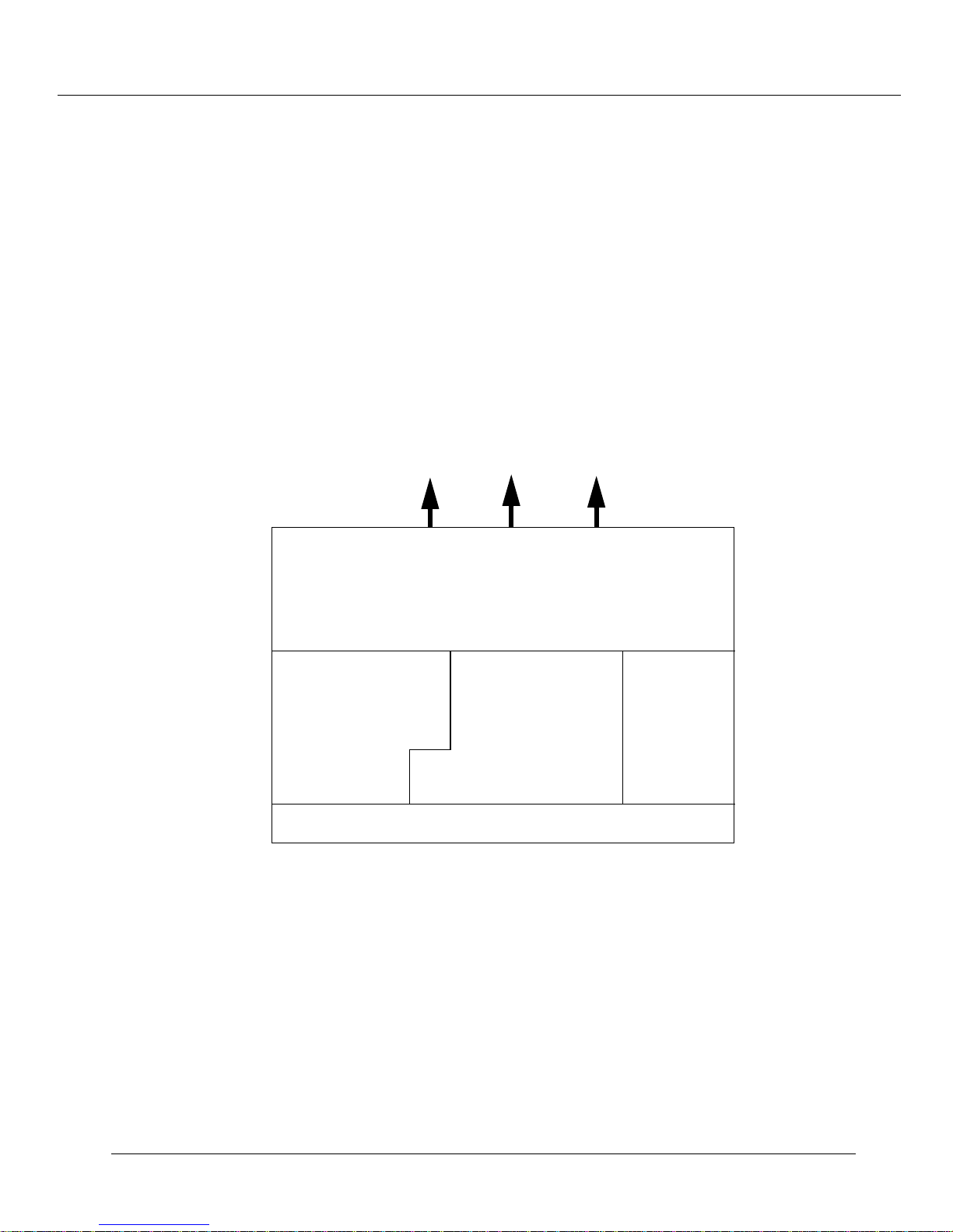
Cajun A500 Software
The Cajun A500 system software architecture, as shown in Figure , is comprised of the
following functional components:
Figure 1-1: Cajun A500 Software Architecture
Cajun A500 ATM Switch Overview
SWP
MAKER
BUS
SAR
L
F
H
ETHER
P
P
P
LANE
LEC
IP
S
I
G
N
A
L
TCP
UDP
Te ln et
TFTP
CAC
P
N
N
I
U UNI Management Task (UNI mgmt task) manages the call control signaling
messages. These messages pertain to the calls terminated locally in the switch
control processor.
U Signaling Task sets up, maintains, and tears down connections used for control
information within an Cajun A500 system. These connections are used both for
Shortest Path First (SPF) messages and for connections enabling remote access to a
Cajun A500 via ATM.
U Routing Task computes and maintains neighboring system (neighbor)
connectivity and distributes the link state database.
U Switch Monitor Task manages overall Cajun A500 operation, including event
handling and statistic gathering, as well as the Operations And Maintenance
(OAM) of the PHY modules.
U Ethernet Driver initializes and monitors the Ethernet controller.
U SAR Driver reassembles incoming traffic to the switch processor and segments
outgoing traffic from the switch processor.
Cajun A500 ATM Switch User Guide 1
-3
Page 18

Cajun A500 ATM Switch Overview
Chassis Monitor Task monitors the physical components on the Cajun A500,
U
including fan operation and system temperature.
LANE Client Task exchanges traffic (primarily telnet) to the Cajun A500 system.
U
This task receives and transmits in-band 1483 traffic from remote management
entities, including a LAN Emulation Configuration Server (LECS) and LAN
Emulation Server (LES).
U Console Task controls the command line interface for the Cajun A500.
U Switch Driver controls and monitors the ATMS200 and ATM Switch chip set. This
chip set is primarily responsible for creating and maintaining connections.
U SNMP Agent implements the SNMP that enables the remote management of the
devices.
1-4 Cajun A500 ATM Switch User Guide
Page 19
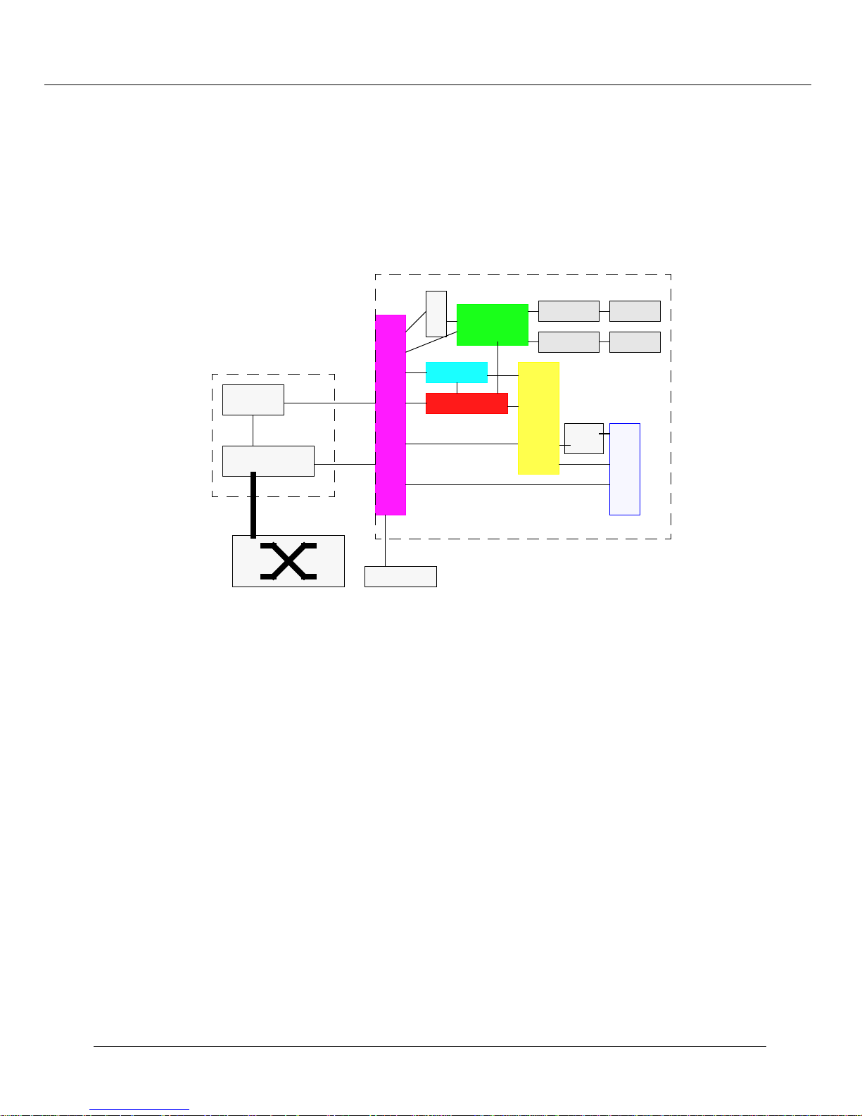
Data Flow
The data and control flow in this architectures are shown in Figure 1-2.
SWP
Cajun A500 ATM Switch Overview
Figure 1-2: Software Architecture - Major Data and Control Paths
Console
Task
P N NI R o u tin g
Task
DUART Driver
ILMI
Task
UN I/PN N I Signaling
Ch assimo n
TAS K
Snooping
Task
LEGEND
Data
Control
Task
Call Control
Tas k
Switch
M on/Ctrl
Switch Driver
Teln et
Se rv ic e M gt.
TFTP
Local
SAR
ATM
Switch
SNM P
Agent
MAKER
BUS
Trap
N o tify
PNA(IP)
Ether Driver
C lie nt
LANE
/
PPP
To
Modem
To
Ethernet
The following steps explain how ATM cell traffic is passed through an Cajun A500
switch:
1. ATM cells from the ATM ports are stored in the cell memory under the switch
fabric control.
2. ATM cells are either forwarded to another ATM port at the line speed or to the
SAR, if circuit terminates locally (Signaling/Routing Engine, etc.).
3. The Segmentation And reassembly (SAR) reassembles the cells to a Protocol Data
Unit (PDU) and notifies the appropriate local task.
Cajun A500 ATM Switch User Guide 1-5
Page 20

Cajun A500 ATM Switch Overview
4. The local task processes the PDU and performs the appropriate action. For example,
the Signaling/Routing Engine parses the PDU and determines the forwarding path.
A cross-connection through the switch is setup, if necessary.
5. The forwarded PDUs are passed to the Segmentation and Reassembly (SAR) unit.
6. The SAR segments the PDU and hands off the cells to the switch for transmission.
7. Ethernet traffic is management traffic that is handled locally.
PNNI Routing Task
The PNNI Routing function includes computing and maintaining neighbor connectivity
and distributing the link state database amongst the physical and logical peer groups. The
Routine Service portion specifically, is consulted by the signalling task for forwarding
signalling messages to the appropriate destination.
ILMI Task
The Integrated Local Management Interface (ILMI) includes auto-negotiation, address
and service registration, and exchange of link information with the peer ILMI
component across all the physical links.
Call Control Task
The call control processing includes configuring the signalling task, interfacing with the
Switch Fabric control components, interfacing with the local CAC, and associating the
incoming and outgoing call processing.
UNI/PNNI Signalling Task
UNI/PNNI Signaling is responsible for setting up, tearing down, and maintaining UNI
3.0/3.1/4.0 as well as PNNI connections.
1-6 Cajun A500 ATM Switch User Guide
Page 21

Internal Static IP Connectivity
The Cajun A500 supports internal static IP connectivity. This functionality enables you to
manage the switches when there is no ethernet or LANE services available. You
configure one switch as the designated A500 or static IP server and all other switches in
the topology are configured as static IP client. The static IP server keeps a table that maps
the ATM addresses of the static IP clients to their respective IP addresses.
The static IP server also creates Inband connections to each of the static IP clients. In this
way, ethernet connectivity is required only to the designated A500/static IP server. The
static IP server acts as a proxy for the static IP clients and bridges across the ethernet to
the Inband ATM connections to the static IP clients. The result is that you only need an
out-of-band connection to the static IP server and from this connection can access (via
telnet, web, SNMP etc.) all of the other switches via the Inband connections.
Note: Hijacking the Ethernet Port: static IP is used to create IP connection (e.g.,
Telnet, SNMP) to A500 switches when LANE is not available. When LANE is
available, LANE is the preferred method to provide IP connection.
Cajun A500 ATM Switch Overview
On the static IP server, the Network Management System (NMS) is on the ether
port; there is no instance of an ethernet interface and user defines the static IP
address for the box (Managed Entity).
On the static IP Client, there can exist an instance of the ethernet interface,
where the ethernet must be on a subnet other than the NMS subnet. When
static IP is in use, the NMS should be on the same network as the ME, e.g.,
A500. If this is not the case, the default gateway must be on the same network
as the Static IP address. This applies to both the client and server A500s. This
forces the IP traffic to flow on the static IP Interface.
Note: Ethernet Filtering in Promiscuous Mode: To provide static IP, the ethernet
interface (physical port) must be placed in promiscuous mode. This mode
enables the static IP server to receive unicast MAC frames destined for
Static-IP Clients. To avoid overwhelming the A500 with ethernet traffic, a
filter has been defined to only accept those frames with an OUI matching that
of the static IP server. If the OUI ever changes on a A500 you add later, that
A500 will not transmit data.
This functionality supports in-band communication from an ethernet attached
management station on one Cajun A500 to the other Cajun A500s in the network. This
capability is only available when LANE in not available in the network. Figure 1-3
depicts the typical situation where this functionality is available.
Cajun A500 ATM Switch User Guide 1
-7
Page 22
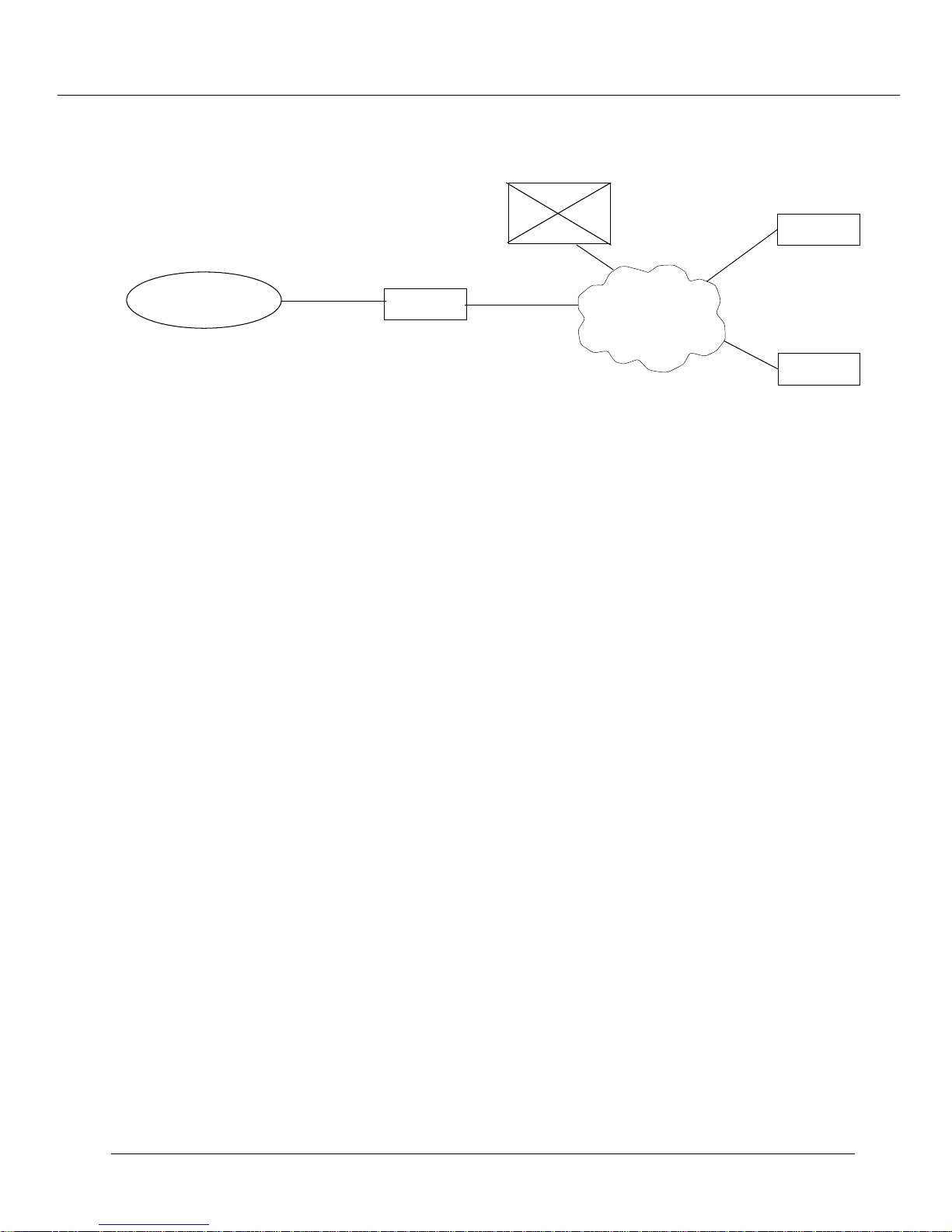
Cajun A500 ATM Switch Overview
Figure 1-3: Static IP Functionality
LANE
Server
Management
Station
Ethernet
A500
ATM
Cloud
When LANE-enabled, all of the Cajun A500s and the management station join the same
ELAN in order to achieve management connectivity. When local-access enabled, the
Cajun A500s do not automatically attempt to join the management ELAN. You must
configure the Cajun A500 where the management station resides, (the designated A500)
with the ATM addresses, ethernet addresses and IP addresses of the other Cajun A500s.
The other A500s establish a VCC to the designated A500. A simplified form of bridging
takes place in the designated Cajun A500 with respect to the treatment of frames
received over the local ethernet segment and the VCCs to the other Cajun A500s to
provide the required frame forwarding.
A500
A500
Static IP Architecture
When LANE-enabled, there are two separate PNA interfaces, and thus IP addresses, that
correspond to the local ethernet and the Cajun A500s LEC. When the designated A500 is
in local-access mode, the VCC to the designated A500 takes the place of the LEC
interface. The major difference is that this VCC to the designated A500 is treated like the
local ethernet, meaning:
U All frames sent by the Cajun A500 out of the PNA local-access interface are sent to
the VCC to the designated A500.
U All frames received over the VCC from the designated A500 are sent to the
corresponding PNA interface.
When in Local-access mode and not the designated A500, a Cajun A500 is configured
with the ATM address of the designated A500. The Cajun A500 continuously attempts to
setup a connection with the designated A500. An ATM address selector value is reserved
for this use.
-8 Cajun A500 ATM Switch User Guide
1
Page 23
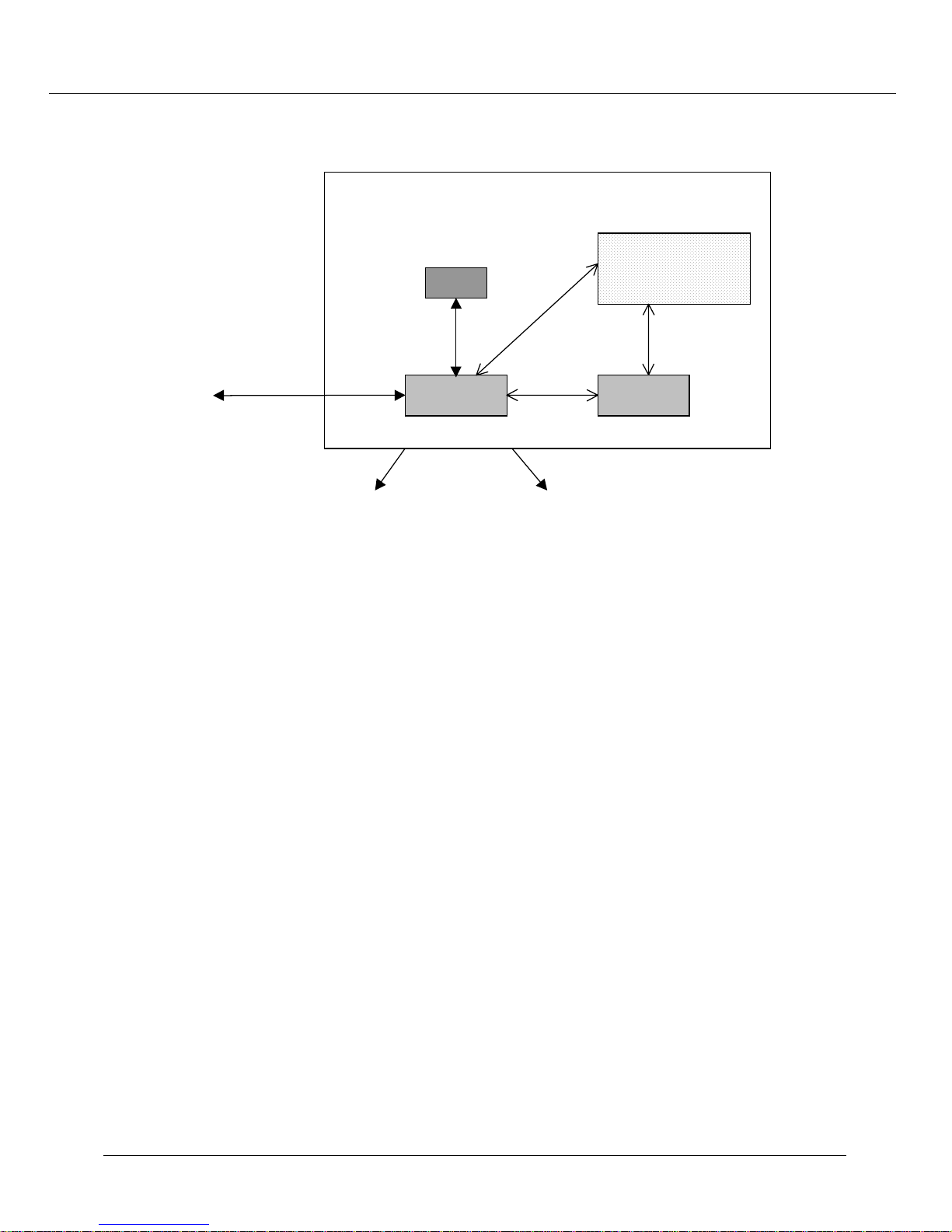
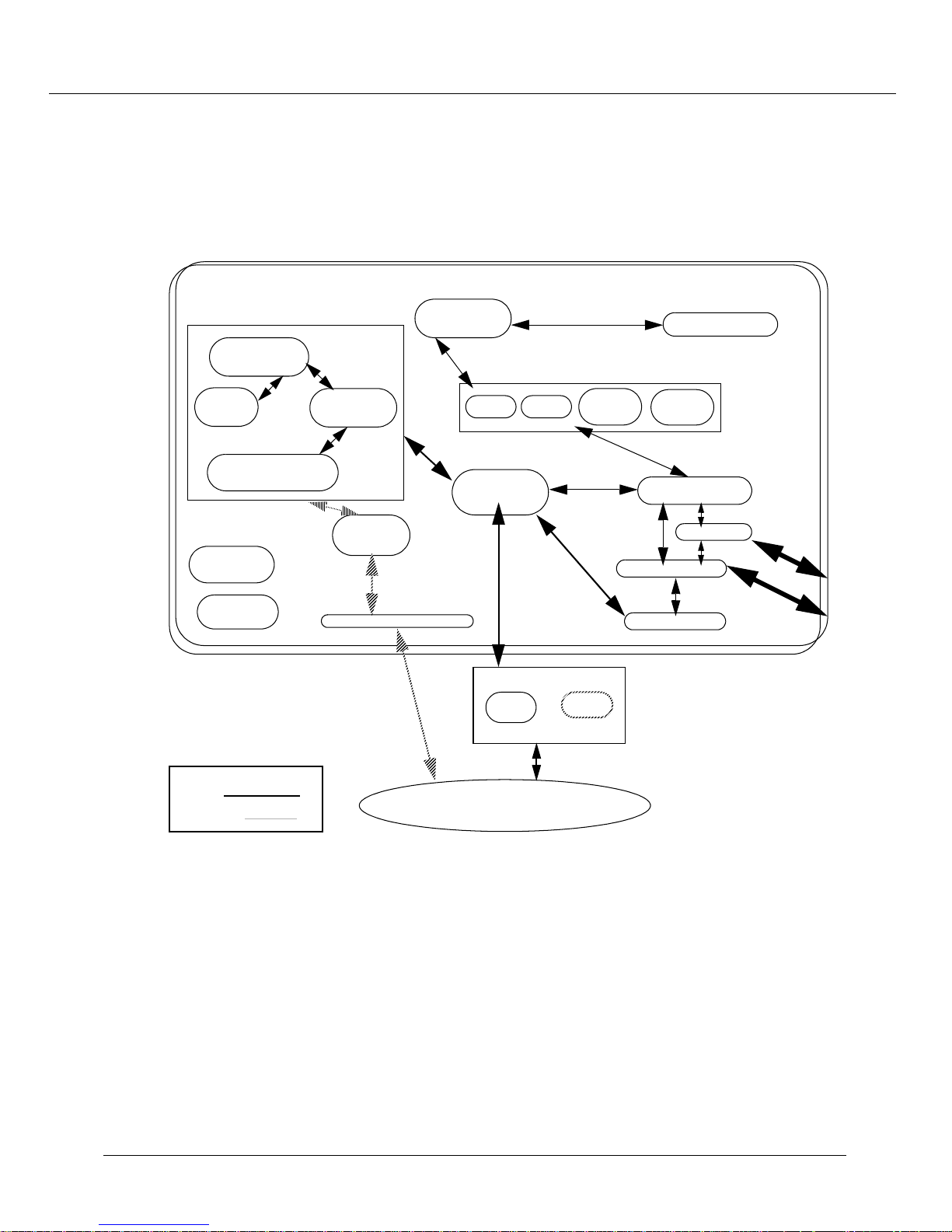
Figure 1-4: Local-access Mode
'HVLJQDWHG$
PNA
Cajun A500 ATM Switch Overview
MAC – IP – Port
Mapping Table
(MIPM)
Mini-Bridge
Local Ethernet
Proxy-ARP
Handler
«
VCCs to other A500s
The designated A500 is configured with the ATM, MAC and IP addresses of the other
Cajun A500s in the network.
Note: The MAC address is the one associated with the LEC, not the ethernet port.
U The designated A500 accepts a connection from another Cajun A500 if its ATM
address matches one of the configured addresses.
U The MAC and IP addresses combine to populate entries in the MIPM table. The
entry in the MIPM for PNA is the base (LEC) MAC address and IP address of the
designated A500.
U The mini-bridge examines all unicast frames received on the local ethernet and
determine whether they specify the destination MAC address of one of the A500s.
U If the frame is for one of the Cajun A500s, the mini-bridge forwards the frame onto
the associated VCC or to PNA if it is to its own MAC address. Unicast frames not
destined to the MAC address of an A500 are dropped.
U When a frame is received by the designated A500 from PNA, or from any of the
VCCs to the other A500s, it is blindly forwarded onto the local ethernet port,
regardless of whether the frame is a uni-cast, multi-cast or broadcast.
Cajun A500 ATM Switch User Guide 1
-9
Page 24
Cajun A500 ATM Switch Overview
g
g
g
When the mini-bridge receives a multi-cast frame from the local ethernet port, it is
dropped. When the mini-bridge receives a broadcast frame from the local ethernet port,
it examines the frame to determine whether it is an IP ARP. If it is an IP ARP, the
Proxy-ARP Hander (PAH) function is invoked. The PAH looks in the MIPM to see if the
specified IP address is one of the A500s. If it is, the appropriate ARP response is returned
to the local ethernet port.
SWP Operating System API
The architecture of the OS API and its relationship with the underlying operating system
and device drivers are illustrated in Figure 1-5.
Figure 1-5: OS Adaptation Layer and Underlying Components
Generic Operating S y ste m Inte rfa c e
Operating System Adaptation Layer
Timer Mana
Buffer M ana
Hi
h L e v e l I/O In te rfa c e
Other Misc
Functions
er
er
pSO S+
Device Driver
pRO BE+
Note: The implementation of the adaptation layer attempts to map directly to the
underlying operating system calls as much as possible so as to minimize the
overhead.
The OS APIs are classified into the following categories:
U User data structures
U Process management call interface, inter-process communication call interface,
buffer management call interface, timer management call interface, I/O
management call interface, and other misc call interface
1-10 Cajun A500 ATM Switch User Guide
Page 25
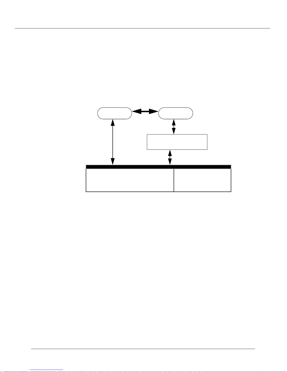
Process Communication
g
The processes running on the Switch Processor Engine (SWP) communicate via the Inter
Process Communication mechanism (IPC), provided by pSOS, the real-time operating
system used on the Cajun A500 SWP. The processes transmit and receive data to and
from the lower level drivers by registering with the Local Frame Handler layer.
Figure 1-6 describes the data flow between the software components.
Figure 1-6: Data Flow Between Software Components
Process A Process B
IPC
Network Protocols
(e.
., TCP/IP, UDP/IP)
Cajun A500 ATM Switch Overview
SOCKET
lfTxFrame/lfhISR
SAR
Driver
pSOSystem Operating System
The pSOSystem operating system is a modular, high-performance, real-time operating
system designed specifically for embedded microprocessors. It provides a complete
multi-tasking environment based on Open System standards. The pSOSystem operating
system is designed for quick start-up on both custom and commercial hardware and is
supported by an integrated set of cross development tools that can reside on UNIX or
DOS-based computers. These tools can communicate with a target device over a serial or
TCP/IP network connection.
Ether
Driver
pSOSystem Architecture
The pSOSystem operating system employs a modular architecture built around the
pSOS+ real-time multi-tasking kernel and a collection of companion software
components. Software components are standard building blocks delivered as absolute,
position-independent code modules. They are standard parts in the sense that they
remain unchanged from one application to another.
Cajun A500 ATM Switch User Guide 1
-11
Page 26

Cajun A500 ATM Switch Overview
Unlike most system software, a software component is not wired down to a piece of
hardware. It makes no assumptions about the execution/target environment. At startup,
each software component is configured by reading a user-defined table containing both
hardware and application parameters. Every component implements a logical collection
of system calls. To the application developer, system calls appear as re-entrant C
functions that can be called from an application. Any combination of components can be
incorporated into a system to match your real-time design requirements. The
pSOSystem operating system includes the following components:
U pSOS+ Real-time Multi-Tasking Kernel - A field-proven, multi-tasking kernel
that provides an efficient mechanism for coordinating the activities of your
real-time system.
U pSOS+m Multiprocessor Multi-Tasking Kernel - Extends the pSOS+ feature
set to operate across multiple, tightly-coupled or distributed processors.
U pNA+ TCP/IP Network Manager - A complete TCP/IP implementation,
including gateway routing, UDP, ARP, and ICMP protocols. It uses a standard socket
interface that includes stream, datagram, and raw sockets.
U pRPC+ Remote Procedure Call (RPC) Library - Offers SUN
and XDR services and enables you to build distributed applications using the
familiar C procedure paradigm.
U pREPC+ ANSI C Standard Library - Provides familiar ANSI C run-time
functions such as printf(), scanf(), etc. in the target environment.
Clock Synchronization
The Cajun A500 has the ability to synchronize the clock reference being used for all of its
OC-3c, OC-12c, and T3/E3 ports to an external reference. The external reference can be
any of its OC-3c, OC-12c, and T3/E3 ports in its chassis, from an T1/E1 circuit (used
specifically for clocking purposes) connected to the SWP board, or from the T3/E3 board.
You select and prioritize four external references (two OC-3c/OC-12c, or T3/E3 ports
and two T1/E1 ports) for use as the clock reference for the Cajun A500. The external
source with the highest priority is used as the external source that the Cajun A500 locks
to. If the selected source goes bad, an external source with the next highest priority is
used. If all the external references go bad, the Cajun A500 generates timing using a
holdover mode. In holdover mode, the Cajun A500 regenerates the timing of the last
source it was locked to and uses this timing as its reference source. If there was not a
good last source, the Cajun A500 enters free mode, generating timing from an on-board
oscillator.
-compatible RPC
1-12 Cajun A500 ATM Switch User Guide
Page 27

Connection Admission Control (CAC)
The Cajun A500 software supports connections using UBR, CBR, and Variable Bit Rate
non-real time (VBR-nrt) QoS classes concurrently. This integrates both voice and data
switching traffic over a common Cajun A500 ATM platform. UBR is used to support the
majority of data switching applications, such as LANE, Classical IP over ATM, and Virtual
LANs (VLANs) over ATM. CBR and VBR-nrt will be used to support voice traffic
connections.
In order to guarantee delivery of CBR and VBR-nrt cells through the switch fabric and to
the outgoing port, the Cajun A500 uses CAC. The use of CAC ensures that an output
port is not oversubscribed. For example, if port A1.1 currently has 95% of its outgoing
bandwidth reserved for existing CBR connections and a connection request is made for
10% of the port's bandwidth, the CAC rejects the request. However, if the request is
made for 5% or less, the request is accepted.
Note: The CAC does not effect UBR traffic. UBR traffic is best effort and is never
guaranteed to be delivered.
Cajun A500 ATM Switch Overview
PNNI Functionality
The Cajun A500 PNNI supports the following:
U Single peer groups
U Separate virtual network routing domains
The Cajun A500 ATM Switch provides Private Network-to-Network Interface (PNNI), a
dynamic routing protocol that manages and allocates network resources for SVCs in an
ATM network. It keeps track of the current status of all switches and links in order to
manage resources and dynamically creates routing tables in ATM switches. When an end
station requests a connection with specific QoS parameters, PNNI is able to find a
possible path (if any) satisfying the request and allocates the necessary resources in the
network.
PNNI enables the network to respond quickly to link failures, link recoveries, and
changing network loads on any link. The network is able to adapt to changes in the
addressing of a network or the topology of the network as switches are added or deleted.
Peer Groups
PNNI creates groups for the distribution of routing information through the network.
These groups are called peer groups. A peer group should have topological significance in
which all members of the group are in the same physical location.
Cajun A500 ATM Switch User Guide 1
-13
Page 28

Cajun A500 ATM Switch Overview
Point to Point Protocol (PPP)
The Cajun A500 ATM Switch provides Point to Point Protocol (PPP) functionality. PPP
provides a standard method for transporting packets of any protocol over a
point-to-point link. It encapsulates network packets into a format suitable for a serial
link. PPP can carry many different types of networking protocols, including TCP/IP,
UDP/IP, AppleTalk
call into the A500 and access Telnet, TFTP, and the SNMP functionality. In addition, the
Cajun A500 can dial out when triggered by a Trap/Notify event.
PPP has three main components:
U A method for encapsulating datagrams over serial links.
U A Link Control Protocol (LCP) for establishing, configuring, and testing the
data-link connection.
U A family of Network Control Protocols (NCPs) for establishing and configuring
different network-layer protocols.
TM
, IPX, and DECnetTM. The Cajun A500 functionality enables you to
In order to establish communications over a point-to-point link, each end of the PPP link
must first send LCP packets to configure the data link during Link Establishment phase.
After the link has been established, PPP provides for an optional Authentication phase
before proceeding to the Network-Layer Protocol phase.
Figure 1-7 displays the software architecture for the Cajun A500 with PPP. This
architecture enables applications (Telnet, TFTP, SNMP, Trap) to run over PPP as if it was
any other network interface (i.e. ethernet).
-14 Cajun A500 ATM Switch User Guide
1
Page 29

Cajun A500 ATM Switch Overview
Figure 1-7: Software Architecture with Point to Point Protocol
R o u ting
Tas k
Chassimon
Tas k
Snooping
Task
LEGEND
Data
Control
Signaling
Tas k
............
UNI
Tas k
M on/Ctrl
Mgmt
S w itc h
Console
Tas k
Loca l Direct Mod em C on sole
Teln e t
L o ca l S e rv ic e M gt./ LF H
SAR
Switch Driver
ATM
Switch
TFTP
LANE Client
SNM P
Agent
Ether Driver
Trap
Notify
PNA (IP)
DUART Driver
Modem
To Ethernet
/
PPP
local
Point-to-Point Protocol (PPP) Functionality
The Cajun A500 ATM Switch comes up by default with PPP already configured for a
dialin connection. This allows for ease in setting up a PPP session with the A500. Default
values are:
U Local IP address - 192.168.55.1
U Subnet Mask - 255.255.255.0
U Peer IP address - 192.168.55.2
U Password Authentication Protocol (PAP) is required- Lucent name and password
If these addresses conflict with other IP subnets in your system, you must change them.
These particular addresses were selected because they are the only addresses that work
for dialout on some versions of the PC dialup adapter.
Cajun A500 ATM Switch User Guide 1-15
Page 30

Cajun A500 ATM Switch Overview
Note: When PPP configuration changes are made, you must reboot the Cajun A500
for the changes to take effect. It does not need to be restarted when editing
PAP or Challenge-Handshake Authentication Protocol (CHAP) tables.
You cannot directly disable the dialin channel like you can the dialout channel. If you
must disable the dialin channel, you can:
Set PAP or CHAP as required.
U
Clear all entries in the PAP/CHAP table.
U
Another method to disable the dialin channel would be to add
U
dialstring (then the modem would never answer a call coming in).
Both channels always use active mode, which means that they try to initiate the
negotiations as soon as the physical modem link is up.
About IP addresses
When using WindowsTM 95, the mask is not particularly important if you are setting up a
point-to-point network).
Note: Performance markedly improves if the peers are in the same subnet.
If the addresses are not on the same subnet then the PC must be setup to use the default
gateway in order for applications to run. It is recommended that you configure both local
and peer address on the same subnet at the A500. Set the dialout name and password
required by the PC for autentication.
ATS0=0
to the dialin
Modem Connections
If the modem connection is removed and then plugged back in to the A500, it is not
always detected (this appears to be modem dependent). Recycling the power on the
modem works most of the time. You can tell if it works if the AA (Auto Answer) light
comes on if successful. Another method is to reboot the A500.
The default modem setup and dialstrings are simple so that they work as broadly as
possible. But, if you really need to change modem setup, dial or hangup strings,
Table 1-1. lists chat special character codes you may need in addition to the AT command
set for your modem.
-16 Cajun A500 ATM Switch User Guide
1
Page 31

Cajun A500 ATM Switch Overview
Table 1-1. Chat Special Character Codes
Code Code Function
\s Send or Receive a space character.
\t Send or Receive a horizontal tab.
\n Send or Receive a line feed character.
\r Send or Receive a carriage return.
\\ Send or Receive a backslash.
\^ Send or Receive a carat.
\ddd Send or Receive a character specified in octal digits.
\p Pause for .25 seconds before proceeding, (send only).
\dx Delay for x seconds (send only).
\K Send a break (.25 seconds of zero bits).
\c Don't append a carriage return after proceeding string (send only).
\T Insert the telephone number.
\P Insert the password.
\U Insert the user login.
\N Send nothing.
You may need to change the dialout script if there is a preliminary authentication
required at the modem level. In addition, you can use the two patterns ABORT and
TIMEOUT. The following is an example of a dialout script where there is a preliminary
authentication.
TIMEOUT 3 ABORT NO\sCARRIER ABORT BUSY ABORT NO\sDIALTONE \N AT OK ATDT\T
CONNECT \N login: \U password: \P
Figure 1-8 displays an expanded picture of the functionality provided by PPP.
Cajun A500 ATM Switch User Guide 1
-17
Page 32

Cajun A500 ATM Switch Overview
Figure 1-8: PPP Functionality Overview
To/From pNA (IP)
PPP actually provides NI interface
PPP
Link Control Protocol Authentication IP Control Protocol
HDLC
Serial Port
Modem
Ip Control Protocol
PPP provides modem support also
in the form of scripts.
1. You must set up the serial port and modem to receive calls in order to use the
SNMP agent or Telnet applications.
2. The modem must be dialed to use the trap application.
3. After the modem connection is made then the Link Control Protocol (LCP) runs to
perform the layer 2 configuration of the link (maximum packet size, which
characters must be sent masked etc.).
4. The initialization of PPP occurs after all of the other Cajun A500 tasks begin.
If PPP is not enabled the modem is set up to accept calls and start a console task
when a call comes in.
If PPP is enabled, a PPP task is created and starts to manage the two possible
virtual channels. The new task reads the PPP configuration data from the
NVRam. The PPP task activates on a timer event.
1-18 Cajun A500 ATM Switch User Guide
Page 33

Cajun A500 ATM Switch Overview
Initially, the PPP task configures the channel for dialin mode and starts the PPP network
interface; this creates and starts the PPP daemon. The PPP daemon waits on
initialization, send, receive, and control events. The serial port and modem are initialized
through the PPP daemon. The PPP task has the following duties when set up:
U Checks message queue for a trap message - If there is a trap message, it saves
the information in a private log. If the trap is the first one in, the log starts a hold
trap message timer.If the log is almost full (ten events) then change PPP network
configuration to dialout and send trap. After last trap is sent out the PPP channel
waits five seconds and then shuts down the dialout connection and returns to
waiting for dialin connection.
U Checks to see if hold trap message timer has expired - If yes, then configure
the channel for dial out and send the trap.After the last trap is sent out the PPP
channel, wait five seconds and then shuts down the dialout connection and goes
back to waiting for dialin connection.
U Checks the link status - If link was up and then goes down again, reset the
modem and start waiting for dialin connect again.
The PPP task does not break down a dialin connection enricher to send out a trap
in the above cases. Instead it waits for dialin link to be disconnected.
Authentication Configuration
PPP defines a Link Control Protocol, which enables negotiation of an Authentication
Protocol for authenticating its peer before allowing Network Layer protocols to transmit
over the link. Authentication configuration options are:
U Password Authentication Protocol (PAP)
U Challenge Handshake Authentication Protocol (CHAP)
The IP Control Protocol (IPCP) is negotiated last. After this step completes, the entire link
opens so that applications can begin passing data. These authentication protocols are
intended for use primarily by hosts and routers that connect to a PPP network server via
switched circuits or dialup lines, but might be applied to dedicated links as well. The
server can use the identification of the connecting host or router in the selection of
options for network layer negotiations.
Cajun A500 ATM Switch User Guide 1-19
Page 34

Cajun A500 ATM Switch Overview
Password Authentication Protocol (PAP)
The Password Authentication Protocol (PAP) provides a simple method for the peer to
establish its identity using a 2-way handshake. This is done only upon initial link
establishment. After the link establishment phase completes, an ID/Password pair is
repeatedly sent by the peer to the authenticator until authentication is acknowledged or
the connection terminates.
Passwords are sent over the circuit in the clear, and there is no protection from playback
or repeated trial and error attacks. The peer is in control of the frequency and timing of
the attempts. Any implementations which include a stronger authentication method
(such as CHAP) must offer to negotiate that method prior to PAP.
This authentication method is most appropriately used where a plain text password must
be available to simulate a login at a remote host. In such use, this method provides a
similar level of security to the usual user login at the remote host.
Challenge-Handshake Authentication Protocol (CHAP)
The Challenge-Handshake Authentication Protocol (CHAP) is used to verify the identity
of the peer using a 3-way handshake. This is done upon initial link establishment, and
can be repeated anytime after establishing the link. After the link establishment phase
completes, the authenticator sends a challenge message to the peer. The peer responds
with a value calculated using a one-way hash function. The authenticator checks the
response against its own calculation of the expected hash value. If the values match, the
authentication is acknowledged; otherwise the connection terminates.
CHAP provides protection against playback attack through the use of an incrementally
changing identifier and a variable challenge value. The use of repeated challenges is
intended to limit the time of exposure to any single attack. The authenticator is in
control of the frequency and timing of the challenges. This authentication method
depends upon a secret known only to the authenticator and that peer. The secret is not
sent over the link. Use this method when the same secret is easily accessed from both
ends of the link.
1-20 Cajun A500 ATM Switch User Guide
Page 35

Data Flow
There are three types of messages that the system can receive:
U
U
U
The Raw packets are directed to the modem script handler. The PPP data and link packets
are decoded into a PPP owned buffer and the Async buffer is returned to the Async
buffer pool. The PPP buffers are sent to the PPP daemon which sends the link packets to
the appropriate handler (LCP, IPCP).
Transmit buffers can be generated from the same 3 sources:
U Modem chat script (raw)
U PPP link information
Cajun A500 ATM Switch Overview
PPP link packets
PPP Data packets
Raw packets
U Application data from PNA
The link and data buffers are encoded and copied into Async buffers and then
transmitted. The raw buffers follow a similar path except they are not encoded as PPP
buffers.
Cajun A500 ATM Switch User Guide 1
-21
Page 36

Cajun A500 ATM Switch Overview
1-22 Cajun A500 ATM Switch User Guide
Page 37

2
Using the Cajun A500 Manager
Overview
The Cajun A500 provides an embedded web server that enables you to set all parameters
on a particular switch. Use this interface for quick and simple configuration changes.
Logging In to the Web Agent
Although the Web Agent supports any frames-capable browser, the system has been
qualified with the following browsers:
U Netscape Navigator 4.5 or later
U Microsoft Internet Explorer 4.0 or later
To log in to the Web Agent:
1. Start your browser.
2. In the Location field, enter the URL of the switch you want to manage
(for example: http://127.255.255.0).
3. Press Enter. The login window opens.
4. Enter a valid user name. The default super user name is root.
5. Enter a valid password (if one has been set by your System Administrator). There
is no default password. The Web Agent window opens, (Figure 2-1).
Cajun A500 ATM Switch User Guide 2-1
Page 38

Using the Cajun A500 Manager
Figure 2-1. Web Agent Window
Installing Cajun A500 Help Files
Certain resources used by the Web Agent are located off the switch to preserve switch
memory. Setting up a help server location for the switch enables the switch to access
online help files for the Web Agent. Figure 2-2.provides a diagram of how the
communication works.
Figure 2-2. Online Help Server
Management
Station
You must add the files to an existing web server on your network. The Cajun A500
online Help files used by the web agent are located off the switch to preserve switch
Separate web server serves
on-line help and bitmaps.
Switch serves page content
and receives responses.
2-2 Cajun A500 ATM Switch User Guide
Page 39

Using the Cajun A500 Manager
memory. Setting up a help server location for the switch allows the switch to access the
Help files.
To install your online help on a your web server, transfer the help subdirectory to that
web server and enter the URL for that web server in the Help Server Location field.
For example, if you transfer the CajunA500 help directory to your company server ( for
example, http://www.abc-company.com) you would need to:
1. Install the online help to a windows 95 or NT node in your network.
2. Transfer the entire help subdirectory into the root of your web server.
3. Ensure that you transfer the entire directory and not just the contents of the
directory.
4. Launch a browser and connect to your Cajun A500 switch.
5. Click Server Location in the
window.
6. Enter the server location (for example, http://www.abc-company.com) in the
HTTP Server Location field.
7. Enter the directory name of your help files in the HELP Directory Location field.
8. The default for the help directory is help. You should not need to change this
unless you changed the name of your help directory prior to transferring it to your
web server.
Entering the Server Location
To set the location of the documentation server on the switch:
1. Launch a web browser and connect to your Cajun A500 switch.
2. From the menu on the left-hand side of the web agent display, select Help Server.
3. Enter the host name or IP address of the HTTP server you are using in the Help
Server Location text field.
System Configuration section of the Web Agent
4. Enter the Help Directory name in the Help Directory text field.
Cajun A500 ATM Switch User Guide 2-3
Page 40

Using the Cajun A500 Manager
Getting Updated Help Files on the Internet
The help files are available on the internet. To download this archive:
1. Create a directory on the server machine where the help files will reside (for
example, c:helpinstall).
2. Use the change directory command (cd) to change to the directory you just created.
3. Launch a web browser and go to the Cajun Installer web page at:
http://pubs.lucentctc.com/
4. Click cajun_A500.zip to download the latest help files into the directory you
previously created.
For more information on this product, refer to the documentation that comes on your
Cajun A500 ATM Switch or refer to http://pubs.lucentctc.com
online documentation there.
to review the
2-4 Cajun A500 ATM Switch User Guide
Page 41

Using the Cajun A500 Manager
Using the Cajun A500 Manager Web Agent
The Cajun A500 ATM Switch provides an embedded HTTP server that enables you to set
all parameters on a particular switch. Use this interface for quick and simple
configuration changes.
Figure 2-3. Cajun A500 Manager Menu Items
Cajun A500 ATM Switch User Guide 2-5
Page 42

Using the Cajun A500 Manager
Table 2-1. Web Agent Menu Options
Top Level Available Options
System General - provides basic system information (name, time, date, and software version)
Status - provides basic system status.
Modules - provides information regarding the modules installed in the system.
Addresses - enables you to modify system addresses.
SNMP - enables you to designate the Read, Write, and Trap Community strings.
Users - provides a listing of the current users of the A500.
Reset - enables you to reset the system.
Logs Events - accesses the Events log information.
Alarms - accesses the Alarms log information.
Statistics Switch - accesses switch cell statistics information.
Ether Port- accesses Ether port statistics information.
ATM Ports - accesses ATM port statistics information.
SAR Port - accesses SAR port statistics information.
Signaling - accesses signaling statistics information.
Virtual
Circuits
ATM Ports Configuration - enables you to configure individual ATM ports and add new VPIs.
PNNI Configuration - enables you to set the configuration options for PNNI.
Signaling ESIs - enables you to configure ESIs.
Displays the Virtual Circuit configuration information and enables you to change the
NVRAM settings for each port.
VC Table- displays the Virtual Circuit Table information for all ATM ports and enables
you to delete or add Virtual Circuits and Virtual Paths.
Statistics (Sonet) - displays ATM statistics (Port, Receive Cells, Transmit Cells).
Hmap - displays all nodes in peer groups
Neighbor - displays neighbor node information.
Node - displays node information.
Route Addresses - displays route address information.
Static Routes - enables you to configure static routes.
Cause - displays a listing of Cause Codes.
Statistics - provides signaling statistics.
2-6 Cajun A500 ATM Switch User Guide
Page 43

Top Level Available Options
Using the Cajun A500 Manager
Services LEC
Clock Sync
TFTP Enables you to use TFTP.
CLI Enables you to access the Command Line Interface (CLI) for the Cajun A500.
- LAN emulation Client configuration information.
Configuration
Static IP
PPP
dial out information.
Enables you to configure clock sync options.
- displays the static IP status.
Configuration
enable/disable static IP and set the mode for client or server.
Clients
Servers
- enables you to configure PPP. Includes addresses, authentication options, and
Authentication
Password, Message), CHAP (Hostname, Secret), Local Hostname (CHAP), Dialout
User/Password.
Modem Scripts
String, Dialin String, Dialout String, Hangup String.
- enables you to add clients.
- enables you to set the static IP server ATM address.
- enables you to configure LEC options.
- displays the Static IP NVRAM Configuration window. You can
- enables you to add clients. You can set: PAP (Username,
- enables you to access the Modem Scripts and designate: Setup
Entering Basic System Information
To enter/modify basic system identification information:
1. In the System section of the Web Agent window, select General. The System
Information dialog box opens.
2. In the Name field, enter a name for the switch.
3. In the Time field, enter the time using 24-hour time format (for example, 10 p.m.
is 22 00 00).
4. In the Date field, enter the current date.
5. Click Apply to save your changes, or Cancel to restore previous settings.
Changing Addresses
To set or modify addresses (IP Address, IP Mask, Ethernet, Inband (Client), PPP, Default
Gateway, ATM Address):
1. In the System section of the Web Agent window, select Addresses. The Addresses
dialog box opens.
2. In the appropriate box, enter the new address.
3. Click Apply to save your changes, or Cancel to restore previous settings.
Cajun A500 ATM Switch User Guide 2-7
Page 44

Using the Cajun A500 Manager
To enter the IP address and IP mask of the Cajun A500, using the CLI:
1.
Enter the
2. Press Return.
AX500: admin address
Enter IP Address [198.3.104.162]: 198.3.104.163
Enter IP Mask [255.255.255.0]: 255.255.255.0
New IP Address and Mask will be used when A500 is rebooted
Note: The new IP address and mask are not used until the device reboots.
To set or modify the Default Gateway, using the CLI:
admin address
command at the
AX500:
prompt.
1. Enter the
modify default gateway
command at the
AX500:
prompt.
2. Press Return.
AX500: modify default gateway
Enter IP gateway[198.3.104.240]:198.3.104.240
Default Gateway will be used when A500 is rebooted.
Note: The new IP address and mask are not utilized until the Cajun A500 reboots.
2-8 Cajun A500 ATM Switch User Guide
Page 45

3
Configuring the Cajun A500
Network
Overview
Once your Cajun A500 is operational, complete the following tasks to configure your
Cajun A500:
1. Determine the network configuration (i.e., the endstations or switches that will be
attached to each operational link in your Cajun A500.
2. Configure the link type accordingly.
3. Configure any static routes.
4. Configure any Permanent Virtual Circuits (PVCs).
The following sections provide detailed explanations for each of these tasks.
Determining Your Network Configuration
First, determine what kind of endstation or switch will be attached to each link on your
Cajun A500, so that you can properly configure the link type for each port. The link type
specifies how each system directly connected to the Cajun A500 establishes
communication with it. The following are some basic guidelines for determining the link
type:
U Auto Configuration - if the external you are connecting to supports ILMI 4.0, no
configuration is necessary.
U Systems such as LAN (non-ATM) switches or servers typically support UNI 3.0, 3.1,
or 4.0 signaling, using the Interim Local Management Interface (ILMI) protocol. In
these configurations, you typically only need to configure the link type to be used
by the particular ATM port on the Cajun A500. Configuration of static routes or
Permenant Virtual Circuits (PVCs) is usually not necessary. The section
"Configuring/Modifying the Link Type", describes how to configure the link type
and activate the Cajun A500 port.
U If connecting a network of Cajun A500s, you should use PNNI Routing/Signaling.
Cajun A500 ATM Switch User Guide 3-1
Page 46

Configuring the Cajun A500 Network
Third-party ATM switches and Lucent ATM switches - In these configurations, you
U
need to both set the link type and configure either a static route , PVC, or PNNI. The
section "Configuring/Modifying the Link Type", later in this chapter, describes how
to configure the link type and activate the Cajun A500 port. The section
"Configuring Static Routes", describes how to configure a static route; Section
"Configuring Permanent Virtual Channels and Paths" describes how to configure a
PVC.
Configuring the Link Types for the Cajun A500
Specify a link type to be assigned to an Cajun A500 port determines the service to be
supplied by the Cajun A500 over that port. This is done by specifying a link type from
the available set of link types for each active port in your Cajun A500.
Note: When you first bring up an Cajun A500, all ports are disabled (down). Ports
must be in this state when you configure the link type for the port.
Note: If using ILMI 4.0, and the external device supports auto-configuration, the
system auto configures and all that is necessary is bring up the port.
To configure the link type for a Cajun A500 port:
1. Bring the ATM port down, if it is not already.
2. Configure the link type.
3. Bring the ATM port up.
4. View the link types specified for each port.
5. Configure custom link types.
The following sections explain how to complete each of these steps.
Guidelines for Determining the Link Type
The following guidelines help determine which link type to use. The value you select
depends upon what the system directly attached to your Cajun A500 uses to establish
communication with the Cajun A500.
U Systems such as LAN (non-ATM) switches or servers typically support UNI 3.0, 3.1,
or 4.0 signaling, using the Interim Local Management Interface (ILMI) protocol.
U Third-party ATM switches and Lucent ATM switches that support UNI 3.0 or 3.1
signaling, use PNNI.
-2 Cajun A500 ATM Switch User Guide
3
Page 47

Bringing the ATM Port Down
To bring an ATM port down:
Configuring the Cajun A500 Network
1. In the ATM Switch A500 section of the Web Agent window, select
then select Configuration. The ATM Port Configuration window opens.
2. Select down in the Admin Status column for the port you want to bring down.
3. Click Apply to save your changes, or Cancel to restore previous settings.
To bring an ATM port down using the CLI:
1. In the ATM Switch A500 section of the Web Agent window, select CLI. A shell
window opens.
2. Execute the
more information on this command, see Chapter 6, "admin Commands".
admin downInterface
command from the Cajun A500s console. For
Configuring/Modifying the Link Type
You can then proceed to configure the link type for the port. If you are unsure of which
link type to use, refer to the section "Guidelines for Determining the Link Type". All
ports are configured in Auto Mode running on VPI 0 and are in the admin up state. This
means that as long as the box connected to the A500 supports ILMI, the ports are all
"plug and play".
ATM Ports,
PNNI does not come up and run unless the box has been configured with a valid IP
address. Therefore, all boxes in a network of A500s must have their IP addresses
administered and then they must be rebooted.
To configure/modify the link types for ATM port:
1. In the ATM Switch A500 section of the Web Agent window, select ATM Ports,
then select Configuration. The ATM Port Configuration window opens.
2. Click on the port you want to modify. The Protocol Configuration Table window for
that port opens.
3. Click Modify . The Modify/Add Protocol Configuration Table window for that
port opens.
4. Enter the information for the VPI, Admin Status, config, Ilmi, cell rate, and
max vci.
5. Click Apply to save your changes, or Cancel to restore previous settings.
Cajun A500 ATM Switch User Guide 3
-3
Page 48

Configuring the Cajun A500 Network
To configure the link type using the CLI:
1. In the ATM Switch A500 section of the Web Agent window, select CLI. A shell
window opens.
2. Execute the
information on this command, see Chapter 6, "admin Commands".
admin link_type
Bringing the ATM Port Up
After you select the link type, you must bring the port back into service on the switch. To
bring the ATM port up:
1. In the ATM Switch A500 section of the Web Agent window, select ATM Ports,
then select Configuration. The ATM Port Configuration window opens.
2. Select up in the Admin Status column for the port you want to bring up.
3. Click Apply to save your changes, or Cancel to restore previous settings.
To bring the ATM port up using the CLI:
1. In the ATM Switch A500 section of the Web Agent window, select CLI. A shell
window opens.
2. Execute the
more information on this command, see Chapter 6, "admin Commands".
admin upInterface
command from the Cajun A500s console. For more
command from the Cajun A500 console. For
Static Route Configuration
Note: It is recommended that you use PNNI. use static routes only if they are
necessary.
Most configurations enable the Cajun A500 to use ILMI to establish routes through the
network. Certain configurations, however, may require configuration of static routes or
Permanent Virtual Circuits (PVCs). The following are some guidelines to help you
determine when manual route configuration is necessary:
U Systems using the ILMI protocol to establish communication with the Cajun A500
typically do not require any manual route configuration.
U Systems that do use signaling, but do not use the ILMI protocol to establish
communication with the Cajun A500 typically use static routes.
U Systems that do not support signaling, require permanent virtual circuits.
3-4 Cajun A500 ATM Switch User Guide
Page 49

Configuring Static Routes
To add and configure static routes:
1. In the ATM Switch A500 section of the Web Agent window, select Signaling.
1. In the Signaling section of the Web Agent window, select Static Routes. The
Local Static Routes window opens.
2. Click Add New Static Route. The Add a local Static Route window opens.
3. Enter the information for the Port, VPI, Address, and Mask for the static route.
4. Click Apply to save your changes, or Cancel to restore previous settings.
To configure this kind of static route using the CLI:
1. In the ATM Switch A500 section of the Web Agent window, select CLI. A shell
window opens.
Configuring the Cajun A500 Network
2. Execute the
console. For more information on this command, see Chapter 6, "admin
Commands".
admin signaling route add
Deleting a Static Route
To delete static routes:
1. In the ATM Switch A500 section of the Web Agent window, select Signaling.
1. In the Signaling section of the Web Agent window, select Static Routes. The
Local Static Routes window opens.
2. Select the static route you want to delete and click Delete . The information
appears for the static route you deleted.
To delete a static route, using the CLI:
1. In the ATM Switch A500 section of the Web Agent window, select CLI. A shell
window opens.
2. Execute the
console. For more information on this command, see Chapter 6, "admin
Commands".
admin signaling route remove
command from the Cajun A500
command from the Cajun A500
Cajun A500 ATM Switch User Guide 3-5
Page 50

Configuring the Cajun A500 Network
Adding End Station Identifiers
To add new end station identifiers:
1. In the
1. In the Signaling section of the Web Agent window, select ESIs. The End Station
Identifier window opens.
2. Click Add New ESI. The Add an End Station Identifier (ESI) window opens.
3. Enter the appropriate Port, VPI, and ESI information.
4. Click Apply to save your changes, or Cancel to restore previous settings.
To add an ESI, using the CLI:
1. In the ATM Switch A500 section of the Web Agent window, select CLI. A shell
window opens.
2. Execute the
For more information on this command, see Chapter 6, "admin Commands".
ATM Switch A500 section of the Web Agent window, select Signaling.
admin signaling esi add
Deleting End Station Identifiers
To delete and ESI:
1. In the ATM Switch A500 section of the Web Agent window, select Signaling.
command from the Cajun A500 console.
1. In the Signaling section of the Web Agent window, select ESIs. The End Station
Identifier window opens.
2. Select the ESI you want to delete and click Delete . The End Station Identifier
window opens displaying the "ESI successfully removed" message.
To delete an ESI, using the CLI:
1. In the ATM Switch A500 section of the Web Agent window, select CLI. A shell
window opens.
2. Execute the
console. For more information on this command, see Chapter 6, "admin
Commands".
admin signaling esi remove
command from the Cajun A500
-6 Cajun A500 ATM Switch User Guide
3
Page 51

Configuring the Cajun A500 Network
Configuring Permanent Virtual Channels and Paths
Permanent Virtual Circuits (PVCs) are circuits that are manually configured and remain
in place until they are manually removed by the network administrator. PVCs are
typically used when the directly attached system does not support signaling. There are
two basic kinds of PVCs:
U Point-to-point - These bi-directional PVCs are configured when there are only
two endstations communicating.
U Point-to-multipoint - These uni-directional PVCs are configured when there is
one source endstation and multiple receiving endstations.
Adding Virtual Channels or Paths
To add a virtual channel:
1. In the ATM Switch 500 section of the Web Agent window, select Virtual
Circuits.
2. Select VC Table. The Virtual Circuits Table For All ATM Ports window opens. Scroll
to the bottom of the window.
3. Click on Add Virtual Channel. The Add Virtual Channel window opens.
4. Click on Add Virtual Path. The Add Virtual Path window opens.
5. Fill in the appropriate information.
6. Click Apply to save your changes, or Cancel to restore previous settings.
To add a virtual channel using the CLI:
1. In the ATM Switch A500 section of the Web Agent window, select CLI. A shell
window opens.
2. Execute the
on this command, see Chapter 8, "modify Commands".
To configure a point-to-multipoint PVC using the CLI:
1. In the ATM Switch A500 section of the Web Agent window, select CLI. A shell
window opens.
2. Execute the
on this commands, see Chapter 8, "modify Commands".
modify add_channel point-point command.
modify add_channel multipoint
command. For more information
For more information
Note: The initial connection is added to the switch table, while the second
connection was bifurcated in the switch table.
Cajun A500 ATM Switch User Guide 3-7
Page 52

Configuring the Cajun A500 Network
Deleting Virtual Channels or Paths
Note: Virtual Circuits and Virtual Paths that are reserved for signaling cannot be
deleted.
To delete a virtual channel or path:
1. In the ATM Switch 500 section of the Web Agent window, select Virtual
Circuits.
2. Select VC Table. The Virtual Circuits Table For All ATM Ports window opens.
3. Click Delete . The information appears for the channel you deleted.
CAUTION: If you accidentally delete the wrong Virtual Circuit/Virtual Path,
follow the steps in the "Adding Virtual Channels or Paths" section to
replace the VC/VP.
To delete a PVC using the CLI:
1. In the ATM Switch A500 section of the Web Agent window, select CLI. A shell
window opens.
2. Execute the
modify rem_channel
command from the console. For more
information on this commands, see Chapter 8, "modify Commands".
Note: You use the same command when removing a point-to-point connection or a
leaf from a point-to-multipoint connection.
Note: When tearing down a point-to-multipoint connection, each leaf must be
removed individually. There is no single command to tear down both the root
and leaves of a point-to-multipoint connection.
3-8 Cajun A500 ATM Switch User Guide
Page 53

Configuring the Cajun A500 Network
Configuring LAN Emulation Client (LEC) Services
The Web Agent enables you to configure LAN Emulation Client (LEC) services. To
configure these services:
1. In the ATM Switch A500 section of the Web Agent window, select Services, then
select LEC. The LEC Configuration window opens.
2. Select the Mode (Enabled/Disabled).
3. Enter the Initialization Method to use.
4. Enter the Server ATM Address.
5. Enter the ELAN Name to use.
6. Click Apply to save your changes, or Cancel to restore previous settings.
To configure the LEC options, using the CLI:
1. In the ATM Switch A500 section of the Web Agent window, select CLI. A shell
window opens.
2. Execute the
Chapter 6, "admin Commands".
admin lec
Static IP Connectivity
The Cajun A500 supports Internal Static IP connectivity. This functionality enables you
to manage the switches when there is no ethernet or any LANE services available. This
functionality supports in-band communication from an ethernet attached management
station on one Cajun A500 to the other Cajun A500s in the network. This capability is
only available when LANE in not available in the network. See Figure 1-3 for more
information.
U You configure one switch as the designated A500 or static IP server.
U You configure all other switches in the topology as static IP clients.
Static IP Server
The server keeps a table that maps the ATM addresses of the clients to their respective IP
addresses.The server also creates Inband connections to each of the clients. In this way,
ethernet connectivity is required only to the designated A500 static IP server. The server
acts as a proxy for the clients and bridges across the ethernet to the inband ATM
connections to the clients. The result is that you only need an out-of-band connection to
the server and from this connection can access (via telnet, web, SNMP etc.) all of the
other switches via the static IP connections.
commands. For more information on these commands, see
Cajun A500 ATM Switch User Guide 3-
9
Page 54

Configuring the Cajun A500 Network
Hijacking the Ethernet Port
Static IP is used to create IP connection (e.g., Telnet, SNMP) to A500 switches when
LANE is not available. When LANE is available, LANE is the preferred method to provide
IP connection. On the static IP server, the Network Management System (NMS) is on the
Ether port; there is no instance of an ethernet interface and user defines the static IP
address for the box (Managed Entity). On the Static IP Client, an instance of the ethernet
interface can exist, where the ethernet must be on a subnet other than the NMS subnet.
When static IP is in use, the NMS should be on the same network as the ME, e.g., A500.
If this is not the case, the default gateway must be on the same network as the static IP
address. This applies to both the client and server A500s. This forces the IP traffic to flow
on the static IP interface.
Ethernet Filtering in Promiscuous Mode
To provide static IP, you must place the ethernet interface (physical port) in promiscuous
mode. This mode enables the static IP server to receive unicast MAC frames destined for
static IP clients. To avoid overwhelming the A500 with ethernet traffic, a filter has been
defined to only accept those frames with an OUI matching that of the static IP server.
Configuring Static IP
The Web Agent enables you to configure your static IP configuration, clients, and server.
To configure static IP:
1. In the ATM Switch A500 section of the Web Agent window, select Services, then
select Static IP. The Static IP Status window opens with the Status and Mode
information.
2. Select Configuration. At the Static IP Nvram Configuration screen you can
select Enable or Disable for the Status and Client or Server for the mode.
3. Click Apply to save your changes, or Cancel to restore previous settings.
To configure these connections, using the CLI:
1. In the ATM Switch A500 section of the Web Agent window, select CLI. A shell
window opens.
2. Execute the
enable_server
Chapter 6, "admin Commands".
admin static_ip enable_client
commands. For more information on these commands, see
and
admin static_ip
-10 Cajun A500 ATM Switch User Guide
3
Page 55

Adding Static IP Clients and Servers
The Web Agent enables you to configure your static IP clients and server. To configure
static IP clients and servers:
1. In the ATM Switch A500 section of the Web Agent window, select Services, then
select Static IP. The Static IP Status window opens with the Status and Mode
information.
2. Select Clients. At the Static IP Clients window, you can add a client by entering
the IP, MAC, and ATM addresses.
3. Click Apply to save your changes, or Cancel to restore previous settings.
4. Select Server. At the Static IP Server window, enter the ATM address for the
server.
5. Click Apply to save your changes, or Cancel to restore previous settings.
To configure static IP clients and servers, using the CLI:
Configuring the Cajun A500 Network
1. In the ATM Switch A500 section of the Web Agent window, select CLI. A shell
window opens.
2. Execute the
set_server
"admin Commands".
admin static_ip add_client
commands. For more information on these commands, see Chapter 6,
and the
admin static_ip
Configuring Private Network-to-Network Interface (PNNI)
To configure PNNI:
1. In the ATM Switch 500 section of the Web Agent window, select PNNI.
2. Select Configuration. The PNNI Configuration window opens.
3. Enter the PNNI Level.
4. Click Apply to save your changes, or Cancel to restore previous settings.
To configure PNNI, from the CLI:
1. In the ATM Switch A500 section of the Web Agent window, select CLI. A shell
window opens.
2. Execute the
see Chapter 6, "admin Commands".
Cajun A500 ATM Switch User Guide 3-11
admin pnnilevel
command. For more information on this command,
Page 56

Configuring the Cajun A500 Network
Configuring Point-to-Point Protocol (PPP)
To configure PPP:
1. In the Services section of the Web Agent window, select PPP.
2. Enter the PPP Addresses information.
3. Enter the Authentication Required information.
4. Enter the Dialout Options information.
5. Click Apply to save your changes, or Cancel to restore previous settings.
To configure PPP, using the CLI:
1. In the ATM Switch A500 section of the Web Agent window, select CLI. A shell
window opens.
commands from the Cajun A500 console. For more information
2. Execute the
on these commands, see Chapter 9, "PPP Commands".
PPP
Configuring PPP Authentication
To configure PPP authentication:
1. In the Services section of the Web Agent window, select PPP.
2. Select the Authentication. The Authentication Tables window opens.
3. Enter the PAP Table information (Username, Password, and Message).
4. Enter the CHAP Table information (Hostname and Secret).
5. Enter the Local Hostname (CHAP) information.
6. Enter the Dialout User/Password information (Username and Password).
7. Click Apply to save your changes, or Cancel to restore previous settings.
To configure PPP authentication, using the CLI:
1. In the ATM Switch A500 section of the Web Agent window, select CLI. A shell
window opens.
commands from the Cajun A500 console. For more information
2. Execute the
on these commands, see Chapter 9, "PPP Commands".
PPP
3-12 Cajun A500 ATM Switch User Guide
Page 57

Configuring PPP Modem Scripts
To configure PPP modem scripts:
1. In the Services section of the Web Agent window, select PPP.
2. Select Modem Scripts. The Modem Scripts window opens.
3. Enter the Setup String, Dialin String, Dialout String, and Hangup String
information.
4. Click Apply to save your changes, or Cancel to restore previous settings.
To configure PPP authentication, using the CLI:
1. In the ATM Switch A500 section of the Web Agent window, select CLI. A shell
window opens.
2. Execute the PPP Commands from the Cajun A500 console. For more information
on these commands, see Chapter 9, "PPP Commands".
Configuring the Cajun A500 Network
Configuring Operations Administration and Maintenance
(OAM)
To configure OAM:
1. In the Services section of the Web Agent window, select OAM. The OAM F4/F5
Fault Management Cells window opens.
2. Select Segment and End2End in the Insert Loopback Cell section.
3. Select Create in the Segment End section.
4. Select the Connection Type and Port.
5. Enter the number of VPIs and VCIs.
Cajun A500 ATM Switch User Guide 3-13
Page 58

Configuring the Cajun A500 Network
Setting Up SNMP Communities
To set SNMP communities:
1. In the System section of the Web Agent window, select SNMP. The SNMP
window opens.
2. In the READ Community String field, enter a community name. This string
serves as a password that you enter at the network management station. It
provides the read level of access to the switch.
3. In the WRITE Community String field, enter a community name. This string
serves as a password that you enter at the network management station. It
provides the write level of access to the switch.
4. In the TRAP Community String field, enter a community name. This string
serves as a password that you enter at the network management station. It
provides the read trap level of access to the switch.
5. In the TRAP Destination field, enter an IP Address to send traps to the selected
IP address.
6. Click Apply to save your changes, or Cancel to restore previous settings.
Configuring Clock Synchronization
To configure clock synchronization:
1. In the ATM Switch A500 section of the Web Agent window, select Clock Sync.
The Sync Card Status/Configuration window opens.
2. Enter the appropriate information for the State, External Reference Type, DS1
Framing Type, Wait Time to Restore (sec).
3. Enter the Port and Priority information for the OC-N/SDH Port and External
Port.
4. Click Apply to save your changes, or Cancel to restore previous settings.
To configure clock sync, using the CLI:
1. In the ATM Switch A500 section of the Web Agent window, select CLI. A shell
window opens.
2. Execute the
see Chapter 7, "sync Commands".
sync setsync
command. For more information on these commands,
3-14 Cajun A500 ATM Switch User Guide
Page 59

Setting Up the TFTP Server
To set up the TFTP server:
1.
In the ATM Switch A500 section of the Web Agent window, select TFTP. The
TFTP Set Server window opens.
2. Enter the TFTP Server Address information.
3. Click Apply to save your changes, or Cancel to restore previous settings.
To setup the TFTP server, using the CLI:
1. In the ATM Switch A500 section of the Web Agent window, select CLI. A shell
window opens.
Configuring the Cajun A500 Network
2. Execute the
tftp setserver
command. For more information on these
commands, see Chapter 12, "tftp Commands".
Cajun A500 ATM Switch User Guide 3-15
Page 60

Configuring the Cajun A500 Network
3-16 Cajun A500 ATM Switch User Guide
Page 61

4
Managing the Physical Network
Overview
Managing the network from an Cajun A500 perspective is done from either the Cajun
A500 Manager or from each Cajun A500 switch using the Command Line Interface
(CLI). See Chapters 5 through 13 for information on the available CLI commands.
Saving and Restoring Configuration Parameters
This section describes the saving and restoring of configuration information.
Note: Not everything that you configure is saved within NVRAM. For example,
PVCs, PVPs, and SPVCs are not saved. Therefore, upon reboot they are lost.
consolerc
The
executing the
download the
There is a method of retaining non-NVRAM parameters when a reboot occurs. This is
accomplished by entering each of the configuration commands within a file called
consolerc,
A500 reboots, the system looks for this file and configures the system according to each
of the commands it parses in this file.
U You can enter any information concerning PVCs, PVPs and SVCs. You can also
enter parameters that reside in NVRAM providing there is available syntax for that
specific command line. The
commands line by line. When running the
not generate status messages or indicate which command it is executing.
U You can have the Cajun A500 dynamically read the
the system by doing a
configuration file
consolerc
which is stored in the
file is in a protected area on Flash. Clear the
file erase
consolerc
consolerc
file and ignores any other ascii configuration file you have set up.
command. Next, issue a
file from the TFTP server.
MAIN
section of the internal flash. When the Cajun
consolerc
file exec consolerc
, because upon boot up, the system looks only at the
only enables you to enter simple
consolerc
. Remember to name the
tftp get
file, the Cajun A500 does
consolerc
consolerc
command to
file and configure
file by
Cajun A500 ATM Switch User Guide 4-1
Page 62

Managing the Physical Network
U The
consolerc
within
create the
command from the Cajun A500 console and download the
MAIN
file, which is an ASCII file, resides only in the internal FLASH
. It does not reside on the PCMCIA card. It is recommended that you
consolerc
file on a PC/TFTP server first. Next, issue the
Resetting the Cajun A500 ATM Switch
CAUTION:Your connection is lost when the switch resets.
To reset the Cajun A500:
1. From the ATM Switch A500 section of the Web Agent window, select System.
2. Select Reset. The System Reset Page window opens.
3. Click Yes or No in answer to the Do you want to reset the Switch?
question.
To reset the Cajun A500, using the CLI:
1. In the ATM Switch A500 section of the Web Agent window, select CLI. A shell
window opens.
tftp get
consolerc
file.
2. Execute the
information on this command, see Chapter 6, "admin Commands".
admin reboot
command from the Cajun A500s console. For more
Viewing and Changing the Cajun A500 System Status
You can display and change system information on the Cajun A500, using the Cajun
A500 Manager. To display status information and make changes on the Cajun A500:
1. From the ATM Switch A500 section of the Web Agent window, select System.
2. Select General, the General System information displays. You can change the
system name, date, and time from this window.
3. Click Apply to accept changes or Cancel to restore previous settings.
4. Select Status. The System Status information displays.
5. Select Modules. The Module Information window opens. You can select
individual modules from this window to get more detailed information.
6. Select Addresses, the Addresses information displays. You can change the
Ethernet, Inband, PPP, Default gateway, and ATM addresses from this window.
7. Click Apply to accept changes or Cancel to restore previous settings.
4-2 Cajun A500 ATM Switch User Guide
Page 63

Viewing System Status Information
To view status information:
1. From the ATM Switch A500 section of the Web Agent window, select System.
2. Select Status. The System Status window opens displaying information regarding
uptime, power supplies, and fans.
To view status information, using the CLI:
1. In the ATM Switch A500 section of the Web Agent window, select CLI. A shell
window opens.
Managing the Physical Network
2. Execute the
information on this command, see Chapter 13, "miscellaneous Commands".
status
command from the Cajun A500s console. For more
Viewing Module Information
To view module information:
1. From the ATM Switch A500 section of the Web Agent window, select System.
2. Select Modules. The Module Information window opens.
3. Click on the Module you want to view. The Module Details window opens with
the information regarding that module.
Viewing Current System Users
To view the users currently using the Cajun A500:
1. From the ATM Switch A500 section of the Web Agent window, select System.
2. Select Users. The System Users window opens displaying a list of the current users.
To view users, using the CLI:
1. In the ATM Switch A500 section of the Web Agent window, select CLI. A shell
window opens.
2. Execute the
information on this command, see Chapter 10, "show Commands".
Cajun A500 ATM Switch User Guide 4-3
show users
command from the Cajun A500s console. For more
Page 64

Managing the Physical Network
Viewing Address Information
To view address information:
1. From the ATM Switch A500 section of the Web Agent window, select System.
2. Select Addresses. The Addresses window opens displaying address information.
Viewing Event and Alarm Logs
To view event and alarm log information:
1. From the ATM Switch A500 section of the Web Agent window, select Logs.
2. Select Events to view event information.
3. Select Alarms to view alarm information.
To view events and alarms, using the CLI:
1. In the ATM Switch A500 section of the Web Agent window, select CLI. A shell
window opens.
2. Execute the
the Cajun A500s console. For more information on this command, see Chapter 10,
"show Commands".
show system alarms and show system eventlog
Viewing Statistics
The Web Agent enables you to view statistics for all aspects of the Cajun A500.
Viewing Port Statistics
To view statistics from the Web Browser:
1. In the ATM Switch A500 section of the Web Agent window, select Statistics.
2. Select Switch, the Switch Cell Statistics window opens.
3. Select Ether Port, the Ether Port Statistics window opens.
4. Select ATM Ports, the ATM Port Statistics window opens.
commands from
5. Select SAR Port, the SAR Port Statistics window opens.
6. Select Signaling, the Signaling Statistics window opens.
4-4 Cajun A500 ATM Switch User Guide
Page 65

Managing the Physical Network
You can also display miscellaneous cell statistics, from the Cajun A500 CLI. To view port
statistics, using the CLI:
1. In the ATM Switch A500 section of the Web Agent window, select CLI. A shell
window opens.
2. Execute any of the
show stats
commands from the Cajun A500s console. For
more information on this command, see Chapter 10, "show Commands".
Viewing the Signaling Summary Information
Once the configuration of the port is selected, it can be viewed to verify what has been
chosen for it.
To view the signaling summary information:
1. In the ATM Switch A500 section of the Web Agent window, select Signaling.
2. Select ESIs, Static Routes, or Statistics to view information.
To view the signaling status of each signaling port, using the CLI:
1. In the ATM Switch A500 section of the Web Agent window, select CLI. A shell
window opens.
2. Execute the
show signaling summary
For more information on this command, see Chapter 10, "show Commands".
Note: Ports that have signaling disabled do not appear when you issue the
signaling summary
command.
command from the Cajun A500s console.
show
Viewing Virtual Circuit Information
To view information about the Virtual Circuits in the Cajun A500:
1. In the ATM Switch A500 section of the Web Agent window, select Virtual
Circuits. The Virtual Circuit Configuration window opens.
2. Click on the Port you want to view. The Virtual Circuits Table window for that port
opens.
3. Select VC Table. The Virtual Circuits Table For All ATM Ports window opens.
To view virtual circuit information, using the CLI:
1. In the ATM Switch A500 section of the Web Agent window, select CLI. A shell
window opens.
2. Execute the
show signaling summary
For more information on this command, see Chapter 10, "show Commands".
Cajun A500 ATM Switch User Guide 4-5
command from the Cajun A500s console.
Page 66

Managing the Physical Network
Viewing Signaling Information
To view signaling information:
1. In the ATM Switch A500 section of the Web Agent window, select Signaling.
2. Select ESIs. The End Station Identifier window opens.
3. Select Static Routes. The Local Static Routes window opens.
4. Select Statistics. The Signaling Statistics window opens.
5. Select Cause. The Signaling Cause Codes window opens.
To view the signaling information, using the CLI:
1. In the ATM Switch A500 section of the Web Agent window, select CLI. A shell
window opens.
2. Execute the
For more information on this command, see Chapter 10, "show Commands".
show signaling summary
Viewing Signaling Cause Codes
To view a listing of the signaling cause codes:
1. In the ATM Switch A500 section of the Web Agent window, select Signaling.
2. Select Cause. The Signaling Cause Codes window opens.
To view the signaling cause codes, using the CLI:
1. In the ATM Switch A500 section of the Web Agent window, select CLI. A shell
window opens.
2. Execute the
For more information on this command, see Chapter 10, "show Commands".
show signaling cause
Viewing Signaling Statistics
To view a listing of the signaling statistics:
command from the Cajun A500s console.
command from the Cajun A500s console.
1. In the ATM Switch A500 section of the Web Agent window, select Statistics.
2. Select Signaling. The Signaling Statistics window opens
3. Select the port you want to view the statistics for and click Display. The
information for the port you selected opens.
or:
4-6 Cajun A500 ATM Switch User Guide
Page 67

Managing the Physical Network
1. In the ATM Switch A500 section of the Web Agent window, select Signaling.
2. Select Statistics. The Signaling Statistics window opens
3. Select the port you want to view the statistics for and click Display. The
information for the port you selected opens.
To view the signaling statistics, using the CLI:
1. In the ATM Switch A500 section of the Web Agent window, select CLI. A shell
window opens.
2. Execute the
For more information on this command, see Chapter 10, "show Commands".
show signaling stats
command from the Cajun A500s console.
Viewing LAN Emulation Client (LEC) Status
To view the LEC status:
1. In the ATM Switch A500 section of the Web Agent window, select Services.
2. Select LEC. The LEC Status window opens.
To view the LEC status, using the CLI:
1. In the ATM Switch A500 section of the Web Agent window, select CLI. A shell
window opens.
2. Execute the
more information on this command, see Chapter 10, "show Commands".
show lec status
command from the Cajun A500s console. For
Viewing LEC Configuration Information
To view the LEC status:
1. In the ATM Switch A500 section of the Web Agent window, select Services.
2. Select LEC. The LEC Status window opens.
3. Select Configuration. The LEC Configuration window opens.
To view the LEC status, using the CLI:
1. In the ATM Switch A500 section of the Web Agent window, select CLI. A shell
window opens.
2. Execute the
more information on this command, see Chapter 10, "show Commands".
Cajun A500 ATM Switch User Guide 4-7
show lec config
command from the Cajun A500s console. For
Page 68

Managing the Physical Network
Viewing Static IP Information
To view the static IP information:
1. In the ATM Switch A500 section of the Web Agent window, select Services.
2. Select Static IP. The Static IP Status window opens.
To view the static IP status, using the CLI:
1. In the ATM Switch A500 section of the Web Agent window, select CLI. A shell
window opens.
2. Execute the
For more information on this command, see Chapter 10, "show Commands".
show static_ip status
command from the Cajun A500s console.
Viewing Static IP Configuration Information
To view the static IP configuration information:
1. In the ATM Switch A500 section of the Web Agent window, select Services.
2. Select Static IP. The Static IP Status window opens.
3. Select Configuration. The Static IP NVRAM Configuration window opens.
To view the static IP status, using the CLI:
1. In the ATM Switch A500 section of the Web Agent window, select CLI. A shell
window opens.
2. Execute the
For more information on this command, see Chapter 10, "show Commands".
show static_ip status
command from the Cajun A500s console.
Viewing Static IP Client Information
To view the static IP client information:
1. In the ATM Switch A500 section of the Web Agent window, select Services.
2. Select Static IP. The Static IP Status window opens.
3. Select Clients. The Static IP Clients window opens.
To view the static IP client information, using the CLI:
1. In the ATM Switch A500 section of the Web Agent window, select CLI. A shell
window opens.
2. Execute the
For more information on this command, see Chapter 10, "show Commands".
4-8 Cajun A500 ATM Switch User Guide
show static_ip client
command from the Cajun A500s console.
Page 69

Viewing Static IP Server Information
To view the static IP server information:
In the
1.
2. Select Static IP. The Static IP Status window opens.
3. Select Server. The Static IP Server window opens.
To view the static IP server information, using the CLI:
1. In the ATM Switch A500 section of the Web Agent window, select CLI. A shell
window opens.
ATM Switch A500 section of the Web Agent window, select Services.
Managing the Physical Network
2. Execute the
For more information on this command, see Chapter 10, "show Commands".
show static_ip server
command from the Cajun A500s console.
Viewing Point-to-Point Protocol (PPP) Information
To view the PPP information:
1. In the ATM Switch A500 section of the Web Agent window, select Services.
2. Select PPP. The PPP Configuration window opens.
3. Select Authentication. The Authentication Tables window opens.
4. Select Modem Scripts. The Modem Scripts window opens.
To view PPP information, using the CLI:
1. In the ATM Switch A500 section of the Web Agent window, select CLI. A shell
window opens.
2. Execute the
information on this command, see Chapter 10, "show Commands".
show ppp
command from the Cajun A500s console. For more
Viewing OAM Information
To view the OAM information:
1. In the ATM Switch A500 section of the Web Agent window, select Services.
2. Select OAM. The OAM F4/F5 Fault Management Cells window opens.
Cajun A500 ATM Switch User Guide 4-
9
Page 70

Managing the Physical Network
Viewing Clock Sync Information
To view the clock sync information:
1. In the ATM Switch A500 section of the Web Agent window, select Clock Sync
2. The Sync Card Status/Configuration window opens.
To view clock sync information, using the CLI:
1. In the ATM Switch A500 section of the Web Agent window, select CLI. A shell
window opens.
2. Execute the
sync status
command from the Cajun A500s console. For more
information on this command, see Chapter 11, "sync Commands".
4-10 Cajun A500 ATM Switch User Guide
Page 71

Cajun A500 ATM Switch
CLI Command Reference Section
Page 72

5
Using the Cajun A500
Command Line Interface
Overview
This chapter explains each Cajun A500 console command and its output. Commands are
discussed in alphabetical order. The Cajun A500 console uses the following command
verbs:
Table 5-1. Console Basic Commands
Command Action
admin Executes administrative tasks on the Cajun A500, such as enabling or
disabling the LEC.
exec Executes a script file.
file Administers file operations.
help Displays information about various CLI options.
modify Modifies Cajun A500 configuration parameters.
pang Pings an ATM endstation.
ping Pings an IP endstation.
(
ppp Displays Point to Point Protocol
show Displays certain information about the Cajun A500 and its view of the
network.
status Prints system status.
sync Displays sync card-related commands.
telnet Telnets to a remote A500.
tftp Uses the Trivial File Transfer Protocol (TFTP) to download files and images
over the network to the Cajun A500.
PPP) related commands.
Cajun A500 ATM Switch User Guide 5-1
Page 73

Using the Cajun A500 Command Line Interface
Accessing the Cajun A500 Console
When you first boot the Cajun A500, the console displays a series of initialization
messages. At the end of these messages, the System Console message appears, followed
by a login prompt. To access the console:
1. At the
password:
2. Press Enter without entering a password. The system displays the default Cajun
A500 console prompt.
You can execute all Cajun A500 console commands from the
To access the CLI from the Cajun A500 Manager:
1. In the ATM Switch A500 section of the Web Agent window, select CLI. A shell
window appears.
2. Execute any of the CLI commands from this shell window. For more information
on the CLI commands, see Chapters 6 through 13 of this guide.
Commands
Cajun A500 commands are designed in three levels. The first level is an action word
(e.g., show, modify), the second level is the type of object the action works on (e.g., a
link, Cajun A500), and the third level can be a target object, information type, or data.
At each level, you can enter ? to see the usage for the subsequent level. For example,
entering ? at the prompt displays a list of actions you can execute on the system.
Entering ? after an action word displays the options and format for that command.
login:
prompt.
prompt, enter
and press Enter
root
The system displays the
.
A500:
prompt.
Using a ? in a Command Line Sequence
You can use a ? at selected points in an Cajun A500 command line sequence to obtain
more information about the command.
Enter a command verb, such as
at the
following example:
5-2 Cajun A500 ATM Switch User Guide
A500:
prompt to display a list of show subcommands, as illustrated in the
show
, followed by a space and a question mark (
show ?
)
Page 74

Using the Cajun A500 Command Line Interface
A500: show ?
-----------------------------------------------------
COMMAND DESCRIPTION
-----------------------------------------------------
[ ethernet ] ethernet port info
[ lec ] Display LEC commands
[ link_type ] Display ATM link type configuration
[ pnni ] Display pnni mibs
[ ppp ] Display ppp configuration
[ signaling ] View UNI Signaling information
[ static_ip ] Show in-band management information
[ stats ] show Ethernet and SAR statistics
[ switch ] View switch related tables
[ system ] show system info
[ time ] show the system time/date
[ trapinfo ] Display information about trap info
[ users ] Display currently logged in users
[ version ] display version of images
Enter a command verb and object, such as
mark (
show static_ip ?
) at the
prompt to view a list of
A500:
show static_ip
, followed by a question
show static_ip
subcommands, as displayed in the following example:
A500:show static_ip ?
-----------------------------------------------------
COMMAND DESCRIPTION
-----------------------------------------------------
[ status ] Show Static-IP status
[ server ] Show Static-IP server information
[ client ] Show Static-IP client information
Enter a command verb, object, and info type, such as
followed by a question mark (
admin static_ip rem_client ?
show static_ip rem_client
) at the prompt to
,
receive an explanation of the commands function, for example:
A500: admin static_ip rem_client ?
admin static_ip rem_client -- Remove Static-IP client
[admin static_ip rem_client {clientNum}]
You do not have to enter the full command. You can enter just as many characters of the
command needed to make it unique, for example:
A500: show system interfaces
can also be entered in a short form:
A500: sh sy i
You can also use the Tab key to complete the words of a command you enter at the
command line. For example, if you enter sh and press Tab, the system completes the
word to say
show
chapters. Commands are case-sensitive.
Cajun A500 ATM Switch User Guide 5
. All Cajun A500 commands are described in detail in the following
-3
Page 75

Using the Cajun A500 Command Line Interface
Command Line Editing Options
The Cajun A500 console accepts standard line editing commands. Commands are
entered by simultaneously pressing the control key (^) and a character. The line editing
options are listed in Table 5-2.
Table 5-2. Command Line Editing Commands
Press Key Result
^p Moves to the previous line (circular buffer of 10 lines).
^n Moves to the next line.
^a Moves to the beginning of line.
^e Moves to the end of line.
^b Moves back one character.
^f Moves forward one character.
^l Moves left one word.
^r Moves right one word.
^h Deletes previous character (backspace).
^d Deletes character under cursor.
^g Deletes rightward to left of word (gobble).
^w Deletes leftward to beginning of word (wipe).
^k Deletes rightward from cursor through end of line (kill).
^u Deletes the whole line (undo).
<tab> Completes the word of a command.
Understanding the Command Line Format
The following sections describe the format for the CLI.
Note: Cajun A500 console command entries are case sensitive.
Syntax Conventions
The command line format uses the following syntax conventions:
U Required arguments are represented in curly brackets {}
U Optional arguments are represented in straight brackets []
Italic type within curly brackets represents a variable value that you must supply. Vertical
pipes (|) separate the options for a given argument; choose one.
5-4 Cajun A500 ATM Switch User Guide
Page 76

Command Line Entry Conventions
Most Cajun A500 console commands require that you press Enter to execute the
command. This documentation does not include this instruction unless the specific
action differs from this standard. For example, when rebooting the Cajun A500, the
system prompts you with
Are you sure you want to reboot?
the system accepts this without you having to press Enter.
Syntax Structure
In general, each command uses the following format:
{verb} {object} {info_type} [target_object] [data]
This format is defined in Table 5-3.
Table 5-3. Command Format
Using the Cajun A500 Command Line Interface
. When you enter Y
Format Element Description
{verb} Action to be done (e.g., admin, show, modify).
{object} Type of object upon which the action is performed (e.g., Cajun A500,
link).
{info_type} Type of information about the object (e.g., configuration, statistics) that
is being displayed or modified.
[target_object] Specific object upon which the action is being performed (e.g., Cajun
A500 Bldg1).
[data] Data to be input (e.g., routing information).
Command Line Prompts
When you enter a command without specifying a target object, the CLI prompts for it.
For example:
A500: admin link_type
Select ATM port (A1.1 - A4.8):
If you had enter a complete command, such as
prompting by the CLI is necessary, and only the results of the command display.
admin link_type a1.1
, no further
Cajun A500 ATM Switch User Guide 5-5
Page 77

Using the Cajun A500 Command Line Interface
For example:
A500: admin link_type a1.1
produces the following output:
A500: admin link_type
Select a configuration for port A1.1:
1) Standard UNI 3.0 (UNI 3.0 Network, ILMI)
2) Standard UNI 3.1 (UNI 3.1 Network, ILMI)
3) IISP Network (UNI 3.1 Network IISP, no ILMI)
4) IISP User (UNI 3.1 User IISP, no ILMI)
5) Lucent Network Signaling (UNI 3.1, LNS, no ILMI, SPF)
6) No Signaling (No UNI, no ILMI, no SPF)
7) Custom...
Enter selection: 5
Setting port A1.1 to Lucent Network Signaling
In most cases, the Cajun A500 also prompts you for required information. For
commands that do not prompt you, enter the command name followed by a question
mark or refer to the
Cajun A500 ATM Switch Command Reference Guide for syntax and
argument information.
Supported User Accounts
The Cajun A500 supports two levels of users:
U Super user
U Regular users
root
The super user account is
. This account enables you to execute all possible
commands from the Cajun A500 console. All other accounts enable you to view, but not
modify, information in an Cajun A500.
Modifying the root Password
You must set a password for the
console. To set this password:
1. Enter the
admin passwd
2. Enter your password at the prompt and press Enter.
Note: Password maximum length is eight alphanumeric characters.
root
command at the Cajun A500 console prompt.
login as soon as you log into the Cajun A500
-6 Cajun A500 ATM Switch User Guide
5
Page 78

Telnet Capabilities
If the Cajun A500 is on an IP network, you can Telnet to it from a PC or workstation. For
example:
telnet 198.3.104.162
TFTP Capabilities
Note: System administration functions (TFTP, file, init, etc.) should only be
attempted from a terminal connected directly to the console port on the front
panel of the Cajun A500, not from a Telnet session.
In order to TFTP images to the PCMCIA card, use the following command:
Using the Cajun A500 Command Line Interface
A500: tftp get
Destination [PCMCIA:SWP_IMAGE.IMG]:
IP address of TFTP Server [198.3.104.129]:
directoryname
/SWP_IMAGE.IMG
Where 198.3.104.129 is your TFTP server and the designated directory is the proper
directory on the server.
The internal flash is divided into two sections. The first is referenced as
second as
FLASH1:
image which is called
MAIN:
config name
When issuing a TFTP command, you want to get a configuration
consolerc
. If you want to put the image onto
. Reference the flash location as follows:
FLASH1:
, then you must adhere
MAIN:
and the
tftp get
to the hard coded naming convention as follows:
SWP_IMAGE.IMG
You cannot put a file into this location that has a different name than
nvram.dat
.
nvram.dat.
or
SWP_IMAGE.IMG
or
The configuration files can only be TFTP'ed to the internal flash. The external PCMCIA
flash can only receive the
SWP_IMAGE.IMG
and
nvram.dat
. Thus, it is not divided into
two sections like the internal flash.
To utilize the TFTP capabilities from the Cajun A500 Manager:
1. In the ATM Switch A500 section of the Web Agent window, select TFTP. The
TFTP Set Server window opens.
2. Enter the TFTP Server Address.
3. Click Apply to save your changes, or Cancel to restore previous settings.
Cajun A500 ATM Switch User Guide 5-7
Page 79

Using the Cajun A500 Command Line Interface
5-8 Cajun A500 ATM Switch User Guide
Page 80

6
admin Commands
Overview
admin
The
or disabling an ATM interface.
Subcommands
This command includes the following subcommands:
Command Description
commands execute administrative tasks on the Cajun A500, such as enabling
ack_alarms Acknowledges and clears current alarms.
address Enables you to set the Cajun A500 IP Host Address and Subnet Mask.
changename Enables you to change the name of the system.
changeboot Enables you to change the boot source.
changeprompt Enables you to change the system prompt.
contact Enables you to modify the agents contact.
downInterface Disables an ATM port on the Cajun A500.
gateway Enables you to change the Cajun A500 IP Gateway Address.
guestpasswd Enables you to modify the guest password.
inband_address Designates the in-band IP address and subnet mask.
interface Enables you to select between SONET and Synchronous Digital Hierarchy
(SDH).
link_type Changes the type of service provided for an ATM port.
location Changes the agents location value.
nvram backup Stores contents of NVRAM (Non-Volatile RAM) into a file on the PCMCIA
card named nvram.dat.
nvram defragment Enables you to defragment the contents of the NVRAM.
Cajun A500 ATM Switch User Guide 6-1
Page 81

admin Commands
Command Description
nvram reset Enables you to clear the contents of the NVRAM.
nvram restore Restores contents of NVRAM from a from file on PCMCIA card name
nvram.dat.
passwd Enables you to change the super user password.
peergroupid Enables you to set the address for the peer group ID.
pnnilevel Sets the pnni level
reboot Reboots the Cajun A500.
readcommunity Enables you to modify the SNMP V1 read community.
signaling esi add Enables you to add a manually configured ESI to a port.
signaling esi remove Remove a manually configured ESI.
signaling route add Enables you to add a static route ATM address to a port.
signaling route remove Enables you to remove a static ATM route address from a port.
static_ip add_client Adds static IP client.
static_ip disable Disables static IP.
static_ip enable_client Enables static IP as a client.
static_ip enable_server Enables static IP as a server.
static_ip rem_client Removes static IP client.
static_ip set_server Sets static IP server.
switch cdvt Configures a ports cell delay variation tolerance.
switch epd
Enables you to enable or disable the early packet discard functionality.
enable/disable
switch epd threshold Enables you to modify the early packet discard threshold.
switch queue capacity Enables you set the cell capacity for a port or queue.
switch queue global Enables you set the cell capacity for a specified global queue.
switch maxvci Enables you to set the upper limit on the vci range for a particular port.
telnetflag Enables or disables future telnet sessions.
trapcommunity Enables you to modify the SNMP V1 trap community.
trapdestination Enables you to modify the SNMP V1 trap destination.
upInterface Enables an ATM interface on the Cajun A500.
time Enables you to change the system time/date.
writecommunity Enables you to modify the SNMP V1 write community.
-2 Cajun A500 ATM Switch User Guide
6
Page 82

admin Commands
Command Description
zeroerrs Resets the Cajun A500s Ethernet link processor error counts.
zeroEtherstats Resets the Cajun A500s Ethernet link processor statistics counts.
zeroSarstats Resets the Cajun A500s SAR (Segmentation and Reassembly) statistics counts.
zeroSonetstats Resets the Cajun A500s SONET statistics counts.
Cajun A500 ATM Switch User Guide 6-3
Page 83

admin Commands
admin ack_alarms
Purpose
The
Syntax
Arguments
This command requires the following argument(s):
Example
If this command executes successfully, no output is returned.
admin ack_alrams
admin ack_alarms { all | # }
all Enter all to acknowledge and clear all the current system alarms.
# Enter the number of a specific alarm to acknowledge and clear it.
A500: admin ack_alarms all
command acknowledges and clears the current system alarms.
6-4 Cajun A500 ATM Switch User Guide
Page 84

admin address
Purpose
admin Commands
The
and subnet mask.
Syntax
Arguments
This command requires the following argument(s):
Example
admin address
admin address { IP address } { subnet mask }
IP address Enter the new IP address using the syntax
Subnet mask Enter the new mask in the format nnn.nnn.nnn.nnn. If you want to
A500: admin address
Enter IP address[198.3.108.158]: 198.3.108.158
Enter IP mask[255.255.255.0]: 255.255.255.0
New IP address and mask will be used when A500 is rebooted
command enables you to change the Cajun A500 IP host address
nnn.n.nnn.nn (e.g.,
198.4.112.22), or you can press Return to display prompts and
current settings.
leave the subnet mask unchanged, press Return.
Cajun A500 ATM Switch User Guide 6-5
Page 85

admin Commands
admin changename
Purpose
The
system.
Syntax
Arguments
This command requires no additional arguments. The following argument is optional:
Example
admin changename
admin changename [ new_name ]
new name Enter the new name that you want to appear for the system. If you
A500: admin changename
Enter System name (Blank for none):Greyhound
command enables you to change the name of the Cajun A500
leave the prompt blank the system will have no name.
6-6 Cajun A500 ATM Switch User Guide
Page 86

admin changeboot
Purpose
admin Commands
The
A500. You can specify the boot source as either the PCMCIA card or the FLASH. It may
be necessary to obtain and load a new software image for an Cajun A500. This may be
necessary because:
Syntax
Arguments
This command requires the following argument(s):
admin changeboot
U A Switch Processor module has been replaced, and the pre-existing software
version and PCMCIA card are not available.
U A new software version has been made available and needs to be installed for
proper operation.
admin changeboot { bootdevName } { bootfileName }
bootdevName Specifies the boot source. This can be either PCMCIA: or FLASH:
bootfileName
command enables you to set the boot source for the Cajun
specifies the boot image file. This is SWP_IMAGE.IMG
Example
A500: admin changeboot PCMCIA: SWP_IMAGE.IMG
Updating NVRAM boot source : [PCMCIA:] [SWP_IMAGE.IMG]
NVRAM boot source: Boot device [PCMCIA:] file [SWP_IMAGE.IMG]
Cajun A500 ATM Switch User Guide 6-7
Page 87

admin Commands
admin changeprompt
Purpose
The
the system.
Syntax
Arguments
This command requires the following argument(s):
Example
admin changeprompt
admin changeprompt { new prompt }
new prompt Enter the new prompt name that you want to appear on the system.
A500:admin changeprompt
Enter Prompt:Lab1
Lab1:
command enables you to set the prompt that displays on
6-8 Cajun A500 ATM Switch User Guide
Page 88

admin contact
Purpose
admin Commands
The
Syntax
Arguments
This command requires the following argument(s):
Example
admin contact
admin contact { contact name }
contact name Enter a name for the contact person for the Cajun A500.
A500: admin contact jsmith
command enables you to change the Cajun A500 agents contact.
Cajun A500 ATM Switch User Guide 6-9
Page 89

admin Commands
admin downInterface
Purpose
The
A500. Use this command before setting the link type using the
command. You can also use this command for security purposes.
Syntax
Arguments
This command requires the following argument(s):
Note:
admin downInterface
admin downInterface {
port Specify the port you want to shut down access to. Valid port numbers
are A1.1 through A4.8.
vpi Specify the VPI. Valid values are 0 through 255.
command shuts down access to a specified link on the Cajun
admin link_type
} [ vpi ]
port
If you do not specify a VPI, the physical interface shuts down and all of the
protocols running on that interface are also shut down.
Examples
Note:
If you specify a vpi, the physical interface remains in its current state and just
the protocols running on that port/VPI are shut down.
A500:admin downInterface a1.1
Bringing down Board 1, port 1
A500:admin downInterface a1.2 0
Bringing down Board 1, port 2, vpi 0
6-10 Cajun A500 ATM Switch User Guide
Page 90

admin gateway
Purpose
admin Commands
The
A500.
Syntax
Arguments
This command requires the following argument(s):
Example
admin gateway
admin gateway { new_ip_gateway }
new_ip_gateway
A500:admin gateway
Enter IP gateway[0.0.0.0]: 123.000.103.111
We will clear the A500’s default Gateway IP address
Default Gateway will be used when A500 is rebooted.
command specifies the default gateway IP address of the Cajun
Enter the new IP gateway using the syntax
(e.g.,
123.000.103.111
prompts and current settings.
), or you can press Return to display
nnn.nnn.nnn.nnn
To verify, use the
Cajun A500 ATM Switch User Guide 6-11
status
command.
Page 91

admin Commands
admin guestpasswd
Purpose
admin guestpasswd
The
A500. The guest-user account enables you to execute the following set of commands:
help
U
show
U
Syntax
command changes the guest-user password on the Cajun
Arguments
This command requires the following argument(s):
Example
admin guestpasswd {
new_password Specify the new password to be associated with this account name.
A500:admin guestpasswd
please enter NEW password (maximum of 8 characters)>
please enter NEW password, again>
new password has been saved
new_password
The password cannot exceed eight alphanumeric characters.
}
6-12 Cajun A500 ATM Switch User Guide
Page 92

admin inband_address
Purpose
admin inband_address
The
mask for the inband client or server in the Cajun A500.
Syntax
admin inband_address { IP address } { subnet mask }
Arguments
This command requires the following argument(s):
admin Commands
command enables you to set the IP address and subnet
Example
IP address Enter the new IP address using the syntax
198.4.112.22), or you can press Return to display prompts and
current settings.
Subnet mask Enter the new mask in the format nnn.nnn.nnn.nnn. If you want to
leave the subnet mask unchanged, press Return.
Note:
The inband IP address must be on a subnet different than the one the
nnn.n.nnn.nn (e.g.,
Ethernet is on. This command will not allow you to put both IP addresses on
the same subnet. The LEC does not come up if the LEC IP is cleared (0.0.0.0).
In normal operation, changing the LEC IP does not take affect until the next
reboot; however, if the LEC IP is changed from 0.0.0.0 to a valid IP address,
the LEC uses the new IP address when it is enabled.
A500: admin inband_address
Enter IP address[0.0.0.0]: 198.3.106.111
Enter IP mask[0.0.0.0]: 255.255.255.0
New IP address and mask will be used when A500 is rebooted
Cajun A500 ATM Switch User Guide 6-13
Page 93

admin Commands
admin interface
Purpose
The
Synchronous Digital Hierarchy (SDH). Selecting SONET/SDH configures the Cajun
A500's interface for SONET/SDH framing. The 155 Mb/622 Mb ATM interfaces follow
either the SONET or the SDH physical layer standard. These standards specify the frame
formats for the interface. Typically, the United States uses the SONET standard while
European countries use the SDH standard. It is necessary for both ends of an ATM link to
follow the same standard to ensure proper operation. This command enables the use of
either standard.
Syntax
Arguments
This command requires the following argument(s):
admin interface
admin interface {
port Specify the port you want to shut down access to. Valid port numbers
command enables you to select between SONET and
}
port
are A1.1 through A4.8.
Example
A500: admin interface a1.1
Select a configuration for port A1.1:
1) SONET
2) SDH
Enter selection: 2
6-14 Cajun A500 ATM Switch User Guide
Page 94

admin link_type
Purpose
admin Commands
The
Syntax
Arguments
This command requires the following argument(s):
admin link_type
admin link_type {
vci]
port Enter the number of the port for which you want to specify service:
vpi Enter the VPI. Valid values are 0 through 255.
config Enter the type of service you want provided to this port. Valid values:
cell rate Enter the cell rate that is allocated to this link.
ILMI enable Enable or disable ILMI.
max vci Enter the maximum number of VCIs to be used by this link.
command modifies the type of service provided for an ATM link.
} {vpi} {config} [cell rate] [ILMI enable] [max
port
A1.1 through A4.8.
1 -> no protocols running
2 -> auto-configuration
3 -> uni3.0 network
4 -> uni3.1 network
5 -> uni4.0 network
6 -> pnni
7 -> iisp3.0 network
8 -> iisp3.0 user
9 -> iisp3.1 network
10 -> iisp3.1 user
11 -> pvcs
U
If
config
is "no protocols", you do not have to enter a cell rate or ILMI parameter.
If config is "auto" or any of the "IISP" options or "PVC", the user does not have to
enter the ILMI parameter.
PVCs can be set up on any of the configuration types, except "no protocols".
U
The minimum cell rate that you can allocate for a link is 35320 cells per second.
U
This is 10% of OC3 line rate.
Cajun A500 ATM Switch User Guide 6
-15
Page 95

admin Commands
U
U
Example 1
A500:adm link_type a1.8
Select vpi (0 - 255): 0
Select a configuration for port A1.8:
1) No Protocols (No protocols running)
2) Auto-configuration (Auto-configuration)
3) UNI 3.0 (UNI 3.0 Network)
4) UNI 3.1 (UNI 3.1 Network)
5) UNI 4.0 (UNI 4.0 Network)
6) PNNI (PNNI)
7) IISP 3.1 Network (IISP 3.1 Network)
8) IISP 3.1 User (IISP 3.1 User)
9) PVC (PVCs only)
Enter selection: 2
Select maximum VCI (32 - 2047): 2047
Select cell rate (10000 - 353207): 10000
You can configure a total of 64 links. There is no restriction as to how the 64 links
are distributed. For example, you can configure all 64 to run on 64 different VPIs of
the same physical link.
When a switch is first powered up, all ports have VPI zero configured to "auto"
with full line rate.
Example 2
Configuring Port A1.8, VPI 0:
Auto-configuration, ILMI, Cell Rate 10000, Max VCI 2047
A500:admin link_type a1.8 1 2 2046 12345
Configuring Port A1.8, VPI 0:
Auto-configuration, ILMI, Cell Rate 112345, Max VCI 2046
6-16 Cajun A500 ATM Switch User Guide
Page 96

admin location
Purpose
admin Commands
The
Syntax
Arguments
This command requires no additional arguments. The following argument is optional:
Example
admin location
admin location [ value ]
value Enter a value for the agents new location.
A500: admin location lab3
command enables you to modify the agents location value.
Cajun A500 ATM Switch User Guide 6-17
Page 97

admin Commands
admin nvram backup
Purpose
The
PCMCIA card named
Syntax
Arguments
This command requires no additional arguments.
Example
admin nvram backup
admin nvram backup
A500: admin nvram backup
.
## info : loading into PCMCIA - from 0x33c4cd44, to
0x50000000,size=1892
..
## info : loading into PCMCIA - from 0x33c4cd44, to
0x50000000,size=1892
NVRAM CRC 0x88bcf233
.
## info : loading into PCMCIA - from 0x33c4cd44, to
0x50000000,size=1892
command stores the contents of NVRAM onto a file on the
nvram.dat.
A500:
--------Fields - loading ... writing to PCMCIA card
CRC data written to file protected with a CRC
calculation
----------
6-18 Cajun A500 ATM Switch User Guide
Page 98

admin nvram defragment
Purpose
admin Commands
The
Non-Volatile RAM (NVRAM). This frees up space in the NVRAM that has been marked
as invalid by the switch software.
Syntax
Arguments
This command requires no additional arguments.
Example
admin nvram defragment
admin nvram defragment
A500: admin nvram defragment
This function will defragment the contents of nvram storage.
If the system loses power or is rebooted while the defragment
is in progress, the entire contents of nvram may be lost.
As a result things such as IP address and port configuration
would need to be reinitialized.
command de-fragments the contents of Cajun A500s
Do you want to continue? : [n]y
defragmenting nvram contents...done
Cajun A500 ATM Switch User Guide 6-19
Page 99

admin Commands
admin nvram reset
Purpose
The
RAM (NVRAM).
Syntax
Arguments
This command requires no additional arguments.
Example
admin nvram reset
admin nvram reset
A500: admin nvram reset
This function will clear the contents of nvram storage.
Things such as IP address and port configuration will need
to be reinitialized.
Do you want to continue? : [n]y
clearing nvram contents...done
command clears the contents of Cajun A500s Non-Volatile
6-20 Cajun A500 ATM Switch User Guide
Page 100

admin nvram restore
Purpose
admin Commands
The
PCMCIA card named
NVRAM data.
Syntax
Arguments
This command requires no additional arguments.
Example
admin nvram restore
admin nvram restore
A500: admin nvram restore
Restoring NVRAM Entries
Successful Creating Entry Type:2
Successful Creating Entry Type:1
Successful Creating Entry Type:8
Successful Creating Entry Type:7
Successful Creating Entry Type:5
Successful Creating Entry Type:11
Successful Creating Entry Type:1025
Successful Creating Entry Type:1024
Successful Creating Entry Type:12
Successful Creating Entry Type:21
Successful Creating Entry Type:13
Successful Creating Entry Type:9
Successful Creating Entry Type:28
Successful Creating Entry Type:1026
Successful Creating Entry Type:26
Successful Creating Entry Type:25
Successful Creating Entry Type:10
NVRAM restoration Successful
command restores the contents of NVRAM from a file on
nvram.dat
. You must reboot the Cajun A500 to activate the new
A500:
-----------Fields - Successful ... each nvram data has a type, prints out each
type being restored
Cajun A500 ATM Switch User Guide 6-21
 Loading...