

Page 1
WaveStar
ADM 16/1
The 2.5 Gbps SDH Multiplexer and Transport System
Page 2
Lucent Technologies, leader in
optical networking, offers the
industry's widest range of
high-quality communications
systems. Intelligent
multiplexers, flexible highcapacity transport systems and
associated management systems
form the building blocks of
today's networks. Using these
building blocks, customers are
provided with equipment to
meet their requirements for
services, capacity and quality.
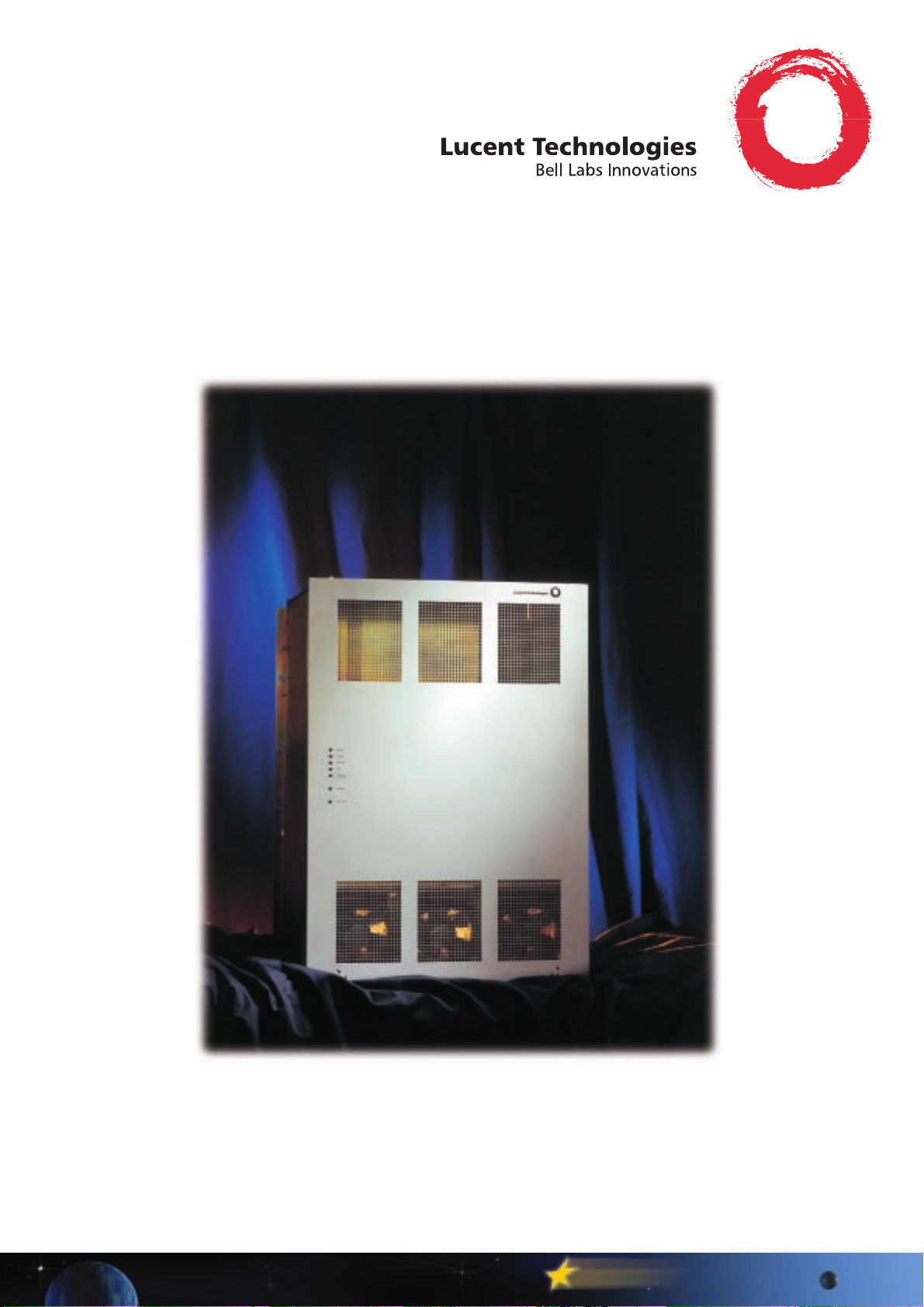
The WaveStar ADM 16/1, is
a member of the WaveStar
family of Lucent Technologies
optical networking products.
INTRODUCTION
he WaveStar ADM 16/1 is a
T
high-capacity intelligent
multiplexer and transport system
able to multiplex PDH, SDH,
SONET and EtherNet bit rates to
higher levels up to 2.5 Gbps
(STM-16). Because of this wide
range in capacity, this system is a
key element in building efficient
and flexible networks.
The main strengths of the product
are:
· Massive add/drop capacity
directly from the
STM-16 level e.g. 504 x E1,
96 x DS-3,
64 x 10/100 BASE-T, 32 x
STM-1 etc.
· Compact design (single row).
· Easy installation &
maintenance.
· Flexibility in applications.
· Advanced protection
mechanisms allowing
state-of-the-art SDH network
design.
These outstanding features make
the WaveStar ADM 16/1 one of
the most cost-effective futureproof network elements. The
system can be deployed with
other Lucent Technologies optical
networking products, making the
WaveStar ADM 16/1 one of the
main building blocks of future
SDH networks.
The WaveStar ADM 16/1 is
controlled and managed by
Lucent Technologies Integrated
Transport Management (ITM), a
user-friendly network and
element level management
system with in-service upgrade
facilities.
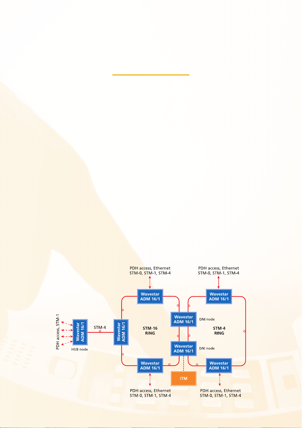
Figure 1: WaveStar ADM 16/1 Network Application
Page 3
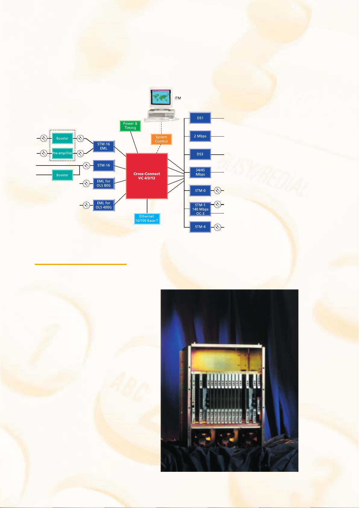
Figure 2: Basic Architecture of the WaveStar ADM 16/1
FEATURES AND BENEFITS
ne of the main features of
O
the WaveStar ADM 16/1 is
the ability to add/drop and
flexibly cross-connect directly
from the STM-16 level. Signals
that can be connected are: 1.5
(DS-1), 2 (E1), 34 (E3), 45 (DS-
3), 51.8 (STM-0), 140 (E4),
155 (STM-1/OC-3) and 622
(STM-4/OC-12) Mbps. Unique to
the system is that it supports the
advanced protection mechanisms
MS-SPRing, VC-SNC/N and Dual
Node Interconnection as well as
the conventional MSP. To reduce
overall installation and test time,
pre-fabricated cabling is used.
· Single product platform for
STM-16 and STM-4
applications.
· Single network element for
interconnection of STM-16,
STM-4 and STM-1 rings
· TransLAN-functionality
based on ML-PPP at 8 x
10/100 BASE-T for each
circuit pack.
· The system architecture allows
a broad range of applications:
add/drop, terminal, local
cross-connect.
· Support of ETSI
Synchronization Status
Message (SSM) protocol.
· AU-3 / TU-3 to AU-4
conversion.
· Full Time Slot Assignment
(TSA) for port interface signals
and Time Slot Inter-change
(TSI) for through channels.
· Support of PDH signals: E1, E3
and E4.
· Support of SONET Signals:
DS-1, DS-3, OC-3 & OC-12.
Summary of main features and
benefits:
· Protection mechanisms
supported: MS-SPRing,
SNC/N, MSP and DNI.
· VC-4, VC-3 and VC-12 crossconnect capability.
Figure 3: ADM 16/1 open shelf
Page 4

Figure 4: WaveStar ADM 16/1 Shelf in rack
Page 5

· Support of SDH signals: STM0, STM-1, STM-4 & STM-16.
· Mixing of various payload
types.
· In-shelf optical booster or
booster/pre-amplifier.
· Remote maintenance and
management by Lucent
Technologies ITM network
management system.
· Compact self-supporting single
shelf design and easy
installation.
· Duplication of critical circuit
racks in the shelf.
APPLICATIONS
he WaveStar ADM 16/1 is a
T
single product platform for
STM-16, STM-4 and STM-1
applications. Based on its
flexibility with regard to interface
units and cross-connect
capabilities, the system supports
applications for bandwidth
access, service-on-demand and
network protection.
The WaveStar ADM 16/1 can be
applied in two tiers of the
network: access & regional
networks. The system allows for
growth and changing service
needs by supporting in-service
conversions and upgrades.
Inherent to its basic design, the
WaveStar ADM 16/1 operates
equally well within fully
synchronous as well as
asynchronous environments and
provides a flexible link between
the two.
The WaveStar ADM 16/1 supports a
large variety of configurations for
various network applications (see
Figure 1):
· Terminal for point-to-point
connections.
· Ring add/drop multiplexer or
STM-4 and 16 rings.
· Access mux to DWDM, 10G,
cross-connect & SONET.
· Hub mux of STM-1 and STM-4
rings to STM-16.
· Grooming of lower-order VCs.
· PDH front-end for digital crossconnect systems.
· Single ADM 16/1 for
interconnection of STM-16,
STM-4 and STM-1 rings
(Ring Closure on tributary
side).
· TransLAN-functionality for
10/100 BASE-T Ethernet
signals.
Traffic can be protected by:
· Path protection: VC-n SNC/N.
· Section protection:
MS-SPRing, MSP.
· Dual Node Interconnection
(DNI).
PRODUCT DESCRIPTION
his flexible product resulted
T
from a big step forward in
technology. Due to the high level
of integration at the circuit pack
level, it is possible to add/drop up
to 504 x E1/DS1, 48 x E3,
64 x 10/100 BASE-T, 96 x
DS3/STM-0, 32 x E4/STM-1/OC3 or 8 x STM-4/OC-12 using only
one subrack. One rack with a
height of 2400 and 2600 mm,
can accommodate two subracks.
The heart of the WaveStar ADM
16/1 system is the CrossConnect, which has connections
with all interface cards (see
Figure 2). The Cross-Connect is
the core of the system.
It enables the flexible routing of VC-4,
VC-3 and VC-12 between:
· Aggregate and aggregate.
· Aggregate and tributary.
· Tributary and tributary.
To contribute to overall system
reliability and availability, the
Cross-Connect can be protected
by an accompanying unit. If
required, interface redundancy
can be provided. The flexible
design of the WaveStar ADM
16/1 makes it possible to place
interface units in almost any
interface slot position of the
subrack. The System Controller
(SC) unit controls all major
functions of the WaveStar ADM
16/1 and communicates with the
centralized management system
(ITM). Communication is
established via the Data
Communication Channels within
the STM-N section overhead
signals or via one of the Qinterfaces of the system. The
ITM-SC manages the WaveStar
ADM 16/1 at the element level
and the ITM-NM can manage the
system at the network level. The
ITM-Craft Interface Terminal
(ITM-CIT) is used for managing
small networks and for
maintenance purposes.
The system is synchronized by an
optionally duplicated Power and
Timing generator circuit pack.
Both 2048-kHz and 2048-kbps
synchronization interfaces are
supported. References can be
selected by and prioritized from
among the synchronization
interfaces, STM-N interfaces and
2-Mbps tributary interfaces.
Reference protection is possible
by enabling the ETS 300 417-6
compliant synchronization
message protocol which uses the
S1-byte information (SSM
support).
Page 6

Technical Data
Interfaces
Compliant with the ITU-T Recommendations:
General G.707 (includes G.708 and G.709)
Equipment G.781, G.782, G.783, G.784, G.813
Physical interface G.957 & G.691 for optics and G.703 for
Performance requirements G.823, G.825, G.826
electrical interfaces.
Mapping Structure AU4, AU-3 to TU-3, TU-3 & TU-12
(TU-11), VC-4, VC-3 and VC-12
Electrical Interfaces
1.5 Mbps a-synchronous/byte-synchronous 63 (DS-1) interfaces per circuit pack
2 Mbps a-synchronous/byte-synchronous 63 (E1) interfaces per circuit pack
34 / 45-Mbps and 45 Mbps a-synchronous 12 (E3/DS-3) interfaces per circuit pack
140 Mbps/STM-1 electrical intra-station 4 (E4/STM-1) interfaces per circuit pack
Optical Interfaces
Ethernet 10/100 BASE-T & (ML-PPP) 8 interfaces per circuit pack
STM-0 (51840 kbps) interface 12 x interfaces per circuit pack
STM-1/OC-3 (155520 kbps) interface 4 x (S-1.1 & L-1.2) interfaces per circuit
STM-4/OC-12 (622080 kbps) interface 1 x (S-4.1 & L-4.2) interface per circuit
STM-16 (2 488 320 kbps) interfaces 1 x (L-16.1, L-16.2 & L-16.3) interface
Optical Booster/Pre-amplifier 1 x (U-16.2/3) interface per circuit pack
Optical Booster 1 x (V-16.2/3) interface per circuit pack
OLS 80G (DWDM) interworking 1 x interface per circuit pack, 16 different
OLS 400G (DWDM) Interworking 1x interface per circuit pack, 80 different
Data interfaces:
Six user selectable datachannels User can select out of E1, E2, F1, F2
Standard External clock interfaces Two programmable Input/Output
pack
pack
per circuit pack
wavelengths (1549 - 1559 nm )
wavelengths (1530 - 1565 nm )
and NU bytes (4xG.703 and 2xV.11)
station clock interfaces: 2048 kHz
(G703.10) or 2048 kbps
(G703.6), 75 or 120 W
Bandwidth Management
System capacity: VC-12: 504 x 1.5 Mbps, 504 x 2 Mbps,
Complete VC-4 Cross-connecting
Higher Order Cross-connect size 64 x 64 VC-4
Lower Order Cross-connect currently 16x16 and 32 x 32 VC-4
Fixed Cross-Connect for 0x1 and 0x2 Terminal Applications
Uni & Bi-directional Cross-connecting
Broadcast connections type VC-n
VC-4-4c Continuos Concatenation
Higher Order and Lower Order broadcast functionality 1:N (N£9)
Protection access (LPT) on MS-SPRing
Scalable MS-SPRing
Drop & Continue
VC-3: 48 x 34 Mbps, 96 x 45 Mbps,
96 x STM-0,
VC-4: 32 x 140 Mbps, 32 x STM-1 or
8 x STM-4
Performance requirements
Jitter on STM-N interfaces G.813, G.825
Jitter on PDH interfaces G.823, G.783
Error Performance G.826
Performance monitoring G.784, G.826
Page 7

Performance Monitorings
Trail Termination Points Equipment
VC-12 for each DS1 and E1 port
VC-3 for each DS3, E3 and STM-0 interfaces
VC-4 for each E4 interface and on the Cross-Connect
MS-0 Multiplex Section on the STM-0 interfaces
MS-1 Multiplex Section on the STM-1 interfaces
MS-4 Multiplex Section on the STM-4 interfaces
RS-16 Regenerator Section of the 2.5 Gbps interfaces
MS-16 Multiplex Section of the 2.5 Gbps interfaces
Non-Intrusive Monitoring on VC-4, VC-3 & VC-12 trails & VC- 4- 4c
Severity setting for alarms on each TP instance
Enhancements compliant 24 hr counters Unavailable period storage
History bin: every 15 minutes (16 bins + 4 hour storage time)
Threshold reports
Every 24 hours (1 bin + 1 day storage time)
Supervision and alarms
Plug-in circuit pack Indication LED continuously on: diagnostic error
System Controller indicators/buttons:
LED indicators Power, Prompt and Deferred alarm
Push-buttons Suppress, Disconnect
CIT connector F-interfaces V.10/RS-232
Station alarm interface outputs Floating
Miscellaneous Discretes 8 inputs and 8 outputs
Q-LAN interface to connect to EMS or other Network
LED flashing: transmission signal error
Abnormal, Info, Suppressed, UseCIT,
and Disconnect
Elements
Protection and redundancy
Tributary Level Redundancy:
1:N Equipment protection on 1.5 Mbps & 2 Mbps Interface circuit packs (N= max. 8)
1+1 Equipment protection on 34/45 Mbps, 45 Mbps Interface circuit packs
1:N Equipment protection on 140/STM1e (N= max. 4)
1+1 Equipment protection on Cross-connect circuit pack and Power & Timing circuit
pack
SNC/N protection:
VC-4 level
VC-12, VC-3 level
Programmable hold-off times
Dual Node Interworking (DNI):
between two MS-SPRings
between MS-SPRing and LO-SNC protected SubNetworks
Support of VC-4-4c Concatenation
MSP:
1+1 MSP on optical STM-0 (G.783 Annex B), STM-1 (G.783 Annex A & B) and
STM-4 (G.783 Annex A & B) tributary Interface signals
1+1 MSP on optical Line Interface circuit packs STM-16 (G.783 Annex A)
MS-SPRing:
MS-SPRing in two fiber ring Add/Drop applications
Selective MS-SPRing
Cascading of protection schemes in one Network Element
Programmable hold-off times
Maximum of 50 ms switching time for all protection mechanisms
Page 8

Timing and Synchronization
Built-in oscillator Standard Accuracy 4.6 ppm acc.G.813 option 1
Built-in oscillator Stratum-3 Accuracy 4.6 ppm acc.G813 option 1,
Timing modes:
Free running mode Accuracy 4.6 ppm
Hold-over mode
Locked mode with reference to- one of the external sync. inputs
Automatic reference signal switching Compliant with ETSI ETS 300 417-6
Support of Synchronization Status Message on STM-N interfaces, 2 Mbps and at
Retiming on 2 Mbps
Stability 0.37 ppm/ first 24 hours
- one of the 2 Mbps tributary inputs
- one of the STM-N inputs
2048 kbps external clock interface
Network Management
Fully manageable by ITM-NM and ITM-SC
Local Workstation (ITM-CIT) via RJ-45
connections V.10(RS-232 compatible) / F-interface
Access to Embedded Communication Channels
via in-station Q-LAN interface G.773-CLNS1 / 10-Base-T and
ITM-CIT for small network management CIT-Q connector / V.10
10-Base-2 Interfaces
Physical design
Subrack dimensions 750 x 500 x 545 mm (H x W x D)
In accordance with ETSI
Recommendation
ETS 300 119-4 for wide racks
Rack Types 2000 mm Earthquake proof (zone 4)
2200 mm ETSI (D700) rack
2600 mm ETSI (D700) rack
Connectors-Optical Standard universal build-out optical
connector (FC/PC, SC) on the STM-4
and STM-16 interfaces
LC connectors on STM-0 and LC or SC
connectors on STM-1 interfaces
Connectors-Electrical Choice out of: SUB-D, DIN Coax, APT
Coax, Modular Jack, BT43, ISC 1.5/5.6
Connectors-Ethernet RJ-45
Station power input (Battery) -48 or -60 V DC (Range: -40,5. .. -72 V
DC)
Power Consumption 310 Watt for an average configuration
Environmental conditions
Acc. ETSI Requirement Class 3.1 Environment: 3.1 extended (3.1E)
Temperature range Humidity
Normal operation +5°C to + 45°C up to 90%
Short term operation 0°C to + 50°C up to 80%*
Storage- 25°C to + 55°C up to 100%
*Short term conditions last at most 72 hours per year during at most 15 days
EMC
EC Declaration of Conformity per ETS300 386-1 & -2: "EMC requirements for Public
Telecommunication Network Equipment" which covers:
Radiated emission EN 55022
Conducted emission EN 55022
Electro-static discharge IEC 801-2,3,4,
Radiated immunity IEC 1000-4-x series
Conducted immunity:
- Electrical fast transients IEC 1000-4-x series
- Surges IEC 1000-4-x series
- Continuous wave IEC 1000-4-x series
Compliant with LVD EN 60950
This document is for planning purposes
only, and is not intended to modify or
supplement any Lucent Technologies
specifications or warranties relating to
these products or services.
Performance figures and data quoted in
this document are typical and must be
specifically confirmed in writing by
Lucent Technologies before they become
applicable to any particular order or
contract. The company reserves the right
to make alterations or amendments to
the detailed specifications at its discretion.
The publication of information in this
document does not imply freedom from
patent or other protective rights of
Lucent Technologies or others.
WaveStar is a trademark of Lucent
Technologies Inc.
To learn more about our comprehensive
portfolio and the new WaveStar ONG
Series, please contact your Lucent
Technologies Sales Representative
or call +33 49 23 83 333 Visit our web
site at http://www.lucent-optical.com
Copyright © 1999 Lucent Technologies.
All Rights Reserved.
Printed in Holland
Lucent Technologies Inc.
Marketing Communications
Order Number: PB-025/991102
 Loading...