

Page 1

DEFINITY® Wireless Business System
9630 Series Wireless Terminal User’s Guide
555-232-701
Comcode 108468539
Issue 1
May 1999
Page 2

Page 3

Notice
While reasonable efforts were made to ensure that the information
in this document was complete and accurate at the time of printing,
Lucent Technologies
can assume no responsibility for any errors.
Changes and corrections to the information contained in this
document may be incorporated into future reissues.
Your Responsibility for Your System’s Security
You are responsible for the security of your system. Lucent
Technologies
does not warrant that this product is immune from or
will prevent unauthorized use of common-carrier telecommunication
services or facilities accessed through or connected to it. Lucent
Technologies will not be responsible for any charges that result from
such unauthorized use. Product administration to prevent
unauthorized use is your responsibility and your system
administrator should read all documents provided with this product
to fully understand the features available that may reduce your risk
of incurring charges.
Federal Communications Commission Statements
Part 15D: Unlicensed Personal Communications.
This equipment has been certified to comply with the regulations
governing unlicensed Personal Communication devices pursuant to
Subpart D of Part 15 of the FCC rules. This subpart sets the
regulations for devices operating in the 1920-1930 MHz frequency
band.
Part 68: Network Registration Number. This equipment is
registered with the FCC in accordance with Part 68 of the FCC
Rules. It is identified by FCC registration number
AS593M-13283-MF-E.
Part 68: Answer-Supervision Signaling. Allowing this
equipment to be operated in a manner that does not provide proper
answer-supervision signaling is in violation of Part 68 rules. This
equipment returns answer-supervision signals to the public switched
network when:
■ Answered by the called station
■ Answered by the attendant
■ Routed to a recorded announcement that can be
administered by the CPE user
■ This equipment returns answer-supervision signals on all
DID calls forwarded back to the public switched telephone
network. Permissible exceptions are when a call is
unanswered, a busy tone is received, or a reorder tone is
received.
Trad emarks
DEFINITY Enterprise Communications Server is a registered
trademark of Lucent Technologies
in the US and throughout the
world.
DEFINITY Communications System is a registered trademark of
Lucent Technologies
in the US and throughout the world.
Ordering Information
Call: Lucent Technologies BCS Publications Ce nter
Voice 1 800 457-1235 International Voice 317 322-6791
Fax 1 800 457-1764 International Fax 317 322-6699
Write: Lucent Technologies BCS Publications Ce nter
2855 N. Franklin Road
Indianapolis, IN 46219
Order: Document No. 555-232-701
Comcode 10846853 9
Issue 1, May 1999
For additional documents, refer to the section in “About This
Document” entitled “Related Information.”
For more information about Lucent Technologies
documents, refer
to the
Business Communications Systems Publications Catalog
(555-000-010).
You can be placed on a Standing Order list for this and other BCS
documents you may need. Standing Order will enable you to
automatically receive updated versions of individual documents or
document sets, billed to account information that you provide. For
more information on Standing Orders, or to be put on a list to
receive future issues of this document, please contact the Lucent
Technologies BCS Publications Center.
Users outside of the US and Canada should contact their local
authorized Lucent Technologies distributor if they want to order
additional copies of this document. Also, users in these countries
should send any comments on the document to their local
authorized Lucent Technologies distributor.
Disclaimer
Intellectual property related to this product and registered to AT&T
Corporation has been transferred to Lucent Technologies
Incorporated.
Lucent T e chn ologi es Fraud Interv enti on
If you suspect your are being victimized by toll fraud and you need
technical support or assistance, call the BCS Technical Service
Center Toll Fraud Intervention Hotline at 1 800 643-2353.
Comments
To comment on this document, return the comment card at the back
of the document.
Acknowledgment
This document was prepared by the
BCS Product Publications group,
Lucent Technologies
Middletown, NJ 07748-9972
Copyright © 1999 Lucent Technologies
All Rights Reserved
Printed in USA
Page 4

Page 5

Avis
Bien que tout ait été mis en oeuvre pour que les données contenues
dans ce document soient exactes et complètes au moment de
l’impression, Technologies Lucent ne peut assumer aucune
responsabilité en cas d’erreurs. Tout changement et correction aux
données de ce document seront intégrées dans les prochaines
versions.
La sécurité de votre système vous incombe
C’est à vous que revient la tâche d’assurer la sécurité de votre
système. Technologies Lucent ne garantit pas que ce produit
empêchera l’accès non autorisé à des services de
télécommunications ou à des installations auxquels il est relié ou
auxquels il donne accès. Technologies Lucent n’acceptera aucune
responsabilité relativement à tous les frais éventuels découlant
d’une telle utilisation non autorisée. Vous avez la responsabilité
d’assurer la gestion de ce produit afin d’empêcher toute utilisation
non autorisée. Le gestionnaire devrait lire tous les documents qui
l’accompagnent afin de bien comprendre les caractéristiques
disponibles pour réduire les risques de frais inattendus.
Énoncé de la Federal Communications Commission
Section 15D : Communications personnelles non
brevetées.
Cet équipement a été accrédité comme étant conforme aux
règlements qui régissent les dispositifs de communications
personnelles non brevetés en vertu de la sous-section D de la partie
15 du règlement de la FCC. Cette sous-section établit les
règlements pour les dispositifs qui fonctionnent dans la bande de
fréquence de 1920 à 1930 MHz.
Partie 68 : Numéro d’enregistrement du réseau. Cet
équipement est enregistré auprès de la FCC, conformément à la
partie 68 du règlement de la FCC et porte le numéro
AS593M-13283-MF-E de la FCC.
Partie 68 : Signaux de supervision de réponse. Permettre
à cet équipement d’être utilisé sans prévoir de signaux de
supervision de réponse est contraire au règlement de la partie 68.
Cet appareil envoie des signaux de supervision de réponse au
réseau public commuté dans les cas suivants :
■ Le poste appelé a répondu
■ La standardiste a répondu
■ Appel acheminé à un message enregistré qui peut être
géré par l’utilisateur du CPE.
■ Cet appareil retourne des signaux de supervision de
réponse pour tous les appels SDA réacheminés au réseau
téléphonique public commuté. Les exceptions acceptables
sont les suivantes : quand un appel reste sans réponse, s’il
reçoit une tonalité d’occupation ou une tonalité de
recomposition.
Marques de commerce
DEFINITY Enterprise Communications Server est une marque
déposée de Lucent Technologies aux États-Unis et partout dans le
monde.
DEFINITY Communications System est une marque déposée de
Lucent Technologies aux États-Unis et partout dans le monde.
Modalités de commande
Téléphone :Lucent Technologies BCS Publications Center
Téléphone 1 800 457-1235 International 317 322-6791
Télécopieur 1 800 457-176 4 Int ernational 317 322-6699
Courrier : Lucent Technologies BCS Publications Center
2855 N. Franklin Road
Indianapolis, IN 46219
Commander: Document Nº 555-232-701
Comcode 108468539
Version 1, Mai 1999
Pour plus de renseignements relatifs aux documents de
Technologies Lucent, consulter le document intitulé Business
Communications Systems Publications Catalog (555-000-010).
Vous pouvez, si vous le souhaitez, être ajouté à la liste de
commande permanente pour ce manuel et tous les documents BCS
dont vous avez besoin. Avec une commande permanente, vous
recevrez automatiquement les mises à jour des documents ou jeux
de documents, qui seront facturés selon les renseignements que
vous fournirez. Pour en savoir davantage sur les commandes
permanentes, ou pour faire mettre votre nom sur la liste des gens
qui recevront les prochaines versions de ce document, veuillez
communiquer avec le centre des publications BCS de Technologies
Lucent.
Les utilisateurs hors des États-Unis et du Canada sont priés de
communiquer avec le distributeur agréé de Technologies Lucent
dans leur région pour commander d’autres exemplaires de ce
document. De plus, dans ces pays, les utilisateurs sont priés
d’envoyer leurs commentaires sur le document au distributeur agréé
de Technologies Lucent de leur région.
Clause de non-responsabilité
La propriété intellectuelle associée à ce produit et enregistrée à
AT&T Corporation a été transférée à Technologies Lucent.
Prévention de la fraude de Technologies Lucent
Si vous soupçonnez être victime d’une utilisation frauduleuse des
interurbains et avez besoin d’aide ou d’assistance technique,
veuillez communiquer avec le centre d’intervention contre les
utilisations frauduleuses des interurbains du Centre de service
technique BCS au numéro sans frais 1 800 643-2353.
Commentaires
Pour nous faire part de vos commentaires au sujet de ce document,
veuillez retourner la carte qui se trouve à la fin du document.
Remerciements
Ce document a été préparé par
BCS Product Publications group,
Technologies Lucent
Middletown, NJ 07748-9972
Copyright © 1999 Technologies Lucent
Tous droits réservés
Imprimé aux États-Unis
Page 6

Page 7

Contents
Issue 1 May 1999 v
About This Book xiii
■ Introduction xiii
■ Audience xiii
■ Electromagnetic Compatability Warning xiv
Important Safety Guidelines for Users xiv
Exposure to Radio Frequency Energy xiv
Cardiac Pacemakers xiv
Hearing Aid Compatibility xv
■ Organization xv
■ Related Information xvi
■ Typographic Conventions xvi
1 Overview 1-1
■ Introduction 1-1
■ DEFINITY Wireless Busines s System 1-1
■ 9630 Series Wireless Terminal 1-1
Features and Benefits 1-4
■ Supplementary WT Equipment 1-5
■ DWBS Capacity and Coverage 1-5
2 Battery Charger 2-1
■ Introduction 2-1
■ Battery Charger Features 2-2
Extending Battery Life 2-3
■ Battery Charger Oper ati ons 2-6
Positioning the Battery Charger 2-6
Installing the Battery Charger 2-6
Inserting a Battery Pack Into the Spare
Battery Compartment 2-9
Page 8

Contents
vi Issue 1 May 1999
Removing a Battery Pack from the Spare
Battery Compartment 2-10
Inserting the WT into the Battery Charger’s
WT Cradle 2-10
Removing the WT From the WT Cradle 2-11
■ Troubleshooting the Battery Charger 2-12
■ Battery Charger Wall-Mounting Template 2-16
3 Features and Operations 3-1
■ Introduction 3-1
■ 9630 Series WT Features 3-1
Hard Key Interface 3-3
Soft Key Interface 3-3
Muting and Unmuting the WT 3-4
Volume Control Buttons 3-4
Display 3-4
Dial Pad 3-6
■ Operating the 9630 Series WT 3-7
Administering Personalized Ringing 3-7
Adjusting the Earpiece Volume 3-8
Adjusting Ringer and Warning/Notification
Tones 3-8
Activating and Deactivating the Backlight 3-8
Making Calls 3-9
Answering Calls 3-10
Activating and Deactivating the Vibrator 3-10
Activating and Deactivating Silent Mode 3-11
Transferring Calls 3-11
Conferencing Calls 3-12
Holding Calls 3-12
Ending Calls 3-12
Dropping Calls 3-12
Locking and Unlocking the WT 3-13
Redialing Calls 3-15
Page 9

Contents
Issue 1 May 1999 vii
Displaying Service Information 3-16
■ Fastening the Belt Clip 3-17
■ Removing the Belt Clip 3-18
4 Audible Information Tones and
Error Messages 4-1
■ Introduction 4-1
■ Incoming Call Ring Patterns 4-1
■ Error Beep 4-2
■ Warning Tone 4-2
■ User-Level Error Messages 4-3
A Safety Instructions A-1
■ Introduction A-1
■ Using the Product A-1
■ Maintaining the WT A-3
B Specifications B-1
■ Introduction B-1
■ Operating Temperatures B-1
■ Storage Temperatures B-1
GL Glossary GL-1
Page 10

Contents
viii Issue 1 May 1999
IN Index IN-1
Page 11

Figures
Issue 1 May 1999 ix
1 Overview
1-1. 963 0 Ser ie s W i reles s Terminal 1-3
2 Battery Charger
2-1. Battery Charger for the 9630 Series WT 2-2
2-2. Inserting Power Cord into the Battery
Charger 2-7
2-3. Sliding Battery Charger into Place 2-8
2-4. Plugging in AC Adapter 2-9
2-5. Inserting Battery Pack Into Spare
Battery Compartment 2-10
2-6. Inserting WT Into the Cradle 2-11
2-7. Battery Charger Wall-Mounting Template 2-16
3 Features and Operations
3-1. 9630 Series WT 3-2
3-2. Icons for the 9630 Series WT 3-5
3-3. Fastening the Belt Clip 3-17
3-4. Removing the Belt Clip 3-18
Page 12

Figures
x Issue 1 May 1999
Page 13

Tables
Issue 1 May 1999 xi
1 Overview
1-1. 9630 Series WT Features and Benefits 1-4
2 Battery Charger
2-1. LED Indicators 2-3
2-2. Battery Pack Refresh Cycle 2-4
2-3. Battery Charger Problems and
Possible Solutions 2-12
4 Audible Information Tones and Error
Messages
4-1. User-Level Error Mess age s and
Corrective Actions for the WT 4-3
Page 14

Tables
xii Issue 1 May 1999
Page 15

Issue 1 May 1999 xiii
About This Book
Introduction
The DEFINITY®
Wireless Business System 9630 Series Wireless Terminal User’s
Guide
explains how to use, maintain, and troubleshoot your DEFINITY Wireless
Business System (DWBS) 9630 Series Wireless Terminal (WT).
Audience
This guide is intended for anyone using the DWBS 9630 Series WT.
Page 16

About This Book
xiv Issue 1 May 1999
Electromagnetic Compatability
Warning
Important Safety Guidelines for Users
For safe and efficient operation of your DWBS 9630 Series WT, observe these
guidelines.
Your WT is a radio transmitter and receiver. When the battery is installed, the WT
is on and it receives and also sends out radio frequency (RF) energy. The WT
operates in the frequency range of 1920-1930 MHz. Your handheld WT uses the
digital Time Division Multiple Access (TDMA) mode; the power is transmitted in
bursts at a 100 Hz-pulsed repetition rate. The peak envelope transmit power is
100 mW or less.
Exposure to Radio Frequency Energy
The design of your WT complies with the latest safety levels from the Institute of
Electrical and Electronic Engineers (IEEE) and the American National Standards
Institute (ANSI) with respect to human exposure to RF energy. Of course, if you
would like to limit RF exposure even further, you may choose to control the
duration of your calls.
Most electronic equipment, such as equipment in hospitals, is shielded from RF
energy. However , RF energy from wireless telephones may affect some electronic
equipment.
Cardiac Pacemakers
The Health Industry Manufacturers Association recommends that a minimum
separation distance of six inches be maintained between a handheld WT and a
pacemaker to avoid potential interference with the pacemaker. Also, the following
guidelines are recommended.
!
WARNING:
Always keep the WT more than six inches from the pacemaker whenever
the battery is in the WT.
S'il y a une pile dans le SF, toujours le garder à plus de six pouces du
pacemaker.
!
WARNING:
Do not carry the WT in a breast pocket.
Ne pas porter le SF dans une poche-poitrine.
Page 17

Organization
Issue 1 May 1999
xv
!
WARNING:
Use the ear opposite the pacemaker to minimize the potential for
interference.
Utiliser l’oreille du côté opposé de celui où se trouve le pacemaker pour
minimiser les risques de parasites.
If you suspect that interference is taking place, take the battery out of your WT
immediately.
Hearing Aid Compatibility
Although the DWBS WT is compatible with inductively coupled hearing aids, you
should consult your physician or hearing aid manufacturer to determine if your
hearing aid is adequately shielded from external RF energy. The operation of
inadequately shielded medical devices may be adversely affected when a
portable WT is operating in close proximity.
Organization
This rest of the document is organized as follows:
■ Chapter 1, “Overview,” provides an overview of the DWBS, the 9630
Series WT, and the battery charger.
■ Ch apter 2, “Battery Charger,” provides battery charger and general care
instructions to ensure dependable and uninterrupted service.
■ Chapter 3, “Features and Operations,” provides information and
diagrams needed to make full use of the DWBS 9630 Series WT.
■ Chapter 4, “Audible Information Tones and Error Messages,” identifies
and describes the DWBS 9630 Series WT incoming call ring patterns, error
beeps, error tone, confirmation tone, and warning tones. The chapter also
identifies and describes in-line errors and user-level error messages for the
WT .
■ Appendix A, “Safety Instructions,” discusses the appropriate safety
instructions for the 9630 Series WT and the charger.
■ Appendix B, “Specifications,” provides various specifications for the
DWBS.
A glossary and index are also included.
Page 18

About This Book
xvi Issue 1 May 1999
Related Information
Other books in the DWBS series are as follows:
■
DEFINITY ECS Interface for the DEFINITY Wireless Business System
Guide, 555-232-108
■
DEFINITY Wireless Business System Installation and Test, 555-232-102
■
DEFINITY Wireless Business System Maintenance, 555-232-103
■
DEFINITY Wireless Business System Site Planning, 555-232-601
■
DEFINITY Wireless Business System 9630 Series Wireless Terminal Quick
Reference Card, 555-232-702
Typographic Conventions
The following typographic conventions are used in this book to convey information
consistently and quickly.
■
This typeface
is used for references to titles of other information and for
emphasis within other typefaces.
■ This typeface emphasizes key words to help clarify meaning in a sentence
or to call attention to a distinction.
■ The following note icon identifies additional information pertinent to the text
preceding it.
NOTE:
Page 19

Issue 1 May 1999 1-1
1
Overview
Introduction
This chapter provides an overview of the following:
■ DEF INITY Wireless Business System (DWBS)
■ 9630 Series Multiline Wireless Terminal (WT), including its features and
benefits
■ Battery charger for the WT
■ DWBS capacity and coverage
DEFINITY Wireless Business System
The DWBS is a wireless telecommunications system that offers mobility around
the workplace. It integrates wireless capabilities into the DEFINITY Enterprise
Communications Server
®
(ECS). The DWBS radio components operate in the
unlicensed part of the Personal Communications System (PCS) band (1920
MHz-1930 MHz); this negates the need to obtain a license to use the DWBS.
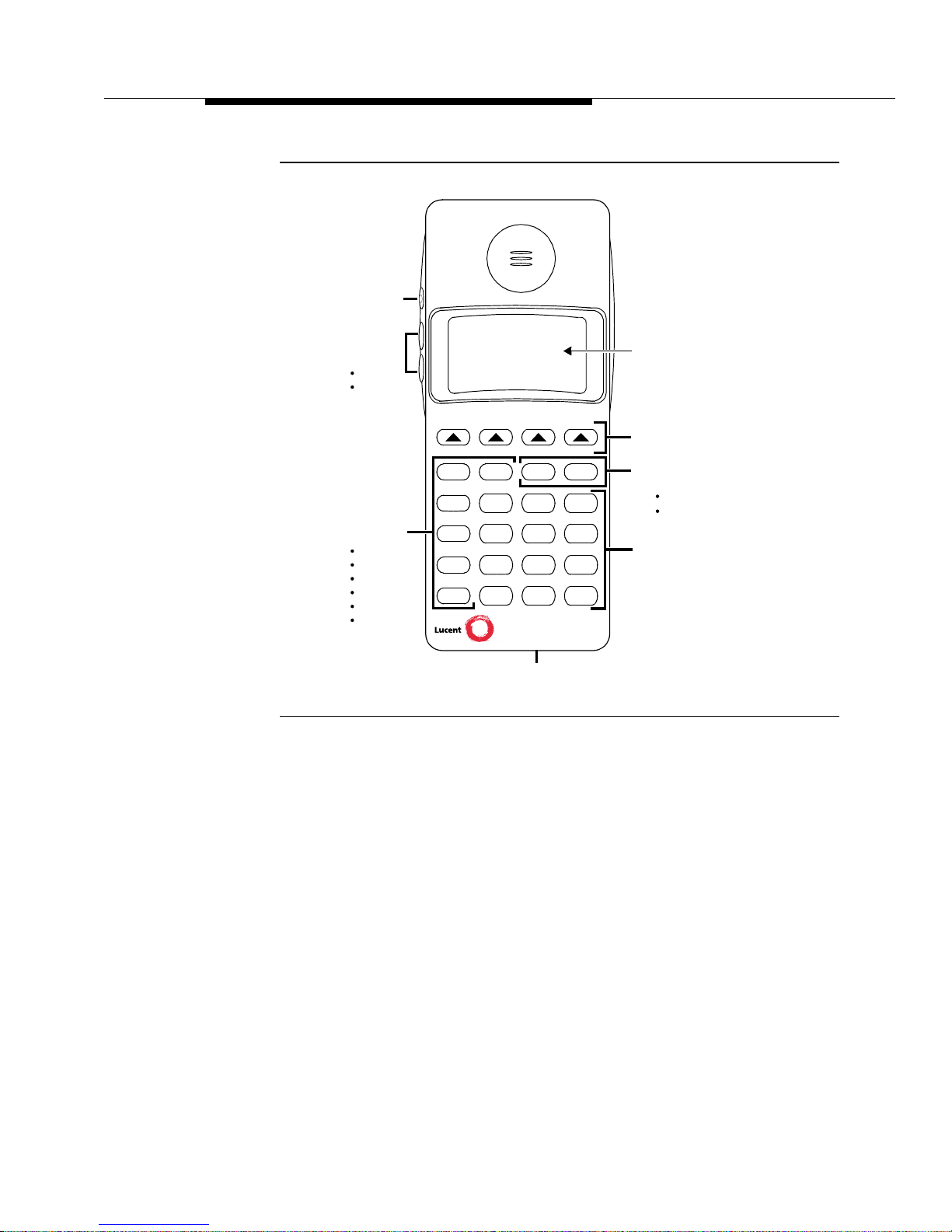
9630 Series Wireless Terminal
The 9630 Wireless Terminal (WT) is a pocket-size, portable phone that provides
wireless mobility as well as access to full business features and many DEFINITY
ECS features.
The 9630 Series WT provides either two or three call appearances and a four-line
by 16-character liquid crystal display (LCD) plus a row of icons indicating the
Page 20

Overview
1-2 Issue 1 May 1999
status of the following: message waiting, signal strength, lock, vibrator, battery,
silent, mute, and next.
The 9630 Series WT contains the following hard keys (buttons) on the keypad:
On/Off, Redial, Menu, Next, Silent, Conf, Trans, and Hold; it also contains a Mute
button and two volume control buttons on the side. In addition, the WT contains a
dial pad and four soft key buttons.
The 9630 Series WT is not physically connected by a cord to the DEFINITY ECS
or any other DWBS component. Instead, the WT is wireless and communicates
via a radio link to a network of Wireless Fixed Bases (WFBs), which in turn
connect the WT to the DEFINITY ECS. The 9630 Series WT is designed to be
compatible with existing and future releases of the DWBS.
NOTE:
The following figure shows the 9630 Series WT. Chapter 3 of this guide
describes the 9630 Series WT in detail and contains instructions on how to
use the WT.
Page 21
9630 Series Wireless Terminal
Issue 1 May 1999
1-3
Figure 1-1. 9630 Series Wireless Terminal
Wireless
*
#
On/Off
Soft Keys
Dial Pad
Display
Terminal
Silent
Conf
Trans
Hold
123
ABC DEF
456
JKL MNO
7
89
TUV WXYZ
0
OPER
Redial Menu Next
GHI
PQRS
Hard Keys for
Menu
Next
Volume
Control
Menu Control
Hard Keys
for Call
On/Off
Redial
Silent
Conf
Trans
Hold
Mute
9630
Headset Jack
Control
Management
Ringer
Earpiece
Page 22

Overview
1-4 Issue 1 May 1999
Features and Benefits
The DWBS 9630 Series WT provides features and benefits that take the following
into account:
■ Noisy and relatively inhospitable environments
■ Durability and reliability
Table 1-1. 9630 Series WT Features and Benefits
Features Benefits/Descriptions
Fixed feature buttons Provides one-button access to frequently-used
functions, including conference, transfer, redial,
mute, silent, and hold.
Three call
appearances
Provides the ability to place and receive multiple
calls.
Louder ringer and
receiver volume
For use in noisy environments.
Noise-Canceling
Microphone
Minimizes background noise and therefore provides
a quieter call for the listener in noisy environments.
Vibrator (Silent Alert) Provides a vibrating, silent alert for incoming calls
that can be turned on and off from the menu.
Built-in attachments for
belt clip and lanyard;
carrying case included
with the set
Provides carrying options. Secure s the WT in
environments where the WT may be dropped from a
height greater than for a standing position.
Extended battery life Provides more than eight hours of talk time and more
than 100 hours of idle time.
Standard headset
adapter
Provides hands-free operation.
Backlit display Allows using the WT in poorly lit conditions.
Personalized Ringer Valuable in environments where WT users are in
close proximity to each other because it allows
individual users to program a “specified” ring to allow
them to know that an incoming call is being received
on their line.
Impact resistant Designed to withstand multiple drops from a standing
position.
Headset May be used for hands-free operation.
Page 23

Supplementary WT Equipment
Issue 1 May 1999
1-5
Supplementary WT Equipment
A DWBS battery charger, a battery, and additional battery packs are available with
each WT.
The DWBS battery charger is a desktop charger; however, the charger can be
mounted on either a wall or desktop. The charger charges a fully discharged
battery in less than one and one-half hours.
Your 9630 Series WT must be charged before you use it for the first time. All
instructions and a diagram for this process are provided in Chapter 2, “Battery
Charger.”
DWBS Capacity and Coverage
The DWBS 9630 Series WT is designed to provide the highest quality of mobility
service that wireless technology permits. Your system is designed for full
functionality and excellent voice quality throughout the areas where service is
provided as defined by your company’s communications director.
Since this system uses RF signals for the communications channel to your WT,
there are situations when you may notice a difference in service from your wired
voice terminal. These situations may exist because it is difficult, if not
economically unreasonable, to provide flawless coverage in all areas (for
example, behind large metal storage or file cabinets, in a vault, or in a cold
storage locker). In many of these cases, your company decided, at the time your
system was designed, that perfect service in areas such as these is not
warranted.
While the DWBS features the highest capacity possible within the Federal
Communications Commission (FCC) regulations and Personal Wireless
Telecommunications (PWT) standards, the number of radio channels available is
limited and dependent on the amount of radio equipment installed. To put this in
perspective by relating it to your private branch exchange (PBX), a central office
(CO) trunk (dial 9) is not provided for every user; in fact, a ratio of one CO trunk
per 10 users is common. Likewise, with DWBS, a radio channel is not available for
each user throughout your defined coverage area. Therefore, if a large number of
users attempts to use the system by either making or receiving calls at the same
time and in the same area, a radio channel may not be available; this results in a
“No Channel Available” condition. An example of this would be if a large number
of users were to attend a training course on the DWBS and, after the pocket
phones were distributed at the end of the class, more users attempted to call each
other than is allowed by the number of radio channels available in the area.
As you move about your premises, the system may not be able to find an idle
radio channel to allow you to continue an active call because the area you are
entering is very busy. This may result in a degraded connection, even when you
are in an area that usually provides good coverage. Most likely, the difficulty is
Page 24

Overview
1-6 Issue 1 May 1999
capacity-related; however, an intermittent system malfunction could occur. If the
problem is transient, it is a capacity issue and does not require any action on your
part. If the area usually has good coverage and the problem persists, a portion of
your system may not be functioning correctly. In either case, we recommend
reporting the problem to your telecommunications group or system
administrator.
Your understanding and consideration of this information will help us and your
telecommunications group satisfy your mobility communications requirements.
Page 25

Issue 1 May 1999 2-1
2
Battery Charger
Introduction
The battery quick charger charges battery packs in both the spare battery
compartment and in the WT when it is placed into the WT cradle. If both are
present at the same time, charging in the spare battery compartment is
suspended until the battery pack in the WT is fully charged. New batteries
sometimes take up to three charge/refresh cycles to reach their maximum
performance. Charge/Refresh cycling is described in the “Extending Battery Life”
section in this chapter.
The battery for the 9630 Series WT generally provides 12 hours of talk time and
120 hours of standby time. To extend WT usage beyond this capability, you can
purchase an extra battery pack and store it in the charger so that you always have
a charged battery pack to switch to, if necessary.
This chapter describes the battery charger and explains how to use battery packs
properly.
Page 26

Battery Charger
2-2 Issue 1 May 1999
Figure 2-1. Battery Charger for the 9630 Series WT
Battery Charger Features
The battery charger offers these features:
■ Spare battery compartment refreshes the battery pack automatically by
fully discharging the pack before recharging it. This process reduces or
eliminates the potential for “memory” effect. Memory effect reduces a
battery’s capacity, and it occurs over time when you repeatedly recharge a
battery before it is fully discharged.
■ WT cradle charges a battery pack in the WT.
■ REFRESH button, when pressed, refreshes the WT battery pack in the WT
cradle by fully discharging the battery pack before recharging it.
NOTE:
The REFRESH button is disabled if the WT has already undergone a
discharge cycle. This prevents accidentally charging or discharging a
charged battery pack.
■ REFRESH LED and the HANDSET LED light up when the REFRESH
button is pressed, and they stay lit until the battery pack finishes
discharging.
■ HANDSET LED, when lit, indicates that the WT battery pack is installed in
the WT and that the WT is in the WT cradle.
■ Spare compartment recognizes a charged battery pack and, therefore, it
does not discharge a spare pack if power is interrupted.
■ SPARE LED, when lit, indicates that a battery pack is in the spare battery
compartment.
REFRESH Button
REFRESH LED
WT Cradle Battery Contacts
HANDSET LED
SPARE LED
WT Cradle
“Battery Charge State Label”
Spare Battery
Compartment
Battery Contacts
Spare Battery
Compartment
Page 27

Battery C harger Features
Issue 1 May 1999
2-3
■ Color of the battery charger’s LEDs indicates the state of the corresponding
battery pack, as shown in the following table:
NOTE:
Before you use the 9630 Series WT for the first time, the battery pack must
be charged. New batteries sometimes take up to three charge/refresh cycles
to reach their maximum performance. Refer to the “Extending Battery Life”
section for details.
* If steady orange for more than eight hours, replace the battery.
Extending Battery Life
The battery charger charges a battery pack in the WT if you simply insert the WT
into the battery charger’s WT cradle; however, the refresh process fully
discharges the battery pack before recharging it, thereby ensuring the best
possible charge and the longest talk time.
Table 2-1. LED Indicators
Battery charger
LED shows...
If, for the SPARE LED,
the battery pack in the
spare battery
compartment...
If, for the HANDSET
LED, the battery pack
in the WT...
If, for the
REFRESH LED,
the Refresh
button was
pressed, and the
WT battery pack...
Steady orange* Is charging Is charging N/A
Steady green Has completed a fast
charge
Has completed a fast
charge
N/A
Flashing green
(see the
troubleshooting
section later in
this chapter)
Temperature is slightly
outside of the normal
changing temperature
range, or voltage is too
low in battery pack
Temperature is out of
range, or voltage is
too low in battery pack
N/A
Flashing red
(see the
troubleshooting
section later in
this chapter)
Has one of the
following problems:
--- Is not seated
properly in the charger
--- Has dirty contacts
--- Temperature
exceeds normal
changing temperature
range
--- Is defective
Has one of the
following problems:
--- Is not seated
properly in the charger
--- Has dirty contacts
--- Temperat ure
exceeds normal
changing temperature
range
--- Is defective
N/A
Steady red Is discharging Is discharging Is discharging
Page 28

Battery Charger
2-4 Issue 1 May 1999
“Memory effect” reduces a battery's capacity. This condition can occur if you
repeatedly recharge a battery pack before it is fully discharged. Nickel metal
hydride batteries also experience “memory;” therefore, it is recommended that
you refresh your battery pack at least once a week.
The following table shows how long battery refreshing takes; this depends on how
much charge is left in the battery pack when you insert it into the charger and
press the REFRESH button:
Note that your WT consumes power both during talk time (when the WT is on a
call) and during standby time (when the WT is not on a call). At full charge, the WT
battery provides approximately 8 hours of talk time and from 60 to 80 hours of
standby time. As a guideline, you can expect a one hour reduction in talk time for
every eight hours of standby time. Similarly, you can expect an eight hour
reduction in standby time for every hour of talk time.
It is highly recommended that you purchase a second battery pack to use as a
spare. With the spare battery pack in the spare battery compartment of the battery
charger, you are assured of always having a fresh, usable battery pack.
Follow these steps to ensure an uninterrupted supply of power to your 9630
Series WT:
■ If you have only one battery pack, be sure to refresh it at least once a
week. You can refresh the pack by doing the following:
— Placing it into the spare battery compartment of the battery charger.
— Leaving it in the WT, placing the WT into the WT cradle of the
battery charger, and pressing the REFRESH button.
■ If you have two battery packs, exchange the packs between the WT and
the spare battery compartment at least once a week so that each battery
pack is automatically refreshed. (Alternate the battery packs even if the WT
battery never flashes the Battery icon in the WT display to indicate a low
battery condition.)
■ The average life for the battery pack is approximately one year; this
assumes that the battery is discharged and charged once a day, and not
used or abused outside the appropriate temperature range. If the battery
packs are discharged and charged twice a day, the life expectancy is
approximately six months.
Table 2-2. Battery Pack Refresh Cycle
Battery Pack
Charge State Discharge Time Recharge Time Total Time
Low charge
(Battery icon is lit)
0.5 hours 1.5 hours 2 hours
Full charge 2.5 hours 1.5 hours 4 hours
Page 29

Battery C harger Features
Issue 1 May 1999
2-5
NOTE:
Depending on the level of memory effect for the battery pack, it is
sometimes necessary to refresh the battery pack two or three times, as
follows. (This also applies to new batteries and to batteries that have not
been used for a long time.)
Insert the battery pack into the spare battery compartment of the battery
charger and leave it there until the SPARE LED is steady green. Thereafter,
remove the battery pack from the charger; then, reinsert it and leave it until
the SPARE LED is steady green for a second time.
Or, with the battery pack in the WT, insert the WT into the WT cradle, press
REFRESH, and leave it there until the HANDSET LED is steady green.
Remove the WT from the WT cradle; then, reinsert it, press REFRESH
again, and leave it until the LED is steady green a second time. If necessary,
repeat this process a third time.
Page 30

Battery Charger
2-6 Issue 1 May 1999
Battery Charger Operations
This section explains how to choose a location for the battery charger, how to
install it, and how to insert and remove a battery pack.
Positioning the Battery Charger
You can place the battery charger on a desk or you can mount it on a wall. Before
you install the battery charger, do the following:
■ Locate the battery charger within 5 ft (1.6 m) of a properly grounded
two-prong electrical outlet that is not controlled by an ON/OFF switch.
■ If your comm unicat ions syst em uses an uninte rrupt able powe r supply, such
as a backup generator, you may want to connect the battery charger to that
power supply.
■ Do not locate the battery charger where it would be exposed to direct
sunlight or water.
!
WARNING:
Do not short-circuit or break the battery housing. (This may cause the
battery to overheat or smoke.) Do not burn or puncture the battery.
Like other batteries of this type, if it is burned or punctured, the
battery cell contents could spill onto the skin and cause irritation. Do
not dispose of the pack in household garbage. For information about
recycling or proper disposal, consult your local solid waste (garbage)
collection or disposal organization.
Installing the Battery Charger
NOTE:
If you are wall-mounting the battery charger, follow Steps 1 through 7. If you
are desk-mounting the battery charger, follow only Steps 1, 5, and 7.
1. Check to make sure the battery charger’s AC adapter is unplugged from
the wall outlet before continuing. If you are desk-mounting, skip to Step 5.
2. To wall-mount, place the battery charger’s wall-mounting template
(presented later in this chapter) against the wall. Choose a location backed
by a wooden stud (if unavailable, use toggle bolts instead of the supplied
wood screws). Hold the template straight; use a level if needed. If the
charger is not level, the battery pack may not make proper contact with the
charger.
3. Mark the locations for the two wall-mounting screws, and then remove the
template from the wall. Lightly tap a nail into the wall to start the holes.
Page 31

Battery Charger Operations
Issue 1 May 1999
2-7
4. Place the screw through the wall spacers so that the screw head nests in
the indentation on the spacer. Start the screws; screw them in until the wall
spacers rest against the wall.
5. Insert the AC adapter power cord into the battery charger. See the
following figure. If you are desk-mounting the battery charger, skip to Step
7.
Figure 2-2. Inserting Power Cord into the Battery Charger
6. Place the keyhole-shaped openings in the back of the battery charger over
the screw heads and wall spacers; then, slide the battery charger
downward to lock it into place. See the following figure.
Page 32

Battery Charger
2-8 Issue 1 May 1999
Figure 2-3. Sliding Battery Charger into Place
Page 33
Battery Charger Operations
Issue 1 May 1999
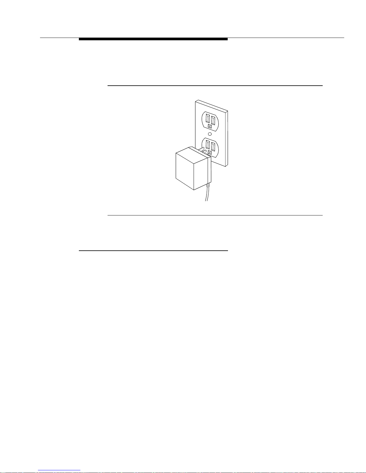
2-9
7. Plug the AC adapter into a properly grounded two-prong wall outlet
that is not controlled by an ON/OFF switch. See the following figure.
Figure 2-4. Plugging in AC Adapter
Inserting a Battery Pack Into the Spare Battery
Compartment
Slide the battery pack into the spare battery compartment until it is firmly seated
with the back of the battery pack against the back of the spare battery
compartment. Do not force the battery pack down. The battery pack should slide
easily into the slot.
Correct positioning of the battery pack in the charger is important to ensure proper
charging. The bottom end of the battery pack has two small round holes that align
with two guide pins on the bottom of the spare battery compartment. Whenever a
battery pack is positioned correctly in the spare battery compartment, the SPARE
LED on the front of the battery charger lights.
The spare battery compartment has a vertical ridge on each side that serves as a
“guide rail” for positioning the battery pack.
Page 34

Battery Charger
2-10 Issue 1 May 1999
Figure 2-5. Inserting Battery Pack Into Spare Battery Compartment
Removing a Battery Pack from the Spare Battery
Compartment
To remove a battery pack from the spare battery compartment of the charger, lift
the battery pack up and out.
Inserting the WT into the Battery Charger’s WT
Cradle
Correct positioning of the WT in the charger is important to ensure proper
charging.
1. Position the WT (with the battery pack attached) so that the two small
round holes in the bottom of the WT fit over the two guide pins on the
bottom of the WT cradle.
2. Rock the WT back into the cradle until it is firmly seated with the back of the
WT battery pack against the back of the WT cradle.
Whenever the WT has been inserted correctly, the HANDSET LED lights.
WT Cradle
SPARE LED
Vertical Guide Rail
Spare Battery
Compartment
Vertical Guide Rail
Spare Battery
Pack Guide Pin
Battery Charger
Contacts
Spare Battery Pack
Page 35

Battery Charger Operations
Issue 1 May 1999
2-11
Figure 2-6. Inserting WT Into the Cradle
Removing the WT From the WT Cradle
To remove the WT from the WT cradle, lift it out.
Guide Pins
HANDSET LED
Page 36

Battery Charger
2-12 Issue 1 May 1999
Troubleshooting the Battery Charger
The following table identifies possible battery charger problems and proposed
solutions.
Table 2-3. Battery Charger Problems and Possible Solutions
Symptom Possible Causes Possible Solutions
No LEDs on the
battery charger
light.
Battery charger is
plugged into an
electrical outlet
controlled by a switch
and the switch is
turned off.
Plug the battery charger into an
outlet not controlled by a
switch.
HANDSET LED on
the battery charger
does not light when
WT is placed into
battery charger.
WT is not seated
properly in the battery
charger’s WT cradle.
Reseat the WT in the battery
charger’s WT cradle.
Charger AC adapter
is not plugged in.
Check that the charger power
cord is plugged into the charger
and into an electrical outlet that
is not controlled by a wall
switch.
Contacts in the WT
cradle or on the
battery pack are dirty.
1. Verify that there are no
obstructions on the WT or
battery charger contacts.
2. Unplug the charger and
clean the contacts with a soft
eraser.
3. Clean the WT contacts with
a soft eraser.
The battery pack is
defective.
If you have a fully charged
spare battery pack, use it to
replace the battery pack in the
WT.
1. Place the questionable
battery pack into the battery
charger’s spare battery
compartment.
2. Wait one minute. If the
SPARE LED flashes red, order
a new batt ery pack, or replace
it through maintenance.
Page 37

Troubleshooting the Battery Charger
Issue 1 May 1999
2-13
SPARE LED on WT
flashes green.
Temperature is either
too hot or too cold.
The battery has been
drained below
operating levels.
1. If the battery pack is too
cold, allow the pack to warm to
room temperature.
2. If the battery pack is too hot,
allow the pack to cool to room
temperature.
3. Allow the charger to bring
the voltage up. When the
appropriate level of voltage is
reached, the SPARE LED turns
orange; this indicates that the
charger is fast charging.
HANDSET LED
flashed red.
The contacts in the
WT cradle or on the
battery pack are dirty.
1. Verify that there are no
obstructions on the WT or
battery charger contacts.
2. Unplug the charger and
clean the contacts with a soft
eraser.
3. Clean the battery pack
contacts with a soft eraser.
WT is not seated
properly in the battery
charger’s WT cradle.
Reseat the WT in the battery
charger’s WT cradle.
Battery pack
temperature exceeds
normal operating
temperature range.
Remove and allow the battery
pack to either warm or cool to
the normal operating
temperature. If the LED flashes
red during repeated change
cyles, the battery pack may be
defective.
Battery pack is
defective.
1. Place the battery pack into
the battery charger’s spare
battery compartment.
2. Wait one minute. If the
SPARE LED flashes red, order
a new batt ery pack, or replace
it through maintenance.
Table 2-3. Battery Charger Problems and Possible Solutions — Continued
Symptom Possible Causes Possible Solutions
Page 38

Battery Charger
2-14 Issue 1 May 1999
SPARE LED on
battery charger
does not light when
the battery pack is
placed into the
spare battery
compartment.
Battery pack is not
seated properly in the
spare battery
compartment.
Reseat the battery pack in the
battery charger’s spare battery
compartment.
The contacts on the
battery pack or in the
spare battery
compartment are
dirty.
1. Verify that there are no
obstructions on the battery
pack or battery charger
contacts.
2. Unplug the charger and
clean the contacts with a soft
eraser.
3. Clean the battery pack
contacts with a soft eraser.
Battery pack is
defective.
1. Insert the questionable
battery pack into the WT and
place the WT into the WT
cradle.
2. Wait one minute. If the LED
flashes red, order a new
battery pack, or replace the
pack through maintenance.
Table 2-3. Battery Charger Problems and Possible Solutions — Continued
Symptom Possible Causes Possible Solutions
Page 39

Troubleshooting the Battery Charger
Issue 1 May 1999
2-15
SPARE LED on the
battery charger
flashes red.
Contacts on the
battery pack or in the
battery charger’s
spare battery
compartment are
dirty.
1. Verify that there are no
obstructions on the battery
pack or battery charger
contacts.
2. Unplug the charger and
clean the contacts with a soft
eraser.
3. Clean the battery pack
contacts with a soft eraser.
Battery pack is not
seated properly in the
spare battery
compartment.
Reseat the battery pack in the
battery charger’s spare battery
compartment.
Battery pack
temperature exceeds
normal operating
temperature range.
Remove and allow the battery
pack to either warm or cool to
the normal operating
temperature. If the LED flashes
red during repeated change
cyles, the battery pack may be
defective.
Battery pack is
defective.
1. Insert the battery pack into
the WT and place the WT into
the battery charger’s WT
cradle.
2. Wait one minute. If the
HANDSET LED flashes red,
order a new battery pack, or
replace the pack through
maintenance.
Table 2-3. Battery Charger Problems and Possible Solutions — Continued
Symptom Possible Causes Possible Solutions
Page 40

Battery Charger
2-16 Issue 1 May 1999
Battery Charger Wall-Mounting
Template
Use the following template to position the screws for mounting your 9630 Series
WT battery ch arger:
1. Cut out the template.
2. Using tape and level, lightly affix the template to the wall where you want to
attach the battery charger. If possible, choose a location that positions at
least one of the screw holes over a wall stud.
3. Mark the wall.
4. Position a wall spacer on each of the two wood screws provided, and insert
the screws into the wall as far as they will go at the places you marked.
NOTE:
If you cannot locate a wall stud for one of the screws, use toggle bolts or
another type of hollow-wall fastener. Be sure to place the wall spacers on
the screws before inserting them permanently.
Figure 2-7. Battery Charger Wall-Mounting Template
1.5 inches
(3.81 cm)
center to
center
Page 41

Issue 1 May 1999 3-1
3
Features and Operations
Introduction
This chapter provides information needed to make full use of your 9630 Series
Wireless Terminal (WT). The first portion of this chapter provides a detailed
description and diagram of the WT . The second section is presented in a “how to”
format and focuses on feature identification and access.
9630 Series WT Features
The DEFINITY ECS 9630 Series WT is a portable multiple call appearance
wireless voice terminal with a display. It is a small (6 in x 2.4 in x 1.2 in),
lightweight (approximately 0.55 lbs with the battery) WT that requires no external
antenna. As shown on the next page in Figure 3-1, the 9630 Series WT has a
four-line by 16-character display plus one row of icons, four soft keys for menu
item interface, two hard keys for display control, and six hard keys for call
management. Each of these features is explained in the following pages.
Among its many benefits, the 9630 Series WT includes the following essential
business features normally found only on a wired desk phone. The “Operating the
9630 Series WT” section in this chapter gives specific instructions for these
features.
■ Conference — allows you to add additional people to your telephone call.
■ Transfer — allows you to transfer a call to another phone number.
■ Drop — allows you to disconnect the last person added to a conference
call.
■ Hold — allows you to place a call on hold.
■ Redial — allows you to dial the previous number dialed from the key pad.
Page 42

Features and Operations
3-2 Issue 1 May 1999
■ Silent — allows you to turn off audible ringing signals and tones.
■ Mute — allows you to turn off a terminal’s microphone.
Figure 3-1. 9630 Series WT
In general, the 9630 Series WT has the following features:
■ Hard key interface
■ Soft key interface
■ Ringer/volume control buttons
■ Display
■ Dial pad
■ Low battery indicator
■ Vibrator
Wireless
*
#
On/Off
Soft Keys
Dial Pad
Display
Terminal
Silent
Conf
Trans
Hold
123
ABC DEF
456
JKL MNO
7
89
TUV WXYZ
0
OPER
Redial Menu Next
GHI
PQRS
Hard Keys for
Menu
Next
Volume
Control
Menu Control
Hard Keys
for Call
On/Off
Redial
Silent
Conf
Trans
Hold
Mute
9630
Headset Jack
Control
Management
Ringer
Earpiece
Page 43

9630 Series WT Features
Issue 1 May 1999
3-3
■ Headset connector
■ Mute
Hard Key Interface
The 9630 Series WT has several hard keys. Hard keys are buttons with labels and
functions that do not change. The WT has the following hard keys.
Hard Keys for Menu Control
The hard keys for menu control include the following:
■ Menu — to access local control functions and soft key mode (see the “Soft
Key Interface” section).
■ Next — to access soft key features and calling screens
and provide access to the following features: Vibrator, Lock,
Backlight (of the display), Personalized Ringing, and Service Information.
Hard Keys for Call Management
The hard keys for call management include the following:
■ On/Off — to start and end calls
NOTE:
This hard key does not turn the power on and off.
■ Redial — to dial the previous number dialed from the key pad
■ Hold — to place calls on hold
■ Silent — to turn off audible ringing signals and tones
■ Conf (Conference) — to create a conference call
■ Trans (Transfer) — to transfer a call to another extension
Soft Key Interface
The 9630 Series WT has a row of four soft keys located immediately below the
display. Soft keys are buttons with preprogrammed labels and functions that can
change dynamically as you perform functions and make selections. Soft keys
provide access to calling and local functions, and they are intended to provide a
user-friendly interface to additional functionality. Available menu functions include
Vibrator, Lock, Backlight (of the display), Personalized Ringing, and Service
Information.
The soft keys are marked as follows:
Menu Next
Page 44

Features and Operations
3-4 Issue 1 May 1999
Because each soft key can have multiple functions, the bottom row on the display
is used for displaying associated soft key function labels. You can access several
features by pressing and . (See the previous figure and also the
“Operating the 9630 Series WT” section in this chapter.)
NOTE:
Whenever the 9630 Series WT is in menu mode, DEFINITY ECS messages
associated with an incoming alerting call override the current display state of
the WT. If the incoming call is ignored, the original soft key display state
returns.
Muting and Unmuting the WT
NOTE:
You must be on a call to mute or unmute a WT.
You can turn off (or mute) a WT’s microphone by pressing press on the side
of the terminal. Whenever a WT is muted, the mute icon appears in the display.
To unmute a WT (that is, turn on the terminal’s microphone), first ensure that the
mute icon is displayed. Then press .
Mute is deactivated automatically whenever a call is ended. Also, mute can be
used with the headset.
Volume Control Buttons
The WT has two volume control buttons. These buttons are located on the left
side of the WT, and they are labeled with up- and down-arrows. Each button is
used for adjusting the receiver volume in the WT earpiece as well as the volume
of the alerter and local tones. The buttons control the earpiece volume in the
on-hook active state; they control the alerter volume (including key clicks and
warning/notification tones) in the off-hook and ringing states.
To adjust the volume level up or down in a “smooth” fashion, press and continue
to hold the appropriate button until you get the desired volume.
Display
The WT has a four-line by 16-character alphanumeric display plus a row of icons
that enable you to view various WT screens. These screens display the following:
■ DEFINITY ECS display messages (including Automatic Number
Identification [ANI] numbers, if provided from the network)
■ Message waiting indicator
■ Menu-driven feature operations
■ Battery status
Menu
Next
Mute
Mute
Page 45

9630 Series WT Features
Issue 1 May 1999
3-5
■ Extension number of the WT
■ Unique serial number and firmware and hardware version numbers
■ Radio link/connection status informatio n
■ Dialed digits
■ V isual dial tone indicator
■ Service messages (described in Chapter 4)
■ Icons (discussed in the next section)
Icons
The top line of the WT display is used to show icons. The icons provide
information about the status of the WT and the DWBS. The following figure
identifies the icons.
Figure 3-2. Icons for the 9630 Series WT
Message
Signal Strength
Lock
Vibrator
VIB
Battery
Silent
Mute
Next
MUTE
or
or
Page 46

Features and Operations
3-6 Issue 1 May 1999
The icons on the top line of the display are in a fixed location and in the following
order from left to right: message (envelope), signal strength (four bars), lock
(padlock), vibrator, battery, silent (slashed bell), mute, and next (arrow).
The following list discusses the icons .
■ Message. The envelope icon is on whenever a message has been left in
voice mail. The envelope icon is off whenever the WT is not linked to a
DWBS or there are no new messages.
■ Signal strength. Signal strength is indicated by turning on and off the bars
that make up the icon. The bars indicate the signal level in the area where
the WT is located. All four bars are off whenever the WT is not within the
coverage area of a system.
■ Lock. The padlock icon is on whenever the WT is locked. This is true
whether or not the WT is linked to a DWBS.
■ Vibrator. The vibrator icon is on whenever the vibrator is on. This is true
whether or not the WT is linked to a DWBS.
■ Battery. The talk/standby time that is available on the terminal is indicated
by the battery icon, as follows:
— The outline of the icon is on whenever the battery has approximately
10 minutes of talk time remaining. This is true whether or not the WT
is linked to a DWBS. The outline of the battery flashes whenever
there are less than 10 minutes of talk time remaining.
— Only the leftmost fill icon is lit whenever the battery has between 10
minutes of talk time and approximately 25 percent of its total talk
and standby time remaining.
— Two or more fill icons are lit whenever more than 25% of the battery
capacity is available.
■ Silent. The slashed bell icon is on whenever Silent Mode is activated for
the WT. This is true whether or not the WT is linked to a DWBS.
■ Mute. The mute icon is on whenever the WT’s microphone is muted while
on an active call. This icon is off whenever the WT is not on an active call.
■ Next. The arrow icon is on whenever there are additional features on the
next screen. You can access these features by pressing .
Dial Pad
The WT dial pad includes the standard 12 buttons for dialing telephone numbers
and accessing the DEFINITY ECS call features.
Next
Page 47

Operating the 9630 Series WT
Issue 1 May 1999
3-7
Operating the 9630 Series WT
This section provides the information you need to make full use of your 9630
Series WT. The information presented focuses on feature identification and
access.
NOTE:
If you are using your 9630 Series WT for the first time and cannot perform
the operations described in the following “how to” section, call your system
administrator. A WT must be administered before you can access any
switch service.
The following “how to” information is arranged in a logical order. See Figure 3-1
for button and key locations.
Administering Personalized Ringing
Personalized Ringing allows you to select one of nine ringing patterns for
incoming calls. This feature is useful in environments where multiple WTs are in
use. By assigning a specific ringing pattern to their terminal, WT users can
distinguish their own ringing WT from other ringing WTs in their area.
To administer Personalized Ringing, do the following:
1. From the calling screen, press .
2. Press three times. This brings you to the Personal Ring screen. The
“Personal Ring #N” message, where “N” represents a number from 1 to 9,
appears on the display. This message indicates the number of the currently
administered ringing pattern.
3. If necessary, press keys 1 through 9 in order or at random to hear the
available ringing patterns.
4. Once you decide what ringing pattern you would like to activate, press the
corresponding number key followed by the Select soft key. This displa ys a
screen indicating the number of the Personalized Ring pattern that you
have selected.
5. Press either or the Exit soft key to return to the calling screen.
Menu
Next
Menu
Page 48

Features and Operations
3-8 Issue 1 May 1999
Adjusting the E arpiece Volume
The volume control buttons enable you to adjust the earpiece volume. To do so,
you must be in the coverage area and
either on a call or listening to dial tone
.
To adjust the earpiece volume:
1. Press .
2. Press and hold either the up-volume control button or down-volume control
button when on a call until the appropriate volume level for the earpiece is
reached.
3. Press to end the call.
The receiver volume remains at the level set until you press a volume control
button while you are on a call.
Adjusting Ringer and Warning/Notification
Tones
The volume control buttons also enable you to adjust the ringer and
warning/notification tones (higher or lower).
To adjust the ringer and warning/notification tones, press and hold either the
up-volume control button or the down-volume control button until the appropriate
volume level is reached.
NOTE:
The button is not used during this procedure. Pressing this button
before performing this procedure causes an adjustment in the earpiece
volume.
Activating and Deactivating the Backlight
The WT has a backlight to help you see the display in poorly-lit environments. The
backlight illuminates the display via light-emitting diodes (LEDs). These LEDs are
lit whenever backlighting is activated and either you press any button on the
terminal or the terminal receives an incoming call. The LEDs remain lit for 15
seconds; also, if you press another button, the LEDs remain lit for an additional 15
seconds.
To activate the backlight, do the following:
1. From the calling screen, press .
2. Press .
3. Press again. The display should indicate that the backlight is off.
4. Press the On soft key.
On/Off
On/Off
On/Off
Menu
Next
Next
Page 49

Operating the 9630 Series WT
Issue 1 May 1999
3-9
5. Press either or the Exit soft key to return to the calling screen.
To deactivate the backlight, do the following:
1. From the calling screen, press .
2. Press .
3. Press again. The display should indicate that the backlight is on.
4. Press the Off soft key.
5. Press either or the Exit soft key to return to the calling screen.
Making Calls
You can make calls with the WT whenever the terminal is not off-hook active on a
call and has an idle call appearance. You can use post-origination dialing or
pre-origination dialing to make calls. Post-origination dialing requires that you get
dial tone before you dial a call, similar to a wired phone; pre-origination dialing
allows you to dial digits before you receive dial tone, similar to a cellular phone.
Using Post-Origination Dialing
To make a call using post-origination dialing, do the following:
1. Press a call appearance soft key or .
2. Wait for the dial tone.
3. Once you receive dial tone, enter the telephone number of the party you
are calling.
Using Pre-Origination Dialing
To make a call using pre-origination dialing, do the following:
1. Enter the telephone number of the party you are calling on the key pad.
2. Press a call appearance soft key or .
The digits you dial for pre-origination dialing are displayed.
NOTE:
If a call is active on a WT, you cannot use pre-origination dialing to dial a
new number from that terminal. This is true because dial pad key presses
are sent as tones in such a case.
Also, whenever a WT has an alerting call or no idle call appearances, you
cannot use pre-origination dialing to dial a new number from that terminal.
Menu
Menu
Next
Next
Menu
On/Off
On/Off
Page 50

Features and Operations
3-10 Issue 1 May 1999
Erasing Digits in Pre-Origination Dialing
Whenever a WT is collecting digits that you have entered via pre-origination
dialing, the Bksp soft key appears on the display.
To erase the most recent pre-origination dialing digit you have entered, press the
Bksp soft key. To erase all of the pre-origination digits you have entered for the
current call, press and hold the Bksp soft key for two seconds.
Answering Calls
You can answer an incoming call whenever the WT is not off-hook active on a call
and is alerting. To answer an incoming call, simply press either or an
alerting call appearance soft key when the terminal rings or when a call
appearance soft key is alerting.
If you are active on a call and another call alerts, you can place the active call on
hold by pressing and then answer the alerting call pressing either
or the alerting call appearance. Also, if you are active on a call and another call
alerts, you will hear a short tone. (This is true even in Silent Mode.)
Activating and Deactivating the Vibrator
The WT has a vibrator that provides tactile alerting for incoming calls. The vibrator
is useful in quiet situations where an audible ring would disturb others or in noisy
situations where the alerter might not ring loudly enough. The WT vibrates for
several seconds each time it is signaled to ring from the DEFINITY ECS. The
vibrator is also useful with Silent Mode enabled. (See the next section.)
The WT does not vibrate for a second or third call if you are already on a call.
Instead, you hear a short tone in the earpiece even if Silent Mode is active.
NOTE:
The vibrator is activated for all types of ringing patterns. Vibrator activation is
independent of Silent Mode.
If the vibrator icon is not showing on the WT display, the vibrator is off. To activate
the vibrator, do the following:
1. From the calling screen, press . The display should indicate that the
vibrator is turned off.
2. Press the On soft key. The vibrator is now turned on, and the vibrator icon
appears on the display.
3. Press either or the Exit soft key to return to the calling screen.
If the vibrator icon is showing on the WT display, the vibrator is on. To turn off the
vibrator, do the following:
On/Off
Hold
On/Off
Menu
Menu
Page 51

Operating the 9630 Series WT
Issue 1 May 1999
3-11
1. From the calling screen, press . The display should indicate that the
vibrator is turned on.
2. Press the Off soft key . The vibrator is now turned off, and the vibrator icon
disappears from the display.
3. Press either or the Exit soft key to return to the calling screen.
Activating and Deactivating Silent Mode
You can turn on or off most audible ringing signals, error beeps, and warning
tones by pressing for one second. Whenever you turn off audible
signals, the slashed bell icon appears in the display.
Whenever you enable Silent Mode, only priority ringing, intercom ringing, or
manual signaling is sounded at the WT. A low battery tone is generated in Silent
Mode whenever the user goes off hook and a low battery condition exists. All
other tones, including key clicks, are disabled whenever Silent Mode is activated.
Although there is not audible ringing when Silent Mode is activated, the WT
displays a message indicating that it is being rung, and it also displays the
appropriate flashing icon-like character indicating the call appearance status.
NOTE:
Silent Mode is independent of the vibrator setting.
Transferring Calls
To transfer a call from one extension to another, do the following:
1. Inform the active party that you are transferring the call and to hold on.
2. Press .
NOTE:
The active call is automatically placed on hold, and the idle call
appearance is activated.
3. Dial the telephone number of the next party.
4. Press again to transfer the call.
NOTE:
Whenever all call appearances are in use, you cannot transfer a call or
receive and make other calls.
Menu
Menu
Silent
Trans
Trans
Page 52

Features and Operations
3-12 Issue 1 May 1999
Conferencing Calls
You can conference a maximum of six parties onto a call.
To activate a conference call:
1. Inform the active party that you are initiating a conference call and to hold
on.
2. Press .
NOTE:
The active call is automatically placed on hold, and the idle call
appearance is activated.
3. Dial the telephone number of the next party.
4. Press again to conference the two calls together on one call
appearance. The screen displays “CONFERENCE N,” where “N” is the
number of other parties on the conference call.
NOTE:
Whenever all call appearances are in use, you cannot
conference additional parties or receive and make other calls.
Holding Calls
To place a call on hold:
1. Press .
NOTE:
The call is placed on hold and the call appearance indicator flashes.
2. Press the soft key below the flashing indicator to return to the call.
Ending Calls
To end a call, press .
Dropping Calls
This feature enables you to drop the last person you added to the conference call.
To drop a call, press the Drop soft key. This drops the last caller who was added
to the conference. Whenever this feature is used with only one other party on the
call, the call is dropped and dial tone is received.
Conf
Conf
Hold
On/Off
Page 53

Operating the 9630 Series WT
Issue 1 May 1999
3-13
Locking and Unlocking the WT
The lock function prevents the user from accessing soft key mode as well as from
placing and answering calls. Whenever the WT is in the “locked state,” the lock
icon is displayed. Also, all functions, except for the WT ringing on incoming calls,
are inactive. The display message associated with ringing is displayed. You
cannot
lock a WT whenever the terminal is off-hook on a call or has a call on
either “traditional” hold or conference/transfer (“soft”) hold.
The lock and unlock operations require creating (if necessary) and using a
user-generated lock password. You can create, enter, change, or delete a lock
password via soft key screens. Also, you can create a password while the WT is
on a call. However, you
cannot
change or delete a password whenever the
terminal is off-hook on a call or has a call on either “traditional” hold or
conference/transfer (“soft ”) hold.
You can unlock a WT during an incoming call. To unlock the WT, you must enter
the appropriate four-digit password. In case of an error, you can reenter or clear
the password by pressing the Clear soft key.
Creating a Password
To create a password to lock the terminal initially, do the following:
1. From the calling screen, press .
2. Press . A screen indicating that no lock password currently exists is
displayed. The screen also asks you if you want to create a password.
NOTE:
If the create screen does not appear, a password already exists for
the terminal. See your system administrator to clear the password if
you do not know it.
3. Press the Yes soft key to create a password. A screen that allows you to
create a lock password is displayed.
4. From the dial pad, enter a four-digit lock password. Enter any combination
of digits in the range of 0 through 9 (for example, 6829). For each valid digit
that you enter, an asterisk (*) appears in the display. If necessary, to erase
up to the first three digits you enter, press the Clear soft key and start
again. Once you enter your fourth valid digit, a screen that asks you to
verify your password is displayed.
5. To verify your lock password, reenter it in the space provided. If the
password you enter matches the one you created, a password confirmation
screen is displayed. If the passwords do not match, a screen indicating this
is displayed, and you are taken back to the password creation screen in
Step 4.
6. Press either or the Exit soft key to return to the calling screen.
Menu
Next
Menu
Page 54

Features and Operations
3-14 Issue 1 May 1999
Lock Operation
NOTE:
You cannot lock a WT whenever the WT is active on a call or has a call on
hold.
If you have previously created a password, you can lock the terminal.
To lock the WT, do the following:
1. From the calling screen, press .
2. Press . If the WT is not active on a call or does not have a call on
hold, a screen for locking the terminal is displayed.
3. Enter the lock password in the space provided. For each digit that you
enter, an asterisk (*) appears in the display. If necessary , to erase up to the
first three digits you enter, press the Clear soft key and start again.
4. If the password you enter is correct, a screen indicating that the terminal is
now locked and the lock icon are displayed. If the password is incorrect, a
message to this effect is displayed and you are taken back to the lock
password screen in Step 3.
Changing the Password
To change your lock password, do the following:
1. From the calling screen, press .
2. Press .
3. Press the Change soft key to change the password. A screen that allows
you to change your lock password is displayed.
Enter your old lock password in the space provided. For each digit that you
enter, an asterisk (*) appears in the display. If necessary , to erase up to the
first three digits you enter, press the Clear soft key and start again.
NOTE:
If you do not enter the correct password, an error message is
displayed, and you are returned to the screen discussed at the
beginning of this step.
Let’s assume that you enter the correct password. A screen that allows you
to enter your new lock password appears. Enter your new password in the
space provided. For each digit that you enter, an asterisk (*) appears in the
display. If necessary , to erase up to the first three digits you enter, press the
Clear soft key and start again.
Once you enter the password, a screen that requires you to reenter the
password for verification is displayed.
Menu
Next
Menu
Next
Page 55

Operating the 9630 Series WT
Issue 1 May 1999
3-15
4. Reenter the password for verification. If the passwords match, a screen
indicating that your new lock password is now active is displayed. If the
passwords do not match, you are taken back to the lock password creation
screen in Step 4.
5. Press either or the Exit soft key to return to the calling screen.
Deleting the Password
To delete your lock password, do the following:
1. From the calling screen, press .
2. Press .
3. Press the Del soft key. A screen that allows you to delete your password is
displayed.
4. Enter the password to be deleted in the space provided. If you enter a valid
password, a screen indicating that the password has been deleted is
displayed. If you do not enter a valid password, a message to this effect is
displayed, and you are taken back to the screen with the Del soft key in
Step 3.
5. Press either or the Exit soft key to return to the calling screen.
Unlock Operation
If a WT is locked and linked to the system, a padlock icon appears in the display.
To unlock your WT, do the following:
1. From the calling screen, press any key.
2. Enter your (un)lock password in the space provided. If you enter the correct
password, your terminal is unlocked and the lock icon disappears from the
display. If you enter an incorrect password, a message to this effect is
displayed, and you are taken back to the unlock screen.
NOTE:
If you cannot unlock the terminal, see your system administrator to reset the
password.
Redialing Calls
Press to redial the last number dialed from the keypad. The redial
number is indicated on the display. You need not press . The WT stores
up to the first 24 digits dialed. To redial a call, the WT must have an idle call
appearance.
Menu
Menu
Next
Menu
Redial
On/Off
Page 56

Features and Operations
3-16 Issue 1 May 1999
Displaying Service Information
The WT contains screens that allow you to view the following information about
your terminal:
■ Extension assigned via DWBS administration
■ International Portable Equipment Identity (IPEI) number
■ Received Signal Strength Indication (RSSI) in dB
■ Current cell to which you are linked
■ Frequency and timeslot of the current channel
■ Hardware vintage and firmware version
■ Firmware download screen
To display service information about your terminal, do the following:
1. From the calling screen, press .
2. Press four times. This brings you to the first Service Information
screen. If the WT is linked, this screen displays the WT extension and its
IPEI number.
3. Press the More soft key to display the second Service Information screen.
This screen displays the RSSI, cell ID, and channel frequency and timeslot.
NOTE:
This information is updated as various events occur (for example,
whenever the WT changes cells).
4. Press the More soft key to display the third Service Information screen.
This screen displays the terminal’s hardware vintage and firmware version.
5. Press the first soft key to display the firmware download.
NOTE:
If you are on a call, you will not be able to access the firmware
download screen.
6. Press either or the Exit soft key to return to the calling screen.
Menu
Next
Menu
Page 57

Fastening the Belt Clip
Issue 1 May 1999
3-17
Fastening the Belt Clip
To fasten the belt clip to the WT (or battery pack), refer to the following figure and
set of instructions.
Figure 3-3. Fastening the Belt Clip
1. Hold the WT (or battery pack) so that the back of the WT (or battery pack)
is facing you.
2. Hold the belt clip so that it looks like the letter “T.”
3. Latch the right edge of the belt clip into the corresponding groove on the
inner side of the battery pack. (The groove is about 1/4 inch from the top of
the battery pack.)
4. Push the left edge of the belt clip and snap it into the corresponding groove
on the inner side of the battery pack.
(...then push
Belt Clip
Back of WT
Battery Pack
(outside)
(Latch...)
and snap)
Page 58

Features and Operations
3-18 Issue 1 May 1999
Removing the Belt Clip
To remove the belt clip from the battery pack, refer to following figure and set of
instructions.
Figure 3-4. Removing the Belt Clip
1. Remove the battery pack from the WT.
2. Hold the battery pack so that the inside of the pack is facing you.
3. Find the “larger” edge of the belt clip that is fastened to the battery pack.
4. Push the “larger” edge of the belt clip out and away from the battery pack
until you free the clip from the pack.
Belt Clip
“Larger” Edge
Belt Clip Edge
(Push out to detach)
Battery Pack
(inside)
Page 59

Issue 1 May 1999 4-1
4
Audible Information Tones and Error
Messages
Introduction
The DWBS is provisioned with a single audible information tone. This tone
provides several services. The WT provides various ringing patterns along with
error codes and messages.
Incoming Call Ring Patterns
Incoming calls are subject to the following ring patterns:
■ Distinctive ringing — allows you to distinguish and administer three types
of calls, as follows:
— One ring — call from another extension
— T wo rings — call from outside or from the attendant
— Three rings — priority call from another extension or from an
Automatic Callback call you placed
■ Ring-ping ( half ri ng) — call redirected from your WT to another extension
because the Call Forwarding or Send All Calls (SAC) feature is active
■ Personalized Ringing — ringing pattern that allows users to distinguish
their own ringing WT from other ringing WTs in their area
■ Short tone in the ear — alerts you when you are on a call even if Silent
Mode or the vibrator is active
Page 60

Audible Information Tones and Error Messages
4-2 Issue 1 May 1999
Error Beep
An error beep is generated whenever either of the following occurs:
■ Hard key or any of the soft keys on the WT are pressed but are not
applicable at the moment
■ Error message screen appears on the WT display
NOTE:
An audible beep is not sounded if the WT is in Silent Mode.
Warning Tone
A warning tone sounds and the appropriate message appears on the WT display
when any of the following are true:
■ WT with an active call determines that a handover is needed but there is no
channel available for a handove r
■ Approximately 10 minutes worth of talk time is available on the WT
NOTE:
For this condition, the tone automatically sounds if the user attempts
to go off hook
■ User attempts to go off hook but no talk time remains on the WT battery
NOTE:
Whenever the WT is in Silent Mode, the only audible warning tone
provided is the tone for the low battery condition.
Page 61

User-Level Error Messages
Issue 1 May 1999
4-3
User-Level Error Messages
The following table presents the user-level error messages that may appear on
the WT, along with corrective actions, if required.
Table 4-1. User-Level Error Messages and Corrective Actions for the WT
User-Level Error M essages Corrective Actions
“PLEASE WAIT” None required. The DWBS should
automatically reset the WT within 10
seconds.
“NO SERVICE” See the system administrator, as
prompted by the subsequent message
“SEE SYS ADMIN.”
“NO CHANNEL AVAILABLE” Move to another area that has less
wireless call activity; or, try calling again
later.
Page 62

Audible Information Tones and Error Messages
4-4 Issue 1 May 1999
Page 63

Issue 1 May 1999 A-1
A
Safety Instructions
Introduction
This section contains instructions related to safety labels on the product.
Using the Product
Take note of all the information in this section whenever you are using the product.
!
WARNING:
indicates the presence of a hazard that can cause severe or fatal personal injury if
the hazard is not avoided.
!
CAUTION:
indicates the presence of a hazard that will or can cause minor personal injury or
property damage if not avoided.
Always follow these basic safety precautions when using this product to reduce
risk of injury from fire or electric shock.
NOTE:
You should have your receptacle checked by a qualified electrician before
connecting this equipment. A 117 VAC power supply is recommended.
Page 64

Safety Instructions
A-2 Issue 1 May 1999
!
WARNING:
Do not drop, short-circuit, or break the battery housing. (This may cause the
battery to overheat or smoke.) Do not burn or puncture the battery. Like
other batteries of this type, if it is burned or punctured, the battery contents
could spill onto the skin and cause irritation. Do not dispose of the pack in
household garbage. For information about recycling or proper disposal,
consult your local solid waste (garbage) collection or disposal organization.
Ne pas court-circuiter ou casser le boîtier de la pile (ce qui pourrait faire
surchauffer ou fumer la pile). Ne pas percer la pile, ni la brûler. Comme dans
le cas des autres piles de ce type, si elle est brûlée ou percée, le contenu
des cellules risque d'entrer en contact avec la peau et de l'irriter. Ne pas
jeter la pile dans les ordures ménagères. Pour obtenir des renseignements
complémentaires sur le recyclage ou la façon appropriée d'en disposer,
communiquer avec le service de ramassage des déchets de votre région.
■ Read and understand all instructions in this booklet before using this
product.
■ Observe all warnings and instructions marked on the product.
■ Do not use the battery charger near water or when you are wet. If the
battery charger comes in contact with any liquids, unplug the power cord
immediately. Do not plug the product back in until it has dried thoroughly.
■ Never push objects of any kind into this product through housing slots
because the objects may touch hazardous voltage points or short out parts
that could result in a risk of electric shock. Never spill liquid of any kind on
the WT or battery charger.
■ Never place this product near or over a radiator or heat register.
■ Slots and openings in the housing are provided for ventilation. To protect
the housing from overheating, these openings must not be blocked or
covered. Therefore, do not place the product on a bed, sofa, rug, or other
similar surface. Also, do not place this product in an enclosed area unless
proper ventilation is provided.
■ Use only the correct power source. If you are not sure of the power supply
to your location, consult your local power company.
■ Do not allow anything to rest on the power cord of the battery charger. Do
not locate this product where the cord will be abused by persons walking
on it. Do not overload wall outlets as this can result in the risk of fire or
electric shock. Do not staple or otherwise attach the power cord to building
surfaces.
■ Use only the type of battery pack shipped with this product.
■ If you suspect a gas leak, report it immediately, but use a WT away from
the area in question. The WT’s electrical contacts could generate a tiny
spark. While unlikely, it is possible that this spark could ignite a heavy
Page 65

Maintaining the WT
Issue 1 May 1999
A-3
concentration of gas. This product is not approved for use in areas labeled
by the Occupational Safety and Health Administration (OSHA) as
“explosive environments.” Only “Explosive Atmosphere Telephones” may
be used in such hazardous environments.
■ Unplug the battery charger from wall outlets before cleaning. Clean
exposed parts with a soft, slighty damp cloth. Do not use liquid or aerosol
cleaners.
■ Unplug the battery charger from the wall outlet, and refer servicing to
qualified service personnel under the following conditions:
— Power cord or plug on the battery charger is damaged or frayed.
— Product has been dropped and the housing has been damaged.
■ This product should be serviced by (or taken to) a qualified service center
when service or repair work is required. Do not open the product; there are
no user serviceable components inside. See your system administrator.
Maintaining the WT
NOTE:
The cautions and warnings in the previous section are also applicable to this
section, as are the safety instructions.
This WT is designed to provide trouble-free performance without any special
maintenance procedures. To reduce the risk of accidental damage, do the
following.
■ Keep the WT in an area free of dust, smoke, and moisture.
■ Do not place the WT near a heating duct, radiator, or other heat source,
and do not drop or expose it to excessive shock or vibration.
■ Unplug the battery charger if its power cord is damaged, if liquid is spilled
into it, or if its housing becomes cracked or otherwise damaged.
■ To clean the WT, wipe the outside housing with a soft, dust-free cloth. If
absolutely necessary, you may use a cloth slightly dampened with a mild
soap and water solution. Dry the WT quickly with a soft cloth.
!
CAUTION:
Your WT contains sensitive electronic parts. Never submerge it in any kind
of liquid, and never use detergents, alcohols, solvents, abrasive cleaners, or
an excessive amount of water when cleaning the housing and faceplate. To
do so could result in irreparable damage.
Also, battery contacts should be covered to prevent their possible exposure
to loose metal bits (for example, coins or chains in a pocket). The case
provided for the WT provides a safeguard against such exposure.
Page 66

Safety Instructions
A-4 Issue 1 May 1999
Page 67

Issue 1 May 1999 B-1
B
Specifications
Introduction
This appendix provides various specifications for the DWBS.
Operating Temperatures
Use the WT and the charger within the 32° F to 122° F (0° C to 50° C)
temperature range.
Storage Temperatures
Store the WT and the charger within the -22° F to 150° F (-30° C to 65° C)
temperature range.
Page 68

Specifications
B-2 Issue 1 May 1999
Page 69

Issue 1 May 1999 GL-1
GLGlossary
A
Auto-Reconnect
Feature that enables a user to reconnect to a call if either of the following occurs: the WT is taken
out of the coverage area while on a call and is then taken back into the coverage area within 60
seconds; or, the WT battery is removed, and a charged battery is inserted within 60 seconds.
C
cell
Radio cover age area of a CAU.
Cell Antenna Unit (CAU)
Remote antenna that connects to a Wireless Fixed Base. It contains a transmit power amplifier,
transmit/receive switch, low-noise receive amplifier, and antenna.
E
Emerging Technologies Band
20 MHz of unlicensed spectrum for P ersonal Communicatio n Service (PCS) in North America.
The 1920-1930 MHz band uses eight channels of 1.25 MHz bandwidth per channel primarily for
voice, and the 1910-1920 MHz band is used primarily for data.
F
FCC. See Federal Communications Commission
Federal Communications Commission (FCC)
Government agency within the US that is responsible for assigning and regulating the radio
spectrum so that it can be shared by many users without unacceptable interference.
H
hard keys
Dedicated buttons on the WT that are labeled for particular functions (for example, making calls).
hardware vintage
Numbering scheme for id entify ing the co mpone nts and ph ysical de sign of a D WBS part, suc h as a
circuit pack.
Page 70

Glossary
GL-2 Issue 1 May 1999
I
International Portable Equipment Identity
Unique number used to identify a WT for administration and through-the-air communication. This
number is sent by the WT to the fixed part during the access rights procedure.
IPEI. See International Portable Equipment Identity
L
local features
Features that are supported by the WT.
local tones
Tones produced locally in the WT. Includes the following tones: ringer, warning, tone, error beep,
confirmation, and key click.
P
pre-origination dialing
Dialing that occurs before dial tone is granted.
post-origination dialing
Dialing that occurs after dial tone is granted.
R
Radio Controller (RC)
Circuit pack that pro vides th e inte rface b etween the D EFINIT Y system and t he radi o sub system . It
controls one or more Wireless Fixed Bases.
S
soft keys
Buttons whose labels and functions can change dynamically as the user performs functions and
makes selections.
Page 71

Glossary
Issue 1 May 1999 GL-3
T
TDMA. See Time Division Multiple Access
Time Division Multiple Access (TDMA)
Radio access method for which each call uses a different time slot. TDMA permits multiple
conversations per radio.
U
UTAM
Group charged by the Federal Communications Commission to coordinate the relocation of
microwave incumbents out of the unlicensed spectrum (1910-1930 MHz) and to coordinate the
deployment of unlicensed devices and systems in that spectrum.
W
Wireless Fixed Base (WFB)
Component that houses the fixed radio hardware. It provides the radio functions to transmit
digitally to the WTs and to r eceive digital signals from the WTs. A WFB can support a maximum of
four external Cell Antenna Units.
Page 72

Glossary
GL-4 Issue 1 May 1999
Page 73

Issue 1 May 1999 IN-1
IN
Index
Numerics
9630 Series Wireless Terminal
benefits
, 3-1
cleaning, A-3
description
, 1-1, 3-1
drying
, A-3
erasing digits entered into, 3-10
features
call management
, 3-3
dial pad
, 3-6
display
, 3-4
soft key interface
, 3-3
features and benefits
, 1-4
guarding from overheating
, A-2
inserting into battery charger’s wireless terminal cradle,
2-10
locking
, 3-14
maintaining, A-3
operating
, 3-7
operating temperatures
, B-1
proper environment for, A-3
removing from wireless terminal cradle
, 2-11
safety instructions
, A-1
storage temperatures, B-1
unlocking
, 3-15
unmuting
, 3-4
user-level error messages against, 4-3
A
activating
backlight, 3-8
Silent Mode
, 3-11
vibrator
, 3-10
adjusting
earpiece volume
, 3-8
ringer and warning/notification tones
, 3-8
answering, calls, 3-10
arrow icon
, 3-6
Automatic Numbering Identification
, 3-4
B
backlight, activating, 3-8
battery chargers
case for unplugging
, A-3
cleaning
, A-3
features, 2-2
handling wet
, A-2
installing
, 2-6
mounting, 1-5
positioning
, 2-6
power cord maintenance
, A-2
referring for service, A-3
troubleshooting
, 2-12
battery contacts, controlling exposure of
, A-3
battery icon, 3-6
battery life, extending
, 2-3
battery packs
inserting into spare battery compartment
, 2-9
removing from spare battery compartment
, 2-10
Bksp soft key
, 3-10
business features and benefits, 1-4
C
calls
answering, 3-10
conferencing
, 3-12
dropping
, 3-12
ending, 3-12
holding
, 3-12
making via
post-origination dialing
, 3-9
pre-origination dialing
, 3-9
redialing
, 3-15
transferring
, 3-11
cardiac pacemakers, xiv
conferencing, calls
, 3-12
confirmation tone
, 4-2
D
deactivating, Silent Mode, 3-11
displaying, service information
, 3-16
Drop soft key, 3-12
dropping, calls
, 3-12
DWBS
capacity and coverage
, 1-5
description
, 1-1
license requirements
, 1-1
E
earpiece volume, adjusting, 3-8
ending, calls, 3-12
envelope icon
, 3-6
error beep
, 4-2
Page 74

Index
IN-2 Issue 1 May 1999
G
guidelines, safety, xiv
H
headset, 1-4
hearing aid compatibil ity
, xv
holding, calls, 3-12
I
icons, 3-5
arrow, 3-6
battery
, 3-6
envelope
, 3-6
lock, 3-6
message
, 3-6
mute
, 3-6
next, 3-6
padlock
, 3-6
purpose
, 3-5
signal strength, 3-6
silent
, 3-6
slashed bell
, 3-6
vibrator, 3-6
incoming call ring patterns
, 4-1
L
lock icon, 3-6
locking, 9630 Series Wireless Terminal
, 3-14
M
maintaining, 9630 Series Wireless Terminal, A-3
making, calls
, 3-9
message icon
, 3-6
mute icon, 3-6
muting, 9630 Series Wireless Terminal
, 3-4
N
next icon, 3-6
P
pacemakers, xiv
padlock icon
, 3-6
passwords, lock/unl oc k
changing
, 3-14
creating initial
, 3-13
deleting, 3-15
Personalized Ringing
, 3-7
post-origination di aling
, 3-9
pre-origination dialin g , 3-9
R
radio frequency energy, exposure to, xiv
redialing, calls, 3-15
ringer on/off. See Silent Mode
ringing patterns
advantage, 3-7
selecting
, 3-7
S
safety guidelines, xiv
service information, displaying
, 3-16
signal strength icon
, 3-6
silent icon, 3-6
Silent Mode
, 3-11
slashed bell icon
, 3-6
T
tactile alerting, providing for incoming calls, 3-10
transfering, calls
, 3-11
troubleshooting, battery chargers, 2-12
U
unlocking, 9630 Series Wireless Terminal, 3-15
unmuting, 9630 Series Wireless Terminal, 3-4
Page 75

Index
Issue 1 May 1999 IN-3
V
vibrator icon, 3-6
vibrator, activating, 3-10
volume control buttons
, 3-4
Page 76

Index
IN-4 Issue 1 May 1999
 Loading...