

Page 1

DSLPipe DSU (SDSL)
User’s Guide
Part Number: 7820-0657-001
For software version 7.0.0
October 1999
Page 2

Copyright© 1999 Lucent Technologies. All Rights Reserved.
This material is protected by the copyright laws of the United Sta te s and ot he r countries. It may not be reprodu ce d, distributed, or
altered in any fashi on by any entity (eit her internal or extern al to Lucent Technologies), ex cept in accordance with applicable
agreements, contracts, or licens i ng, without the expres s wr itten consent of Luc ent Technologies.
Notice
Every effort was made to ensure that the information in this document was complete and accurate at the time of printing. However,
information is subject to c hange.
Trademarks
DSLPipe, CellPipe, DSLTNT, and MAXDSL20 are trademarks of Lucent Technologies. Other trademarks and trade names
mentioned in this publication belong to their re spe ct ive owners.
Ordering Information
To order copies of this document, contact your L u c ent Technologies representative or reseller.
Support Telephone Numbers
For a menu of support and other servi ce s, c all (80 0) 272-3634. Or call (510) 769-6001 for an operator.
Lucent Technologies
Page 3

Customer Service
Customer Service provides a variety of options for obtaining information about
Lucent products and services, software upgrades, and technical assistance.
Finding information and software on the Internet
Visit the Web site at http://www.ascend.com for technical information,
product information, and descriptions of available services.
Visit the FTP site at ftp.ascend.com for software upgrades, release notes, and
addenda to this manual.
Obtaining technical assistance
You can obtain technical assistance by telephon e, email, fax, modem, or regular mail,
as well as over the Internet.
Enabling Lucent to assist you
Customer Service
If you need to contact Lucent for help with a problem, make sure that you have the
following information when you call or that you include it in your correspondence:
• Product name and model.
• Software and hardware options.
• Software version.
• Type of computer you are using.
• Description of the problem.
Calling Lucent from within the United States
In the U.S., you can take advantage of Priority Technical Assistance or you can call to
request assistance.
DSLPipe DSU (SDSL) User’s Guide iii
Page 4

Customer Service
Priority Technical Assistance
If you need to talk to an engineer right away, call (900 ) 555- 2763 to reach the Prior ity
Call queue. The charge of $2.95 per minute does not begin to accrue until you are
connected to an engineer. Average wait times are less than three minutes.
Other telephone numbers
For a menu of Lucent’s services, call (800) 272-3634). Or call (510) 769-6001 for an
operator.
Calling Lucent from outside the United States
You can contact Lucent by telephone from outside the United States at one of the
following num be rs:
Telephone outside the United States (510) 769-8027
Austria/Germany/Switzerland
Benelux
France
Italy
Japan
Middle East/Africa
Scandinavia
Spain/Portugal
UK
For the Asia Pacific Region, you can find additional support resources at
http://apac.ascend.com
(+33) 492 96 5672
(+33) 492 96 5674
(+33) 492 96 5673
(+33) 492 96 5676
(+81) 3 5325 7397
(+33) 492 96 5679
(+33) 492 96 5677
(+33) 492 96 5675
(+33) 492 96 5671
Obtaining assistance through correspondence
Lucent maintains two email addresses for technical support questions. One is for
customers in the United States, and the other is for customers in Europe, the Middle
East, and Asia. If you prefer to correspond by fax, BBS, or regular ma il, please direct
iv DSLPipe DSU (SDSL) User’s Guide
Page 5

your inquiry to Lucent’s U.S. offices. Following are the ways in which you can reach
Customer Service:
• Email from within the U.S.—support@ascend.com
• Email from Europe, the Middle East, or Asia—EMEAsupport@ascend.com
• Fax—(510) 814-2312
• Customer Support BBS (by modem)—(510) 814-2302
Write to Lucent at the following address:
Attn: Customer Service
Lucent Technologies
1701 Harbor Bay Parkway
Alameda, CA 94502-3002
Important safety instructions
A. GENERAL
1 Read and follow all warning notices and instructions marked on the product or
included in the manual.
2 There are no operator serviceable parts within the unit. Refer all servicing to
trained service personnel.
3 Product installation should be performed by trained service personnel only.
4 Install only in restricted-access areas in accordance with UL1950, C22.2 No. 950,
and IEC60950
5 The maximum recommended operating ambient is 104° F (40° C). Allow
sufficient air circulation or space between units when installed in a closed or
multiple-rack assembly.
6 Slots and openings in the cabinet are provided for ventilation. To ensure reliable
operation of the product and to protect it from overheating, these slots and
openings must not be blocked or covered. Installation without sufficient airflow
can be unsafe.
7 Equipment mounted in a rack should b e distributed to prevent a possible
hazardous condition due to uneven loading. The rack should safely support the
combined weight of all equipment. This product weighs XX lb. (XX kg).
Important safety instructions
DSLPipe DSU (SDSL) User’s Guide v
Page 6

Important safety instructions
8 The power source has to be adequately rated to assure safe operation of the
equipment. The building installation and/or power source must provide overload
protection.
9 Protective earth (PE) connection is essential to ensure safe operation before
connecting to the power supply and telecommuni cation network. Do not defeat
the purpose of the grounding-type plug by modifying the plug or using an
adapter. Use an outlet tester or a voltmeter to check the ac receptacle for the
presence of earth ground. If the receptacle is not properly grounded, the
installation must not procede until a qualified electrician has corrected th e
problem.
If the power supply is fed from a power source with no protective-earthing path
(such as in certain Nordic countries), connect an earth-grounded copper wire to
the dedicated wiring terminal marked with (PE symbol) on the chassis. The
minimum size of the wire for a DSLPipe V.35 unit with rated input current not
exceeding 6A is AWG 18 and cross-sectional area 0.75 mm
Models with ac power inputs are intended for use with a single-phase three-wire
power cord (which includes earthing conductor).
For models with dc power inputs, the protective earth connection must be
established by using the dedicated earthing terminal marked with the PE symbol
or, if provided, the earthing pin of the input terminal block.
10 Models with dc power inputs must be connected to a -48V dc supply source that
is electrically isolated from the ac source in accordance with UL1950, C22.2 No.
950, and IEC60950.
11 For products installed in Nordic countries (except Central Office equipment), a
type B plug or permanent connection must be used for connections to the main
power supply.
12 Before installing wires to the dc power terminal block, verify that these wires are
not connected to any power source. Installing live wires (that is, wires connected
to a power source) is hazardous.
13 Do not allow anything to rest on the power cord, and do not locate the product
where people will walk on the power cord.
14 Do not attempt to service this product yourself. Opening or removing covers can
expose you to dang erou s h i gh vol t age points or other risks. Refer all se rvi c ing to
qualified service personnel.
15 General purpose cables are provided with this product. Special cables, which
might be required by the regulatory in spection authority for the installation site,
are the responsibility of the customer.
2
.
vi DSLPipe DSU (SDSL) User’s Guide
Page 7

Important safety instructions
16 When installed in the final confi gur ation, the product must comply with the
applicable safety standards and regulatory requirements of the country in which it
is installed. If necessary, consult with the appropriate regulatory agencies and
inspection authorities to ensure compliance.
17 A rare phenomenon can create a voltage potential between the earth gr ounds of
two or more buildings. If products installed in separate buildin gs are
interconnected, the voltage potential might cause a hazardous condition. Consult
a qualified electrical consultant to determine whether or not this phenomenon
exists.
In addition, if the equipment is to be used with telecommunications circuits, take the
following precautions:
• Never install telephone wiring during a lightning storm .
• Never install telephone jacks in wet locations unless the jack is specifically
designed for wet locations.
• Never touch uninsulated telephone wires or terminals unless the telephone line
has been disconnected at the network interface.
• Use caution when installing or modifying telepho ne lines.
• Avoid using equipment connected to telephone lines (other than a cordless
telephone) during an electrical storm. There is a remote risk of electric shock
from lightning.
• Do not use a telephone or other equipment connected to telephone lines to report
a gas leak in the vicinity of the leak.
!
!
!
DSLPipe DSU (SDSL) User’s Guide vii
Warning: To reduce the risk of fire, communication cable conductors must be 26
AWG (0.13 mm
Avertissement: Afin de réduire les risques d'incendie, les fils conducteurs du câble
de communication doivent être d'un calibre minimum de 26 AWG (American Wire
Gauge), c'est-à-dire d'un minimum de 0,13 mm².
Warnung: Um Feuer-Risiko zu reduzieren, müsssen die Querschnitte der Kommunikationskabel-Leiter 0,13 mm² oder größer sein.
B. SPECIAL REQUIREMENTS
18 Lithium batteries:
2
) or larger.
Page 8

Important safety instructions
!
!
!
!
!
Warning: The battery can explode if incorrectly replaced. Replace the battery
only with the same or equivalent type recommended by the manufacturer.
Dispose of used batteries according to the manufacturer’s instructions.
Avertissement: Il y a danger d'explosion si la batterie n'est pas remplacée
correctement. Remplacer uniquement avec une batterie du même type ou d'un
type recommandé par le fabricant. Mettre au rebut les batteries usagées
conformément aux instructions du fabricant.
Warnung: Die Batterie kann eventuell explodieren , wenn sie nicht
ordnungsgemäß ausgetauscht wird. Ersetzen Sie die Batterie nur mit einer
Batterie des gleichen oder eines ähnlichen vom Hersteller empfohlenen Typs.
Entsorgen Sie gebrauchte Batterien gemäß den Anweisungen des Herstellers.
19 Mains Disconnect (no power switch):
Caution: The power supply cord is used as the main disconnect device. Make
sure that the outlet socket is located/installed near the equipment and is easily
accessible.
Attention: Le cordon d'alimentation est utilisé comme interrupteur général. La
prise de courant doit être située ou installée à proximité du matériel et être facile
d'accès.
!
viii DSLPipe DSU (SDSL) User’s Guide
Vorsicht: Zur sicheren Trennung des Gerätes vom Netz muß der Netzstecker
gezogen werden. Stellen Sie sicher, daß sich die Steckdose in der Nähe des
Gerätes befindet und leicht zugänglich ist.
Page 9

Contents
Customer Service............................................................................................. iii
Important safety instructions............................................................................. v
Introduction ................................................................... 1-1
DSLPipe DSU features.................................................................................. 1-2
DSLPipe DSU configuration......................................................................... 1-2
DSLPipe DSU architecture............................................................................ 1-3
Installation..................................................................... 2-1
Checking package contents........................................................................... 2-1
Setting up the DSLPipe DSU........................................................................ 2-2
Setting the data transmission rate........................................................... 2-3
Configuring the unit as either CPE or COE........................................... 2-3
Connecting the cables.................................................................................... 2-4
Checking the activity of the LED lights ........................................................ 2-4
Viewing configuration information ..................... ..... ... 3-1
Items you need............................................................................................... 3-1
Connecting serial cable and setting up communications software................ 3-1
Viewing configuration information............................................................... 3-3
Viewing diagnostic information............................................... ..... ...... .......... 3-5
Hardware Specifications.............................................. A-1
Warranties and FCC Regulations................................ B-1
DSLPipe DSU (SDSL) User’s Guide ix
Page 10

Page 11
Introduction
DSLPipe DSU features . . . . . . . . . . . . . . . . . . . . . . . . . . . . . . . . . . . . . . . . . 1-2
DSLPipe DSU configuration . . . . . . . . . . . . . . . . . . . . . . . . . . . . . . . . . . . . . 1-2
DSLPipe DSU architecture . . . . . . . . . . . . . . . . . . . . . . . . . . . . . . . . . . . . . . 1-3
The DSLPipe DSU (SDSL) is a modem that allows you to send data across two
dissimilar devices. The unit converts data to an SDSL format and sends it to the
destination device.You can use the unit for high-speed symmetrical data
transmission (from 1 44 Kbp s to 232 0 Kbps ) on a si ng l e copp er t w ist ed-pair wire.
Note: You cannot use a DSLPipe DSU for channelized services such as voice
transmission.
The DSLPipe DSU uses 2B1Q line encoding with echo cancellation to transfer at
a high data rate. It also prov id es hi g h immunity to background noise. The size of
the wire, in part, determines the maximum transmission rate and distance, as
shown in Table 1-1.
Table 1-1. DSLPipe DSU transmission rate
Wire gauge Data Tr ansmission Rate (in Kbps) Distance (in feet)
1
24 2320 12,100
24 768 17,700
26 2320 9,300
26 768 13,700
DSLPipe DSU (SDSL) User’s Guide 1-1
Page 12

DSLPipe DSU features
DSLPipe DSU features
The DSLPipe DSU includes the following features:
• High-speed SDSL transport over a single copper twisted-pair telephone line
• Symmetrical multirate data transmission from 144 Kbps to 2320 Kbp s
• Compatible and interoperable with major COE routers
• Easy-to use
• Low power consumption
• Easy configuration
• COE or CPE configuration
• Transmission distance of almost 18,000 feet at 786 Kbps (with a 24 gauge
wire)
DSLPipe DSU configuration
You can use a DSLPipe DSU as either a Customer Premises Equipment (CPE) or
Central Office Equipment (COE). Figure 1-1 illustrates how you can use the unit
as a CPE.
WAN
LAN
V.35 Router
DSLPipe
DSU
(DSLTNT,
MAXDSL20 or
another
DSLPipe DSU)
ISP Router
Figure 1-1. Example: Using a DSLPipe DSU as CPE
A DSLPipe DSU accepts HDLC data from a V.35 router. It converts the data into
SDSL format and sends it, via a WAN link, to a DSLTNT, a MAXDSL20 or
another DSLPipe DSU (configured as COE). The DSLTNT, MAXDSL20, or
DSLPipe DSU then sends the data to the appropriate ISP router.
1-2 DSLPipe DSU (SDSL) User’s Guide
Page 13

Figure 1-2 illustrates how you can use a DSLPipe DSU as COE.
B
.35 Router A V.35 Router
DSLPipe DSU
(as COE)
Figure 1-2. Example: Using a DSLPipe DSU as COE
The DSLPipe DSU in Figure 1-2 accepts HDLC data from V.35 Router A. The
unit converts the data into SDSL format and sends it, via a WAN link, to another
DSLPipe DSU that is configured as CPE. That unit then sends the data to V.35
Router B.
DSLPipe DSU architecture
Figure 1-3 illustrates the DSLPipe architecture.
DSLPipe DSU architecture
WAN
DSLPipe DSU
(as CPE)
LED
Debugging RS-232
SDSL
2B1Q
Flash
10/100 Base Ethernet
Front plane
ROM
CPU (HDLC,
10/100 Ethernet
V.35 driver
Common bus
Figure 1-3. DSLPipe DSU architecture
The DSLPipe DSU driver picks up the HDLC data and sends it to the Ethernet
controller for processing. The data is sent via the bus to the SDSL chip. The ch ip
converts the data to RFC 1490 pac kets and sends i t across a WAN link to another
device.
DSLPipe DSU (SDSL) User’s Guide 1-3
Rear plane
Page 14

Page 15

Installation
Checking package contents . . . . . . . . . . . . . . . . . . . . . . . . . . . . . . . . . . . . . . 2-1
Setting up the DSLPipe DSU . . . . . . . . . . . . . . . . . . . . . . . . . . . . . . . . . . . . . 2-2
Connecting the cables . . . . . . . . . . . . . . . . . . . . . . . . . . . . . . . . . . . . . . . . . . 2-4
Checking the activity of the LED lights. . . . . . . . . . . . . . . . . . . . . . . . . . . . . 2-4
The DSLPipe DSU (SDSL) modem is easy to install. Open the package and
identify the two cables, then set up the unit, and check the activ ity of the LED
status lights.
Checking package contents
The package in which you received your DSLPipe DSU should contain the
following items. See Figure 2 -1.
1 DSLPipe DSU. The model name, DSL-HST-DSU, is printed on the bottom
of the unit.
2 V.35 to DB-25 connector
3 WAN cable with RJ-11 modular plug connectors
4 DSLPipe DSU (SDSL) User’s Guide
5 Power supply
2
DSLPipe DSU (SDSL) User’s Guide 2-1
Page 16

Setting up the DSLPipe DSU
1
2
4
Figure 2-1. Package contents
Setting up the DSLPipe DSU
Figure 2-2 shows the DSLPipe DSU’s rear panel. To set up your DSLPipe DSU,
you use components located on the rear panel to set the data transmission rate,
configure the unit as either CPE or COE, and connect the necessary cables
Figure 2-2. DSLPipe DSU Rear Panel
3
5
RATEDC IN
V.35 TERMINAL
WAN
2-2 DSLPipe DSU (SDSL) User’s Guide
Page 17

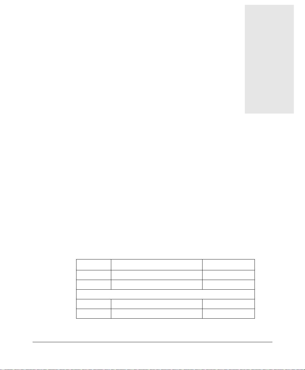
Setting the data transmission rate
To set the DSLPipe DSU data transmission rate, use a pen to move the DIP
switches.Table 2-1 shows the DIP switch settings for each rate. Move the DIP
switch down to turn the switch on. Move a switch up to turn it off.
Table 2-1. Data tran smission settings
Rate DIP Switch 1 DIP Switch 2 DIP Switch 3
144 Kbps ON ON ON
272 Kbps ON ON OFF
400 Kbps ON OFF ON
528 Kbps ON OFF OFF
784 Kbps OFF ON ON
1168 Kbps OFF ON OFF
1552 Kbps OFF OFF ON
Setting up the DSLPipe DSU
2320 Kbps OFF OFF OFF
Configuring the unit as either CPE or COE
If you want the DSLPipe DSU to function as a CPE, leave the fourth DIP switch
in the up (off) position. If you want the unit to function as a COE, move the
fourth DIP switch down.
Note: JP3 and JP4 must be installed for Dip Switch 4 to be functional.
DSLPipe DSU (SDSL) User’s Guide 2-3
Page 18

Connecting the cables
Table 2-2 shows the proper setting for each configuration.
Table 2-2. CPE vs. COE configuration
Configuration DIP Switch 4
CPE OFF
COE ON
Connecting the cables
To connect your DSLPipe DSU:
1 Use the V.35 to DB-25 cable to connect the V.35 device to the DSLPipe
DSU.
2 Use the WAN cable to connect the DSLPipe DSU to the SDSL line.
3 Use the power supply cable to connect the DSLPipe DSU to a power source.
Plugging the power supply automatically turns on the DSLPipe DSU.
Checking the activity of the LED lights
To verify that your DSLPipe DSU is connected properly, observe the activity
pattern of the lights at the front of the unit (see Figure ). When all the cables are
connected, verify that:
•The con light is on initially and then turns off. It blinks if there are any
SDSL errors.
•The wan light turns on after the con light turns off. It blinks until a
connection is established, and then remains on.
•The lnk light is on if the DSR (Data Set Ready) or the RTS (Request To
Send) control on the V.35 port is active.
•The act light blinks when there is any DSL activity, but it remains off
otherwise.
•The pwr light comes on and remains on.
2-4 DSLPipe DSU (SDSL) User’s Guide
Page 19

Figure 2-3 shows the location of the status lights on the DSLPipe DSU front
panel.
Figure 2-3. Location of the LED lights in the DSLPipe DSU front panel
DSLPipe DSU (SDSL) User’s Guide 2-5
Page 20

Page 21

Viewing configuration information
Items you need. . . . . . . . . . . . . . . . . . . . . . . . . . . . . . . . . . . . . . . . . . . . . . . . 3-1
Connecting serial cable and setting up communications software . . . . . . . . 3-1
Viewing configuration information . . . . . . . . . . . . . . . . . . . . . . . . . . . . . . . . 3-3
Viewing diagnostic information. . . . . . . . . . . . . . . . . . . . . . . . . . . . . . . . . . . 3-5
Before you can view the configuration information for the DSLPipe unit, you
must set up VT100 emulation to view the on-board software.
Items you need
• You need a serial cable that can plug into an available, enabled serial port on
your computer . The othe r end of t he cable must ha ve a male DB-9 connect or
to fit the serial port connector on the back of the DSLPipe unit. If your
computer is a Macintosh, the cable must fit the modem port’s nine-pin mini
DIN connector.
• You also need communications software that supports VT100 emulation.
3
Connecting serial cable and setting up communications software
To establish a serial connection, proceed as follows:
1 Use a serial cable to connect your computer’s serial (or modem) port to the
terminal port on the back of the DSLPipe unit.
DSLPipe DSU (SDSL) User’s Guide 3-1
Page 22

Connecting serial cable and setting up communications software
2 Use a communications program (such as HyperTerm, PROCOMM PLUS,
Zterm, or any other program that supports VT100 terminal emulation) to
open a session directly with the port to which the DSLPipe unit is connected.
3 Set your communications software to connect with the following settings:
Note: If you are not already familiar with the settings listed, see the
documentation for your communications software. If you’re using the
software for the first time, going through an online or printed tutorial (if the
software includes one) is a good way to get started.
– Direct connection: Tell the software that there is a serial cable
connecting the DSLPipe directly to the computer.
– Serial port: Specify which of the computer’s serial ports the software
uses. If the only serial port available is currently used by an internal
modem, you may need to use your computer’ s setup soft ware to specify
an external connector for the port that will be used in place of the
internal modem. In some cases, you also may need to remove the
modem. See the manual for the modem and your computer’s user
manual for details.
– Terminal type: Specify VT100.
– Duplex: If the software lets you choose, specify Full. Because this is by
far the most common choice, most communications software sets this
by default.
– Bits per second: Specify 57600.
– Data bits: Specify 8.
– Parity: Specify None.
– Stop bits: Specify 1.
– Flow control: Turn off software flow control (XON/XOFF) and, if
possible, hardware flow control (RTS/CTS). Specify None.
4 Your communications program should now display the DSLPipe main
window. If it does not, press the Enter key.
The following message appears on the screen:
Select Function Items?
Press Ctrl-L and the following message appears:
Press any key to continue...
3-2 DSLPipe DSU (SDSL) User’s Guide
Page 23

Viewing configuration information
Press any key on the keyboard and the DSLPipe unit’s configuration menu
appears:
SDSL V.35 DSU Software Version 3.31
0. Show DSL Status
1. Change Configuration
2. Upgrade Operation Software
3. Upgrade SDSL Firmware
4. Debug Mode
Figure 3-1. DSLPipe configuration window
Note: At this time, you cannot change DSLPipe configuration, upgrade the
DSLPipe software, or upgrade the DSLPipe firmware using the on-board
software. In other words, you cannot change anything by using options 1, 2, or
3 from the DSLPipe configurat ion window (see Figure 3-1).
Viewing configuration information
After you set up the communications software and the DSLPipe unit’s
configuration menu appears (see Figure 3-1), you can enter 0 to view DSLPipe
status information. The DSLPipe status screen continues to refresh every few
seconds -- press any key to stop the refresh. Table 3-1 describes the fields that
display in the status window.
Table 3-1. Fields in the DSLPipe status window
Fields Description
Bitpump Status Shows either OK or NG (No Good).
Terminal Type Indicates CO (Central Office) or RT (Remote Terminal) mode.
Operation Status Indicates UP or DN.
DSLPipe DSU (SDSL) User’s Guide 3-3
Page 24

Viewing configuration info rmati on
Table 3-1. Fields in the DSLPipe status window (Continued)
Fields Description
V35 Indicates OFF_line or ON_line
Data Bit Polarity Indicates Norm (Normal) or Rev (Reverse). The default is
Rev.This means that the transmitter inverts the data polarity
before sending data.
Sign/Magn Bit Seq Indicates Norm (Normal) or Rev (Reverse). The default is
Rev. This means that the magnitude bit is followed by the sign
bit.
Noise Margin Shows the noise margin value (in dB). If the noise margin is
less than -5dB, the SDSL line is terminated.
Data Rate Shows the current transmission rate
DSL ch Data
Encode/Decode
V.35 ch Data
Encode/Decode
DSL ch Rx CRC Shows either Enable or Disable. The default is Enable.
DSL ch Tx CRC Shows either Enable or Disable. The default is Enable.
V.35 ch Rx CRC Shows either Enable or Disable. The default is Enable.
3-4 DSLPipe DSU (SDSL) User’s Guide
Shows one of the following: NRZ, NRZI, FMO, FM1, or
Manchester. The default is NRZ. This means that signal
transmissions go from positive to n e gative without ever
assuming a zero value (Non-Return to Zero).
Shows one of the following: NRZ, NRZI, FMO, FM1, or
Manchester. The default is NRZ. This means that signal
transmissions go from positive to n e gative without ever
assuming a zero value (Non-Return to Zero).
This means that the receiver will check for CRC over the SDSL
line.
This means that the CRC is appended to the end of the frame
when data is sent over the SDSL line.
This means that the receiver will check for CRC over the V.35
line.
Page 25

Viewing diagnostic information
Table 3-1. Fields in the DSLPipe status window (Continued)
Fields Description
V.35 ch Tx CRC Shows either Enable or Disable. The default is Enable.
This means that the CRC is appended to the end of the frame
when data is sent over the V.35 line.
V.35 ch RxC
Polarity
V.35 ch TxC
Polarity
Indicates Norm (Normal) or Rev (Reverse). The default is
Norm.This means that data will be sampled at the rising edge
of the clock.
Indicates Norm (Normal) or Rev (Reverse). The default is
Norm.This means that data will be shifted out of the buffer at
the falling edge of the clock.
Viewing diagnostic information
After you set up the communications software and the DSLPipe unit’s
configuration menu appears (see Figure 3-1), you can press 4 to enter debug
mode and view diagnostic information. When you press 4, the following window
appears:
SDSL V.35 DSU Debug Mode
0. Return to Main Menu
1. Check HDLC Registers
2. Print Rx Data
Figure 3-2. Debug Mode window
At the Select Function Items prompt, press 1 to display the HDLC
registers. Table 3-2 describ e s the fields that display in the list that appears.
DSLPipe DSU (SDSL) User’s Guide 3-5
Page 26

Viewing diagnostic inf ormation
Table 3-2. Fields in the HDLC Registers list
Fields Description
HDMARXCNTA
HDMARXCNTB
HINTENA
HINTENB
HSTATA
HSTATB
HCON0A
HCON0B
HCON1A
These fields are not currently supported.
HCON1B
SDSL_RX PACKETS Shows the number of packets received by the SDSL line.
V35_RX PACKETS Shows the number of packets received by the V.35 line.
V35_RX_ERROR_COUNT Shows the number of errors received by the V.35 receiver.
V35_TX_ERROR_COUNT Shows the number of errors transmitted by the V.35 transmitter.
SDSL_RX_ERROR_COUNT Shows the number of errors received by the SDSL receiver.
SDSL_TX_ERROR_COUNT Shows the number of errors transmitted by the SDSL transmitter.
DMA_TXA_STATUS Shows Working if the SDSL line is working. Oth erwise, shows
Non-Working.
3-6 DSLPipe DSU (SDSL) User’s Guide
Page 27

Viewing diagnostic information
Table 3-2. Fields in the HDLC Registers list (Continued)
Fields Description
DMA_TXB_STATUS Shows Working if the V.35 line is wo rking. Otherwise, shows
Non-Working.
DSLPipe DSU (SDSL) User’s Guide 3-7
Page 28

Page 29

Hardware Specifications
Table A-1 lists the DSLPipe DSU specifications.
Table A-1. DSLPipe DSU specifications
Physical connectors RJ-11 for SDSL WAN
DB-25 to V.35 connector
Transmission rate 144 Kbps - 2320 Kbps
DSL line code 2B1Q
Line impedance 135 ohms
Dimensions 220mm x 169mm x 40mm
Weight Approximately 2 lbs (0.9 kg)
Electrical, power input 1A @ 9 to 18 VDC via AC Adapter
Electrical, power consumption Less than 5 watts
Operating hu midity 5% - 95%, noncondensing
A
Operating temperature 0-50° C
EMC FCC-15B
Safety UL
DSLPipe DSU (SDSL) User’s Guide A-1
Page 30

Page 31

Warranties and FCC Regulations
Product warranty . . . . . . . . . . . . . . . . . . . . . . . . . . . . . . . . . . . . . . . . . . . . . . B -1
FCC Part 15 Notice . . . . . . . . . . . . . . . . . . . . . . . . . . . . . . . . . . . . . . . . . . . . B-2
IC CS-03 Notice . . . . . . . . . . . . . . . . . . . . . . . . . . . . . . . . . . . . . . . . . . . . . . B-3
Product warranty
1 Lucent Technologies warrants that the DSLPipe V.35 unit will be free from
defects in material and workmanship f or a period of twelve (12) months from
date of shipment.
2 Lucent Technologies shall incur no liability under this warranty if:
– The allegedly defective goods are not returned prepaid to Lucent
Technologies within thirty (30) days of the discovery of the alleged defect
and in accordance with Lucent Technologies’ repair procedures; or
– Lucent Technologies’ tests disclose that the alleged defect is not due to
defects in material or workmanship.
3 Lucent Technologies’ liability shall be limited to either repair or replacement of
the defective goods, at Lucent Technologies’ option.
4 Lucent Technologies MAKES NO EXPR ESS OR IMPLIED WARRANTIES
REGARDING THE QUALITY, MERCHANTABILITY, OR FITNESS FOR A
PARTICULAR PURPOSE BEYOND THOSE THAT APPEAR IN THE
APPLICABLE Lucent Technologies USER'S DOCUMENTATION. Lucent
Technologies SHALL NOT BE RESPONSIBLE FOR CONSEQUENTIAL,
INCIDENT AL, OR PUNITIVE DAMAGE, INCLUDING, BUT NOT LIMITED
TO, LOSS OF PROFITS OR DAMAGES TO BUSINESS OR BUSINESS
B
DSLPipe DSU (SDSL) User’s Guide B-1
Page 32

Warranties and FCC Regulations
FCC Part 15 Notice
RELATIONS. THIS WARRANTY IS IN LIEU OF ALL OTHER
WARRANTIES.
Warranty repair
1 During the first three (3) months of ownership, Lucent Technologies will repair
or replace a defective product covered under warranty within twenty-four (24)
hours of receipt of the product. During the fourth (4th) through twelfth (12th)
months of ownership, Lucent Technologies will repair or replace a defective
product covered under warranty within ten (10) days of receipt of the product.
The warranty period for the replaced product shall be ninety (90) days or the
remainder of the warranty period of the original unit, whichever is greater.
Lucent Technologies will ship surface freight. Expedited freight is at customer’s
expense.
2 The customer must return the defective product to Lucent Technologies within
fourteen (14) days after the request for replacement. If the defective product is
not returned within this time period, Lucent Technologies will bill the customer
for the product at list price.
Out-of warranty repair
Lucent T echnologies will either repair or , at its option, replace a defective product not
covered under warranty within ten (10) workin g days of its receipt. R epair char ges are
available from the Repair Facility upon r equest. The warranty on a serviced product is
thirty (30) days measured from date of service. Out-of-warranty repair charges are
based upon the prices in effect at the time of return.
FCC Part 15 Notice
!
B-2 DSLPipe DSU (SDSL) User’s Guide
Warning: This equipment has been tested and found to comply with the limits
for a Class B digital device, pursuant to Part 15 of the FCC rules. These limits are
designed to provide reasonable protection against harm ful interference when the
equipment is operated in a residential environment. This equipment generates,
uses, and can radiate radio frequency energy, and, if not installed and used in
accordance with the instruction manual, may cause harmful interference to radio
communications. Operation of this equipment in a residential area is unlikely to
Page 33

cause harmful interference. But if it does, the user will be required to correct the
interference at his or her own expense.
The authority to operate this equipment is conditioned by the requirement that no
modifications will be made to the equipment unless the changes or modifications are
expressly approved by Lucent Technologies.
IC CS-03 Notice
The Industry Canada label identifies certified equipment. This certification means
that the equipment meets certain telecommunications network protective, operational,
and safety requirements as prescribed in the appropriate Terminal Equipment
Technical Requirements document(s). The Department does not guarantee that the
equipment will operate to the user’s satisfaction.
Before installing this equipment, users should make sure that it is permissible to b e
connected to the facilities of the local telecommunications company. An acceptable
method of connection must be used to install the equipment. The customer should be
aware that compliance with the above conditions may not prevent degradation of
service in some situations.
Warranties and FCC Regulations
IC CS-03 Notice
Repairs to certified equipment should be coordinated by a representative designated
by the supplier. Any repairs or alterations made by the user to this equipm ent, or
equipment malfunctions, ma y giv e the teleco mmunica tions company cause to r equest
the user to disconnect the equipment.
Users should ensure for their own protection that th e electrical gr oun d conn ections of
the power utility, telephone lines, and internal metallic water pipe system, if present,
are connected together. This precaution may be particularly important in rural areas.
Warning: Users should not attempt to make such connections themselves, but should
contact the appropriate electric inspection authority, or electrician, as appropriate.
DSLPipe DSU (SDSL) User’s Guide B-3
Page 34

 Loading...