

Page 1

Remote Port Security Device
User’s Guide
555-024-402
Comcode 107748717
Issue 1
October 1996
Page 2

Copyright 1996, L ucent Technologies Lucent Technol ogies 555-024-402
All Rights Reserved Issue 1
Printed in U.S.A. October 1996
Notice
Every effort was made to ensure that the information in this book was complete and accurate at the time of printing.
However, information is subject to change.
Your Responsibility for Your System’s Sec u rity
Toll fraud is the unauthor ized use of your telec ommunications system by an unauthor ized party, for example, persons
other than your company’s employees , agents, subcontract ors, or persons worki ng on your company’s beh alf. Note
that there may be a risk of toll fr aud associated with your telecommunications system, and if toll fraud occur s, it can
result in subst antial additional charges for your telecommunications services.
You and your sys tem ma nager ar e respo nsi ble f or th e se curit y of y our sy ste m, s uch as pr ogram ming and conf iguri ng
your equipment to prevent unauthorized use. The system manager is also responsible for reading all installation, instruction, and system administration documents provided with this product in order to fully understand the features
that can introduc e risk of toll frau d and the steps t hat can be take n to reduce th at ris k. Lucent Technologi es does not
warrant that this product is immune from or will prevent unauthorized use of common-carrier telecommuni cation services or facilities accessed through or connected to it. Lucent Technologies will not be responsible for any charges
that result from such unauthorized use.
Federal Communication Commission (FCC) Statement
This equipment has been tested and found to comply wit h the limits for a Class A digital device, pursuant to Par t 15
of the FCC Rules. These limits are designed to provide reasonabl e protection against harmful interf erence when the
equipment is opera ted in a commer cial environ ment. This equ ipment gene rates, uses , and can radiate r adio freque ncy energy and, if not installed and used in accordance with the instruction manual, may cause harmful interference
to radio communications. However, there is no guarantee that interference will not occur in a particular installation.
For further FCC informat ion, see “Customer Support Information” below.
Trademarks
DEFINITY, UNIX, AUDIX, DIMENSION, M ERLIN, and PA RTNER are register ed trademarks of Lucent Technologies in
the US and other countries.
Ord e ri n g In form at io n
Call:Lucent Technologies Fulfillment Center
Voice 1 800 457-1235International Voice 317 361-5353
Fax 1 800 457-1764International Fax 317 361-5355
Write:Lucent Technologies Fulfillment Center
P.O. Box 4100
Crawfordsvil le, IN 47933
Order:Document No. Lucent Technologies 555-024-402
Comcode 10774877
Issue 2, July 1996
For more information about Lucent Technologies documents, refer to the section entitled “Related Documents” in
“About This Book.”
Support Telephon e Number
In the continental US, Lucent Technologies provides a toll-free customer helpline 24 hours a day. Call the Lucent
Technologie s Helpline at 1 800 242-2121 or your Lu cent Technolo gies author ized dealer i f you need ass istance when
installing, programming, or using your system. Outside the continental US, contact your local Lucent Technologies
representative.
Lucent Technologies Fraud Interventi o n
If you
suspect you ar e being victimi zed
nical Service Cent er at 1 800 643-2353 or 1 800 242-2121.
Warranty
Lucent Technologies provides a limited warranty on this product. Refer to “Limited Warranty” in “Customer Support
Information.”
by toll fr aud and you need techn ical support or assist ance, call the BCS Tec h-
Page 3

Remote Port Security Device
User’s Guide
555-024-402
Contents
Contents
Contents iii
Customer Support Information xi
■ Support Telephone Number xi
■ Security of Your System: Preventing Toll Fraud xii
■ Lucent Technologies Fraud Intervention xiii
■ Guarantee xiii
RPSD Lock with no Keys xiii
RPSD Lock with Keys xiv
■ Limited Warranty xv
■ FCC Notification and Repair Information xvi
Issue 1
October 1996
Page iii
■ Installation and Operational Procedures xvii
■ Federal Communication Commission
(FCC) Electromagnetic Interference
Information xviii
About This Book xix
■ Intended Audiences xix
■ Responsibilities xix
■ Terms and Conventions xx
■ Typographical Conventions xxi
■ How to Use This Book xxi
■ Product Safety Labels xxii
■ Related Documents xxii
■ How to Comment on This Document xxii
1 Introduction 1-1
■ RPSD System 1-2
■ Hardware Components 1-5
RPSD Lock 1-5
RPSD Key 1-7
Modems 1-8
RPSD Lock or Key Administration Terminal 1-9
RPSD Lock Administration Pr inter 1-9
■ Software Components 1-10
■ System Administration 1-11
Time of Day Access 1-11
Page 4

Remote Port Security Device
User’s Guide
Contents
555-024-402
System Activity Log 1-12
Single Point Administration 1-14
Block Lucent Technologies and Other Key Users 1-15
Force Connect/Disconnect 1-15
Authorized Keys 1-16
2 Installation 2-1
■ Room Layout/Environment 2-2
Power Supply 2-2
Location of Administration Terminal or Printer 2-3
■ Installation 2-4
Cables, Connectors, and Ports 2-5
Issue 1
October 1996
Page iv
Insta lling the RPSD L oc k 2-5
Insta lling the RPSD K e y 2-16
Testing an Uninitialized Key 2-18
Initializing the RPSD Lock 2-18
Initializing the RPSD Key 2-19
■ Testing the RPSD Lock Installation 2-20
3 RPSD System Admini s t rat ion 3-1
■ Menu of Commands 3-2
■ Command Functions 3-5
A—Add User 3-6
AH—Access History 3-11
AA—Administra ti ve Acce ss His to ry 3-14
AF—A dministra ti ve Fa ilur e H is t o ry 3-17
AS—AUX Security 3-19
B—Block User 3-21
CR—Change Restriction 3-22
C—Clock Set 3-24
D—Date Set 3-25
FH—Failure History 3-26
FC—Force Connect 3-29
FD—Force Disconnect 3-30
I—ID Set 3-31
LR—List Restrictions 3-32
LS—List Statistics 3-34
Page 5

Remote Port Security Device
User’s Guide
Contents
555-024-402
L—List User Table 3-36
LH—Log History 3-40
Q—Quit 3-44
R—Remove User 3-45
RS—Reset Statistics 3-46
SC—Set Communicat ions Parameters 3-47
ST— Statu s Displa y 3-48
T—Test User 3-50
U—Unblock User 3-51
UR—User Restrictions 3-52
Help Screens 3-54
Issue 1
October 1996
Page v
4 Key Administration and Use 4-1
■ RPSD Key User Command Set 4-2
■ Initialization Functions 4-3
U—Set User ID 4-3
K—Set Secret Key 4-4
N—Set Device Number 4-5
■ Command Functions 4-6
A—Add Administrative User 4-7
AS—AUX Security 4-9
C—Clock Set 4-10
D—Date Set 4-11
H—History Display 4-12
I—Set Log ID 4-14
L—List User Information 4-15
LA—List Administrative Users 4-16
Q—Quit 4-17
R—Remove Administrative User 4-18
S—Status Display 4-19
SC—Set Communicat ions Parameters 4-20
W—Wipe Out 4-21
?—Help 4-22
■ Authentication 4-23
Password Authentication 4-23
PassKey Authentication 4-24
Page 6

Remote Port Security Device
User’s Guide
555-024-402
Contents
5 Troubleshooting 5-1
■ Access Failure Messages. 5-2
■ Testing the RPSD Lock 5-6
Built-in Diagnostics 5-6
Hardware Replacement 5-9
■ Replacing the RPSD Lock or Key 5-10
■ Saving the Key Seed Value 5-11
A Cabl es, Conn ector s , and Ports A-1
B Front Pa nel LEDs B-1
■ RPSD Lock B-2
■ RPSD Key B-3
Issue 1
October 1996
Page vi
Page 7

Remote Port Security Device
User’s Guide
555-024-402
October 1996
The exclamation point in an equilateral triangle is
intended to alert the user to the presence of important
operating and maintenance (servicing) instructions in
the literature accompanying the product.
When installing telephone equipment, always follow basic safety precautions to reduce
the risk of fire, electrical shock, and injury to persons, including:
■ Read and understand all instructions.
■ Follow all warnings and instructions marked on or packed with the
product.
■ Never install this unit or telephone wiring for it during a lightning storm.
Issue 1
Page ix
■ Never install a telephone jack in a wet location unless the jack is
specifically designed for wet locations.
■ Never touch uninsulated telephone wires or terminals unless the
telephone wiring has been disconnected at the network interface.
■ Use caution when installing or modifying telephone lines.
■ Use only Lucent Technologies-manufactured circuit packs, carrier
assemblies, and power units in the control unit.
■ Use only Lucent Technologies-recommended/approved accesso ries.
■ Do not install this product near water, for example, in a wet basement
location.
■ Do not overload wall outlets, as this can result in the risk of fire or
electrical shock.
■ Do not attach the power supply cord to building surfaces. Do not allow
anything to rest on the power cord. Do not locate this product where the
cord will be abused by per s on s wa lk ing on it.
■ Unplug the product from the wall outlet b efore cleaning. Use a damp cloth
for cleaning. Do not use cleaners or aerosol cleaners.
■ Do not operate the system if chemical gas leakage is suspected in the
area. Use telephones located in some other safe area to rep ort the trouble.
!
WARNING:
DO NOT open the RPSD Lock or Key devices. There are no user
serviceable parts inside the units. Only an authorized technician should
open a unit for required maintenance or upgrading purpo ses.
SAVE THESE INSTRUCTIONS
Page 8

Remote Port Security Device
User’s Guide
555-024-402
Issue 1
October 1996
Page x
Page 9

Remote Port Security Device
User’s Guide
Customer Suppor t Information
555-024-402
Customer Support Information
Support Telephone Number
In the USA only, Lucent Technologies provides a toll-tree customer Helpline,
1 800 242-2121, 24 hours a day. If you need assistance when ins t allin g,
programming, or using your system, call the Helpline, or your Lucent
Technologies authorized representative.
Issue 1
October 1996
Page xiSupport Telephone Number
Outside the USA, if you need assistance when installing, programming, or using
your system, contact your Lucent Technologies authorized representative.
Page 10

Remote Port Security Device
User’s Guide
Customer Suppor t Information
555-024-402
Security of Your System: Preventing
Toll Fraud
As a customer of a new communications device, you should be aware that there
is an increasing problem of telephone toll fraud. Telephone toll fraud can occur in
many forms, despite the numerous efforts of telephone companies and
telephone equipment manufacturers to control it. Some individuals use electronic
devices to prevent or falsify records of these calls. Others charge calls to
someone else’s number by illegall y usin g los t or stolen calling cards, billing
innocent parties, clipping on to some one else’s line, or breaking into someone
else’s telephone equipment phys ically or electronically. In certain instances,
unauthorized individuals make connections to the telephone network through the
use of remote access features.
Common carriers are required by law to collect their tariffed charges. While these
charges are fraudulent charges made by persons with criminal intent, applicable
tariffs state that the customer of record is responsible for payment of all longdistance or other network charges. Lucent Technologies cannot be responsible
for such charges and will not make any allowance or give any credit for charges
that result from unauthorized access.
Issue 1
October 1996
Page xiiSecurit y of Your System: Preventi ng Toll Fraud
To minimize the risk of unauthorized access to your communications system or
device:
■ When possible, restrict the off-network capability of off- premises callers,
using calling restrictions, Facility Restriction Levels, and Disallowed List
capabilities.
■ When possible, block out-of-hours calling.
■ Frequently monitor system call detail reports for quicker detection of any
unauthorized or abnorma l calling patterns .
■ Limit outcallin g to pe rson s on a need-to- have bas i s.
The communications system, through proper administration, can help you
reduce the risk of unauthorized persons gaining access to the network. However ,
phone numbers and authorization codes can be compromised when overheard
in a public location, lost through theft of a wallet or purse containing acc ess
information, or when treated carelessly (writing codes on a piece of paper and
improper ly discarding them).
Additionally, hackers may use a computer to dial an access code and then
publish the information to other hackers. Substanti al charges can accu mulate
quickly. It is your responsibility to take appropriate ste ps to im plement th e
features properly, to evaluate and administer the various restriction levels, and to
protect and carefully distribute access codes.
Under applicable tariffs, you will be responsible for payment of toll charges.
Lucent Technologies cannot be responsible for such charges and will not make
any allowance or give any credit resulting from unauthorized access.
Page 11

Remote Port Security Device
User’s Guide
Customer Suppor t Information
555-024-402
Lucent Technologies Fraud
Intervention
If you suspect you are being victimized by toll fraud and you need technical
support or assistance, call the following:
■ For DEFINITY and Voice Mail products, call the Technical Service Center
(TSC) at 1 800 242-2121.
■ For system 25, MERLIN, and PARTNER products, call t he National S ervice
Assistance Center (NSAC) at 1 800 628-2888.
Guarantee
Lucent Technologies sells the Remote Port Security Device (RPSD) to provide an
additional layer of security for the remote administration port on Lucent
Technologies communications systems and other Lucent Technologies BCS
products. Lucent Technologies offers the following guarantee for the RPSD on
Lucent Technologies communications systems located within the United States.
Issue 1
October 1996
Page xiiiLucent Technologies Fraud Int ervention
RPSD Lock with no Keys
If the customer purchases an RPSD Lock with no Keys, Lucent Technologies will
pay for unauthorized calls that occur as a result of access to the system via the
remote administration port through the RPSD, provided the following conditions
are met:
■ The RPSD was installed correctly on the remote administration port on the
Lucent Technologies communications system and conf igured at the time
of the fraud incident to accept only Lucent Technologies Keys.
NOTE:
In this context, correct installation means that the RPSD Lock is
installed consistent with installation instructions and in such a way as
to deny access in case of power failure.
■ The customer provides RPSD documentat ion to Lucent Technologies
showing the time of access.
■ The customer pr ovi des th e communi cations system h istory l og informati on
to Lucent Technologies showing the changes made to the system to allow
toll fraud at the time shown by the RPSD log.
■ The customer provides telephone records to Lucent Tech nolog ies that
indicate the fraud was accomplished via the change s made at that time.
■ The customer provides Lucent Technologies with access to all additional
information requested by Lucent Technologies regarding the fraud
incident.
Page 12
Remote Port Security Device
User’s Guide
Customer Suppor t Information
555-024-402
RPSD Lock with Keys
If the customer purchases RPSD Keys to access the systems protected by RPSD
Locks, Lucent Technologies does not assume responsibility for the use of
customer-purchased Keys. Accordingly, Lucent Technologies will pay for the
unauthorized calls that occur as a result of access to such systems via the
remote administration port through the RPSD provided the following conditions
are met:
■ The RPSD Lock was installed correctly on the remote administration port
on the DEFINITY system at the time of the fraud incident.
NOTE:
In this context, correct installation means that the RPSD Lock is
installed consistent with installation instructions and in such a way as
to deny access in case of power failure.
Issue 1
October 1996
Page xivGuarantee
■ The customer provides RPSD documentat ion to Lucent Technologies
showing the time of access and
Lucent Technologies ID
■ The customer pr ovi des th e communi cations system h istory l og informati on
.
that the access was accomplished via a
to Lucent Technologies showing the changes made to the system to allow
toll fraud at the time shown by the RPSD log.
■ The customer provides telephone records to Lucent Tech nolog ies that
indicate the fraud was accomplished via the change s made at that time.
■ The customer provides Lucent Technologies with access to all additional
information requested by Lucent Technologies regarding the fraud
incident.
Page 13

Remote Port Security Device
User’s Guide
Customer Suppor t Information
555-024-402
Whether or not the customer uses Keys, the customer agrees to promptly take all
necessary steps to stop the toll fraud after becoming aware of it. Lucent
Technologies’ liability under this RPSD guarantee ceases two hours after the
customer becomes aware of the toll fraud incident. In no event shall Lucent
Technologies’ responsibility exceed the amount of the customer’s payment to the
network provider for the unauthorized calls. Lucent T echnologies’ liability is
limited to the unauthorized calls and does not include consequential d ama ges
such as lost profits due to phone lines being unavailable.
Limited Warranty
Lucent Technologies, Inc. warrants this equipment to be free of defects in
materials and workmanship for a period of one year from date of shipment. All
defects within this time will be repaired without charge upon return of the unit to
the factory.
Issue 1
October 1996
Page xvLimited Warranty
This warranty is null and void if the manufacturer determines that any
modifications have been made to the unit or the unit has been subjected to
physical or electrical stress.
This warranty covers parts and labor only and does not include shipping costs,
travel expenses, or travel time.
Installation of the equipm ent is the sole responsib ilit y of the purchaser. The
manufacturer, its agents, or its distributors accept no responsibility for
malfunction or damage caused by improper treatment or connection of the unit.
The manufacturer, its agents, or its distributors are not liable for any losses
incurred through use or malfunction of the equipment or any losses or damages
incurred by the use of the equipment in any means whatsoever.
This warranty is limited to the repair of the equipment to its normal functioning
capability .
This warranty is complete as stated and all other warranties, expressed or
implied, are invalid. The Remote Port Security Device should be installed only by
qualified personnel. No user-serviceable parts are contained within the units.
Installation or programming should not begin prior to review of all sections of this
manual.
Page 14

Remote Port Security Device
User’s Guide
Customer Suppor t Information
555-024-402
FCC Notification and Repair
Information
This equipment is registered with the FCC in accordance with Part 68 of its rules.
In compliance with those rules, you are advised of the following:
■ Means of Connection. Connection of this equipment to the telephone
network shall be through a standard network interface jack, USOC RJ11C.
These USOCs must be ordered from your telephone company.
■ Party Lines and Coin Telephones. This equipment can not be used with
party lines or coin telephone lines.
■ Notification to the Tel epho ne Comp anie s. Before connecting this
equipment, you or your equipment supplier must notify your local
telephone company’s business office of the following:
Issue 1
October 1996
Page xviFCC Notification and Repair Inform ati on
— The telephone number(s) you will be using with this equipment.
— The appropriate registration number and ringer equivalence
number (REN), which can be found on the back or bottom of the
control unit.
— For each jack, the sequence in which lines are to be connected, the
line types, the Facility Interface Code (FIC), and the Ringer
Equivalence Number (REN) by position when applicable.
■ Ringer Equivalence Number (REN). The REN is used to determine the
number of devices that can be connected to the telephone line. Excessive
RENs on the line can result in the devices not ringing in response to an
incoming call. In most, but not all, areas the sum of the RENs should not
exceed five (5.0). To be cert ain of the number of devices that can be
connected to the line, as determined by the total RENs, contact the local
telephone company to determine the maximum REN for the calling area.
■ Disconnection. You must also notify your local telephone company if and
when this equipment is permanent ly discon nect ed from the line(s).
Page 15

Remote Port Security Device
User’s Guide
Customer Suppor t Information
555-024-402
Installatio n a nd Operational
Procedures
This manual contains information ab out installation and opera tional procedures.
■ Repair Instructions. If you experience trouble because your equipment is
malfunctioning, the FCC requires that the equipment not be used and that
it be disconnected from the network until the problem has been corrected.
Repairs to this equipment can be made only by the manufacturers, their
authorized agents, or others who may be authorized by the FCC. In the
event repairs are needed on this equipment, contact your authorized
Lucent Technologies dealer or, in the USA only, contact the National
Service Assistance Center (NSAC) at 1 800 242-2121.
■ Rights of the Local Telephone Company. If this equipment causes harm to
the telephone network, the local telephone company may discontinue your
service temporarily . If possible, they will notify you in advance. But if
advance notice is not practical, you will be notified as soon as poss ibl e.
You will also be in f ormed of y our ri ght to fi le a co mplaint wit h the FC C .
Issue 1
October 1996
Page xviiInstallation and Operational Procedures
■ Changes at Local Telephone Company. Your local telephone company
may make changes in its facilities, equipment, operations, or procedures
that affect the proper functioning of this equipment. If they do, you will be
notified in advance to give you an opportunity to maintain uninterrupted
telephone service.
■ New Network Area and Exchange Codes. The communications system
software does not restrict access to any new area codes or exchange
codes established by a local telephone comp any. If the user has
established toll restrictions on the system that could restrict access, then
the user should check the lists of allowed and disallowed dial codes and
modify them as needed.
■ Equal Access Codes. This equipment is capable of providing users
access to interstate providers of operator services through the use of
access codes. Modifications of this equipment by call aggregators to
block access dialing codes is a violation of the Telephone Operator
Consumers Act of 1990.
Page 16

Remote Port Security Device
User’s Guide
Customer Suppor t Information
555-024-402
Federal Communication Commission
(FCC) Electromagn eti c Inter feren ce
Information
This equipment has been tested and found to comply with the limits for a Class A
digital device, pursuant to Part 15 of the FCC Rules. These limits are designed to
provide reasonable protection against harmful interference when the equipmen t
is operated in a commercial environment. This equipment generates, uses, and
can radiate radio frequency energy and, if not installed and used in accordance
with the instruction manual, may cause harmful interference to radio
communications .
Issue 1
October 1996
Page xviiiFederal Communication Co mmission (FCC) Electromagnetic Interference Information
Page 17

Remote Port Security Device
User’s Guide
About This Book
555-024-402
About This Book
Intended Audiences
This document is intended for the following audience:
Issue 1
October 1996
Page xixIntended Audiences
■ Lucent Technologies technicians
■ RPSD system administrato rs
■ RPSD Key users
Lucent Technologies technicians are the personnel from Lucent Tec hnolog ies
who install the Remote Port Security Device (RPSD) Lock at the customer
premises. It is assumed that Lucent Te chnolo gies te chnicians are familiar with
the technical language used to describe the hardware components, cables,
connectors, and ports involved in the installation of the RPSD Lock. It is further
assumed that they will have the tools and equipment necessary for installation.
RPSD system administrators are the customer personnel who administer and
maintain the RPSD Lock. It is assumed that RPSD system adm inistrators are
familiar with menu-driven telecommunications hardware components. It is also
assumed that they understand the need for maintaining security in administering
the communications system.
RPSD Key users are those who dial in to a channel locked with a Lock by using a
Key. It is assumed that Key users are familiar with placing calls via a modem,
either from a telephone, terminal, or PC.
Responsibilities
Lucent Technologies technicians are responsible for installing the RPSD Lock,
testing it upon installation, and making certain that a working product has been
installed. Lucent Technologies technicians also perform any replacement of the
Lock should it become necessary. Lucent T echnologies technicians are not
responsible for the initialization of the Lock. The Lock is initialized prior to
delivery, and the Key devices that are used by Lucent Technologies are already
installed and initia liz e d.
Page 18
Remote Port Security Device
User’s Guide
About This Book
555-024-402
RPSD Keys purchased by the customer can be installed by Lucent Technologies
technicians at the customer’s request or installed by the customers.
The troubleshooting material in this document may be used by the technician at
the time of installation, but it is written primarily for the customer. Failure of any
Lock or Key is always resolved by replacement of the failed device.
The Lock commands and administration material is written for RPSD system
administrators. The material on Key commands and use is written for Key users.
Supplying equipment peripheral to the Lock, such as term inals, mod em s,
printers , etc., is the cust omer’s respons ibility. If any mat e ria l is req uired in
addition t o the m a terial shipp ed in the RPSD pack age, it is billab le to the
customer.
Issue 1
October 1996
Page xxTerms and Conventions
Terms and Conven ti ons
The Remote Port Security Device (RPSD) Lock is often referred to as the Lock.
Similarly the RPSD Key is often referred to as the Key.
Throughout this document, toll fraud security hazards are indicated by an
exclamation point inside a triangle and the words Security Alert.
!
Security Alert:
Security Alert indicates the presence of a toll fraud security hazard. Toll
fraud is the unauthorized use of your telecommunications system by an
unauthorized party (for example, persons other than your company’s
employees, agents, subcontractors, or persons working on your company’s
behalf). Be sure to read “Your Responsibility for Your System’s Security” on
the inside front cover of this book and “Security of Your System: Preventing
Toll Fraud” in “About This Book.”
Page 19
Remote Port Security Device
User’s Guide
About This Book
555-024-402
Typogra phi c al Conventions
Throughout this manual RPSD system responses are shown in italic, sans serif
type. For example:
Call authentication completed
Data that you enter is shown in bold sans serif type. For example:
Issue 1
October 1996
Page xxiTypographi cal Conventions
Block user
ENTER
The button at the end of the line tells you to press the Enter or Return key
ENTER
to complete the command.
NOTE:
In this document, a remote caller’ s computer terminal or personal computer
is referred to as the user’s terminal. The local terminal conn ected to the
RPSD Lock is referred to as the system administrator’s terminal or
administration terminal.
How to Use This Book
This is organized into chapters that give information on procedures necessary for
the proper installation and administration of your Remote Port Security Device.
“Related Documents,” later in this section, provides a complete list of system
documentation, together with ordering information.
If you have problems with your RPSD system, contact your system administrator.
If the problem cannot be solved by the system administrator, in the continental
U.S. your system wi ll c a ll o u r to l l-free Helpline , ava i lab le 2 4 h ours a day, at 1 800
242-2121. Outside of the continental U.S., contact your Lucent Technologies
representative or local authorized dealer .
Page 20
Remote Port Security Device
User’s Guide
About This Book
555-024-402
Product Safety Labels
Throughout these documents, hazardous situations are indicated by an
exclamation point inside a triangle and the word
!
WARNING:
Warning indicates the presence of a hazard that could cause death or
severe personal injury if the hazard is not avoided.
!
CAUTION:
Caution indicates the presence of a hazard that could cause minor personal
injury or property damage if the hazard is not avoided.
caution
or
warning
Issue 1
October 1996
Page xxiiProdu ct Saf ety Labels
.
Related Documents
In addition to this book, the document listed below is part of the documentation
set. Within the continental United States, order this document from the BCS
Publications Fulf illm ent Cente r by call ing 1 800 457-1235.
Document No. Title
555-025-6000
GBCS Products Security Handbook
How to Comment on This Document
We welcome your comments, both positive and negative. Please use the
feedback form on the next page to let us know how we can continue to serve you.
If the feedback form is missing, write directly to:
Documentation Manag er
Lucent Technologies, Inc.
211 Mount Airy Road
Room 2W-226
Basking Ridge, NJ 07920-2332
Page 21
Remote Port Security Device
User’s Guide
555-024-402
About This Book
FEEDBACK FORM
Remote Port Security Device
Title: Remote Port Security Device User’s Guide
Order No.: 555-024-402 Date: October 1996
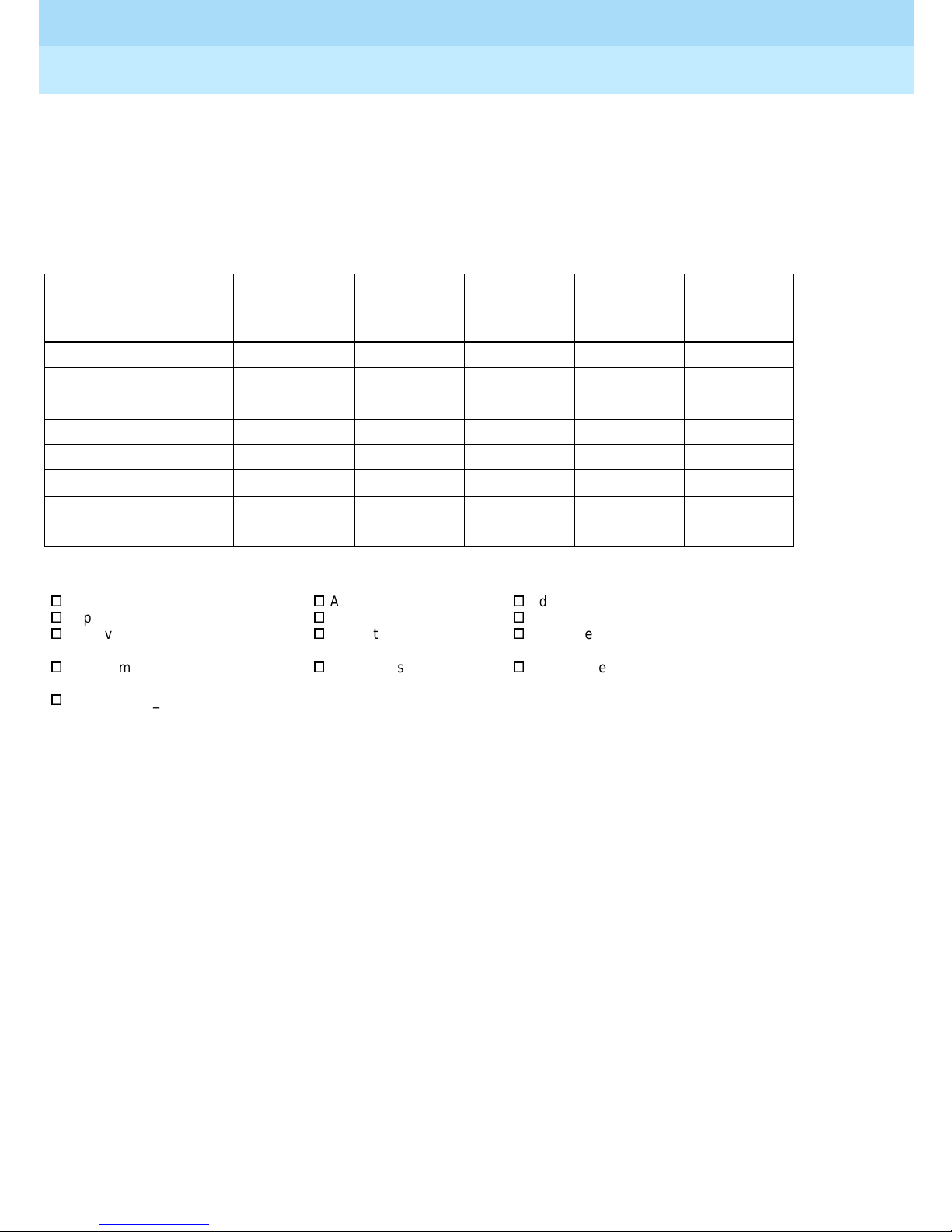
1. Please rate the effe ctiveness of this book in the following areas:
Excellent Good Fair Poor Not
Ease of Use
Clarity
Completeness
Accuracy
Organization
Appearance
Examples
Illustrations
Overall Satisfaction
Issue 1
October 1996
Page xxiiiHow to Comment on This Document
Applicable
2. Please check ways you feel we could improve this book:
o
Impro v e the overview
o
Improve the table of contents
o
Improve the organization
o
Include more illustrations
o
Other_______________ ___________________________ __________________________________ _________
_________________________ __________________________________________________________________
_________________________ __________________________________________________________________
3. What di d you like most about this book?
_________________________ _________________________________ _________________________________
_________________________ _________________________________ _________________________________
4. Feel f ree to write any comments below or on an attached sheet.
_________________________ _________________________________ _________________________________
_________________________ _________________________________ _________________________________
_________________________ _________________________________ _________________________________
_________________________ _________________________________ _________________________________
If we may contact you about yo ur comments, please complete the following:
Name: _________________________ _________________ ________Telephone Number: ___________ _______
Company/Organization: ____________ ___ _____________ ________Date: ________________ ______________
Address: ____________________________________________________________________________________
o
Add more examples
o
Add more detail
o
Make it more concise
o
Add more step-by-
step procedures
o
Add troubleshooting information
o
Make it less technical
o
Add more/better quick reference
aids
o
Impro v e the index/glos sary
Send completed forms to: Documentation Manager, Lucent Technologies, 211 Mount Airy Road, Room 2W226,
Basking Ridge, NJ 07920. Fax: ( 908) 953-6912.
THIS FORM MAY BE PHOTOCOPIED
Page 22

Remote Port Security Device
User’s Guide
555-024-402
About This Book
Issue 1
October 1996
Page xxivHow to Comment on This Document
Page 23

Remote Port Security Device
User’s Guide
Introduction
1
1
Introduction
555-024-402
Issue 1
October 1996
Page 1-1
1
The Remote Port Security Device (RPSD) is a single-line dial-up port protection
system that prevents unauthorized access to a host resource. Host resource
dial-up ports are protected by installing the RPSD Lock on the analog telephone
line leading to the port. Access is provided only when the calling party uses the
RPSD Key, a unit installed on the analog telephone line at the calling party end.
Page 24

Remote Port Security Device
User’s Guide
Introduction
1
555-024-402
RPSD Syst e m
The RPSD system provides security and control for virtually any type of dial-up
port on any host resource, regardless of the type of modem associated with the
host’ s dial-up ports. This document specifically targets Lucent T echnologies
Business Communications Systems customers and users of the communications
systems listed belo w and supporting periph er al pr o ducts; therefore, most
references in this document are specific to Business Communications Systems.
However, other applications of the RPSD system are possible.
Lucent Technologies supports RPSD use on the following types of
communications syst e ms:
■ System 75 (R1V2, R1V3)
■ System 85 (R1V1, R1V2, R2V1, R2V2, R2V3, R2V4)
Issue 1
October 1996
Page 1-2RPSD System
■ DEFINITY® Enterprise Communications Server (ECS) (all models)
■ DIMENSION
■ Other communications systems with dial-up ports
■ All voice-mail systems
■ Any product that supports analog tip-and-ring capability.
With the RPSD Lock and Key system you can set the time of day that access to a
port is permitted, or you can block any or all access to the line by users of RPSD
Keys. In addition, a system activity log provides a real-time record of access
attempts and their outcomes. Session sum maries track statistics on all
successful and failed attempts, providing convenient MIS data resources.
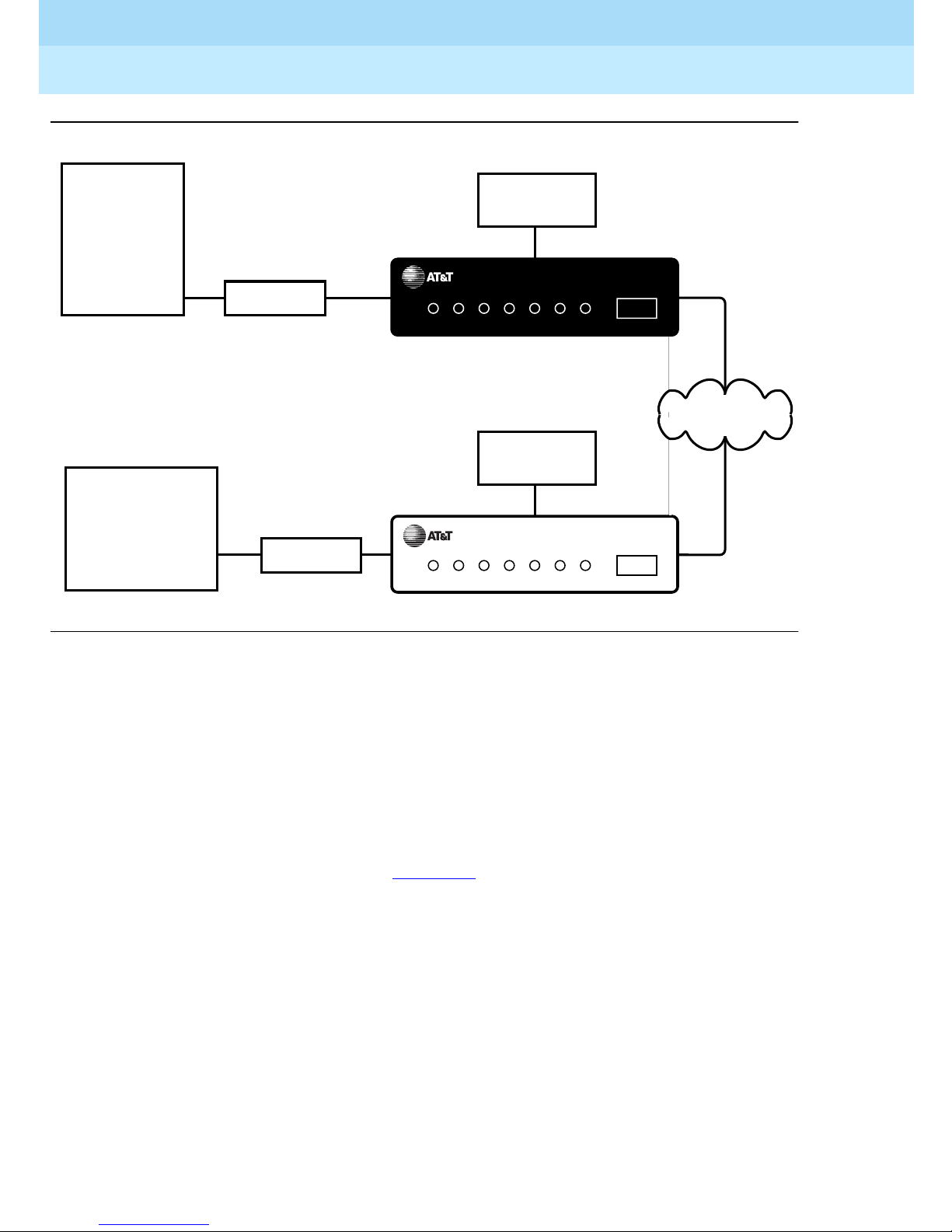
As shown in Fi gure 1-1
, the RPSD Lock is approximately the size of a modem
and is connected between the communi cations syst em modem and the cent ral
office line. The RPSD Key is of similar size and is connected between the caller’s
modem and central office line.
NOTE:
In Figure 1-1, the term “Lucent Technologies Remote Operations” refers to
Technical Services Center remote administration and maintenance
operations, Bell Labs Field Support, and other entities.
Page 25
Remote Port Security Device
User’s Guide
Introduction
1
Communications
System
Customer Remote
Administration
Terminals, Lucent
Technologies
Remote Operations,
System Management
Applications, etc.
555-024-402
Modem
Modem
POWER RINGINRING
POWER RING
OUT
IN
Administration
Terminal or
Printer
DEFINITY RPSD
CALL
LOCKED VERIFY CONNECTED
OUT
Administration
Terminal
DEFINITY RPSD
CALL
IDLE VERIFY CONNECTED
OUT
Issue 1
October 1996
Page 1-3RPSD System
LOCK
Public
Telephone
Network
KEY
Figure 1-1 . RPSD Loc k a nd Key Confi gu r at ion
The system administrator administers the RPSD Lock via a direct connection
from an administration terminal to the Lock. The administration interface is menu
driven.
The RPSD system protects a por t in the following manner: a call into the channel
to the protected host activates the RPSD Lock. Without involving the protected
host resource or its associated modem, the RPSD Lock verifies the caller’s
identity by using dual-tone, multifrequency (DTMF) signaling with the RPSD Key .
This process is as follows (see Figure 1-1
1. The Lock, installed on tip and ring on the network side of any modem or
protected host resource, answers the incoming call.
2. The Lock sends the caller a poll ing t one. If the callin g party has an RPSD
Key, the Ke y responds wit h its U ser ID. If there is no K ey on th e c alling
end, the Lock terminates the call.
3. The Lock must recognize the Key’s User ID (the Lock must be previously
initialized with all valid Keys); if not, the Lock terminates the call.
4. Using an algorithm governed by ANSI/DES standards, the Lock generates
a random 10-digit value (known as the “dynamic challenge,” for which
there are 10 billion possible values). Using a secret encryption key unique
to the calling RPSD Key’s User ID, the Lock encrypts the value.
).
Page 26

Remote Port Security Device
User’s Guide
Introduction
1
555-024-402
5. The Lock stores this encrypted “expected value” and sends the dynamic
challenge to the Key.
6. When the Key receives the challenge from the Lock, it uses the secret
encryption key unqiue to the user ID assigned to the Key and encrypts the
value the Lock sent. Following this, the Key calculates the necessary
response. The Key transmits this “expected value” to the Lock.
7. The Lock compares the Key’s response to the expected value it
calculated and stored. If the Lock receives the precise value it expects, it
generates ringing and sends the call on to the protected resource.
The entire sequence occurs in fewer than 20 seconds.
Issue 1
October 1996
Page 1-4RPSD System
Page 27

Remote Port Security Device
User’s Guide
Introduction
1
555-024-402
Hardwa re Compon e nts
To install a complete RPSD system, you need a Lock and a Key. A
communications system and modem are assumed to be at the customer site
already.
NOTE:
Although a printer is not essential to system operation, you should consider
dedicating a serial printer to the RPSD Lock. (The printer should be set to
9600 kbps, N, 8, 1.) The System Activity Log can store up to 1400
messages, but the only means of retaining a more permanent record of
system activi ty is eit her to i nstal l a dedic ated printer for the RPS D Lock or to
save all messages from the Lock to disk.
The Lucent Technologies personnel who require access to the communications
system already have the Keys they need. Any additional RPSD Keys f or customer
use mu st be orde red s eparately.
Issue 1
October 1996
Page 1-5Hardware Componen ts
The hardware components (both supplied and otherwise) and their requirements
are described in the following sections.
RPSD Lock
When you order the RPSD Lock, you receive:
If any other cables or connectors are required, they must be ordered separately.
In addition, any peripheral devices, such as the administration terminal or printer,
are customer supplied. Install the RPSD Lock between the maintenance and
administration channel and the commu nications s ystem modem.
■ The Lock
■ Power s upply
■ 7-foot line cord with RJ11 modular connectors on each end
■ 14-foot line cord with RJ11 modular connectors on each end
■ DB9 (male) to DB25 (female) cable
Page 28
Remote Port Security Device
User’s Guide
Introduction
1
555-024-402
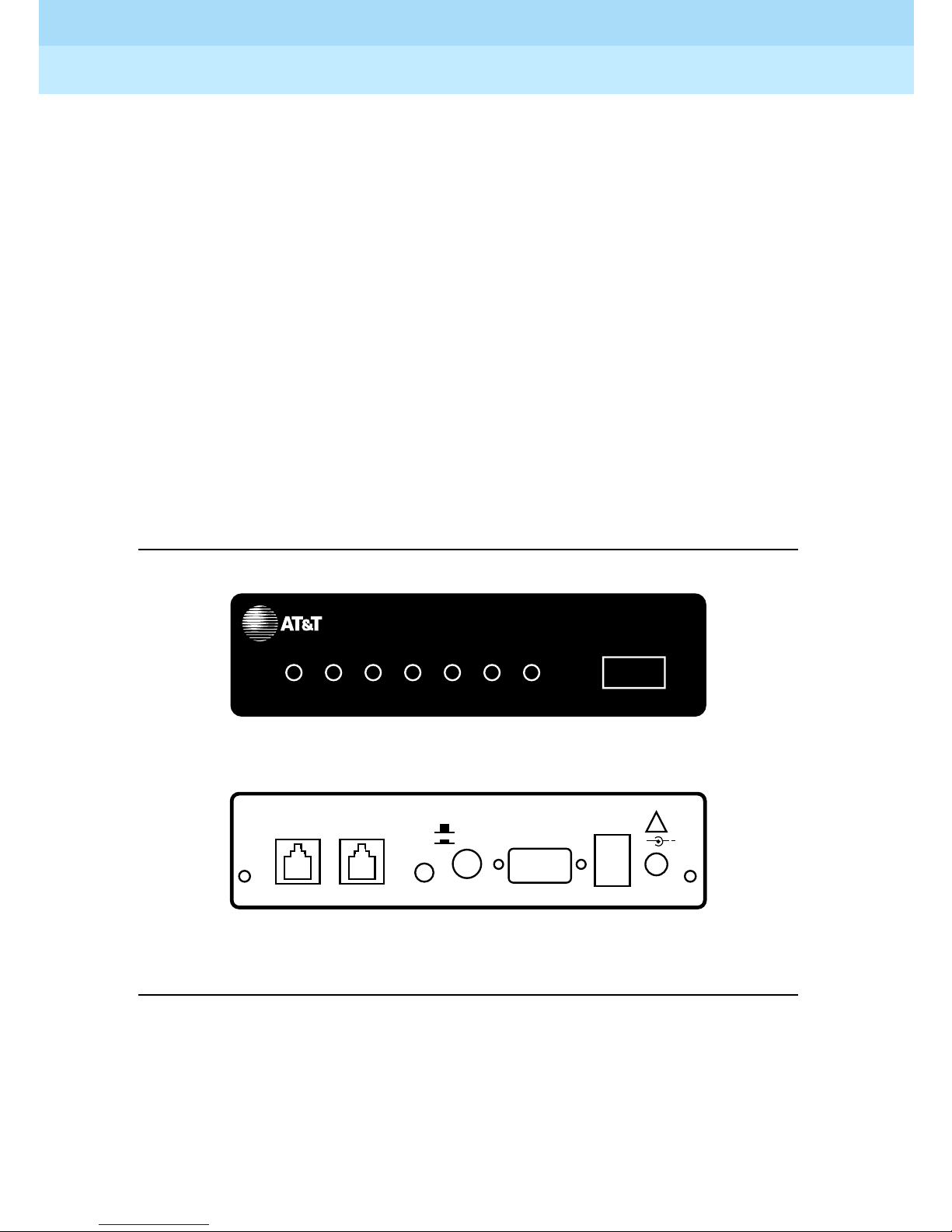
The RPSD Lock is 5.75 inches wide by 9.5 inches long by 1.75 inches high. It has
seven LEDs on the front panel and four ports on the back panel (see Figure 1-2).
For a detailed description of the front panel LEDs, see Appendix B, “Front Panel
LEDs.” The back panel ports are:
■ RJ11 port for the modem connection, labeled SUBSCRIBER
■ RJ11 port for the central office line, labeled TELCO
■ Female DB9 port for the terminal or printer (or a modem), labeled AUX.
PORT
■ Alarm leads to connect an external alarm
■ Port for the power supply (supplied with the RPSD Lock)
Issue 1
October 1996
Page 1-6Hardware Componen ts
POWER RINGINRING
SUBSCRIBER
(MODEM) TELCO
Figure 1-2. RPSD Lock
DEFINITY RPSD
CALL
OUT
LOCKED VERIFY CONNECTED
OUT
Front
RED
GREEN BYPASS
POWER MONITOR
SECURE
Back
AUX. PORT
LOCK
ALARM
LEADS
!
+
12VDC
1A
Power M on ito r Fu nctio n
The Power Monitor function allows you to control the behavior of the RPSD during
power failure conditions. The POWER MONITOR button on the back of the Lock
enables or disables this function.
Page 29

Remote Port Security Device
User’s Guide
Introduction
1
555-024-402
In the event of a unit failure or a power failure, the RPSD blocks incoming and
outgoing calls to the port, protecting the port against unauthorized access. This
call blocking also prevents the communications system or other protected
resources from originating an alarm and blocks dial-up access to the port.
However , you can push in the POWER MONITOR button on the back of the Lock
to enable the Power Monitor function. The green LED lights to indicate that the
Power Monitor function is enabled. When this function is enabled, the TELCO and
SUBSCRIBER ports are connected during a power failure, thereby bypassing the
Lock security. This bypassing permits incoming call s to the communication s
system or other host resource.
!
Security Alert:
When the POWER MONITOR button is IN during a unit or power failure, the
security of the RPSD Lock is bypassed. Leave the button in the OUT
position for security reasons.
Issue 1
October 1996
Page 1-7Hardware Componen ts
External Alarm
You can connect alarm leads to the screw terminals on the back of the Lock.
When a Lock failure occurs, contacts inside the Lock close and send a signal out
the alarm terminals to the communications system or other external alarm.
You can also use the Power Monitor function to generate a signal failure through
the alarm leads without bypassing the RPSD and compromising security. This is
called an
RPSD Key
The RPSD Key is similar to the RPSD Lock in size and appearance. When you
order the RPSD Key, you receive:
■ The Key
■ Power s upply
■ 7-foot line cord with RJ11 modular connectors on each end
■ 14-foot line cord with RJ11 modular connectors on each end
Alarm Only
installation.
■ DB9 (male) to DB25 (female) cable
Like the RPSD Lock, the RPSD Key has LEDs on the front panel and ports on the
back panel. For a detailed description of the front panel LEDs, see Appendix B,
“Front Panel LEDs.” The back panel ports are (see Figure 1-4):
■ RJ11 port for the central office line, labeled TELCO
■ RJ11 port for the modem connection, labeled SUBSCRIBER
■ Female DB9 port for the terminal or printer , labeled AUX. PORT
■ Port fo r the powe r supply (supplied with the RPSD Key) .
Page 30
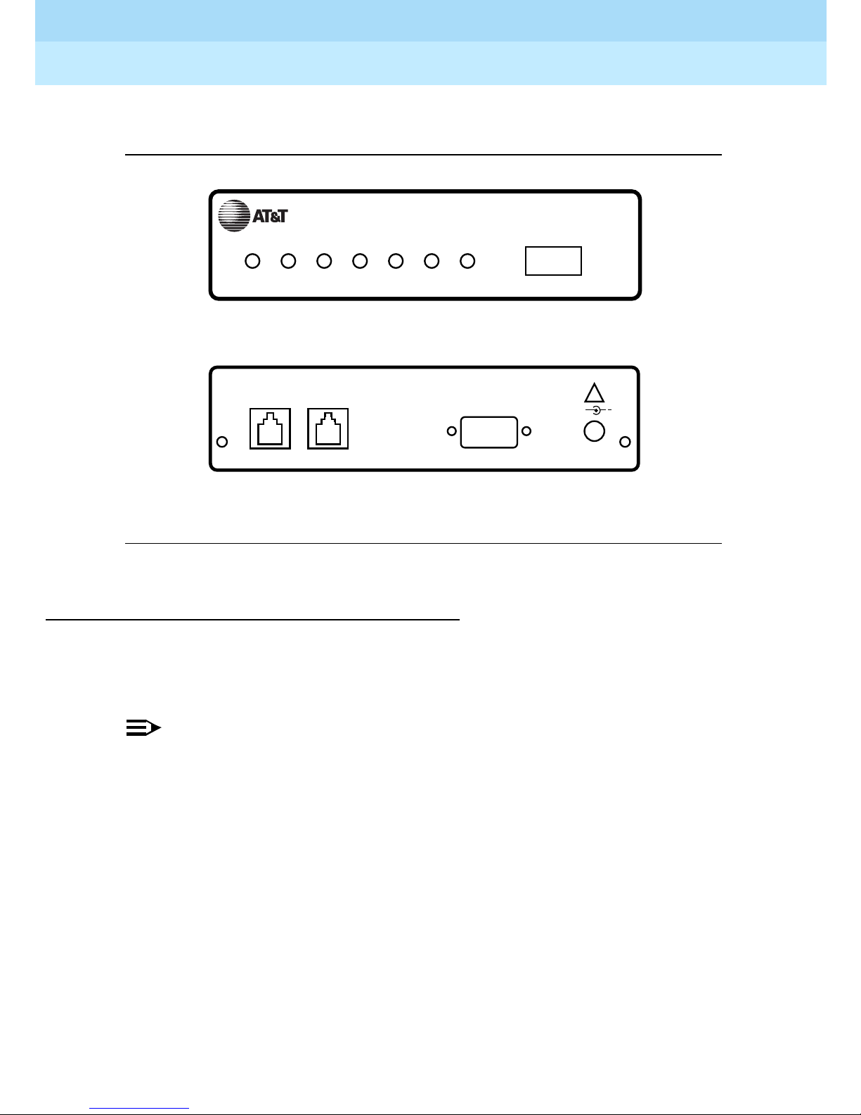
Remote Port Security Device
User’s Guide
Introduction
1
555-024-402
Install the RPSD Key between the Key user’s central office line and modem.
Issue 1
October 1996
Page 1-8Hardware Componen ts
KEY
DEFINITY RPSD
Modems
POWER RING
IN
CALL
IDLE VERIFY CONNECTED
OUT
Front
SUBSCRIBER
(MODEM) TELCO
AUX. PORT
!
+
12VDC
1A
Back
Figure 1-3. RPSD Key
The RPSD Lock works with any modem that can be used with the
communications system. Similarly, the RPSD Key works with any modem that can
be used with a terminal.
NOTE:
Version 3 of the RPSD Lock and Key works with low- and high-speed
modems up to 28.8 kbps. Versions 1 and 2 work only with low-speed
modems up to 9.6 kbps.
Page 31

Remote Port Security Device
User’s Guide
Introduction
1
555-024-402
RPSD Lock or Key Administration Terminal
The administration terminals for both Lock and Key are customer supplied. Any
administration terminal for the RPSD Lock or for the RPSD Key must meet the
following requirements:
■ Asynchronous
■ Full or half-duplex
■ Standard RS-232 interface for connection to a DCE interface
■ Baud rate in the range 300–19.2K (19.2K is the maximum rate for the DB9
AUX PORT.)
■ Any word size and parity
Use a standard RS-232 cable to connect the administration terminal to the
DB9/DB25 cable connected to the AUX. PORT of the RPSD Lock or Key. This
RS-232 cable is not supplied. The AUX. PORT is the same port used if a printer is
installed. Y ou may wish to install a switch to make changing the AUX. PORT
connection easier (for example, from a terminal to a printer).
Issue 1
October 1996
Page 1-9Hardware Componen ts
The terminal should initially be set to 9600 bps and 8 bits, no parity. These are
the factory default settings of the Lock and the Key. You may change these
parameters later on Lock, Key, and administration terminals.
RPSD Lock Administration Printer
The RPSD Lock requires a serial printer with XON/XOFF flow control.
Connect the printer (via its cable) to the DB9/DB25 cable connected to the AUX.
PORT of the RPSD Lock. The printer cable is not supplied. This is the same port
used by the administration terminal. You may wish to install a switch to make
changing the AUX. PORT connection easier (for example, from a terminal to a
printer).
Page 32

Remote Port Security Device
User’s Guide
Introduction
1
555-024-402
Software C omponents
The software for the RPSD system is contained within the hardware components
and does not need to be loaded separ ately. If you are not installing an RP SD
Key, you need only set the date and time for the RPSD Lock and, in the case of
multiple Locks, a Lock ID. If you are installing RPSD Keys, you must do some
additional initialization on the Lock(s).
Issue 1
October 1996
Page 1-10Software Components
Page 33
Remote Port Security Device
User’s Guide
Introduction
1
555-024-402
System Administration
The RPSD Lock prevents unauthorized access to the channel used by Lucent
Technologies personnel to perform m aintenance and/ or to administer your
communicati ons syst e m. When you administer the RPSD, keep in mind that
access via telephone lines is not the only means of breaching the security of your
system. A system can be breached, for example, by physically intercepti ng li nes
and adding unauthorized equipment. RPSD users may need to take many
actions to enhance overall telecommunic ation security. These actions include,
but are not limited to, providing physical security for RPSD installation sites
(locked rooms, cabinets, etc.) and wiring room sites. Monitor the RPSD System
Activity Log for patterns of activity, such as repeated denied call attempts.
Contact your computer security group for assistance.
!
Security Alert:
The Remote Port Security Device, if properly installed and managed,
provides a significant and substantial barrier to unauthorized access to a
dial-up communication port.
Issue 1
October 1996
Page 1-11System Administration
The Remote Port Security Device is not impregnable but is an important
addition to the tools and measures used by system managers to prevent
unauthorized access to dial-up ports.
Time of Day Access
The RPSD Lock can be administered to prevent access from one or more Key or
from all Keys during specified times of day. The default setting is no blockage of
access for any Key user at any time. The administrable parameters are time,
date, and user ID. Up to 14 separate time restrictions (periods of no access) may
be set for any one user ID. Time restrictions may overlap.
For example, you can use this feature to prevent any administration of the
communications system while a system administrator is not present to oversee
the administration. In this instance, you could administer the Lock to block all
users from 6:00 p.m. (18:00 hours using a 24-hour clock format) when the system
administrator leaves the office until 8:00 a.m. (08:00 hours using a 24-hour clock
format) when the system administrator returns to the office.
To specify Time of Day Access, see the instructions for the Change Restriction
command, for the List Restrictions command, and for the User Restrictions
command in Chapter 3.
Page 34

Remote Port Security Device
User’s Guide
Introduction
1
555-024-402
System Activity Log
The System Activity Log retains a log history of the last 500 status messages
generated by the Lock. Status messages include a histor y (includ ing date and
time) of the follo wing RPSD syste m act ivity:
■ Any RPSD system admini stration
■ Calls received attempting to access the host resource
■ The outcome of any access attempts (connect ed or failed)
■ The reason for the failure of call attempts
■ When the call was disconnected
As a new message is generated, the oldest message in the buffer is deleted. The
most recent 20 messages are displayed on the first page in real-time on the
RPSD Lock administration terminal. That is, the oldest message scrolls off the
screen on the administration terminal as the new message is added to the
bottom. When a printer is connected to the RPSD Lock administration term inal ,
each new message is printed at the bottom of the page as it is received from the
Lock. This allows you to create a more permanent hard-copy record of status
messages.
Issue 1
October 1996
Page 1-12System Administration
The messages are numbered consecutively from 000 to 999. If a printer is used,
any breaks in this sequence indicate an interruption of log printing.
Figure 1-4
shows a sample log history.
Page 35
Remote Port Security Device
User’s Guide
Introduction
1
555-024-402
:
> lh
--- Log History --CC85.000 7/12/96 13:23:18 KEY20 -- User Removed OK
D4E2.001 7/12/96 13:23:51 KEY19 -- User Added OK
A011.002 7/12/96 13:24:12 KEY20 -- Admin. User Added OK
6FD2.003 7/12/96 13:26:51 Call Received
12BB.004 7/12/96 13:26:59 Attempt by KEY20 [#4321] Failed
7EF4.005 7/12/96 13:27:00 KEY20 [#4321] Disconnected
BE31.006 7/12/96 13:27:06 Lucent RPSD Lock - V1.0 - Idle/Locked
A3F3.007 7/12/96 13:27:45 KEY20 -- User Unblocked OK
4C23.008 7/12/96 13:27:55 Call Received
DD52.009 7/12/96 13:28:04 KEY20 [#4321] Connected
21CC.010 7/12/96 13:32:13 KEY20 [#4321] Disconnected
66D3.011 7/12/96 13:32:15 Lucent RPSD Lock - V1.0 - Idle/Locked
B1A3.012 7/12/96 13:32:50 Call Received
D311.013 7/12/96 13:33:02 Attempt by KEY20 [#8765] Failed
C453.014 7/12/96 13:32:12 KEY20 [#8765] Disconnected
F67A.015 7/12/96 13:32:17 Lucent RPSD Lock - V1.0 - Idle/Locked
5534.016 7/12/96 13:34:59 Date Changed OK
BA14.017 7/12/96 13:43:55 Call Received
FF32.018 7/12/96 13:44:04 KEY20 [#4321] Connected
BC03.019 7/12/96 13:49:13 KEY20 [#4321] Disconnected
Issue 1
October 1996
Page 1-13System Administration
(4) Blocked User
(5) Invalid Response
-- End of List --
Figure 1-4. Sample Log History
The fields of the System Activity Log entries are:
■ Message Authentication Code / Sequence Num be r—The Message
Authentication code generated for each entry on the System Activity Log.
The code is generated to protect the integrity of the Log History. The
Message Authentication is followed by a period (“.”) and the sequence
number of each status message. The messages appear in sequence from
000 to 999 and then restart at 000.
■ Date—The date of the message
■ Time—The time the message was generated in 24-hour clock format
■ Message—The sta tus messag e
In Figure 1- 4
, KEY20 is a user ID. Information shown in square brackets is the
RPSD user ID number (as in the fifth message in Figure 1-4
assigned the same user ID; the user ID number provides a second means of
identifying the calling party .
). Users can be
Page 36

Remote Port Security Device
User’s Guide
Introduction
1
555-024-402
When a user’s access attempt fails, an access failure status message is
generated indicating the reason for the failure. Table 3-2 on page 3-43
codes and status messages, and the meaning of each failure message. The List
Statistics command can also be used to get a very brief description for each
code. For instructions on how to use the Log History command to generate a Log
History and how to use the List Statistics command, see Chapter 3, “RPSD
System Administration.”
Single Point Administration
You can use a single administration terminal or printer to administer multiple
Locks. To use a single administration terminal for multiple Locks, administer the
Locks from teletype (tty) ports via the UNIX Operating System. To us e a single
printer for multiple Locks, connect a printer-sharing device.
Issue 1
October 1996
Page 1-14System Administration
lists the
When your system includes multiple Locks , assign a Lock ID to each Lock. The
ID is included on status message s to allow yo u to asso ciate system activity with
each specific Lock. To assign an ID to a Lock, use the ID Set command
described in the “System Administrator Command Set” in Chapter 3.
Page 37
Remote Port Security Device
User’s Guide
Introduction
1
555-024-402
Block Lucent Technologies and Other Key Users
Y ou may wish to block one or more Key users from accessing the RPSD Lock. Do
this by using the Block User command. Y ou do not need to inform the Key user
that the Key has been blocked. If a blocked Key user attempts access, the Lock
blocks the attempt and sends a message to the Lock administration term in al or
printer, explaining the cause of the failed access. An example of the message
follows:
JPLock 01334 7/24/96 09:33:01 Attempt by KEY20 [#1234] Failed
(4) Blocked User
>
The following message is sent to the Key user’s administration term inal:
Issue 1
October 1996
Page 1-15System Administration
KEY20 7/24/9609:33:01Attempt Failed (4) Blocked User
>
To block a Key user or Key users, use the Block User command described in the
“System Administrator Command Set” section of Chapter 3.
Force Connect/Disconnect
The RPSD Lock can be forced to connect an incoming call from any source or to
disconnect a call in progress. A connection can be forced or a call disconnected
whether or not the caller is using an RPSD Key.
See the Force Connect and Force Disconnect commands described in the
“System Administrator Command Set” section of Chapter 3.
!
Security Alert:
Use of the Force Connect command bypasses RPSD Lock security. Use
only with extreme caution!
Page 38

Remote Port Security Device
User’s Guide
Introduction
1
555-024-402
Authorized Keys
You may authorize up to 50 RPSD Key user IDs on each RPSD Lock. Ten
additional Key user IDs are permanently reserved for Lucent Technologies
personnel to administer and maintain the commu nications sy stem, pe ripheral
equipment, or adjuncts via the RMATS port. The 10 user IDs perma nent ly
reserved for Lucent Technologies personnel cannot be deleted. However , the
permanently reserved user IDs can be blocked by issuing a block command on
the Lock or can be blocked by administering time of day restrictions on the user
IDs.
The following are the 10 permanent Lucent Technologies RPSD user IDs:
■ User IDs reserved for Lucent Technologies personn el using the INADS
system
— ATT-INADS1
Issue 1
October 1996
Page 1-16System Administration
— ATT-INADS2
— ATT-INADS3
— ATT-INADS4
■ User IDs reserved for Key users and engineers at the Technical Services
Center in Englewood, Colorado (all products):
—ATT-TSC001
—ATT-TSC002
■ User ID reserved for Lucent Technol ogies person nel at the Tier 3 location
at the Denver Works Factory:
— ATT-PECC01
■ User ID reserved for Bell Laboratories field support for System 85 and
DEFINITY
Enterprise Communications Server (ECS), Generic 2
— ATT-LABS01
■ User ID reserved for Bell Laboratories field support for System 75 and
DEFINITY ECS Generic 1
— ATT-LABS02
■ User ID reserved for Bell Laboratories field support for AUDIX
— ATT-LABS03
In addition to the 10 Lucent Technologies Key user IDs, 50 additional user IDs
are available for your own applications. These can be added to or removed from
the Lock by the Lock administrator as necessary. They can also be blocked or
restricted in the same ways as the permanent user IDs. Each of the 50
non-perman ent user IDs is matched to a separate Key.
®
Page 39

Remote Port Security Device
User’s Guide
Introduction
1
555-024-402
NOTE:
A single Key can be used to access multiple Locks.
See the Add User command for the procedure for adding users and the Remove
User command for the procedure for removing users, both described in the
“System Administrator Command Set” section of Chapter 3.
Issue 1
October 1996
Page 1-17System Administration
Page 40

Remote Port Security Device
User’s Guide
Introduction
1
555-024-402
Issue 1
October 1996
Page 1-18System Administration
Page 41

Remote Port Security Device
User’s Guide
Installation
2
2
Installation
555-024-402
Issue 1
October 1996
Page 2-1
2
This chapter describes the recommended room layout and environment,
hardware components, installation procedures, and testing for the RPSD. See
Appendix A: “Cables, Connectors, and Ports” for quick reference materials on
the installation of the hardware components.
Page 42

Remote Port Security Device
User’s Guide
Installation
2
555-024-402
Room Layo ut/Envir o nme nt
While the location of the RPSD Lock is not critical to its function, the Lock should
be kept in an equipment cabinet near the communications system modem. This
helps to protect the Lock against dust and other precipitate, as well as protecting
it against physical damage from being knocked to the floor or having things
dropped on it. You also can place it on a table near the communications system
modem. Avoid placing the Lock on top of the equipment cabinet because heat
tends to accumulate there.
NOTE:
NOTE:
A damaged Lock prohibits use of the port being protected. A secure
location for the RPSD Lock is very important to maintaining uninterrupted
service.
If more than one RPSD Lock is installed at a particular customer site, you may
stack the Locks on top of each other to save space. The Locks generate very
little heat, so you do not have to separate them.
Issue 1
October 1996
Page 2-2Room Layout/Environment
Power Supply
The RPSD Lock and the RPSD Key are both powered by ordinary AC outlets or
by AC-to-12 VDC coverters connected to AC outlets. These need not be
grounded (three-prong) outlets. If necessary, you can use extension cords.
However , it is best to connect the Lock to the Uninterruptible Power Supply (UPS)
connected to the communications system. Otherwise, a power interruption can
result in a blockage of both incoming and outgoing calls on the port being
protected. If the modem to the RMATS channel is external (System 85 and
DEFINITY Generic 2 models), the modem also should be powered from the UPS.
NOTE:
NOTE:
In a multiple Lock installation, label the Locks according to which lines they
protect to prevent confusion.
NOTE:
NOTE:
A locked port is inaccessible during a power outage for the duration of the
outage. No administration of the RPSD Lock need be done when the
outage ends. When power is restored, the RPSD Lock device automatically
comes back on-line and resets itself to an Idle/Locked state. Key
information and paramet ers are unchanged by the outage.
The power pack for the Lock draws a maximum of 18 watts. This should not
place any great strain on the UPS but should be considered with the overall draw
on the UPS.
External surge protection is optional.
Page 43

Remote Port Security Device
User’s Guide
Installation
2
555-024-402
Location of Administration Terminal or Printer
For installation purposes, it is simplest if the RPSD Lock or Key administration
terminal or printer is in the same area as the Lock or Key. If the terminal or printer
must be located at some distance from the Lock or Key (in another room, on
another floor, etc.), the limitations of the EIA-RS232 interface must be
considered.
To overcome the RS-232 restrictions, adjust the baud rate of the administration
terminal or other equipment connected to the AUX. PORT as follows:
■ Cables of 0 to 50 feet—a maximum 9600 bps
■ Cables of 50 to 100 feet—a maximum of 4800 bps
■ Cables of 100 to 2000 feet—a maximum of 2400 bps
Issue 1
October 1996
Page 2-3Room Layout/Environment
!
CAUTION:
To minimize noise induction, cable distance should not exceed 50 feet.
Set the link speed by using the Set Communications Parameters command from
the Menu of Commands. See Chapter 3, “RPSD System Admini stration” for
details on using this command with the RPSD Lock or Chapter 4, “Key
Administration and Use” for details on using this command with the RPSD Key.
Page 44

Remote Port Security Device
User’s Guide
Installation
2
555-024-402
Installation
Prior to install i n g the RPSD syste m, make sur e yo u have all the hardware
components. Also, consider these two items before you start the installation:
■ You must inform the INADS System Administrator at the local or central
Technical Support Center (TSC) when the installation will take place and
that the RMATS port will be down at that time. This ens ures that no one
tries to administer the communications system while the channel is
disconnected. You can inform the TSC by calling 800-242-2121 and
referring to Services Methods & Procedures, Talkline Case Number
910207.
■ INADS da t abase update s mus t be pe rforme d fo r th e INA D S pr odu ct
connection call to be directed through a permanent Lucent Technologies
RPSD Key. Without INADS updates, Lucent Technologies remote
maintenance operations cannot acces s the custome r’s communications
system or peripheral product.
Issue 1
October 1996
Page 2-4Installation
NOTE:
The customer must call the Technical Support Center to find out
which channel is used for Remote Maintenance and Testing Service
(RMATS). This information is only given to customers.
Page 45

Remote Port Security Device
User’s Guide
Installation
2
555-024-402
Cables, Connectors, and Ports
Table 2-1 shows the cables, connectors, and ports required to install the RPSD
system. This table includes optional connections as well as the basic
configuration.
Table 2-1. Cables, Connectors, and Ports
Part From To
Modular connector Communications system RJ11 at external
Issue 1
October 1996
Page 2-5Installation
modem
7-foot cable with
modular connector on
RPSD Lock or Key Central office line or
modem
each end
14-foot cable with
modular connector on
RPSD Lock or Key Central office line or
modem
each end
RJ11 wall jack Central office line TELCO jack on Lock
DB9/DB25 cable RPSD Lock RS-232 cable to
administration
terminal or printer or
A/B switch
EIA-RS-232 cable DB9/DB25 cable at
RPSD Lock
DB25 at
administration
terminal or printer or
A/B switch
Installing the RPSD Lock
Install the RPSD Lock between the central office line that is reserved as the
remote maintenance and administration channel and the communications
system modem (see Figure 2-1
punch-block configuration but may be set up in a number of different ways,
including an RJ11 adapter or a multiple-pair gang plug. If one is not already
present, install an RJ11 port on the central office line to facilitate installation of the
RPSD Lock and also to make subsequent service easier . Label all connections.
). The central office line is usually in a
Page 46

Remote Port Security Device
User’s Guide
Installation
2
555-024-402
The modem location depends on the type of communications system. The
modem is located:
■ on the circuit pack for System 75 and DEFINITY Generic 1.
■ external to the communications system for System 85 and DEFINITY
Generic 2.
Issue 1
October 1996
Page 2-6Installation
CO Line
(RMATS Channel)
RPSD Lock
SUBSCRIBER
(MODEM) TELCO
RED
SECURE
GREEN BYPASS
POWER MONITOR
AUX. PORT
Communications
System
Internal or
External Modem
Figure 2-1. Common RPSD Lock Configuration
ALARM
LEADS
+
12VDC
1A
115-Volt
AC Outlet
!
RPSD Administration
Terminal
Connect the RPSD Lock to the administration term inal via the AUX. PO RT on the
back of the Lock, and power it from an AC outlet or Uninterruptible Power S upply
(UPS).
On System 85 and DEFINITY Generic 2, the modems are external t o the
communicati ons syst e m. Check tha t th e modems are plugged into the UPS,
since a power outage that results in either the RPSD Lock or the modem being
inaccessible also results in the RMATS channel being inaccessible.
Page 47

Remote Port Security Device
User’s Guide
Installation
2
555-024-402
You need the following components to install the RPSD Lock:
■ RPSD Lock
■ The central office line assigned as the RMATS channel (on customer
premises)
■ The communications system modem (on customer premises)
■ 7-foot line cord with RJ11 modular connectors
■ 14-foot line cord with RJ11 modular connectors
■ DB9 (male) to DB25 (female) cable
■ RS-232 cable
■ Administration terminal for the Lock
■ RPSD Lock powe r s upply
Issue 1
October 1996
Page 2-7Installation
■ AC outlet or outlet on the UPS
NOTE:
NOTE:
The 7-foot and 14-foot telephone line cords are provided with the RPSD
Lock. If additional length cords are needed, the customer must supply
them.
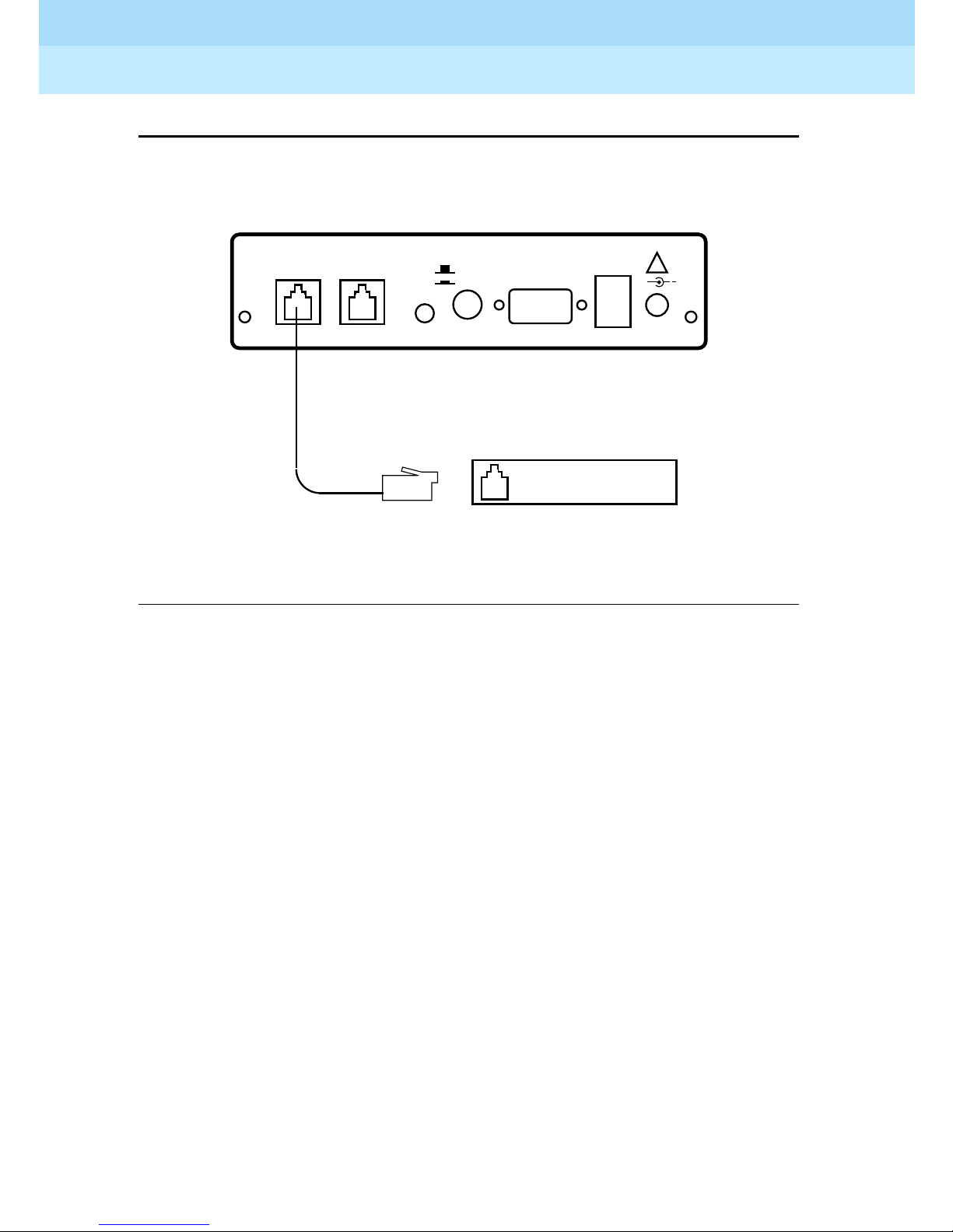
Connecting the RPSD Lock to the Central Office
Line
You need the following components to connect the RPSD Lock to the central
office line (see Figure 2-2
■ RPSD Lock
■ Central office line assigned as the RMATS channel
■ 14-foot line cord with RJ11 modular connectors
):
Page 48
Remote Port Security Device
User’s Guide
Installation
2
555-024-402
Issue 1
October 1996
Page 2-8Installation
RJ11
Connector
SUBSCRIBER
(MODEM) TELCO
RED
GREEN BYPASS
POWER MONITOR
SECURE
RPSD Lock
RJ II
Jack
Tip and Ring Wires
CO Line
(RMATS Channel)
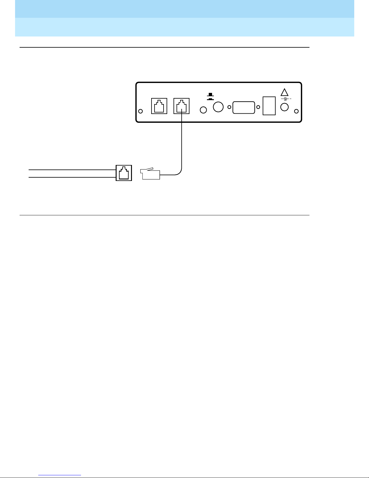
Figure 2-2 . RPSD Lo c k to Central Office Line (RM ATS Channel)
To connect the RPSD Lock to the central office line, follow these steps:
1. The customer must contact the Technical Support Center to get the port
number for the RMATS channel.
RJ11
Connector
AUX. PORT
ALARM
LEADS
!
+
12VDC
1A
2. Locate the central office line for the RMAT S port and install an RJ11
receptacle on the central office line.
3. Connect one end of the 14-foot telephone line cord with RJ11 connectors
to the central office line.
4. Plug the RJ11 connector on the other end of the telephone line cord into
the TELCO port on the back of the RPSD Lock.
Page 49

Remote Port Security Device
User’s Guide
Installation
2
555-024-402
Connecting the RPSD Lock to the
Communications System Modem
You connect the communications system modem to the RPSD Lock by using the
7-foot line cord supplied with the Lock. Obtain f urther information for the modem
from the documentation accompanying that modem.
The following components are needed to connect the RPSD Lock to the
communications syst e m modem:
■ RPSD Lock
■ Communications system modem assigned to the RMATS channel
■ 7-foot line cord with RJ11 connectors
To connect the RPSD Lock to the communications system modem , follow these
steps (see Figure 2-3
):
Issue 1
October 1996
Page 2-9Installation
1. Using the 7-foot line cord with RJ11 connecto rs on both ends, insert one
connector into the SUBSCRIBER port on the back of the RPSD Lock.
2. Insert the other RJ11 connector into the appropriate port on the
communications syst e m modem.
Page 50
Remote Port Security Device
User’s Guide
Installation
2
555-024-402
Connector
Issue 1
October 1996
Page 2-10Installation
RJ11
SUBSCRIBER
(MODEM) TELCO
RED
GREEN BYPASS
POWER MONITOR
RJ11
Connector
Figure 2-3. RPS D Lock to Modem
ALARM
SECURE
AUX. PORT
LEADS
Communications
System Modem
!
+
12VDC
1A
Page 51
Remote Port Security Device
User’s Guide
Installation
2
555-024-402
Connecting the RPSD Lock to the Administration
Terminal or Printer
You connect the RPSD Lock to the terminal or printer via the Lock’s AUX. PORT
on the back of the Lock and the RS-232 port on the terminal or printer. See Table
2-2 for the pinouts for the AUX. PORT connection. You need the following
hardware components to connect the RPSD Lock to the administration terminal
or printer:
■ RPSD Lock
■ Administration terminal or printer (printer is optional but recommended)
■ DB9/DB25 cable
■ RS-232 cable with a DB25 connector on one end and the appropriate
connector for the serial printer or administration terminal on the other end
Issue 1
October 1996
Page 2-11Installation
NOTE:
NOTE:
Install an A/B switch if you are going to connect both a terminal and a
printer. This enables the administrator to change equipment without the
trouble of disconnecting and reconnecting the plugs. Follow the directions
for connecting a terminal to the AUX. PORT to install the A/B switch.
To connect the RPSD Lock to the administration terminal or printer, follow these
steps (see Figure 2-4
):
1. Connect the DB9 end of the DB9/DB25 cable supplied with the Lock to the
AUX. PORT on the back of the RPSD Lock.
2. Connect the DB25 connector of the RS-232 cable to the DB9/DB25 cable
supplied with the Lock.
3. Connect the other end of the RS-232 cable to the terminal or printer. Be
sure this end of the RS-232 cable matches the pin descriptions in Table
2-2.
NOTE:
NOTE:
If the administration terminal or printer has a DB9 connector on its RS-232
port, you can use a straight RS-232 cable with DB9 connectors without the
DB9/DB25 cable.
Page 52
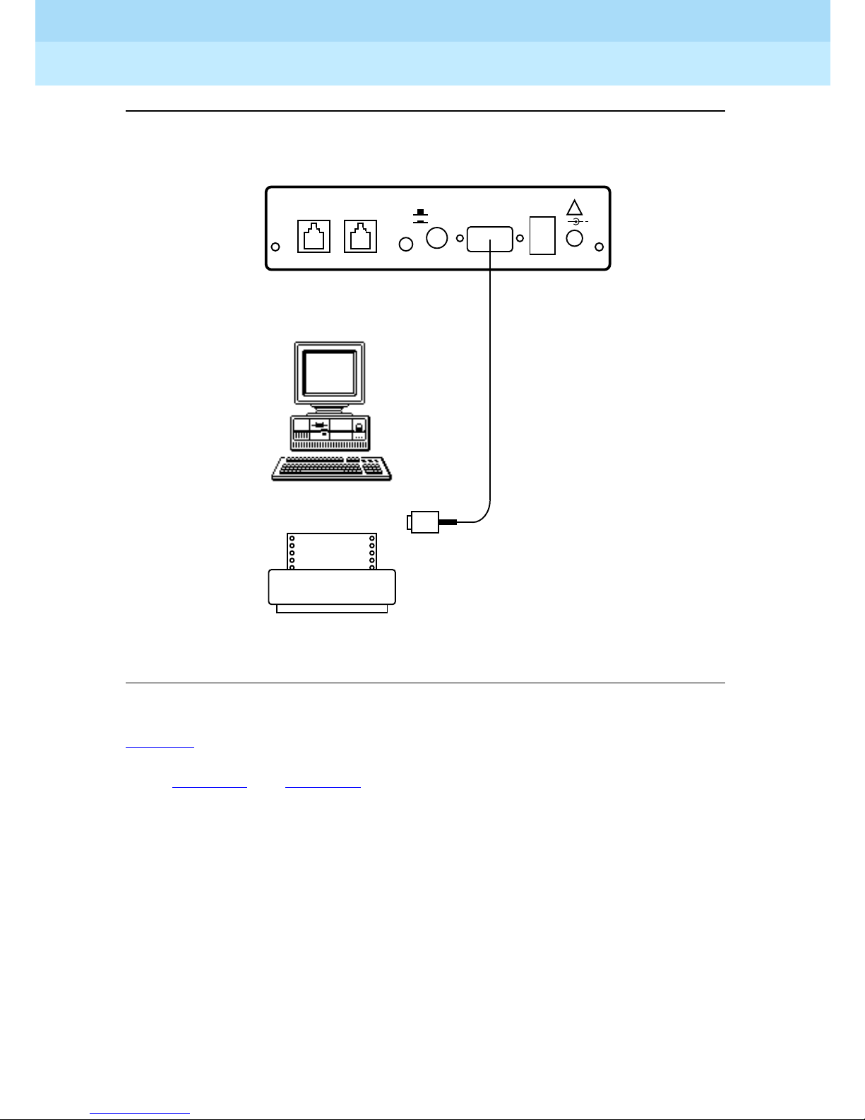
Remote Port Security Device
User’s Guide
Installation
2
555-024-402
.
Issue 1
October 1996
Page 2-12Installation
DB9 (9-Pin)/DB25 (25-Pin)
Adapter
SUBSCRIBER
(MODEM) TELCO
RED
GREEN BYPASS
POWER MONITOR
RPSD Administration
Terminal
SECURE
AUX. PORT
ALARM
LEADS
!
+
12VDC
1A
RPSD Printer
Figure 2-4. RPSD Lock to Administration Terminal or Printer
Table 2-2
describes the pinout for the Auxiliary Port connection. Obtain further
information for the terminal or printer from the documentation accompanying
them. Figure 2-5
and Figure 2-6 illustrate the pin cable connections from the
DB25 end of the Lock or Key cable to data terminal equipment (DTE) and data
communications equipment (DCE).
Page 53

Remote Port Security Device
User’s Guide
Installation
2
555-024-402
Table 2-2. Auxiliary Port, Terminal, and Printer Pinouts
Issue 1
October 1996
Page 2-13Installation
To DTE
DB9 DB25 Signal
DB25 Pin
1 Not used
2 2 TXD (input) 2 3
3 3 RXD (output) 3 2
7 4 RTS (input) 4 6
8 5 CTS (output) 5 5
6 6 DSR (output) 6 4
5 7 Ground 7 7
1 8 CD (output) 8 20
9 Positive Test Voltage
10-19 Not used
4 20 DTR (input) 20 8
To DCE
DB25 Pin
21 Not used
9 22 RI (output) 22 22
23-25 Not used
Page 54
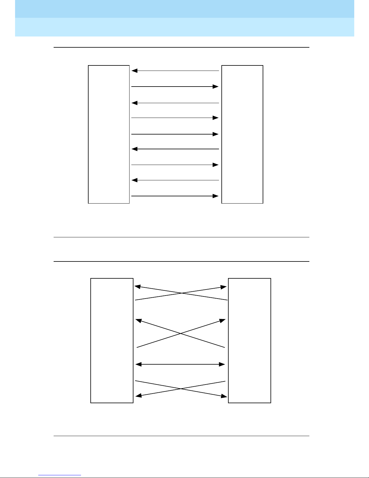
Remote Port Security Device
User’s Guide
Installation
2
555-024-402
Issue 1
October 1996
Page 2-14Installation
RPSD
(DCE)
2
3
4
5
6
7
8
20
22
Transmit Data
2
Receive Data
3
Request to Send
4
Clear to Send
5
Data Set Ready
6
Signal Ground
7
Data Carrier Detect
8
Data Terminal Ready
20
Ring Indicator
22
Terminal or Printer
(DTE)
Figure 2-5. Connections from the DB25 End of the Cable to DTE
2
3
4
5
6
7
8
20
RPSD
(DCE)
2
3
4
5
6
7
8
20
Printer
(DCE)
Figure 2-6. Connections from DB25 End of Cable to DCE
Page 55
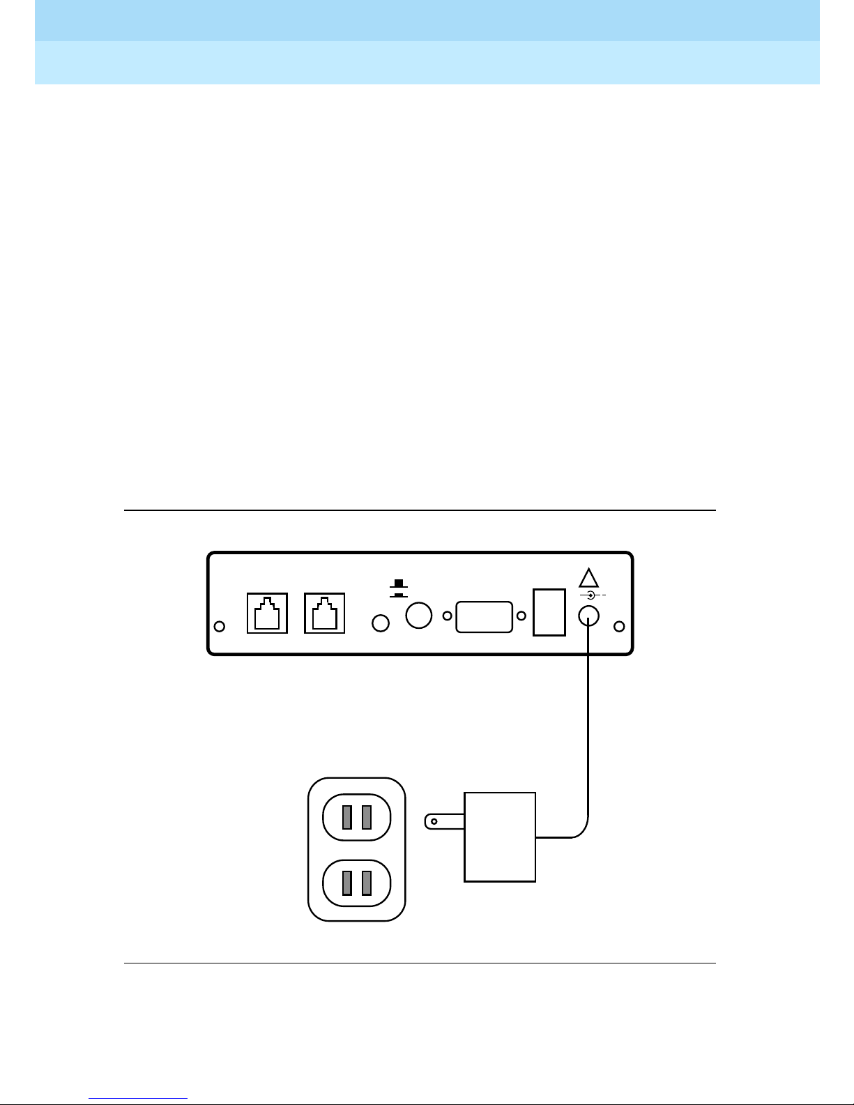
Remote Port Security Device
User’s Guide
Installation
2
555-024-402
Powering Up the RPSD Lock
To power the RPSD Lock, you need:
■ The RPSD Lock power supply
■ An AC wall outlet or an available AC outlet on the UPS. (With a System 85
or DEFINITY Generic 2 communications system, the modem is external to
the communications system and should also be powered from the UPS.)
Plug the adapter end of the power supply into the 12VDC port on the back of the
RPSD Lock and the other end into an AC wall outlet or an available outlet on the
UPS (see Figure 2-10). The red Power LED on the front panel of the Lock goes on
and remains on, while the other LEDs on the front panel of the Lock should blink
three times and then settle into a Locked condition.
If there is any failure of the LEDs (for example, they do not blink three times or the
Power light does not come on), the Lock is defective and must be replaced. See
Chapter 5 for troubleshooting. A full explanation of the LEDs for both the RPSD
Lock and Key is in Appendix B, “Front Panel LEDs.”
Issue 1
October 1996
Page 2-15Installation
SUBSCRIBER
(MODEM) TELCO
RED
GREEN BYPASS
POWER MONITOR
115-Volt
AC Outlet
SECURE
AUX. PORT
ALARM
LEADS
!
+
12VDC
1A
Figure 2-7. RPSD Lock Power Supply
Page 56
Remote Port Security Device
User’s Guide
Installation
2
555-024-402
Installing the RPSD Key
The RPSD Key is installed between the caller’ s modem and the central office line.
To install an RPSD Key, you need:
■ RPSD Key
■ Terminal
■ Modem
■ 7-foot line cord with RJ11 modular connectors
■ 14-foot line cord with RJ11 modular connectors
■ One DB9 (male) to DB25 (female) cable
■ RS-232 cable with DB25 connector on one end and the appropriate
connector for the terminal on the other end
Issue 1
October 1996
Page 2-16Installation
■ RPSD Key power supply
■ AC outlet
NOTES:
■ The 7-foot and 14-foot telephone line cords are provided with the
RPSD Key. If additional length cords are needed, the customer
must supply them.
■ The RPSD Power Monitor function may be used to provide Alarm
Lead connections for alarming RPSD Key failures. Refer to “External
Alarm” earlier in this chapter.
Connecting the RPSD Key to the Terminal
The RPSD Key is connected to the terminal via the AUX. PORT on the back of the
Key and the terminal’s RS-232 port. See Table 2-2 for the pinouts for the AUX.
PORT connection. The AUX. PORT for the Key is connected in the same manner
as the AUX. PORT for the Lock.
You need the following components to connect the RPSD Key to a termina l:
■ RPSD Key
■ DB9/DB25 cable
■ RS-232 cable with a DB25 connector on one end and the appropriate
connector for the terminal on the other end
Follow these steps to connect the Key to a terminal:
1. Connect the DB9 end of the DB9/DB25 cable supplied with the Key to the
Auxiliary Port on the Key.
2. Connect the DB25 connector of the RS-232 cable to the DB9/DB25 cable.
3. Connect the other end of the RS-232 cable to the RS-232 port on the back
of the terminal.
Page 57

Remote Port Security Device
User’s Guide
Installation
2
555-024-402
Connecting the RPSD Key to the Telephone Line
You need the following components to connect the RPSD Key to the telephone
line:
■ RPSD Key
■ Telephone line jack
■ 14-foot line cord with RJ11 modular connectors
To connect the RPSD Key to the telephone line, follow these steps:
1. Connect one end of the 14-foot telephone line cord with RJ11 connectors
to the telephone line jack.
2. Plug the RJ11 connector on the other end of the telephone line cord into
the TELCO port on the back of the RPSD Lock.
Issue 1
October 1996
Page 2-17Installation
Connecting the RPSD Key to the Modem
The RPSD Key is connected to the caller’s modem via the SUBSCRIBER port on
the back of the Key.
The following components are needed to connect the Key to the caller’s modem :
■ RPSD Key
■ Modem
■ 7-foot line cord with RJ11 connectors
To connect the Key to the caller’s modem, follow these steps (see Figure 2-3
connection is the same for the Key as for the Lock.):
1. Using the 7-foot line cord with RJ11 connectors on both ends, insert one
connector into the SUBSCRIBER port on the back of the Key.
2. Insert the other RJ11 connector into the appropriate port on the caller’s
modem.
Powering Up the RPSD Key
; the
The RPSD Key may be in one of two conditions upon power-up: initialized or
uninitialized. The response of the Key upon power-up is different depending on
which condition it is in. Both conditions are described below.
To power the RPSD Key, you need:
■ The RPSD Key power supply
■ An AC w a l l outlet
Plug one end of the power supply into the 12VDC port on the back of the RPSD
Key and the other end into an AC wall outlet.
Page 58

Remote Port Security Device
User’s Guide
Installation
2
555-024-402
Power-Up Behavior of Initialized Key
With an initialized Key, the red POWER LED on the front panel of the RPSD Key
turns on and remains on permanently. The other LEDs on the front panel of the
RPSD Key should blink three times and then settle into a condition with only the
IDLE and POWER LEDs lit. If the LEDs do not blink three times or the POWER
LED does not come on, the Key is defective and must be replaced.
Power-Up Behavior of Uninitialized Key
With an uninitialized Key, the left four LEDs should all light up upon power-up. If
any other behavior occurs, there is a firmware error and the Key should be
replaced.
Testing an Uninitialized Key
Issue 1
October 1996
Page 2-18Installation
Test an RPSD Key that has not been initialized by following these steps:
1. Connect either a telephone or a terminal with a modem to the
SUBSCRIBER port on the back panel of the Key.
2. Dial the associated RPSD Lock, either directly via the telephone or via an
application on the terminal.
If the connection is good, the yellow VERIFY light comes on first, followed by the
green CONNECTION light. This should occur in less than 30 seconds. The
CONNECTION LED remains lit until the call is ended. If the connection fails, the
red IDLE light comes on.
Initializing the RPSD Lock
Initialization of the RPSD Lock is the responsibility of the RPSD system
administrator. The technician who installs the Lock tests the system to make sure
it is running properly but does not set any additional parameters or make any
changes to the system defaults.
To initialize the RPSD Lock where no additional RPSD Keys are being installed,
use the:
■ Date Set command
■ Clock Set command
If more than one RPSD Lock is being installed, use the ID Set command to allow
identification of the Lock when viewing system activity messages. Each Lock’s ID
will be prepended to each system activity message.
If RPSD Keys are being installed, administer the Lock with the Add User
command. This step permits the Key to access the Lock. Use the Test User
command to make sure that the new Key works properly.
Page 59
Remote Port Security Device
User’s Guide
Installation
2
555-024-402
The commands and their use are described in “System Administrator Command
Set” in Chapter 3.
NOTE:
NOTE:
The installer will not have an administration terminal to use for initialization.
This must be supplied by the customer and must be ready for use when
initialization takes place.
Auxilia ry P or t Se ttin g s
You must also set the link speed, character length, and parity on whatever
equipment (administration ter m inal or printer) you have attached to the Auxiliary
Port. The default for the AUX. PORT is 9600 bps, 8 bit, no parity. See Chapter 3,
“RPSD System Administration” for the use of the Set Communications Parameters
command to change the default settings, if desired, on the RPSD Lock. See
Chapter 4, “Key Administration and Use” for the Set Communications Parameters
command to change the default settings, if desired, on the RPSD Key.
Issue 1
October 1996
Page 2-19Installation
Initializing the RPSD Key
Initialization of an RPSD Key involves both the Key and the RPSD Lock. On the
Lock, you must add the Key User ID in question by using the Add User
command. See “System Admin istrator Command Set” in Chapter 3 for the
procedure for using the Add User command.
On the Key, the following commands are used for initializing the device:
■ Set User ID
■ Set Secret Key
■ Set Device Number
■ Date Set
■ Clock Set
■ Set Log ID (optional)
All of these commands must be used when initializing the RPSD Key device. A
description of the commands and the procedures for their use appear in
Chapter 4, “Key Administration and Use.”
NOTE:
NOTE:
The installer will not have an administration terminal to use for initialization.
This must be supplied by the customer and must be ready for use when
initialization takes place.
Page 60

Remote Port Security Device
User’s Guide
Installation
2
555-024-402
Testing the RPSD Lock Installation
The Self-Check tests the health of the RPSD Lock. If the correct response is
received when the test is run, the RPSD Lock is functioning properly.
Fol low t hese s teps to perf orm the Sel f -Check:
1. Dial the RMATS channel from a touch-tone telephone.
When the call is answered, you hear a short tone, indicating a connection
to the RPSD Lock.
2. Press 1 ✱ on the telephone pad.
If the response is 3 quick tones followed by the RPSD Lock disconnecting,
the Lock is functioning properly.
3. Have the technical suppor t center call the RMATS channel. If access is
successful, the installation is working properly. If access is unsuccessful,
refer to Chapter 5, “Troubleshoot ing .”
Issue 1
October 1996
Page 2-20Testing th e RPSD Lock Ins tallation
After a successful access of the port has shown the Lock to be working properly,
try dialing out through the RMATS channel via the Lock. If you have trouble with
making an outgoing call, the tip and ring leads probably are reversed. Reverse
the current connection of the tip and ring leads from the central office line to the
RPSD Lock and dial out again. If a failure occurs, something is wrong with the
Lock (see Chapter 5, “Troubleshooting”), and you must replace it.
If all tests are passed successfully, installation is complete for the technician.
Lock initialization can now be performed by the RPSD system administrator.
Page 61

Remote Port Security Device
User’s Guide
RPSD System Administration
3
3
RPSD System Administration
555-024-402
The RPSD Lock prevents unauthorized access to the RMATS channel on your
communicati ons syst e m. When you administer the RPSD, keep in mind that
access via telephone lines is not the only means of breaching the security of your
system. A system can be breached, for example, by physically intercepti ng li nes
and adding unauthorized equipm ent. RPSD users may take many actions to
enhance overall telecommunica tion secu rity. These actions include, but are not
limited to, providing physical security for RPSD installation sites (locked rooms,
cabinets, etc.) and wiring room sites. Monitor the RPSD System Activity Log for
patterns of activity, such as repeated denied call attempts. Contact your
computer security group for assistance.
Issue 1
October 1996
Page 3-1
3
NOTE:
Save the seed value for the authentication algorithm in a protected place, in
case equipment needs to be replaced at a later date.
!
Security Alert:
The Remote Port Security Device, if properly installed and managed,
provides a significant and substantial barrier to unauthorized access to a
dial-up communication port.
Page 62

Remote Port Security Device
User’s Guide
RPSD System Administration
3
555-024-402
Menu of Commands
Use the RPSD System Administrator Command Set to set RPSD Lock system
parameters (such as time, date, communications specifications, etc.), to
administer Key user capabilities and restrictions, and to list user information and
system activity logs. See Table 3-1
function.
The Menu of Commands available to the system administrator is shown in
Figure 3-1
.
Issue 1
October 1996
Page 3-2Menu of Command s
for a quick reference of these command s by
- Menu of Commands ---
A - Add User LH - Log History FC - Force Connect
B - Block User AH - Access History FD - Force Disconnect
U - Unblock User FH - Failure History
T - Test User AA - Admin. Access Hist D - Date Set
R - Remove User AF - Admin. Failure His C - Clock Set
L - List User Table I - ID Set
ST - Status Display SC - Set Comms. Params
CR - Change Restriction LS - List Statistics AS - AUX Security
ON/Off
LR - List Restrictions RS - Reset Statistics
UR - User Restrictions Q - Quit Admin. session
-- For Help Type ‘?’ Followed by Command --
Figure 3-1. Menu of Commands
NOTE:
The menu of Commands is available at any time by pressing on the
ENTER
RPSD administration term inal. The com man ds are not case sensitive.
Page 63

Remote Port Security Device
User’s Guide
RPSD System Administration
3
555-024-402
Use Table 3-1 as a reference for command use.
Table 3-1. Command Usage Quick Reference
Function Command Page Ref.
New system installation or new Key added
Set the current date Date Set page 3-25
Set the current time Clock Set page 3-24
Set a unique identifier for the RPSD Lock ID Set page 3-31
Issue 1
October 1996
Page 3-3Menu of Command s
Set the communications link speed,
character length, and parity on the serial
port.
Add administrative, RPSD/Key
(non-administrative) user to Lock
Determine code to be matched by a
code from the user
Enable or disable security on the AUX
(administrative) port
Specify time restrictions for access to the
Lock
Assign specified time restrictions to
users
Block users from access to the RMATS
channel
Set Comm.
page 3-47
Parameters
Add User page 3-6
Test User page 3-50
AUX Security page 3-19
Change
page 3-22
Restric tions
User
page 3-52
Restrictions
Block User page 3-21
Other administrative procedures:
Display a help screen for a command Help (?) page 3-54
Unblock users from access to RMATS
channel
Remove user from RPSD Lock access Remove User page 3-45
Unblock User page 3-51
Page 64
Remote Port Security Device
User’s Guide
RPSD System Administration
3
555-024-402
Table 3-1. Command Usage Quick Reference — Continued
Function Command Page Ref.
Issue 1
October 1996
Page 3-4Menu of Command s
Override RPSD Lock security and allow
Force Connect page 3-29
individual call access to host resource
Disconnect a call in progress Force
page 3-30
Disconnect
Display the version, date, time,
Status Display page 3-48
communications parameters , and
current status of the RPSD Lock
Reset the access attempt statistics to
zero
Reset
Statistics
page 3-46
Terminate an administrative session Quit page 3-44
User information lists:
List user ID, whether the user is blocked,
List User Table page 3-36
user type (permanent, administrative,
RPSD/Key [non-administrative]),
password or passkey requirement for
administrative users, and assigned
restrictions
List specific time periods and days
during which time restrictions may be
placed on one or more users
Show whether a user is blocked and/or
restricted and the code to be matched
by a code from the user
System activity histories:
List the last 500 System Activity Log
messages, including Messa ge
Authentication Code, message
sequence number, date and time of
message, and status message
List
page 3-32
Restrictions
Test User page 3-50
Log History page 3-40
Page 65

Remote Port Security Device
User’s Guide
RPSD System Administration
3
555-024-402
Table 3-1. Command Usage Quick Reference — Continued
Function Command Page Ref.
Issue 1
October 1996
Page 3-5Command Functions
List the details of the last 500 RMATS
channel access calls (incoming and
outgoing), including Message
Authentication Code, message
sequence number, date, time, user ID,
device number, and duration of the call
List the details of the last 500 failed
access attempts including Message
Authentication Code, message
sequence number, date, time, user ID,
device number, and failure reason
List the details of the last 100
administrative access attempts including
Message Authentication Code,
message sequence number, date, time,
user ID, and duration of the call
List the details of the last 100 failed
administrative access attempts including
Message Authentication Code,
message sequence number, date, time,
user ID, and failure reason
Access History page 3-11
Failure History page 3-26
Administra-
page 3-14
tive Access
History
Administra-
page 3-17
tive Failure
History
List a statistical summary of call attempts
and failures since the last reset and
cumulative totals
Comma nd Functions
The following pages contain a description of the RPSD System Administrator
Commands and command syntax for the RPSD Lock. The commands are in
alphabetical order. Also described at the end of this chapter is the method of
accessing the help screens that accompany the Menu of Comma nds.
List Statistics page 3-34
Page 66
Remote Port Security Device
User’s Guide
RPSD System Administration
3
555-024-402
A—Add User
Syntax and Parameters
To add an RPSD Key user:
Issue 1
October 1996
Page 3-6Command Functions
a <user_id>,[secret_key]
ENTER
To add an administrative user with the capability to access the RPSD Lock to
change Lock parameters:
a <user_id>,[secret_key], a<authenti cation_ mode >
ENTER
Parameter D escription
a Add User command
<user_id> A unique identifier selected by the system administrator.
The user ID may be up to 10 characters long and is not
case sensitive.
[secret_key] The the pre-defined number of up to 14 hexadecimal
digits used to administer a single Key for multiple Locks.
This parameter can be specified by the system
administrator or randomly assigned by the Lock. If this
field is omitted (the field must be delimited by a comma), it
is randomly generated by the Lock.
a The administrative user designation
<authentication
_ mode>
Identifies the authentication method if AUX Security is
enabled. The valid values are:
The default is w. If you only enter “a,” the system internally
adds a “w.”
k = administrative user must authe nticate to the
AUX port using a passkey
w = administrative user must authenticate to the
AUX port using a password
Page 67

Remote Port Security Device
User’s Guide
RPSD System Administration
3
555-024-402
Descr iption
Use the Add User command to add an RPSD Key user or an administrative user
to the list of users on the Lock. A total of 60 RPSD/Key (non-administrative) users
and administrative users are allowed on each Lock. Of the 60 users, 10 are
permanent users reserved for Lucent Technologies personnel and cannot be
removed. The following are the 10 permanent Lucent Tech nolog ies RPSD user
IDs:
■ User IDs reserved for Lucent Technologies personn el using the INADS
system
— ATT-INADS1
— ATT-INADS2
— ATT-INADS3
Issue 1
October 1996
Page 3-7Command Functions
— ATT-INADS4
■ User IDs reserved for Key users and engineers at the Technical Services
Center in Englewood, Colorado (all products):
—ATT-TSC001
—ATT-TSC002
■ User ID reserved for Lucent Technol ogies person nel at the Tier 3 location
at the Denver Works Factory:
— ATT-PECC01
■ User ID reserved for Bell Laboratories field support for System 85 and
DEFINITY
®
Enterprise Communications Server (ECS), Generic 2
— ATT-LABS01
■ User ID reserved for Bell Laboratories field support for System 75 and
DEFINITY ECS Generic 1
— ATT-LABS02
■ User ID reserved for Bell Laboratories field support for AUDIX
— ATT-LABS03
In addition to normal access capabilities, administrative users can gain access
to the RPSD Lock to change Lock parameters. If the AUX Security feature is
enabled, the administrative user must use a password or a passkey device
associated with the user ID to authenticate his or her administrative access
capability. See “Passkey Authentication” in Chapte r 4 for instructions for the
passkey authentication process.
When the administrative user is added with a password requirement (a w ent ere d
in the <authentication_mode> parameter), the assigned password is entered at
the “Enter Password” prompt and then entered again at the “Verify Password”
prompt. This ensures that the intended password is typed correctly. The unique
Page 68
Remote Port Security Device
User’s Guide
RPSD System Administration
3
555-024-402
password contains up to 15 alphanumeric characters consisting of any printable
ASCII character, including a space.
NOTE:
Passwords are case sensitive. While entering the password, note whether
the password characters are entered in upper or lower case.
A single Key can be used to access multiple Locks. This is done by entering
information in the [secret_key] parameter when adding that Key. When an
administrative user is added with a passkey requirement, the [secret_key]
parameter is required by the encryption device to verify the user’ s identity during
authentication. The [secret_key] parameter is not required when an
administrative user is added with a password requirement.
The same secret key information is used when adding that Key to other Locks.
The information is used to generate the test response. The secret key chosen by
the administrator is the key information to be added to the RPSD Key. If this
option is not used, the RPSD Lock generates the secret key information
randomly.
Issue 1
October 1996
Page 3-8Command Functions
The RPSD Lock returns secret information and a test response when a user is
added. This information is used to initialize the RPSD Key, so make sure to note
the information.
In any situation where the RPSD Key is already initialized for use on another
Lock, the existing [secret_key] parameter should be specified when adding the
user to each additional Lock.
!
Security Alert:
Be careful to maintain the security of the information. The user ID will always
be associated with that particular Key and its secret information and test
response.
Before newly added Key users can gain access via the Lock system, the new
Key must be initialized. See the “Initialization Function” section in Chapter 4 for
the procedure.
Page 69

Remote Port Security Device
User’s Guide
RPSD System Administration
3
555-024-402
Sample Command and Response
Adding a non-administrative user without specifying the [secret_key] parameter:
> a KEY20,,
JPLock01 443 08/12/96 13:14:22 KEY20 -- User Added OK ->
Enter this secret key into the RPSD/Key Unit
F37B 159D 6ABE 3E
Test Response is: 8119704
>
Issue 1
October 1996
Page 3-9Command Functions
Adding a non-administrative user with
> a KEY20,F47B159D6ABE3E
JPLock02 443 08/14/96 01:57:43 KEY21 -- User Added OK ->
Enter this secret key into the RPSD/Key Unit
F47B 159D 6ABE 3E
Test Response is: 4296425
>
the [secret _key] parameter specified:
Adding an administrative user requiring password authentication:
> a JOE,,AW
Enter Password >***************
Verify Password >***************
JPLock02 443 08/14/96 01:57:43 KEY21 -- Admin. User Added OK ->
Page 70
Remote Port Security Device
User’s Guide
RPSD System Administration
3
555-024-402
Adding an administrative user requiring passkey authentication:
> a KEY20,,ak
JPLock02 443 08/14/96 01:57:43 KEY21 -- Admin. User Added OK ->
Enter These Digits into PassKey as Key1 or Key2:
7652 0034 = 2106 4704 = 3320 =
Test Challenge: 1234567 ...Reply: 832-5113
>
If a user with an existing passkey is assigned to a new key, the existing passkey
can be entered so a new one does not have to be assigned:
Issue 1
October 1996
Page 3-10Command Functions
> a KEY20,58940085427656086626,ak
JPLock02 443 08/14/96 01:57:43 KEY20 -- Admin. User Added OK ->
Enter These Digits into PassKey as Key1 or Key2:
5894 0085 = 4276 5608 = 6626 =
Test Challenge: 1234567 ...Reply: 765-3241
>
Page 71

Remote Port Security Device
ENTER
User’s Guide
RPSD System Administration
3
555-024-402
AH— Ac ce ss History
Syntax and Parameters
Issue 1
October 1996
Page 3-11Command Functions
ah [-] [ALL]
Description
ENTER
Parameter Description
ah Access History command
[-] Include this parameter to list the Access History in
descending order by message sequence number. If this
parameter is not used, the Access History is listed in
ascending order.
[ALL] Use this parameter to remove the page breaks and list the
entire Access History buffer. Press to pause and
ENTER
resume the report on the screen. If this parameter is not
used, the report is listed 20 messages to a page.
Use the Access History command to display details on the last 500 incoming or
outgoing calls attempts using the RMATS channel. The details include the date,
time, user ID, device number, and duration of the call.
To protect the integrity of the Access History, a Message Authentication Code is
generated and shown with each Access History entr y. The Message
Authentication Code is followed by a period (“.”) and the sequence number of
the message, for example, “CC85.000,” where “CC85” is the Message
Authentication Code and “000” is the message sequ ence num ber.
If the [-] and [ALL] parameters are not used, the messages are displayed in
ascending order by message sequence numb er, 20 to a page. “- More to Come
-” appears at the bottom of the each page except the last page, and “- End of
List -” appears at the bottom of the last page. Press to move from page
ENTER
to page. When you reach the last page (indicated by “- End of List -”), press
ENTER
to return to the menu of commands.
When you want to capture a long Access History to a file on a computer, include
the [ALL] paramet er. Page breaks are removed and the entire Access History is
listed. To pause the report shown on the screen, press . To resume the
ENTER
report on the screen, press again.
Page 72
Remote Port Security Device
User’s Guide
RPSD System Administration
3
555-024-402
To capture an A ccess History, use a communications software package (such as
ProComm). After you save the Access History as a file, you can open it in a word
processing application and print it.
To show the Access History in descending order by message sequence number,
include the [-] parameter.
Sample Command and Response
> ah
--- Access History -- Seq Date Time User ID Device # Duration
E2C1.000 08/16/96 13:08:51 ATT-INADS1 12345 0: 0:20
B1A3.001 08/16/96 13:09:42 ATT-INADS1 12345 1:20:33
CC34.002 08/16/96 15:12:06 <Outdial> 0: 5:08
D4E2.003 08/16/96 15:20:51 <Outdial> 0: 2:14
12BB.004 08/16/96 15:24:19 ATT-INADS2 72333 0: 8:46
7EF4.005 08/16/96 15:48:01 ATT-INADS2 72333 0: 1:59
BE31.006 08/16/96 15:58:23 KEY11 82545 0: 7:22
A3F3.007 08/16/96 16:08:51 KEY11 82545 0: 3:20
4C23.008 08/17/96 08:08:18 <Outdial> 0: 9:49
DD52.009 08/17/96 08:28:13 ATT-INADS1 12345 0:28:11
21CC.010 08/17/96 08:58:37 ATT-INADS1 12345 0: 1:02
66D3.011 08/17/96 14:03:32 <Outdial> 0: 6:15
B1A3.012 08/17/96 14:09:53 ATT-INADS1 12345 0: 3:38
D311.013 08/17/96 14:18:10 KEY16 96549 0:24:22
C453.014 08/17/96 14:44:44 KEY16 96549 0: 0:58
F67A.015 08/18/96 09:18:51 KEY12 37827 0:10:04
55E5.016 08/18/96 09:21:48 KEY12 37827 0: 0:47
E7A1.017 08/18/96 11:31:25 <Outdial> 0:13:03
BA14.018 08/18/96 11:48:11 <Outdial> 0:29:34
BC03.019 08/18/96 13:28:31 ATT-INADS1 12345 2:56:05
Issue 1
October 1996
Page 3-12Command Functions
-- End of List --
Page 73

Remote Port Security Device
User’s Guide
RPSD System Administration
3
555-024-402
The fields of the Access History screen are:
Seq The Message Authentication Code and mess age sequence
Date The date that the access took place
Time The time that the access call came in
User ID The user ID of the Key used to access the RMATS channel.
Issue 1
October 1996
Page 3-13Command Functions
number generated for each Access History entry. The code
is generated to protect the integrity of the Access History.
The Message Authentication Code is followed by a period
(“.”) and the sequence number of each status message. The
messages are numbered in sequence from 000 to 999 and
then restart at 000.
If the call was an outgoing call on the channel, no user ID is
displayed but the call is identified as <Outdial>.
Device # The device number of the Key used to access the RMATS
channel. The device number is a number assigned to the
Key by the Key user at initialization. No device number
appears for an outgoing call.
Duration The length of time that the call was connected in hours,
minutes, and seconds
Page 74

Remote Port Security Device
User’s Guide
RPSD System Administration
3
555-024-402
AA—A d mi n istr ative Access H ist or y
Syntax and Parameters
Issue 1
October 1996
Page 3-14Command Functions
aa [-] [ALL]
Description
ENTER
Parameter Description
aa Administrative Access History command
[-] Include this parameter to list the Administrative Access
History in descending order by message sequence number.
If this parameter is not used, the Administrative Access
History is listed in ascending order.
[ALL] Use this parameter to remove the page breaks and list the
entire Administrative Access History buffer. Press to
ENTER
pause and resume the report on the screen. If this
parameter is not used, the report is listed 20 messages to a
page.
Use the Administrative Access History command to display details on the last
100 administrative access attempts. The details include the date, time, user ID,
and duration of the call.
To protect the integrity of the Administrative Access History, a Message
Authentication Code is generated and shown with each Administrative Access
History entry. The Message Authentication Code is followed by a period (“.”) and
the sequence number of the message, for example, “CC85. 000,” where “CC85”
is the Message Authentication Code and “000” is the mess age seque nce
number.
If the [-] and [ALL] parameters are not used, the messages are displayed in
ascending order by message sequence numb er, 20 to a page. “- More to Come
-” appears at the bottom of the each page except the last page, and “- End of
List -” appears at the bottom of the last page. Press to move from page
ENTER
to page. When you reach the last page (indicated by “- End of List -”), press
ENTER
to return to the menu of commands.
When you want to capture a long Administrative Access History to a file on a
computer, include the [ALL] parameter. Page breaks are removed and the entire
Administrative Access History is listed. T o pause the report shown on the screen,
press . To resume the report on the screen, press again.
ENTER ENTER
Page 75

Remote Port Security Device
User’s Guide
RPSD System Administration
3
555-024-402
To capture an Administrative Access History, use a communications software
package (such as ProComm). After you save the Administrative Access History
as a file, you can open it in a word processing application and print it.
To show the Administrative Access History in descending order by message
sequence number, include the [-] parameter.
Sample Command and Response
> ah
--- Admin. Access History -- Seq Date Time User ID Duration
E2C1.000 08/16/96 13:08:51 KEY20 0: 0:20
B1A3.001 08/16/96 13:09:42 KEY11 1:20:33
CC34.002 08/16/96 15:12:06 KEY20 0: 5:08
D4E2.003 08/16/96 15:20:51 KEY20 0: 2:14
12BB.004 08/16/96 15:24:19 ATT-INADS2 0: 8:46
7EF4.005 08/16/96 15:48:01 ATT-INADS2 0: 1:59
BE31.006 08/16/96 15:58:23 KEY11 0: 7:22
A3F3.007 08/16/96 16:08:51 KEY11 0: 3:20
4C23.008 08/17/96 08:08:18 KEY20 0: 9:49
DD52.009 08/17/96 08:28:13 ATT-INADS1 0:28:11
21CC.010 08/17/96 08:58:37 ATT-INADS1 0: 1:02
66D3.011 08/17/96 14:03:32 KEY11 0: 6:15
B1A3.012 08/17/96 14:09:53 ATT-INADS1 0: 3:38
D311.013 08/17/96 14:18:10 KEY11 0:24:22
C453.014 08/17/96 14:44:44 KEY20 0: 0:58
F67A.015 08/18/96 09:18:51 KEY20 0:10:04
55E5.016 08/18/96 09:21:48 KEY11 0: 0:47
E7A1.017 08/18/96 11:31:25 KEY20 0:13:03
BA14.018 08/18/96 11:48:11 KEY20 0:29:34
BC03.019 08/18/96 13:28:31 ATT-INADS1 2:56:05
Issue 1
October 1996
Page 3-15Command Functions
-- End of List --
Page 76

Remote Port Security Device
User’s Guide
RPSD System Administration
3
555-024-402
The fields of the Administrative Access History screen are:
Seq The Message Authentication Code and mess age sequence
Date The date that the access took place
Time The time that the access call came in
User ID The user ID of the administrative Key used to access the
Issue 1
October 1996
Page 3-16Command Functions
number generated for each Administrative Access History
entry. The code is generated to protect the integrity of the
Administrative Access History. The Message Authentication
Code is followed by a period (“.”) and the sequence number
of each status message. The messages are numbered in
sequence from 000 to 999 and then restart at 000.
RPSD/Lock syste m
Duration The length of time that the call was connected in hours,
minutes, and seconds
Page 77

Remote Port Security Device
User’s Guide
RPSD System Administration
3
555-024-402
AF—Administrative Failure Histor y
Syntax and Parameters
Issue 1
October 1996
Page 3-17Command Functions
af [-] [ALL]
Descr iption
ENTER
Parameter Description
af Administrative Failure History command
[-] Include this parameter to list the Administrative Failure
History in descending order by message sequence number.
If this parameter is not used, the Administrative Failure
History is listed in ascending order.
[ALL] Use this parameter to remove the page breaks and list the
entire Administrative Failure History buffer. Press to
ENTER
pause and resume the report on the screen. If this
parameter is not used, the report is listed 20 messages to a
page.
Use the Administrative Failure History command to display a log of the last 100
failed administrative access attempts. The details include the date, time, user ID,
and a failure reason code.
To protect the integrity of the Administrative Failure History, a Message
Authentication Code is generated and shown with each Administrative Failure
History entry. The Message Authentication Code is followed by a period (“.”) and
the sequence number of the message, for example, “CC85. 000,” where “CC85”
is the Message Authentication Code and “000” is the mess age seque nce
number.
If the [-] and [ALL] parameters are not used, the messages are displayed in
ascending order by message sequence numb er, 20 to a page. “- More to Come
-” appears at the bottom of the each page except the last page, and “- End of
List -” appears at the bottom of the last page. Press to move from page
ENTER
to page. When you reach the last page (indicated by “- End of List -”) page,
press to return to the menu of commands.
ENTER
When you want to capture a long Administrative Failure History to a file on a
computer, include the [ALL] parameter. Page breaks are removed and the entire
Administrative Failure History is listed. To pause the report shown on the screen,
press . To resume the report on the screen, press again.
ENTER ENTER
Page 78

Remote Port Security Device
User’s Guide
RPSD System Administration
3
555-024-402
To capture an Administrative Failure History, use a communicat ions software
package (such as ProComm). After you save the Administrative Failure History
as a file, you can open it in a word processing application and print it.
To show the Administrative Failure History in descending order by message
sequence number, include the [-] parameter.
Sample Command and Response
> af
--- Admin. Failure History -- Seq. Date Time User ID Reason
CC85.000 08/16/96 13:08:51 KEY22 3
-- End of List --
Issue 1
October 1996
Page 3-18Command Functions
The fields of the Failure History screen are:
Seq The Message Authentication Code and mess age sequence
number generated for each Failure History entry. The code
is generated to protect the integrity of the Failure History.
The Message Authentication Code is followed by a period
(“.”) and the sequence number of each status message. The
messages are numbered in sequence from 000 to 999 and
then restart at 000.
Date The date of the access failure
Time The time of the access failure
User ID The user ID of the RPSD Key used to attempt to access the
channel
Device # The device number of the Key used to access the channel.
The device number is a number assigned to the Key by the
Key user at initialization.
Reason The call access failure code. The codes and their
explanations are provided in Table 3-2 on page 3-43
List Statistics command can also be used to get a very brief
description for each code (see instructions on page 3-34).
. The
Page 79

Remote Port Security Device
User’s Guide
RPSD System Administration
3
555-024-402
AS—AUX Security
Syntax and Parameters
To determine AUX Port status:
ENTER
as
To enable AUX Security:
Issue 1
October 1996
Page 3-19Command Functions
as on
To disable AUX Security:
as off
Descr ip tion
Use the AUX Security command to determine AUX (administrative) por t status
and to enable and disable security on the AUX port.
ENTER
ENTER
Parameter Description
as A UX Sec urity comma nd
on Enables A UX Se curity
off Disables AUX Security
!
Security Alert:
AUX Security should not be enabled until administrative users are added. If
AUX Security is ON and no administrative users have been added, an
appropriate warn i ng m e ssag e will be displayed when the RPSD system is
powered up.
When AUX Port security is disabled, administrative access to the RPSD system is
allowed without authentication by any terminal connected to the AUX port.
When AUX Port security is enabled, the administrative user must press
twice to activate an administrative session and make changes to the RPSD
system or to view status rep orts. The administrative user must use a password or
passkey to authenticate access per m issions and begin the administ rative
session.
ENTER
Page 80
Remote Port Security Device
User’s Guide
RPSD System Administration
3
555-024-402
When the administrative session is complete, use the Quit command to terminate
the session (see instructions on page 3-40).
If AUX security is enabled and no administrative session is activated, log
messages are sent to the AUX port only if the Data Terminal Ready (DTR) is high.
When the administrative session is terminated, the Carrier Detect Signal (CD)
goes low for one second.
If DTR goes low during an administrative session, the session is terminated.
Sample Command and Response
Determining AUX port status (AUX Security command with no arguments):
Issue 1
October 1996
Page 3-20Command Functions
> as
AUX Port Security is OFF
>
Enabli ng A U X Security:
> as on
013 07/18/96 04:19:40 AUX Port Security is ON
>
Disabling AUX Security:
> as off
014 07/18/96 04:20:53 AUX Port Security is OFF
>
NOTE:
When the current administrative session is completed by using the Quit
command, AUX port security is enabled when a new session is started.
Page 81
Remote Port Security Device
User’s Guide
RPSD System Administration
3
555-024-402
B—Block User
Syntax and Parameters
Issue 1
October 1996
Page 3-21Command Functions
b <user_id>
Descr ip tion
The Block user command is used to block an RPSD Key user from access to the
RMATS channel. Both permane nt and non-permanent users may be blocked. To
determine whether a user is already blocked, use the List User Table command
(see instructions on page 3-34).
ENTER
Parameter Description
b Block User command
<user_id> A unique identifier assigned to each user by the system
administrator using the Add User command. Use the List
User Table command to check user IDs (see instructions on
page 3-34).
Sample Command and Response
> b KEY20
JPLock01 445 08/12/96 13:14:22 KEY20 -- User Blocked OK ->
Page 82

Remote Port Security Device
User’s Guide
RPSD System Administration
3
555-024-402
CR—Change Restriction
Syntax and Parameters
To set rest rictions:
Issue 1
October 1996
Page 3-22Command Functions
cr <restr_id,start(hh:m m),en d(hh:m m),d ay_n o.>
ENTER
To clear restrictions:
cr <restr_id>,clear
ENTER
Parameter Description
cr Change Restriction comm and
restr_id A single character from A–N (14 possible restriction codes)
used as a code to identify the time periods and days during
which usage of the RPSD system can be restricted. You can
then assign the code to the users you wish to restrict for that
period by using the User Restrictions command described
on page 3-52.
start
(hh:mm)
The beginning time of the restriction in 24-hour clock format.
You must use the colon (:) as a separator between the hours
and minutes. You must also use a leading zero (0) to enter
any time that is less than 10:00, for example, 08:00.
end(hh:mm) The ending time of the restriction in 24-hour clock format.
You must use the colon (:) as a separator between the hours
and minutes. You must also use a leading zero (0) to enter
any time that is less than 10:00, for example, 08:00.
day_no The day or days of the week on which the restrictions will be
in effect. Enter the day(s) in ascending order, in any
combination (for example, 367), as a number(s) from 1–7 as
follows:
1 = Monday
2 = Tuesday
3 = Wedne sd ay
4 = Thursday
5 = Friday
6 = Saturday
7 = Sunday
Page 83
Remote Port Security Device
User’s Guide
RPSD System Administration
3
555-024-402
Descr iption
Use the Change Restriction command to set up the list of specific time periods
and days during which restrictions may be placed on one or more users. Time
restrictions block access to the RMATS channel for a specified period of time on
a specified day or days. For example, you can block access to the channel from
10:00 a.m. to 3:00 p.m. on Saturdays and Sundays.
Use the Change Restriction command to set the parameters of the restriction and
to associate a code letter (restr_id) to each period of time and day defined. Then
apply the code to a specific user or users by using the User Restriction
command (see instructions on page 3-52). To see which codes correspond to
which restrictions, use the List Restrictions command (see instructions on page
3-26).
NOTE:
To set overnight time restrictions, set two separate restrictions from time X
until midnight (24:00) on one day and from time 00:00 to time Y on the next
day. For example, if you want to restrict access from 8:00 p.m. on a
Thursday until 8:00 a.m. on a Friday, restrict access from 20:00 on
Thursday until 24:00 on Thursday and then restrict access from 00:00 on
Friday until 08:00 on Friday. Also, when you use the User Restrictions
command, assign both of these restrictions to users you want to restrict
from overnight access.
Issue 1
October 1996
Page 3-23Command Functions
Sample Command and Response
cr A,20:00,24:00,4
JPLock01 191 08/16/96 10:20:43 Rest. ‘A’ Changed to START 2000 -- END 1700 Mon
cr B,00:00,08:00,5
JPLock01 192 08/16/96 10:21:23 Rest. ‘B’ Changed to START 0800 -- END 1700 Wed
>
In the sample above, the code used to identify the first restriction time period is
“A.” The beginning time for restriction ID “A” is 20:00, which is 8:00 p.m.; the
ending time is 24:00, which is 12:00 a.m., and the day on which the restriction
takes effect is Thursday. The code used to identify the second restriction time
period is “B.” The beginning time for restriction ID B is 00:00, which is 12:00 a.m.
(midnight); the ending time is 08:00, which is 8:00 a.m. The codes “A” and “B”
are used to assign time restrictions to one or more users during the specified
time periods and days (see instructions on page 3-52).
Page 84
Remote Port Security Device
User’s Guide
RPSD System Administration
3
555-024-402
C—Clock Set
Syntax and Parameters
c <hh/mm>
Parameter Description
c Clock Set command
<hh/mm> The current time in 24-hour clock format.
Issue 1
October 1996
Page 3-24Command Functions
You must use the colon (:) as a separator between the hours
and minutes. You must also use a leading zero (0) to enter
any time that is less than 10:00, for example 08:00.
Description
Use the Clock Set command to set the current time for the RPSD Lock. Setting
the correct time when the Lock is installed ensures the accuracy of the System
Activity Log. Also, the clock is used by the Lock to activate and deactivate
defined time restrictions.
Sample Command and Response
> c 13:13
JPLock01 199 08/17/96 15:15:00 Time Changed OK
Page 85
Remote Port Security Device
User’s Guide
RPSD System Administration
3
555-024-402
D—Date Set
Syntax and Parameters
Issue 1
October 1996
Page 3-25Command Functions
d <mm/dd /yy>
Descr iption
Use the Date Set command to set the date for the RPSD Lock. Setting the correct
date at when the Lock is installed ensures the accuracy of the System Activity
Log.
ENTER
Parameter Description
d Date Set command
<mm/dd/yy> The date in month, day, and year format. Use the slash (/) as
a separator between the month, day, and year. Also use two
digits for the month, day, and year entries. Include a leading
zero (0) to enter any month or day that is less than 10, and
use only the last two digits of the year, for example,
08/01/96.
Sample Command and Response
> d 08/17/96
JPLock01 198 08/17/96 15:14:13 Date Changed OK
Page 86
Remote Port Security Device
ENTER
User’s Guide
RPSD System Administration
3
555-024-402
FH—Failure History
Syntax and Parameters
Issue 1
October 1996
Page 3-26Command Functions
fh [-] [ALL]
Descr iption
ENTER
Parameter Description
fh Failure History command
[-] Include this parameter to list the Failure History in
descending order by message sequence number. If this
parameter is not used, the Failure History is listed in
ascending order.
[ALL] Use this parameter to remove the page breaks and list the
entire Failure History buffer. Press to pause and
ENTER
resume the report on the screen. If this parameter is not
used, the report is listed 20 messages to a page.
Use the Failure History command to display a log of the last 20 failed access
attempts. The details include the date, time, user ID, device number, and a
failure reason code.
To protect the integrity of the Failure History, a Message Authentication Code is
generated and shown with each Failure History entry. The Message
Authentication Code is followed by a period (“.”) and the sequence number of
the message, for example, “CC85.000,” where “CC85” is the Message
Authentication Code and “000” is the message sequ ence num ber.
If the [-] and [ALL] parameters are not used, the messages are displayed in
ascending order by message sequence numb er, 20 to a page. “- More to Come
-” appears at the bottom of the each page except the last page, and “- End of
List -” appears at the bottom of the last page. Press to move from page
ENTER
to page. When you reach the last page (indicated by “- End of List -”) page,
press to return to the menu of commands.
ENTER
When you want to capture a long Failure History to a file on a computer, include
the [ALL] parameter. Page breaks are removed and the entire Failure History is
listed. To pause the report shown on the screen, press . To resume the
ENTER
report on the screen, press again.
Page 87

Remote Port Security Device
User’s Guide
RPSD System Administration
3
555-024-402
To capture a Failure History, use a communications software package (such as
ProComm). After you save the Failure History as a file, you can open it in a word
processing application and print it.
To show the Failure History in descending order by message sequence number,
include the [-] parameter.
Sample Command and Response
> fh
--- RPSD/KEY Failure History -- Seq. Date Time User ID Device # Reason
CC85.000 08/16/96 13:08:51 ATT-INADS1 12345 3
D4E2.001 08/16/96 13:09:42 ATT-INADS1 12345 4
A011.002 08/16/96 15:12:06 KEY20 73647 1
6FD2.003 08/16/96 15:20:51 KEY20 73647 8
12BB.004 08/16/96 15:24:19 ATT-INADS2 72333 7
7EF4.005 08/16/96 15:48:01 ATT-INADS2 72333 5
BE31.006 08/16/96 15:58:23 KEY11 82545 9
AEF3.007 08/16/96 16:08:51 KEY11 82545 2
4C23.008 08/17/96 08:08:18 ATT-INADS4 66600 6
DD52.009 08/17/96 08:28:13 ATT-INADS1 12345 5
21CC.010 08/17/96 08:58:37 ATT-INADS1 12345 8
66D3.011 08/17/96 14:03:32 KEY16 45458 2
B1A3.012 08/17/96 14:09:53 ATT-INADS1 12345 9
D311.013 08/17/96 14:18:10 KEY16 96549 9
C453.014 08/17/96 14:44:44 KEY16 96549 4
F67A.015 08/18/96 09:18:51 KEY12 37827 4
5534.016 08/18/96 09:21:48 KEY12 37827 4
E7A1.017 08/18/96 11:31:25 ATT-NCSC01 87654 5
BA14.018 08/18/96 11:48:11 ATT-NCSC01 87654 5
FF32.019 08/18/96 13:28:31 ATT-INADS1 12345 5
Issue 1
October 1996
Page 3-27Command Functions
-- End of List --
Page 88

Remote Port Security Device
User’s Guide
RPSD System Administration
3
555-024-402
The fields of the Failure History screen are:
Seq The Message Authentication Code and mess age sequence
Date The date of the access failure
Time The time of the access failure
User ID The user ID of the RPSD Key used to access the channel
Issue 1
October 1996
Page 3-28Command Functions
number generated for each Failure History entry. The code
is generated to protect the integrity of the Failure History.
The Message Authentication Code is followed by a period
(“.”) and the sequence number of each status message. The
messages are numbered in sequence from 000 to 999 and
then restart at 000.
Device # The device number of the RPSD Key used to access the
channel. The device number is a number assigned to the
Key by the Key user at initialization.
Reason The call access failure code. The codes and their
explanations are provided in Table 3-2 on page 3-43
. The
List Statistics command can also be used to get a very brief
description for each code (see instructions on page 3-34).
Page 89
Remote Port Security Device
User’s Guide
RPSD System Administration
3
555-024-402
FC—Force Connect
Syntax and Parameters
ENTER
fc
Parameter Description
fc Force Connect command
Descr iption
If a call comes in that you want to go through regardless of whether the caller has
a Key, you can issue the Force Connect command while the Lock is in Verify
mode and force the connection to be made. There is a window of about 20
seconds in Verify mode during which the Force Connect command may be
issued.
Issue 1
October 1996
Page 3-29Command Functions
When you issue the Force Connect command, the Lock will request confirmation.
To confirm the command, type y; to cancel the command, type n. If you issue t he
command when there is no call attempting to connect, an error message is
displayed.
!
Security Alert:
Use of the FC command provides a call with connection to the protected
resource, bypassing the security normally provided by the Lock. Use this
command only to connect an authorized caller directly to the host resource.
Sample Command and Response
JPLock01 193 08/17/96 13:43:55 Call Received
>fc
Force Connect Current Call (Y/N)? y
JPLock01 194 08/17/96 13:44:16 <For-Con> Connected
Page 90
Remote Port Security Device
User’s Guide
RPSD System Administration
3
555-024-402
FD—Force Disconnect
Syntax and Parameters
ENTER
fd
Parameter Description
fd Force Disconnect comm and
Descr iption
The Force Disconnect command disconnects a call in progress. You may use
this command to clear the channel for a higher priority call.
Issue 1
October 1996
Page 3-30Command Functions
When you issue the Force Disconnect com man d, the Lock will reques t
confirmation. To confirm the command, type y; to cancel the command, type n. If
you issue the command when no call is in progress, an error message is
displayed.
Sample Command and Response
JPLock01 195 08/17/96 14:23:55 Call Received
JPLock01 196 08/17/96 14:24:04 KEY20 [#4321] Connected
>fd
Disconnect Current Call (Y/N) ? y
JPLock01 197 08/17/96 14:58:39 Force Disconnect
Page 91
Remote Port Security Device
User’s Guide
RPSD System Administration
3
555-024-402
I—ID Set
Syntax and Parameters
To set a log ID:
Issue 1
October 1996
Page 3-31Command Functions
i <log_id>
To clear a log ID:
i
Description
Use the ID Set command to set a unique identifier for the RPSD Lock. It is useful
when more than one Lock is in operation. The Lock’s ID is added to the
beginning of status messages to identify the Lock concerned.
ENTER
ENTER
Parameter Description
i ID Set command
<log_id> The name you select to identify the Lock. The Log ID is
limited to eight alphanumeric characters.
Sample Command and Response
> i JPLock02
JPLock02 004 08/17/96 15:42:21 Log ID Changed OK
In the sample, the log ID is added to the beginning of the status message. It will
appear here on all status messages once the ID is set.
Page 92

Remote Port Security Device
User’s Guide
RPSD System Administration
3
555-024-402
LR—List Restrictions
Syntax and Parameters
To list the time periods and days for time restrictions for all restri ction IDs A to N:
ENTER
lr
To list the time period and day for time restriction for a specific restriction ID:
Issue 1
October 1996
Page 3-32Command Functions
lr<restr_id>
Description
Use the List Restrictions command to list the administered time periods and days
during which time restrictions can be placed on one or more users. Up to 14
separate time periods can be created; each is assigned a single-character code
from “A” to “N.” Use the Change Restrictions command to set the restriction time
periods and to associate a code letter to each period of time and day defined
(see instructions on page 3-22). Then apply the code to a specific user or users
using the User Restriction command (see instructions on page 3-52).
ENTER
Parameter Description
lr List Restrictions command
<restr_id> A single character from A–N (14 possible restriction codes)
used as a code to identify the specific time periods and
days during which time restrictions may be placed on one or
more users. The code is assigned to the users you wish to
restrict for that period by using the User Restrictions
command (described on page 3-52).
Page 93

Remote Port Security Device
User’s Guide
RPSD System Administration
3
555-024-402
Sample Command and Response
> lr
Restriction ID Start Time End Time Days of Week
A 18:00 24:00 Sat, Sun
B 12:00 15:00 Sat, Sun
C 16:00 20:00 Mon
D 01:00 08:00 Mon, Tues, Wed, Thu,
Fri
E 00:00 09:00 Thu
-- End of List --
>
Issue 1
October 1996
Page 3-33Command Functions
The fields of the List Restriction screen are:
Restrictio n ID A single character from A–N (14 possible restriction codes)
used as a code to identify the specific time periods and
days during which time restrictions can be placed on one or
more users.
Start Time The time of day, in 24-hour clock format, when the restriction
begins
End Ti m e The time of day, in 24-hour clock format, when the restriction
ends
Days o f the
The days on which the restricted times take effect
Week
Page 94

Remote Port Security Device
User’s Guide
RPSD System Administration
3
555-024-402
LS—List Statistics
Syntax and Parameters
ENTER
ls
Parameter Description
ls List Statistics com man d
Descr iption
Use the List Statistics command to display a statistical summar y of call attempts
and failures, both cumulative and since the last time the statistical summary was
reset. Reset the summary by using the Reset Statistics command (see
instructions on page 3-46).
Issue 1
October 1996
Page 3-34Command Functions
Statistics are listed for administrative users, RPSD/Key (non-administrative)
users, and permanent users. Call attempts and failures to the administrative
interface are updated only if AUX security is enabled. See instructions for the Key
AUX Security command in the “Com man d Functions” sect ion of Chapter 4.
Sample Command and Response
> ls
---RPSD/Lock Access Attempt Statistics - Last Reset: 08/14/96
Successful Authentications 1 0 1 0
Failed Attempts by Reason
(1) No RPSD/Key Detected 0 0 0 0
(2) No Response 0 0 0 0
(3) Invalid User ID 1 0 1 0
(4) Blocked User 0 0 0 0
(5) Invalid Response 0 0 0 0
(6) Outgoing Call 0 0 0 0
(7) Ring - No answer 0 0 0 0
(8) Force Disconnect 0 0 0 0
(9) Restricted Time 0 0 0 0
Since Last Reset Cumulative
RPSD/Key Admin. RPSD/Key Admin
Page 95

Remote Port Security Device
User’s Guide
RPSD System Administration
3
555-024-402
The fields of the List Statistics screen are:
Last Reset The da te that the statistics kept in the Since Last Reset field
Issue 1
October 1996
Page 3-35Command Functions
were reset to 0. Cumulative statistics are never reset to 0.
Successful
Authentications
Failed
Attempts by
Reason
The number of times that a caller was successfully
authenticated by the Lock, both since the last time the
statistics were reset and cumulatively since the Lock was
installed.
The number of times that a caller failed in an access attempt
for each of the nine f ailure r easons. The statistics are broken
down into the number of failures since the last reset for
RPSD/Key (non-administrative) and administrative users,
and also the cumulative total since the Lock was installed for
RPSD/Key (non-administrative) and administrative users. For
a more detailed explanation of the failure reason codes, see
Table 3-2 on page 3-43
.
Page 96
Remote Port Security Device
ENTER
User’s Guide
RPSD System Administration
3
555-024-402
L—List User Table
Syntax and Parameters
To list information about all users:
ENTER
l
To list information about a specific user (full user ID) or for all users beginning
with specific characters (partial user ID):
l <full_or_partial_user_id>
Parameter Description
Issue 1
October 1996
Page 3-36Command Functions
Description
Use the List User Table command to list the user ID, whether the user is blocked
or unblocked, the user type, and a code letter for any time restrictions assigned
to the user.
The information is listed about all users if no user ID is specified, about a
specified user if the full user ID is given, or about all users beginning with the
character(s) that is entered. For example, if you enter a, information is listed for
all user IDs beginning with the letter “a.”
l List User command
<full_ or_
partial_user_
id>
A unique identifier assigned to each user by the system
administrator using the Add User command. If no user ID is
entered, information is listed for all users. If the full user I D i s
entered, information is listed for the specified user. If a
partial user ID is entered, information is listed for all users
beginning with the letter(s) entered.
Page 97

Remote Port Security Device
User’s Guide
RPSD System Administration
3
555-024-402
Sample Command and Response
For the following sample command and response screens, the fields of the List
User Tab le screen are:
User ID User ID
Blocked? Whether a Block command has been issued for that user.
The default is no block. If a user is not blocked, the field is
left blank. Blocks can be issued on permanent,
administrative, and non-administrative users.
User Type The user type (which determines access level) and the
authentication mode. The user types are:
P = Permanent (reserved for Lucent Technologies
personnel)
R = RPSD/Key (normal access level)
A = Administrative (can change Lock parameters)
W = Password required for access
K = Passkey required for access
Issue 1
October 1996
Page 3-37Command Functions
For administrative users only:
User type P is followed by either R or A to identify access
levels for permanent users.
Restrictions The code letter for any time restrictions that have been
placed on the user. The default is no restrictions.
Restrictions can be placed on non-administrative,
administrative, and permanent users. To find the meaning
for the restrictions codes, use the List Restrictions command
(see instructions on page 3-26).
Page 98

Remote Port Security Device
User’s Guide
RPSD System Administration
3
555-024-402
Sample without specifying the [full_or_partial _us er_id] parameter. Information
is listed for all users (fields included on the screen are described above):
User ID Blocked? User Type? Restriction(s)
ATT-INADS1 PR A B
ATT-INADS2 PR B
ATT-INADS3 PR
ATT-INADS4 PR
ATT-PECC01 PR
ATT-TIER3G PR
ATT-LABS01 PR
ATT-LABS02 PR
ATT-LABS03 PR
ATT-TSC001 PR
ATT-TSC002 PR
KEY11 R A
KEY12 B R C
KEY13 B R D
KEY14 AW A B
KEY15 AW D
KEY16 AK A
KEY17 AK A
KEY18 B R A
Issue 1
October 1996
Page 3-38Command Functions
Sample with
a specific user entered as the [full_or_partial_user_id] para mete r.
Information is listed for the specified user only (fields included on the screen are
described on page 3-37):
> 1 KEY20
User ID Blocked? User Type Restriction(s)
KEY20 R A
-- End of List --
Page 99
Remote Port Security Device
User’s Guide
RPSD System Administration
3
555-024-402
Sample with a partial user ID entered as the [full_or_partial_user_id]
parameter. Information is listed for all users beginning with the characters
entered (fields included on the screen are described on page 3-37):
> 1 KEY
User ID Blocked? User Type Restriction(s)
KEY11 R A
KEY12 B R C
KEY13 B R D
KEY14 AW A B
KEY15 AW D
KEY16 AK A
KEY17 AK A
KEY18 B R A
KEY19 R A
Issue 1
October 1996
Page 3-39Command Functions
Page 100

Remote Port Security Device
User’s Guide
RPSD System Administration
3
555-024-402
LH—Log History
Syntax and Parameters
Issue 1
October 1996
Page 3-40Command Functions
lh [-] [ALL]
Descr iption
Use the Log History command to display the last 500 status messages in the
System Activity Log. The System Activity Log retains a log history of status
messages generated by the RPSD Lock. Status messag es includ e a history
(including date and time) of the following RPSD system activity:
ENTER
Parameter Description
lh Log History command
[-] Include this parameter to list the Log History in descending
order by message sequence number. If this parameter is not
used, the Log History is listed in ascending order.
[ALL] Use this parameter to remove the page breaks and list the
entire Log History buffer. Press to pause and resume
ENTER
the report on the screen. If this parameter is not used, the
report is listed 20 messages to a page.
■ Any RPSD system admini stration
■ Calls received attempting to access the host resource
■ The outcome of any access attempts (connect ed or failed)
■ The reason for the failure of call attempts
■ The time the call was disconnected
!
Security Alert:
If Lucent Tec hnolog ies Ke y users are undergoing unexplained acce ss
failures or are failing for reasons 2, 3, or 5 of Table 3-2 on page 3-43
it to Lucent Tec hnolog ies.
To protect the integrity of the Log History, a Message Authentication Code is
generated and shown on the Log History for each entry on the System Activity
Log. The Message Authenticat ion Code is followed by a period (“.”) and the
sequence number of the message, for example, “CC85.000,” where “CC85” is
the Message Authentication Code and “000” is the message sequence number.
, report
 Loading...