

Page 1

™
PARTNER Endeavor
Communications System
Programming and Use
518-458-100
Comcode 108340803
Issue 2 August 1998
Page 2

Copyright © 1998, Lucent Technologies Lucent Technologies 518-458-100
All Rights Reserved Issue 2
Printed in U.S.A. August 1998
Notice
Every effort has been made to ensure that the information in this book is complete and accurate at the time of printing.
However, information is subject to change.
Federal Communications Commission (FCC) Interfer ence
Notice
This equipment has been tested and found to comply with the limits of a Class A or a Class B digital device, pursuant to
Part 15 of FCC rules. For additional information on FCC regulations, see “Federal Communications Commission (FCC)
Interference Information” on the next page.
Canadian Emissions Requirements
This digital apparatus does not exceed the Class A or the Class B limits for radio noise emissions from digital apparatus set
out in the Radio Interference Regulations of the Industry Canada (IC). For additional IC information, see “IC Notification
and Repair Information ” in this section.
Le present appareil numerique n’emet pas de bruits radioelectriques depassant les limites applicables aux appareils
numeriques de la classe A ou de la classe B prescrites dans le Reglement sur le brouillage radioelectrique edicte par le
ministere des Industrie Canada. Vous trouverez des renseignements complémitaires dans cette section: “IC Notification
and Repair Information ” de
PARTNER Endeavor Communications System Programming and Use
guide.
Security
Toll fraud, the unauthorized use of your telecommunications system by an unauthorized party (for example, persons other
than your company’s employees, agents, subcontractors, or persons working on your company’s behalf) can result in
substantial additional charges for your telecommunications services. You are responsible for the security of your system.
There may be a risk of toll fraud associated with your telecommunications system. Y ou are responsible for programming and
configuring your equipment to prevent unauthorized use. Your system manager should read all documents provided with this
product to fully understand the features that can introduce the risk of toll fraud and the steps that can be taken to reduce that
risk. Lucent T echnologies does not warrant that this product is immune from or will prevent unauthorized use of commoncarrier telecommunication services or facilities accessed through or connected to it. Lucent Technologies will not be
responsible for any charges that result from such unauthorized use. If you
you need technical support or assistance, call the Lucent Technologies National Customer Care Center at 1-800-721-7071.
suspect you are being victimized
by toll fraud and
T rad emarks
Magic on Hold, MERLIN, MLS-34D, MLS-18D, MLS-12D, MLS-12, MLS-6, PARTNER, PARTNER MAIL, PARTNER MAIL
VS, PassageWay, SYSTIMAX, and TransTalk are registered trademarks of Lucent Technologies. PARTNER Endeavor is a
trademark of Lucent Technologies. Microsoft is a registered trademark and Windows is a trademark of Microsoft
Corporation. The SoundStation is a registered trademark of Polycom, Inc.
Warranty
Lucent Technologies provides a limited warranty for this product. Refer to “Lucent Technologies Limited Warranty and
Limitation of Liability” in Appendix B of this book.
Ordering Information
The order number for this book is 518-458-100. To order additional books, call 800-457-1235 or 765-361-5353. For
information about ordering other system reference materials, replacement parts, accessories, and other compatible
equipment, refer to “Product Ordering In formation” in Appendix B.
Support Telephone Number
In the continental U.S., Lucent Technologies provides a toll-free customer hotline 24 hours a day. Call the hotline at 1-800721-7071 or your Lucent Technologies Authorized Dealer , if you need assistance when programming or using your system.
Consultation charges may apply.
Outside the continental U.S., contact your Lucent Technologies Representative or local Authorized Dealer.
Page 3

Federal Communications
Commission (FCC)
Interference Information
References to FCC regulations are not applicable outside of the U.S.
Class A Compliance
This equipment, in the 5-Slot configuration and in the 2-Slot configuration with a 362EC
module or PARTNER MAIL VS, has been tested and found to comply with the limits for
a Class A digital device, pursuant to Part 15 of FCC rules.
These limits are designed to provide reasonable protection against harmful interference
when the equipment is operated in a commercial environment. This equipment
generates, uses, and can radiate radio frequency energy and, if not installed and used
in accordance with the instruction manuals, may cause harmful interference to radio
communications. Operation of this equipment in a residential area is likely to cause
harmful interference, in which case the user will have to correct the interference at his
or her own expense.
FCC Notification and R epair Infor mation
This equipment is registered with the FCC in accordance with Part 68 of its rules. In
compliance with those rules, you are advised of the following:
Means of Connection: Connection to the telephone network shall be through a
standard network interface jack USOC RJ11C. These USOCs must be ordered from
your local telephone company.
FCC-compliant line cords are provided with Line and Line/Extension Modules for
connecting to the telephone company-provided USOC RJ11C jacks. Use only FCCcompliant line cords and jacks for these connections.
This equipment may not be used with party lines or coin telephone lines.
Notification to the Telephone Companies: Before connecting this equipment, you or
your equipment supplier must notify your local telephone company’s business office of
the following:
■ The telephone number(s) you will be using with this equipment.
■ The appropriate registration number and ringer equivalence number (REN),
which can be found on the right-hand side of the control unit.
■ The facility interface code, which is O2LS2.
You must also notify your local telephone company if and when this equipment is
permanently disconnected from the line(s).
REN Information: The REN is used to determine the quantity of devices that may be
connected to the same telephone line. Excessive RENs on the telephone line may
result in the devices not ringing in response to an incoming call. In most, but not all
areas, the sum of RENs should not exceed two (2.0). To be certain of the number of
devices that may be connected to a line, as determined by the total RENs, contact the
local telephone company.
Page 4

Repair Instructions: If you experience trouble because your equipment is
malfunctioning, the FCC requires that you disconnect the equipment from the network
and not use it until the problem has been corrected. Repairs to this equipment can only
be made by the manufacturer, by its authorized agents, or by others who may be
authorized by the FCC. In the event repairs are needed on this equipment, please
contact the Lucent Technologies hotline at 1-800-721-7071 or your local Authorized
Dealer. For warranty information, see Appendix B.
Rights of the Local Telephone Company: If this equipment causes harm to the
telephone network, the local telephone company may discontinue your service
temporarily. If possible, they will notify you in advance. But if advance notice is not
practical, you will be notified as soon as possible. You will also be advised of your right
to file a complaint with the FCC.
Your local telephone company may make changes in its facilities, equipment,
operations, or procedures that affect the proper functioning of this equipment. If they do,
you will be notified in advance to give you an opportunity to maintain uninterrupted
telephone service.
Hearing Aid Compatibility: All system phones are compatible with inductively coupled
hearing aids as prescribed by the FCC.
Industry Canada (IC) Notification and Repair Information
The Industry Canada (IC) label identifies certified equipment. This certification means
that the equipment meets certain telecommunications network protective, operational,
and safety requirements. The IC does not guarantee the equipment will operate to the
user’s satisfaction.
Before installing this equipment, users should ensure that is permissible to connect it to
the facilities of the local telecommunications company. The equipment must also be
installed using an acceptable method of connection. In some cases, the company’s
inside wiring for single-line individual service may be extended by means of a certified
connector assembly (telephone extension cord). The customer should be aware that
compliance with the above conditions may not prevent degradation of service in some
situations.
Repairs to certified equipment should be made by an authorized Canadian
maintenance facility designated by the supplier. Any repairs or alterations made by the
user to this equipment, or any equipment malfunctions, may give the
telecommunications company cause to request the user to disconnect the equipment.
Users, for their own protection, should ensure that the electrical ground connections of
the power utility, telephone lines, and internal metallic water pipe system, if present, are
connected. This precaution may be particularly important in rural areas.
!
CAUTION:
Users should not attempt to make such connections themselves, but should
contact the appropriate electrical inspection authority or electrician, as
appropriate.
Page 5

To prevent overloading, the Load Number (LN) assigned to each terminal device
denotes the percentage of the total load to be connected to a telephone loop used by
the device. The termination on a loop may consist of any combination of devices subject
only to the requirement that the total of the Load Numbers of all the devices does not
exceed 100.
IC Certification No: See the label on the side of the control unit.
CSA Certification No: LR 60486
Load No: 7
Renseign ements sur la notification du min istére des Industrie Canada et la réparation
L’étiquette du Ministére des Industrie Canada identifie le matériel homologué. Cette
étiquette certifie que le matériel est conformé à certaines normes de protection,
d’exploitation et de sécurité des réseaux de télécommunications. Le Ministére n’assure
toutefois pas que le matériel fonctionnera à la satisfaction de l’utilisateur.
Avant d’installer ce matériel, l’utilisateur doit s’assurer qu’il est permis de le raccorder
aux installations de l’entreprise locale de télécommunication. Le matériel doit
également être installé en suivant une méthode acceptée de peuvent etre prolonges au
moyen d’un dispositif homologue de raccordement. Dans certains cas, les fils intérieurs
de l’enterprise utilisés pour un service individuel à ligne unique peuvent être prolongés
au moyen d’un dispositif homologué de raccordement (cordon prolongateur
téléphonique interne). L’abonné ne doit pas oublier qu’il est possible que la conformité
aux conditions énoncées ci-dessus n’empêchent pas la dégradation du service dans
certaines situations. Actuellement, les entreprises de télécommunication ne permettent
pas que l’on raccorde leur matériel à des jacks d’abonné, sauf dans les cas précis
prévus pas les tarifs particuliers de ces entreprises.
Les réparations de matériel homologué doivent être effectuées par un centre
d’entretien Canadien autorisé désigné par le foumisseur. La compagnie de
télécommunications peut demander à l’utilisateur de débrancher un appareil à la suite
de réparations ou de modifications effectuées par l’utilisateur ou à cause de mauvais
fonctionnement.
Pour sa propre protection, l’utilisateur doit s’assurer que tous les fils de mise à la terre
de la source d’énergie électrique, des lignes téléphoniques et des canalisations d’eau
métalliques, s’il y en a, sont raccordés ensemble. Cette précaution est particuliérement
importante dans les régions rurales.
!
ADVERTISSEMENT:
L’utilisateur ne doit pas tenter de faire ces raccordements lui-même; il doit avoir
racours à un service d’inspection des installations électriques, ou à un electrician,
selon le cas.
L’indice de charge (IC) assigné à chaque dispositif terminal indique, pour éviter toute
surcharge, le pourcentage de la charge totale qui peut être raccordée a un circuit
téléphonique boucié utilisé par ce dispositif. La terminaison du circuit boucié peut être
constituêe de n’importe quelle combinaison de dispositifs, pourvu que la somme des
indices de charge de l’ensemble des dispositifs ne dépasse pas 100.
No d’homolagation: Voir l’étiquette sur le côté de l’unité de contrôle.
No de certification CSA: LR 60486
L’indice de charge: 7
Page 6

Contents
About This Guide vii
■ Purpose vii
1 Overview 1-1
■ Features and Capabilities 1-1
■ System Components 1-3
■ Auxiliary Equipment 1-13
2 Programming 2-1
■ Overview 2-1
■ Hardware Considerations 2-2
■ Initial System Setup 2-3
■ Changing Settings after Installation 2-6
■ Changing Settings to Support
PBX or Centrex Services 2-9
■ System Programming Options 2-10
■ Using System Programming 2-16
■ Telephone Programming Options 2-21
■ Using Telephone Program min g 2-25
3 Learning about Telephones 3-1
■ System Telephones 3-1
■ Standard Telephones 3-8
■ Combination Extensions 3-13
■ Using Telephones 3-14
4 Using Auxiliary Equipment 4-1
■ Overview 4-1
i
Page 7

Contents
■ Answering Machines 4-4
■ Auto Attendant 4-8
■ Credit Card Scanners 4-9
■ Fax Machines 4-10
■ Modems 4-18
■ Night Service with Auxiliary Equipment 4-20
■ Voice Messaging Systems 4-22
5 Feature Reference 5-1
■ Overview 5-1
■ AA (Automated Attendant) Extensions
(#607) 5-4
■ Abbreviated Ringing (#305) 5-5
■ Allowed List Assignments (#408) 5-6
■ Allowed Phone Number Lists (#407) 5-7
■ Answering Calls 5-10
■ Auto Dialing 5-13
■ Automatic Extension Privacy (#304) 5-16
■ Automatic Line Selection 5-18
■ Automatic System Answ e r But ton
(#111) 5-21
■ Automatic System Answer Delay
(#110) 5-24
■ Automatic System Answer Lines
(#204) 5-26
■ Automatic System Answer Mode
(#121) 5-28
■ Automatic System Answer
Record/Playback (I891) 5-30
■ Automatic VMS Cover (#310) 5-33
■ Background Music (F19) 5-35
■ Backup Programming—Automatic
(#123) 5-37
■ Backup Programming—Manual (#124) 5-39
■ Call Coverage (F20,XX,XX) 5-41
■ Call Coverage Rings (#116) 5-45
■ Call Forwarding/Call Follow-Me
(F11,XX,XX) 5-46
ii
Page 8

Contents
■ Call Park 5-49
■ Call Pickup (I6XX) 5-51
■ Call Waiting (#316) 5-52
■ Caller ID 5-54
■ Caller ID Inspect (F17) 5-56
■ Caller ID Name Display (F16) 5-58
■ Caller ID Type (#122) 5-59
■ Calling Group Extensions (#502) 5-61
■ Conference Calls 5-62
■ Conference Drop (F06) 5-64
■ Copy Settings (#399) 5-65
■ Dial Mode (#201) 5-67
■ Direct Extension Dial Button (#113) 5-68
■ Direct Extension Dial Delay (#112) 5-71
■ Direct Extension Dial Lines (#205) 5-72
■ Direct Extension Dial Record/Playback
(I892) 5-74
■ Direct Line Pickup—Active Line (I68LL) 5-77
■ Direct Line Pickup—Idle Line (I8LL) 5-79
■ Disallowed List Assignments (#405) 5-81
■ Disallowed Phone Number Lists (#404) 5-82
■ Display 5-85
■ Display Language (#303) 5-87
■ Distinctive Ring (#308) 5-88
■ Do Not Disturb (F01) 5-89
■ Doorphone Alert Extensions (#606) 5-91
■ Doorphone Extension (#604 and #605) 5-92
■ Emergency Phone Number List (#406) 5-94
■ Exclusive Hold (F02) 5-96
■ Extension Name Display 5-98
■ External Hotline (#311) 5-100
■ Fax Machine Extensions (#601) 5-102
■ Group Call Distribution (#206) 5-103
■ Group Calling—Ring/Page (I7G/I*7G) 5-105
■ Group Hunting—Ring/Voice Signal
(I77G/I*77G) 5-109
■ Group Pickup (I66G) 5-113
■ Hold 5-115
■ Hold Disconnect Time (#203) 5-117
■ Hotline (#603) 5-119
iii
Page 9

Contents
■ Hunt Group Extensions (#505 ) 5-121
■ Intercom Dial Tone (#309) 5-123
■ Joining Calls 5-124
■ Last Number Redial (F05) 5-126
■ Line Access Mode (#313) 5-128
■ Line Access Restriction (#302) 5-130
■ Line Assignment (#301) 5-132
■ Line Coverage Extension (#208) 5-136
■ Line Ringing 5-138
■ Making Calls 5-140
■ Manual Signaling (F13XX or F13*XX) 5-145
■ Message Light Off (F10XX) 5-147
■ Message Light On (F09XX) 5-149
■ Music-On-Hold (#602) 5-151
■ Music-On-Hold Volume (#614) 5-153
■ Night Service Button (#503) 5-154
■ Night Service Group Extensions (#504) 5-157
■ Number of Lines (#104) 5-158
■ Outgoing Call Restriction (#401) 5-160
■ Outgoing Call Restriction Button (#114) 5-162
■ Outside Conference Denial (#109) 5-165
■ Personal Speed Dial Numbers 5-166
■ Pickup Group Extensions (#501) 5-169
■ Pool Access Restriction (#315) 5-170
■ Pool Extension Assignment (#314) 5-172
■ Pool Line Assignment (#207) 5-175
■ Privacy (F07) 5-177
■ Recall (F03) 5-179
■ Recall Timer Duration (#107) 5-181
■ Restore Programming (#125) 5-182
■ Ring on Transfer (#119) 5-184
■ Rotary Dialing Timeout (#108) 5-185
■ Save Number Redial (F04) 5-186
■ Send All Calls 5-188
■ Special Dialing Functions 5-190
■ Star Code Dial Delay (#410) 5-192
■ Station Lock (F21) 5-195
■ Station Unlock (F22) 5-198
■ System Date (#101) 5-199
■ System Day (#102) 5-200
iv
Page 10

Contents
■ System Password (#403) 5-201
■ System Release Status (F59) 5-202
■ System Reset—Programming Saved
(#728) 5-203
■ System Speed Dial Numbers 5-205
■ System Time (#103) 5-208
■ Toll Call Prefix (#402) 5-209
■ Touch-Tone Enable (F08) 5-210
■ Transfer Return Extension (#306) 5-211
■ Transfer Return Rings (#105) 5-213
■ Transferring Calls 5-215
■ VMS Cover (F15) 5-219
■ VMS Cover Rings (#117) 5-221
■ VMS Hunt Delay (#506) 5-222
■ VMS Hunt Schedule (#507) 5-223
■ Voice Interrupt on Busy (#312) 5-224
■ Voice Interrupt on Busy T alk-Back (F18) 5-226
■ Voice Mailbox Transfer (F14) 5-228
■ Wake Up Service Button (#115) 5-230
6 Troubleshooting 6-1
■ Customer Self-Service Center on the
Internet 6-2
■ When You Need Help 6-3
■ Power Failure Operation 6-4
■ Battery Replacement 6-5
■ Clearing a Backup-Failure Alarm 6-9
■ Problems with System Phones 6-10
■ Problems with Standard Phones 6-14
■ Other Problems with Phones 6-16
■ Problems with Combination Extensions 6-21
■ Problems with Standard Devices 6-22
■ Problems with ASA/DXD Cards 6-23
■ Problems with Automatic Backup 6-24
■ Problems with Manual Backup 6-26
■ Problems with System Restore 6-28
■ System Problems 6-30
■ Other Problems with System 6-33
v
Page 11

Contents
A Specifications A-1
B Maintenance, Repair,
and Ordering Information B-1
■ Maintenance B-1
■ Repair Information B-1
■ Lucent Technologies Limited Warranty
and Limitation of Liability B-2
■ Product Ordering Information B-3
C Speed Dial Form C-1
■ Speed Dial Form C-1
GL Glossary GL-1
IN Index IN-1
Programming Quick Reference
Feedback Form
vi
Page 12

About This Guide
Purpose
This guide is intended for the System Manager. It explains what the PARTNER
Endeavor™ can do, provides instructions for programming and using the system,
and tells how to get the most out of the system’s many features and capabilities.
Terminology
Throughout this guide, the PARTNER Endeavor Communications System is
referred to simply as the
designed to work with the system are called
industry-standard telephones with the system, which are referred to as
phones
Messaging PC Card or PARTNER MAIL® Voice Messaging System, which you
may have connected to the system, is referred to as the
in this guide. Finally, the PARTNER MAIL VS®, PARTNER® Voice
system
and Lucent Technologies telephones specifically
system phones
. You can also use
standard
voice messaging syst e m
.
How to Use This Guide
For information about the following topics, refer to the appropriate chapter:
■
Getting Acquainted.
and hardware components.
■
Programming the System.
to accommodate new or expanding needs. Chapter 2 provides general
programming information , while Chapter 5 provides detailed instructions
for programming specific system features.
■
Training Co-Workers.
phones work with the system. To help train co-workers on telephone
basics, you can share this information with them.
■
Using Auxiliary Equipment.
auxiliary equipment, including fax machines, modems, voice messaging
systems, and call reporting dev ic es . Chapter 4 provides advice on setting
up these devices to work effectively with the system.
Chapter 1 provides an overview of system features
You can change your system’s settings easily
Chapter 3 explains how system and standard
The system supports a wide variety of
vii
Page 13

About This Guide
■
Daily Operation.
to oversee some of the system’s daily operations. For example, you may
need to turn on Night Service at the end of each day before leaving the
office. Reference information about all features, including descriptions and
instructions for using each feature, is provided in Chapter 5.
■
Solving Problems.
problems if your system or telephones malfunction.
Once you are experienced with the system, use the Table of Contents or Index to
locate the information you need.
Throughout this guide, feature names are printed in bold—for example, System
Date (#101). Chapter 5, ‘‘Feature Reference’’ provides comprehensive
information about each feature, with the features arranged in alphabetical order.
For example, if you see a reference to System Date (#101), you can look it up in
Chapter 5 for details.
Product Safety Statements
Depending on how your system is set up, you may need
Chapter 6 provides information about solving
Product safety statements are identified in this guide by a .
!
CAUTION:
Indicates the presence of a hazard that will or can cause minor personal
injury or property damage if the hazard is not avoided.
!
WARNING:
Indicates the presence of a hazard that can cause severe or fatal personal
injury if the hazard is not avoided.
How to Comment on This Guide
A feedback form is located at the end of this guide, after the appendices. If the
form is missing, send your comments and recommendations for changes to:
Publications Manager, Lucent Technologies, 211 Mount Airy Road (Room
2W-226), Basking Ridge, NJ 07920 (FAX 1-908-953-6912).
!
viii
Page 14

Purpose
Important Safety Instructions
The following list provides basic safety precautions that should always
be followed when using your telephone equipment:
1. Read and understand all instructions.
2. Follow all warnings and instructions marked on the product.
3. Unplug all telephone connections before cleaning. DO NOT use liquid
cleaners or aerosol cleaners. Use a damp cloth for cleaning.
4. This product should be serviced by (or taken to) a qualified repair center
when service or repair work is required.
5. DO NOT use this product near water—for example, in a wet basement
location.
6. DO NOT place this product on an unstable cart, stand, or table.
7. Never push objects of any kind into slots or openings as they may touch
dangerous voltage points or short out parts that could result in a risk of fire
or electric shock. Never spill liquid of any kind on the product.
8. DO NOT use the telephone to report a gas leak in the vicinity of the leak.
9. The product is provided with a three-wire grounding type plug. This is a
safety feature. DO NOT defeat the safety purpos e of the ground ing ty pe pl ug.
DO NOT staple or otherwise attach the power supply cord to building
surfaces.
!
CAUTION:
DO NOT block or cover the ventilation slots or openings. They
prevent the product from overheating. DO NOT place the product
in a separate enclosure unless proper ventilation is provided. DO
NOT place the product flat on a surface. The control unit must be
wall-mounted.
ix
Page 15

About This Guide
x
Page 16

Overview
Features and Capabilities
The following list provides an overview of the PARTNER Endeavor™
Communications System’s features. The features apply to all releases of
PARTNER Endeavor unless specified otherwise.
■ Full line of system phones, some with displays showing date, time, and
programming and feedback messages. All system phones provide access
to multiple outside lines and system features.
■ Programmable buttons on system phones, providing one-touch access to
system features by simply by pressing the button.
■ Intuitive operation of basic call-handling capabilities including transfer,
conference, and hold.
■ Intercom (inside) calling to other system extensions using an Intercom
button and the two-digit number assigned to the extension. Users can
either ring or voice-signal an idle system phone; use Voice Interrupt On
Busy to signal another user who is active on a call; or manually signal to
audibly alert another predetermined extension.
■ Grouping of extensions for flexibi lit y in direc ti ng and answer i ng calls .
■ Integrated voice messaging support with the PARTNER MAIL VS system or
P ARTNER MAIL system, so callers can reach a desired extension or group
without operator assistance and leave messages at unanswered or busy
extensions.
■ PARTNER Voice Messaging PC Card provides a voice messaging service
as well as effective solutions for after-hours call answering and back-up for
the receptionist.
■ Caller ID support on system display phones (if Caller ID service is available
from your local telephone company and you subscribe to it).
1-1
Page 17

Overview
■ Power failure operation with a standard phone, allowing you to make calls
from extension 10 during a power failure while retaining programmed
equipment settings for up to four days. (An optional Uninterruptible Power
Supply, or UPS, is also available to allow full equipment operation during a
power failure.)
■ Centrex or PBX operation support—including one-touch dialing of feature
access codes on system phones.
■ Flexible dialing restrictions and permissions so you can control telephone
activity and phone bills.
■ Special hospitality features that let Bed-and-Breakfast proprietors, for
example, regulate phone use in guest rooms and schedule wake-up calls
for guests.
■ Easy-to-use programming procedures, making it simple for you to manage
your system and telephones. System display phones provide messages
and prompts during programming.
■ Two system-programming extensions, allowing you to program the system
from one extension without interrupting call activity at the other
programming extension—usually the receptionist’s extension.
■ Modular connections to the control unit, making it easy to reconfigure your
system or to add lines and/or extensions as your business grows.
■ Direct connections for industry-standard devices—including most standard
phones, fax machines, answering machines, modems, and credit card
scanners.
■ Optional equipment support, including doorphones, Music-On-Hold
1
, auto
attendants, extra alerts, and PC Cards for Backup/Restore or for software
upgrades. Doorphones work only on Tip Ring ports, which are the bottom
two ports on a processor or a 362EC expansion module.
■ Automatic System Answer feature to help answer and route calls.
■ Direct Extension Dial feature to allow callers to dial an extension or help
group directly without the aid of the receptionist.
■ Line Pooling to create up to four groups, or pools, of multiple outside lines.
When users access a pool to make a call, the system selects an available
line from the pool.
■ Call Coverage for users who are unable to answer their calls, but want their
calls answered by another individual.
1. The performance of music over telephone lines is a public performance under United
States Copyright law. Accordingly, in order for the perfor mance of that musi c to be lawful, it
must be licensed annu ally to the us er by the copyri ght owners or the ir represent atives. One
way to obtain permission is to contact ASCAP, BMI, and/or similar performing rights
organizations, to obtain a license. Or, you can purchase a Magic-On-Hold® system, which
includes the required license for the first year. This license must be renewed annually by
the copyright owners or their representatives.
1-2
Page 18

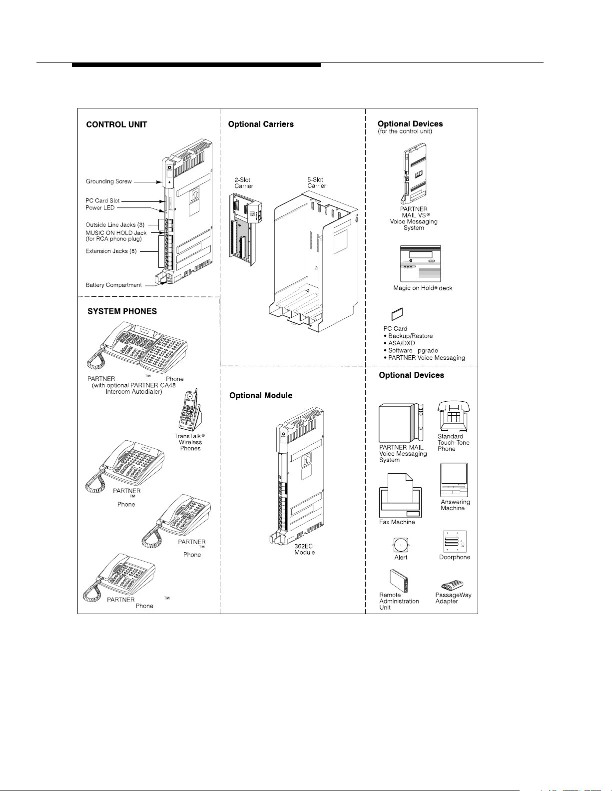
System Components
System Components
Modular hardware design makes the system easy to install and expand. The basic
system consists of a PARTNER Endeavor processor module, which supports
three lines and eight extensions. Using these lines and extensions, you can add
various optional devices and telephones to configure your system to meet your
needs. To expand the system to include more lines and extensions, simply attach
additional modules and a carrier to contain them. The term “control unit” is used to
refer to the stand-alone PARTNER Endeavor 362 processor module (or to the
carrier and the modules it contains), since this is the heart of the system. Figure
1-1 shows an example of system components.
!
WARNING:
There are no customer-serviceable components inside the system modules
or carrier. There are hazardous voltages within that can cause severe or fatal
personal injury. DO NOT OPEN THE MODULES.
1-3
Page 19
Overview
PARTNER Endeavor 362
Processor Module
-
-
E
C
S
MUSIC
ON
HOLD
C
om
bo
C
ombo
-
-
Endeavor -34
Endeavor -18D
Endeavor -6
Endeavor
-18
Figure 1-1. Sample System Components
3
6
2
C
om
C
om
Expansion
U
(for extension jacks on last 2
ports of Endeavor 362 Processor Module
or 362EC Expansion Module)
E
C
bo
bo
1-4
Page 20

System Components
Configurations
The system can have one of three basic configurations:
■ Stand-alone PARTNER Endeavor 362 processor module. This
configuration does not use a carrier.
■ 2-Slot Carrier, which can hold up to two modules. The PARTNER Endeavor
362 processor module resides in the leftmost slot with either a 362EC
expansion module or PARTNER Mail VS (PMVS) module in the right slot.
■ 5-Slot Carrier, which can hold up to five modules. The PARTNER Endeavor
362 processor module resides in the center slot with four 362EC expansion
modules in the remaining slots or three 362EC expansion modules and one
PARTNER Mail VS module in the last slot.
NOTE:
A PARTNER Endeavor PC Upgrade Card is required.
In either carrier, one and only one of the modules must be a PARTNER Endeavor
362 processor module. The modules slide into the carrier, which channels power
to the system.
System Modules
The following system modules can be installed in your system:
■ PARTNER Endeavor 362 Processor Module provides the software
■ 362EC Expansion Module provides expanded line and extension
intelligence that controls the system’s features. It has jacks for three
outside lines, eight extensions (the top six station ports support only
Enhanced Tip Ring devices and the bottom two ports support both
Enhanced Tip Ring and Tip Ring devices), a Music-On-Hold audio source
and a grounding screw. It also has one PC Card slot, a bicolor red and
green light-emitting diode (LED), and two AAA user-replaceable batteries.
The module also provides support for Caller ID information on system
display phones. The system requires one PARTNER Endeavor 362
processor module.
capability. It has jacks for three outside lines and eight extensions (again,
Tip Ring devices are only supported on the bottom two ports). By using
four 362EC expansion modules, you can have a maximum of 40 extensions
with 15 lines (one PARTNER Endeavor 362 processor module and four
362EC expansion modules) .
NOTE:
A 362EC expansion module will work ONLY in conjunction with a PARTNER
Endeavor 362 processor module.
To get Caller ID, first you must subscribe to the service from your local phone
company (if it is available) on a per-line basis, then connect those lines associated
1-5
Page 21

Overview
with Caller ID to the line jacks. Any users with system display phones who receive
calls on Caller ID lines will get Caller ID. For more information, see “Caller ID” in
Chapter 5.
If you want message-waiting capability on standard phones that are equipped with
LED-compatible message-waiting lights, you must connect those phones to the
bottom two extension jacks on a PARTNER Endeavor 362 processor module or
362EC expansion module. Standard phones can be used to make calls when
plugged into any port of the PARTNER Endeavor 362 processor module or 362EC
expansion module. However, standard phones will ring only when plugged into the
Tip Ring ports, which are the bottom two ports.
With the exception of headphones, auxiliary equipment works only on Tip Ring
ports (headphones do not require a ring and can therefore be plugged into any
port). The top six station ports support only Enhanced Tip Ring devices and the
bottom two ports support both Enhanced Tip Ring and Tip Ring devices.
Table 1-1. Summary of Module Capacities
Module Lines Extensions
362 3 8
362EC 3 8
NOTE:
When using a PARTNER MAIL VS Module with the PARTNER Endeavor System,
extension numbering is done dynamically. That is, when numbering extensions, the
module counts as six extensions. However, it is recommended that the PARTNER MAIL
VS module be placed in the last slot of a 2-Slot or 5-Slot Carrier.
System Batteries
The system uses two user-replaceable AAA-size standard alkaline batteries in the
PARTNER Endeavor 362 processor module to ensure that the system
programming and telephone programming settings are not lost in case of a power
failure. See Chapter 6, ‘‘Troubleshooting’’ for instructions for replacing the
batteries.
PC Card Slot
The PAR TNER Endeavor 362 processor module has one PCMCIA (Personal
Computer Memory Card International Association) interface slot (hereafter
referred to as PC Card slot). You can buy the following PC Cards to use in this
slot:
1-6
■ Backup and Restore PC Card
■ PARTNER Endeavor PC Upgrade Card—To upgrade from 2-Slot to
5-Slot system. This must be a PARTNER Endeavor Upgrade Card for use
on a PARTNER Endeavor only.
Page 22

System Components
■ Automatic System Answer/Direct Extension Dial PC Card
■ PARTNER Voice Messaging PC Card
For information on installing PC Cards, see
Instructions
.
PARTNER PC Card Installation
System Capacity
The PARTNER Endeavor release that you have, the carrier you use, and the
combination of modules installed determine the number of available lines and
extensions.
Tab l e 1-2. Configurations fo r Maximum Lines or Maximum Extensions for
PARTNER Endeavor
Configuration Maximum Lines and Extensions
Stand-alone PARTNER Endeavor 362 processor module
(Total = 3 lines, 8 extensions)
2-Slot Carrier One PARTNER Endeavor 362 processor module, one 362EC
expansion module
(Total = 6 lines, 16 extensions)
2-Slot Carrier One PARTNER Endeavor 362 processor module, one PMVS
module
(Total = 3 lines, 8 extensions)
5-Slot Carrier One PARTNER Endeavor 362 processor module, four 362EC
expansion modules
(Total = 15 lines, 40 extensions)
5-Slot Carrier One PARTNER Endeavor 362 processor module, three 362EC
expansion modules, and one PMVS module
(Total = 12 lines, 32 extensions)
System Mode
The system supports two modes of operation. The mode of operation determines
how users access outside lines from their phones:
■
Key Mode.
■
Hybrid Mode.
However, you also can create up to four groups, or
outside lines. When the user accesses a pool to make a call, the system
selects an available line from the pool. Since multiple lines are associated
with the pool, the user does not know which line within the pool is being
used to make the call.
Users access individual outside lines to make and receive calls.
Users can access individual outside lines as in Key mode.
pools,
of multiple
1-7
Page 23

Overview
System mode is determined by the configuration of the processor module. By
default, the system is configured for Key mode. Changing to Hybrid mode requires
modifying the processor module.
Only Lucent Technologies Authorized Personnel
or Authorized Dealers can modify the processor module to accommodate Hybrid
mode.
The mode for your system must be decided upon before installation; and in the
continental U.S., the mode must be registered with the Federal Communications
Commission (FCC) (see ‘‘FCC Registration’’ later in this section).
Key Mode
When the system operates in Key mode, individual outside lines are assigned to
users’ extensions for making and receiving calls. At extensions with system
phones, each individual line (Line 1, Line 2, Line 3, etc.) assigned to the extension
is represented by its own line button. Users can press any of the available line
buttons on their system phones to make outside calls. (Standard phone users
must dial 9 at intercom dial tone to make an outside call since their phones do not
have line buttons.)
Key mode enables users to easily join calls since each line button can be labeled
using a unique line number. For example, if you are requested to join a call on Line
2, you simply press the line button labeled “Line 2.” Key mode also lets users
monitor call activity using the lights next to the line button—everyone who has a
specific line assigned to their extension can tell when an incoming call is ringing
on that line, when a call on that line is on hold, and when that line is in use.
At installation, the system assigns outside lines to the buttons on all system
phones from left to right, starting with the bottom row of buttons. On an extension
basis, you can change which lines are assigned and which buttons are used to
select the lines, if desired.
All extensions in a system configured for Key mode are referred to as
extensions
.
key
Hybrid Mode
Hybrid mode offers users flexibility in accessing outside lines from their phones.
As in Key mode, individual lines can be assigned to system extensions.
pools.
Additionally, multiple outside lines can be grouped together in
main
can have up to four pools, including a
pool is identified by a
Pools are represented on system phones by
buttons give users access to
pool is associated with only
contains most of your company’s outside lines, it is associated with
buttons. This setup allows the user to place a call using one of the main pool
buttons, put that call on hold, and make another call using the second main pool
button. Or, the user can establish a conference call using lines in the main pool.
The main pool and each auxiliary pool can be assigned to an extension, for a
maximum of five pool buttons.
pool access code
multiple
one
pool button. Since the main pool typically
pool and three
—880, 881, 882, and 883 respectively.
pool buttons.
lines from a single button. Each auxiliary
auxiliary
Unlike line buttons, pool
The system
pools. Each
two
pool
1-8
Page 24

System Components
System phone users can press any of the available pool buttons on their phones
or they can enter the pool access code at intercom dial tone to make an outside
call. (Standard phone users must dial 9 or enter the pool access code at intercom
dial tone to access a pool since their phones do not have pool buttons.) After the
user presses a pool button or enters a pool access code, the system selects a free
line from the pool for the user to make the call. A user can access a pool as long
as there is at least one available line in the pool.
A major benefit of Hybrid mode is that it allows users who have system phones
with fewer buttons to have access to multiple outside lines and various types of
pools. You can make efficient use of outside lines by grouping those of a similar
type or function together. For example, you can create an auxiliary pool of WATS
or international lines and assign the pools to different groups of users.
Additionally, individual lines can be assigned to a manager’s extension so that he
or she always has access to an outside line.
In Hybrid mode, extension 10
always
operates like an extension in Key mode. This
means that every outside line in the system is associated with a specific line
button at extension 10.
All other extensions can be set up with access to only lines, only pools, or a
combination of lines and pools:
■ Those extensions that have pool buttons, even if they also have individual
line buttons, are called
■ Those extensions that have only line buttons (including extension 10) are
key extensions.
called
pooled extensions.
Key extensions cannot access pools.
If your system is configured for Hybrid mode, keep in mind:
■ A line can be assigned to only one pool.
■ Individual extensions can have restricted access to specific pools.
■ Individual lines can be assigned to an extension with pool buttons as long
as the lines are not part of any pool.
At installation, the system assigns all outside lines to the main pool and assigns
the main pool to the two leftmost buttons on the bottom row of all system phones,
except extension 10. If desired, you can remove some of the lines from the main
pool and create auxiliary pools. Then you can assign pools and/or individual lines
on a per extension basis.
FCC Registration
In the continental U.S., your system’s mode of operation must be registered with
the FCC as either KF (Key Function) for Key or MF (Multifunction) for Hybrid. If the
system is registered as KF, no outside lines can be pooled; if the system is
registered as MF, lines can be pooled and individual lines also can be assigned
directly to line buttons.
1-9
Page 25

Overview
Telephones
System Telephones
This guide refers to Lucent Technologies telephones specifically designed to work
with the system as system phones. These include the PARTNER Endeavor-34D,
PARTNER Endeavor-18D, PARTNER Endeavor-18, and PARTNER Endeavor-6
telephones. You can also use the Trans Talk© 9000-series wireless phones,
including MDW 9000, MDW 9010, MDW 9030P and MDW 9031P Pocketphone,
although they are not discussed in this guide. For information about a TransTalk
9000-series phone, refer to the documentation that comes with the phone.
System phones have several buttons in common: volume control buttons, and the
f, C, A, h,! and S buttons. In addition, each phone has
programmable buttons
numbers, outside phone numbers, or system features. Outside lines and pools, as
well as some system features, require buttons with status lights. Programmable
buttons without lines or pools assigned to them can be programmed with numbers
or features, so you can use the feature or dial the number with one touch. The
number in each PARTNER Endeavor-model name indicates the number of
buttons with status lights.
that can be used for outside lines, pools, extension
If the PARTNER Endeavor-model phone has a display, indicated by a “D” in the
model name, users receive messages and prompts when making calls and when
programming. PARTNER Endeavor-model phones have a 16-character display .
(More information about the display is provided in Chapter 5.) A system display
phone is
Valid system extensions are 10 – 49. When using a PARTNER MAIL VS Module
with the PARTNER Endeavor System, extension numbering is done dynamically.
That is, when numbering extensions, the module counts as six extensions.
Table 1-3 summarizes PARTNER Endeavor-model system phone features.
required
for system programming.
1-10
Page 26

System Components
Table 1-3. PARTNER Endeavor-Model System Phones
34D 18D 18 6
Total Number of
32 16 16 4
Programmable
Buttons with Status
Lights
Total Number of
4400
Programmable
Buttons without
Status Lights
Key Mode Button
32 16 16 4
Capacity (Number
of Programmable
Buttons with Status
Lights)
Hybrid Mode Pool
Button Capacity
1
5554
Line Capacity 15 15 15 4
Intercom Buttons 2 2 2 2
Display
2
✔✔——
Speakerphone ✔✔✔✔
1. The main pool uses two buttons.
2. PARTNER Endeavor-model phones have a 16-character display.
1-11
Page 27

Overview
Intercom Autodialers
PARTNER Endeavor-model system phones support the PARTNER-CA48 Call
Assistant Intercom Autodialer at extensions 10 and 11. The autodialer provides
Auto Dial buttons for all of the extensions in your system. The status lights next to
each button also indicate calling activity at that extension. Users can program the
Auto Dial buttons for either intercom ringing, voice signaling, or manual signaling.
(Note that each user can have only one Auto Dial button—either on the system
phone or on the autodialer—for another extension in the system.) The Auto Dial
buttons allow the user to dial, signal, or transfer calls to system extensions with
one touch. For more information about Auto Dial buttons, see “Auto Dialing” in
Chapter 5.
Standard Telephones
You can also use industry-standard single-line rotary or touch-tone telephones,
including feature phones with built-in feature buttons and lights, with the system.
This guide refers to such telephones as
Technologies-certified standard phones are recommended.
standard phones
. Lucent
NOTE:
Standard phones can be used to make calls when plugged into any port of
the PARTNER Endeavor 362 processor or 362EC expansion module.
However, standard phones will ring only when plugged into the Tip Ring
ports, which are the bottom two ports.
The following Lucent Technologies phones can make use of the system’s
message-waiting capability:
■ 2500 YMGL Single-Line Analog Telephone Set
■ 8101 Analog Telephone
■ 8101M Analog Tele pho ne
■ 8102 Analog Telephone
■ 8110 Analog Telephone
■ 7102 Plus Analog Voice Terminal
(This model is recommended.)
Check with your local Lucent Technologies Representative or local Authorized
Dealer to find out whether other standard phones with message-waiting lights will
work.
NOTE:
For message waiting capability, you must connect standard phones with
LED-compatible message-waiting lights to a PAR TNER Endeavor 362
processor module. This message-waiting capability does not work with
standard phones with neon-type message-waiting lights.
1-12
Page 28

Auxiliary Equip men t
Enhanced Tip Ring Ports
There are eight Enhanced Tip Ring ports per processor module and 362EC
expansion module. The top six station ports support only Enhanced Tip Ring
devices and the bottom two ports support both Enhanced Tip Ring and Tip Ring
devices. Connect headsets and other adjunct equipment that do not require
incoming ringing to any port or through the AUX jack on a PARTNER Endeavor
telephone.
NOTE:
Doorphones should not be connected to an Enhanced Tip Ring only port
since doorphones rely on receiving a forward disconnect signal to
disconnect a call. If a Tip Ring device is connected to an Enhanced Tip Ring
only port, a forward disconnect signal is not sent and ringing is not heard at
that port.
Auxiliary Equipment
You can connect many types of telecommunications devices to your system
without expensive adapters or additional phone lines—for example, answering
machines, credit card scanners, and fax machines. Many industry-standard,
single-line devices will wor k with the system regardless of the manufacturer.
For more information, refer to the list in Chapter 4 or contact your Lucent
Technologies Representative or local Authorized Dealer. Also, see Chapter 4 for
advice on setting up auxiliary equipment to work effectively with the system.
Requirements
An industry-standard device must meet the following conditions:
■ It must be non-proprietary. That is, it cannot be made specifically for use on
a particular telephone system. (For example, you cannot connect a Lucent
Technologies MERLIN LEGEND® Communication System phone,
because it is specifically designed for use on a MERLIN LEGEND
Communication Syst em.)
■ Its Ringer Equivalence Number (REN
REN is shown on a label on the device, usually on the bottom.)
■ You can connect a standard two-line device to the system, but for best
results it should be installed and used as if it were a single-line device.
1. REN is a measure of the power it takes to ring a phone. The ty pical home phone line supports
4.0–5.0 RENs; each extension jack in your system handles up to 2.0 RENs.
1
) cannot be greater than 2.0. (The
1-13
Page 29

Overview
Connecting Standard Devices
Y ou can connect a standard device so that it is on an extension by itself, or so that
it shares an extension with another piece of equipment (either another standard
device or a system phone) as long as the REN of the two devices together does
not exceed 2.0. (System phones have 0.0 REN.) For example, you can connect a
standard phone and an answering machine to the same extension. An extension
with two devices connected to it is called a
connect two system phones on one extension. The
Installation
guide provides installation instructions.
NOTE:
Standard phones can be used to make calls when plugged into any port of
the PARTNER Endeavor 362 processor or 362EC expansion module.
However, standard phones will ring only when plugged into the Tip Ring
ports, which are the bottom two ports.
combination extension
PARTNER Endeavor
. You cannot
1-14
Page 30

Programming
Overview
After the system hardware is installed, you can customize the system and
individual telephones. This chapter explains how to use
accomplish that.
There are two types of programming:
■
System Programming
needs of your business. When the system is first installed, it uses factory
settings that reflect the most commonly used options. You can change
system settings as needed.
programming
allows you to customize the system to meet the
to
You can perform System Programming from extension 10 or 11. Because
an extension cannot be in programming mode and handle calls at the same
time, consider using extension 11 for programming. Doing so gives you the
ability to program without disrupting call handling by the receptionist at
extension 10.
■
Telephone Programming
individual users’ needs. Individual telephones can be programmed from
extension 10 or 11
extension using a system phone
A system display phone is
Programming. If you have any 34-button phones in the system, you must use a
34-button display phone to program since an 18-button phone
program a 34-button phone.
The system permits programming from a remote location using a Remote
Administration Unit—see ‘‘Remote Programming’’ on page 2-22.
This chapter provides general information about programming procedures. When
a specific feature name is used, it is printed in bold type. For detailed descriptions
and step-by-step instructions, refer to that name in Chapter 5. (A Programming
Quick Reference
is provided at the end of this guide.)
(Centralized Telephone Programming),
allows telephones to be customized to meet
(Extension Programming)
required
for System and Centralized Telephone
cannot
or from a user’s
.
be used to
2-1
Page 31

Programming
Hardware Considerations
Programming procedures use line and extension numbers. The line number
represents the line jack on a PARTNER Endeavor 362 processor or 362EC
expansion module to which the outside line is connected. Similarly, the extension
number represents the extension jack on a 362EC expansion module or a
PARTNER Endeavor 362 processor module to which the system phone or
standard device is connected.
For each 362EC or Endeavor processor module, the system assigns three lines
and eight extensions. The system numbers lines and extensions consecutively
from left to right in a 2-Slot Carrier, beginning with the PARTNER Endeavor 362
processor module in the leftmost slot; in a 5-Slot carrier, the numbering also begins
with the PARTNER Endeavor 362 processor module (in the center slot), and then
moves to the
left-most
Figure 2-1 shows the numbering scheme for a PARTNER Endeavor stand-alone
configuration, for a 2-Slot Carrier, and for a 5-Slot Carrier.
module and continues consecutively from left to right.
Stand-Alone
Processor
Module
ECS
Proc.
P F T
1
2
3
MUSIC
ON
HOLD
P F T
10
11
12
13
14
15
COMBO
16
COMBO
17
Line
Jacks
Extension
Jacks
2-Slot Carrier
Module
10
11
12
13
14
15
16
17
P F T
1
2
3
P F T
COMBO
COMBO
ECS
Proc.
MUSIC
ON
HOLD
362EC
Module
362EC
Module
4
5
6
18
19
20
21
22
23
COMBO
24
COMBO
25
Processor
Line
Jacks
Extension
Jacks
5-Slot Carrier
362EC
Modules
362EC
Module
4
5
6
18
19
20
21
22
23
24
COMBO
25
Processor
Module
362EC
Module
7
8
9
26
27
28
29
30
31
COMBOCOMBO
32
COMBO
33
362EC
Modules
362EC
362EC
ECS
Proc.
P F T
1
2
3
MUSIC
ON
HOLD
P F T
10
11
12
13
14
15
COMBO
16
COMBO
17
Module
10
11
12
34
35
36
37
38
39
COMBO COMBO
40
COMBO
41
13
14
15
42
43
44
45
46
47
48
49
Module
COMBO
Line
Jacks
Extension
Jacks
Figure 2-1. PARTNER Endeavor Stand-Alone, 2-Slot, and 5-Slot Systems Configured for
Maximum Lines (3, 6, 15) and Maximum Extensions (8, 16, or 40)
2-2
Page 32

Initial System Setup
Initial System Setup
After the control unit is installed, you set up the system using a combination of
and
system
Programming procedures are identified by a code (# and three digits); Telephone
Programming procedures are identified by the feature name only.
telephone programming procedures. In this guide, System
Use the
provide an
System Planner
overview
explains how to use the specific procedures. Other programming procedures are
optional, but are strongly recommended to make the most of your investment.
(See ‘‘Sys tem Programming Options’’ on page 2-10 and ‘‘Telephone
Programming Options’’ on page 2-22 for details.)
Setting the System Clock
After supplying power to the control unit, use the following procedures:
■ System Date (#101) to set the month and day.
■ System Day (#102) to set the day of the week.
■ System Time (#103) to set the hour and minutes.
Assigning Lines
Key Extensions
Use the procedures described in this section to assign individual lines to pooled
extensions or assign lines to key extensions. (In Key mode, all extensions are Key
extensions; in Hybrid mode, extension 10 and any extensions set to Key using
Line Access Mode (#313) are key extensions.)
as a guide when programming. The following sections
of the procedures you use for initial system setup. Chapter 5
only
For initial setup
, use Number of Lines (#104) to specify the number of lines
that will be assigned to all system extensions. Then use the following procedures
as needed:
■ Dial Mode (#201) to identify any rotary lines (the default for all lines is
“touch-tone”).
■ Line Assignment (#301) to assign lines to specific extensions (if the line
was not assigned using the Number of Lines procedure), to remove lines
from some extensions, or to change the button used to pick up a line at a
specific extension.
■ Line Access Restriction (#302) to prevent an extension from receiving
and/or
making outside calls on specific lines.
2-3
Page 33

Programming
■ Line Ringing (Centralized Telephone Programming) to specify when a line
will start ringing at each extension that has the line. For additional
information about line ringing options, see ‘‘Programming a
Receptionist’s Extension’’ on page 2-23.
■ Automatic Line Selection (Centralized Telephone Programming) to
specify the order in which the system selects an available line (intercom or
outside), when a user at the extension lifts the handset or presses
make a call without first selecting a specific line button.
For extensions with standard phones, set Automatic Line Selection to
intercom first. This enables standard phones to access system features,
including intercom calling. When users lift the handsets on standard
phones, they hear intercom dial tone. To access an outside line, they must
dial
Pooled Extensions
Use the procedures described in this section if your system is configured for
Hybrid mode to change the assignment of lines in pools and to assign auxiliary
pools to or remove the main pool from pooled extensions. If a pooled extension
also has an individual line, refer to ‘‘Key Extensions’’ to assign that individual
line.
S to
9.
For initial setup only, use Number of Lines (#104) to specify the number of lines
that will be assigned to the main pool. Then use the following procedures as
needed:
■ Dial Mode (#201) to identify any rotary lines (the default for all lines is
“touch-tone”).
■ Pool Line Assignment (#207) to remove lines from the main pool and
assign lines to auxiliary pools.
■ Line Access Mode (#313) to change a specific extension’s operation from
Pooled to Key. Refer to ‘‘Key Extensions’’ to assign lines to those
extensions.
■ Pool Extension Assignment (#314) to remove the main pool, assign
auxiliary pools, or change the location of the button used to select an
auxiliary pool at specific extensions. (The location of the two main pool
buttons cannot be changed.)
■ Pool Access Restriction (#315) to prevent an extension from receiving
and/or making outside calls on all lines in specific pools.
■ Line Ringing (Centralized Telephone Programming) to specify when a line
or pool will start ringing at each extension that has the line or pool. By
default, lines are set to Immediate Ring and pools are set to No Ring. For
additional information on line ringing options, see ‘‘Programming a
Receptionist’s Extension’’ on page 2-23.
■ Automatic Line Selection (Centralized Telephone Programming) to
specify the order in which the system selects an available line or pool,
when a user at the extension lifts the handset or presses
S to make a
call.
2-4
Page 34

Initial System Setup
For extensions with standard phones, set Automatic Line Selection to
intercom first. This enables standard phones to access equipment features,
including intercom calling. When users lift the handsets on standard
phones, they hear intercom dial tone. To access a pool, they can dial the
pool access code 880, 881, 882, or 883 or dial 9 to access the first
available line or pool in the sequence.
Customizi ng Extension s
In addition to line or pool assignments, the following procedures can be used to
customize an extension:
■ Line Coverage Extension (#208) to identify an extension as the “owner”
of a specific outside line. A user at the extension can activate Call
Coverage or VMS Cover for the specified line. Use Call Coverage Rings
(#116) to specify the number of times a call should ring at the owner’s
extension before it is sent to the covering extension or VMS Cover Rings
(#117) to specify the number of times a call should ring at the owner’s
extension before it is sent to the owner’s voice mailbox.
■ Display Language (#303) to specify the language (English, French, or
Spanish) for messages that appear on a system display phone.
■ Automatic Extension Privacy (#304) t o prevent other extensions with the
same line from joining a call at the extension. This feature is also useful for
extensions connected to a modem, fax, or any device whose function can
be disrupted by someone trying to join it.
■ Call Waiting (#316) to identify standard phone extensions that can receive
the system (not the local telephone company) call-waiting tone for a
second incoming call when active on a call.
■ Outgoing Call Restriction (#401) to prevent the extension from making
all
certain types of outgoing calls (on
■ Disallowed List Assignments (#405) to assign one or more Disallowed
system lines).
Phone Number Lists to the extension. Use Disallowed Phone Number
Lists (#404) to create the lists of outside numbers that extensions
cannot
dial.
■ Allowed List Assignments (#408) to assign one or more Allowed Phone
Number Lists to the extension. Use Allowed Phone Number Lists (#407)
to create the lists of outside numbers that otherwise-restricted extensions
can
dial.
■ Pickup Group Extensions (#501), Calling Group Extensions (#502),
Night Service Group Extensions (#504), and Hunt Group Extensions
(#505) to place the extension in any of these groups. See ‘‘Setting Up
Groups of Extensions’’ on page 2-14 for more information.
2-5
Page 35

Programming
Copy Settings
The recommended way to set up your system is to program one extension for
each type of phone in the system, then use Copy Settings (#399) to program
other phones of the same type. For example, you can program one PARTNER
Endeavor-18D phone and then copy its settings to any other extensions that have
PARTNER Endeavor-18D or PARTNER Endeavor-18 phones. See ‘‘Copy
Settings (#399)’’ on page 5-65 for a list of the programmed settings that are
copied.
■ Fax Machine Extensions (#601), Doorphone Extension (#604 and
#605), Doorphone Alert Extensions (#606), AA Extensions (#607),
External Hotline (#311), or Hotline (#603) to identify the extension as one
of these equipment types.
NOTE:
With the exception of headphones, auxiliary equipment works only on Tip
Ring ports (the bottom two ports of the PARTNER Endeavor 362 processor
module or 362EC expansion module). Because headphones do not require
a ring, they can be plugged into any port.
■ ‘‘Setting Up Auxiliar y Equipment’’ on page 2-14 provides an overview of
the procedures you use for setting up devices such as voice messaging
systems. Also , Chapter 4 provides detailed information and example
applications for auxiliary equipment.
Changing Settings after Installation
As your business grows or changes, you will probably need to change the way
your system was originally programmed. This section provides some examples
and lists the procedures you would use to change settings after installation. For
specific details on a procedure, refer to the procedure name in Chapter 5.
■ Automatic System Answer Button (#111)
■ Automatic System Answer Delay (#110)
■ Automatic System Answer Lines (#204)
■ Automatic System Answer Mode (#121)
■ Automatic System Answer Record/Playback (I891)
■ Call Coverage (F20, XX, XX)
■ Call Coverage Rings (#110)
■ Direct Extension Dial Button (#113)
■ Direct Extension Dial Delay (#112)
■ Direct Extension Dial Lines (#205)
■ Direct Extension Dial Record/Playback (I892)
■ Pool Access Restriction (#315)
2-6
Page 36

Changing Settings after Installation
■ Pool Extension Assignment (#314)
■ Pool Line Assignment (#207)
■ PARTNER Voice Messaging PC Card
For more information about setting these features, see Chapter 5, ‘‘Feature
Reference.’’
For more information on using the PARTNER Voice Messaging PC card, see
PARTNER Voice Messaging PC Card Installation, Programming and Use.
Changing the System Clock
You may need to change the system clock for daylight saving time, after a
prolonged power failure, or after a system reset. Use System Date (#101),
System Day (#102), and System Time (#103) to set the current date, day, and
time.
Adding New Lines
Key Extensions
Use this section to add individual lines to pooled extensions or to add new lines to
key extensions (all extensions in Key mode; in Hybrid mode, extension 10 and any
extensions set to Key using Line Access Mode (#301) are key extensions.)
If you add an outside line to your system, you may need to adjust some line
settings. In particular, use Dial Mode (#201) if the new line is a rotary line, Line
Assignment (#301) to assign the line to specific extensions, Line Ringing
(Centralized Telephone Programming) to specify when the line will start ringing at
each extension that has the line, and Line Access Restriction (#302) to limit an
extension’s access to the line. Additionally, the system automatically assigns the
new line as the last line in the Automatic Line Selection sequence. If you want to
change the order, use Automatic Line Selection (Centralized Telephone
Programming).
IMPORTANT:
not
Do
setup, because it changes Line Assignment (#301), Line Access Restriction
(#302), Automatic Line Selection, and Line Ringing for existing lines back to
factory settings. To add a new line without affecting other settings, use Line
Assignment (#301).
Pooled Extensions
use Number of Lines (#104) if you add lines to the system
after
initial
Use this section to add new lines to existing pools if your system is configured for
Hybrid mode. To assign a new line to a pooled extension as an individual line,
follow the procedures in “Key Extensions.”
2-7
Page 37

Programming
If you add an outside line to your system for use in an existing pool, use Dial
Mode (#201) if the new line is a rotary line and Pool Line Assignment (#207) t o
add the line to an existing pool.
IMPORTANT:
Do
not
use Number of Lines (#104) if you add lines to the system after
setup, because it changes Pool Line Assignment (#207), Pool Extension
Assignment (#314), Pool Access Restriction (#315), Automatic Line
Selection, and Line Ringing for existing pools back to factory settings.
Additionally, it changes Line Assignment (#301), Line Access Restriction
(#302), Automatic Line Selection, and Line Ringing for individual lines back to
factory settings. To change pool assignments without affecting other settings, use
Pool Line Assignment (#207) and Pool Extension Assignment (#314).
Adding New Pools
Use this section if your system is configured for Hybrid mode to create new pools.
If you add outside lines to your system for use in a new pool, use Dial Mode
(#201) if the new lines are rotary lines, Pool Line Assignment (#207) to assign
lines to the new pool, Pool Extension Assignment (#314) to assign the new pool
to specific extensions, Line Ringing (Centralized Telephone Programming) to
specify when the new pool will start ringing at each extension that has the pool,
and Pool Access Restriction (#315) to limit an extension’s access to all the lines
in the new pool. Also use Automatic Line Selection (Centralized Telephone
Programming) to add the new pool to the extension’s Automatic Line Selection
sequence.
initial
Adding New Extensions
If you add an extension to your system, you can probably use Copy Settings
(#399) to copy the settings of an existing extension. If you wish to further adjust a
new extension’s settings, see ‘‘Customizing Extensions’’ on page 2-5.
Swapping Extensions
If a user changes location, but wants to keep the same extension number, you can
make the change easily by changing the connection at the control unit.
For example, if the users at extensions 29 and 32 switch offices, you can
disconnect the modular plugs from those extension jacks in the control unit. Then
reconnect the plug from 32 into extension jack 29 and the plug from 29 into
extension jack 32. Now the users can take their respective phones to their new
locations, keep the same extension numbers, and retain the phones’ programmed
settings.
2-8
Page 38

Changing Settings to Support PBX or Centrex Services
Changing Settings to Support
PBX or Centrex Services
This section applies only if you use PBX or Centrex services with your system. If it
does not apply, go to the next section, “System Programming Options.”
■ PBX services are provided by a private telephone switch.
■ Centrex services are provided by your local telephone company from a
Central Office (CO) outside your premises. These services include the
Centrex lines connected to your control unit modules and some set of
features—such as hold, conference, or transfer—that are available on
those lines. Centrex services may be offered in your area under a different
name. For specific Centrex features to be available to you, your company
must subscribe to those features. For specific information about using
Centrex, see the Centrex documentation provided by your local telephone
company.
Some of the issues you should consider when setting up your system to work
effectively behind a PBX or Centrex system are discussed below. Chapter 5
explains how to use the programming procedures discussed here.
Recall Setting
To set up your equipment to work properly with a PBX or Centrex system, first set
Recall Timer Duration (#107) to match the setting used by your PBX or Centrex
system (usually 800 msec, or “32”). This setting affects the length of a Recall
signal sent by the control unit to access PBX or Centrex services.
Dialing Restrictions
Outgoing Call Restriction (#401) is an equipment restriction intended to limit an
extension’s dialing to “inside calls only” (using the
phones) or to “inside and local calls only” (allowing calls within the PBX or Centrex
system and local calls outside the PBX or Centrex system). However, if users in
your system use a dial-out code (9 on most PBX or Centrex systems) before
dialing numbers outside the PBX or Centrex system, the equipment will not be
able to prevent toll calls for extensions restricted to “inside and local calls only”
[unless you use Disallowed Phone Number Lists (#404) to prevent dialing to
specific classes of numbers].
If your PBX or Centrex system includes dialing restrictions, use those instead of
the equipment restrictions. If you have PBX or Centrex dialing restrictions on a line
and also program equipment restrictions, both the PBX or Centrex system and
equipment restrictions apply. However, equipment dialing permissions will not
override PBX or Centrex system restrictions.
i buttons on system
2-9
Page 39

Programming
Speed Dial and Auto Dial Numbers
When you program numbers outside the PBX or Centrex system as Speed Dial
and Auto Dial numbers, include the PBX or Centrex system dial-out code “9” on
most systems), followed by one or more pauses, in the stored number.
System Programming Options
This section discusses programming options that involve multiple procedures
(such as dialing restrictions and auxiliary equipment settings), as well as features
that can be used throughout your system (such as Speed Dialing). You can use a
combination of programming procedures to set up your system to operate most
efficiently, taking into account your company’s telephone service, personnel, and
equipment, as well as the special needs of particular departments. This section
lists the procedures you can use; for details on using a particular procedure, refer
to the procedure name in Chapter 5.
Speed Dialing
You can program up to 100 frequently dialed phone numbers—such as numbers
for suppliers, repair services, customers—so that
four
them by pressing
three-digit code. These are called
buttons: f (or # on a standard phone) plus a
Dialing Restrictions and Permissions
The system has several procedures for restricting telephone use, and several for
overriding those restrictions. You can use any combination of these procedures to
design a system that meets your needs.
When a user makes a call, the system checks the number dialed against all of the
dialing that apply to the extension making the call. When the number dialed
passes a restriction, the system goes to the next restriction, if necessary. If Star
Code Dial Delay (#410) is active, star codes are also checked against the
restrictions. (Star codes, typically dialed before an outgoing call, provide special
services from the local telephone company Central Office (CO); for example,
6 7 enables a dialer to block the sending of Caller ID information to the called
party.) When a user dials a star code, the system checks it against the dialing
restrictions to determine whether the code is allowed. If the code is allowed, the
system resets its checking procedure and checks the remaining digits that the
user dialed to make sure the call is permitted. When a number violates a
restriction, the call is stopped and the user hears a reorder tone (fast busy signal).
all users in the system
System Speed Dial Numbers.
can dial
*
2-10
Page 40

System Programming Optio ns
IMPORTANT:
While procedures that restrict dialing are very effective, absolute protection
against misuse cannot be guaranteed. System phones provide more protection
than standard phones. Therefore, it is strongly recommended that you install
system phones where restricting phone use is important.
Locking an Extension
The system offers a Station Lock feature that lets users enter a four-digit code on
their telephone dialpad to lock their extensions. This helps prevent other users
from making outside calls at those extensions.
Restrictin g Access to Outside Lines or Pools
A user can access a line or pool either by lifting the handset, pressing the line or
pool button on the phone, or dialing the Direct Line Pickup feature code or a pool
access code. If you do not want a user to access a specific outside line or pool,
you can use Line Access Restriction (#302) or Pool Access Restriction (#315)
to control an extension’s access to a certain line or pool (whether the line or pool
is assigned to the extension or not). Table 2-1 provides examples of settings that
can be used to restrict an extension’s access to specific outside lines or pools.
2-11
Page 41

Programming
Table 2-1. Settings that Restrict an Extension’s Access to a Specific Line
Type of Restrictions or
Permissions for the
Extension
Can receive and place
intercom (inside) calls only
Cannot use a specific
outside line or pool
Can only monitor call
Setting for Line
Assignment (#301) and Pool
Extension Assignment (#314)
All outside lines and pools
“not assigned”
1
Outside line or pool “not
assigned”
1
Setting for Line Access
Restriction (#302) an d Pool
Access Restriction (#315)
“No access” for all lines and
pools
“No access” for that line or
pool
Outside line “assigned” “No access” for that line
activity and pick up held
calls on a specific line
Can only receive calls on a
specific line or pool
Can only place outgoing
calls on a specific line
1. If a line or pool is not assigned to the extension, a user can use Direct Line Pickup to
access the line or dial the pool access code to access a line in the pool. Emergency
numbers, Marked System Speed Dial numbers, Allowed Phone numbers, and numbers
dialed using the System Password ov erride all d ialing restric tions if a us er has acces s to an
outside line or pool to place the call.
Outside line or pool
“assigned”
Outside line or pool may be
“assigned”
1
“Incoming only” for that line
or pool
Outgoing only for that line
or pool
Controlling Calls on Outside Lines
When an extension is allowed access to an outside line or pool, you can use the
following procedures to control calling:
■ Outgoing Call Restriction (#401) defines the type of calls (inside only,
local only, or inside, local, and long-distance) that users can make from all
lines or pools available at an extension. Outgoing Call Restriction Button
(#114) allows the receptionist at extension 10 to quickly change an
extension’s current Outgoing Call Restriction setting.
■ Disallowed Phone Number Lists (#404) creates up to eight lists of
numbers that cannot be dialed. After creating Disallowed Phone Number
Lists, use Disallowed List Assignments (#405) to assign one or more
lists to a specific extension.
■ Night Service with System Password (#403) restricts users at extensions
in the Night Service group from dialing outside phone numbers (except
Emergency numbers and Marked System Speed Dial numbers) unless the
password is entered first.
2-12
Page 42

System Programming Optio ns
Table 2-2 provides examples of settings that can be used to restrict an extension’s dialing
once it gets an outside line or pool.
Table 2-2. Settings that Restrict an Extension’s Dialing Once It Gets an Outside Line or Pool
Type of
Restrictions or
Permissions for
the Extension
Setting for Line
Assignment
(#301) or Pool
Extension
Assignment
(314)
Setting for Line
Access
Restriction
(#302) or Pool
Access
Restriction
Setting for
Outgoing Call
Restriction
(#401)
Setting for
Disallowed
Phone Number
Lists (#404)
1
(#315)
Can place
intercom and
local calls only
(and can
Outside line or
pool may be
“assigned”
2
“No restriction” “Local only” Any local
numbers the
extension
should not dial
answer any
call)
Can place
intercom, local
and longdistance calls
(and can
Outside line or
pool may be
“assigned”
2
“No restriction” “No restriction” Any local and
long-distance
numbers the
extension
should not dial
answer any
call)
1. The Disallowed List then must be assigned to the extension using Disallowed List Assignment
2. If a line or pool i s not assigned to the exten sion, a user can use Direc t Line Pick up to access th e line
.
(#405)
or dial the pool access code to access a line in the pool. Emergency numbers, Marked System
Speed Dial numbers, Allowed Phone numbers, and numbers dialed using the System Password
override all dialing restrictions if a us er has access to an outside line or pool to place the call.
Overridi ng Dialing Restricti ons
The following programming procedures provide ways to override all dialing
restrictions, provided the user has access to an outside line or pool:
■ Emergency Phone Number List (#406) defines a list of up to ten numbers
that can be dialed from any extension. A typical number is 911.
■ Marked System Speed Dial Numbers are specially identified System
Speed Dial numbers, which a user can dial by pressing
standard phone) followed by a three-digit code.
■ System Password (#403) creates a password that can be entered at any
PARTNER Endeavor-model phone to override dialing restrictions for the
duration of a call. The system password should be changed periodically to
prevent unauthorized use and toll fraud.
f (or # on a
2-13
Page 43

Programming
To override all dialing restrictions except Line Access Restriction (#302), pool
Access Restrict ion, and Night Service with System Password (#403), use
Allowed Phone Number Lists (#407) to create up to eight lists of outside
numbers that otherwise-restricted extensions
Assignments (#408) to assign one or more of the lists to an extension.
Setting Up Groups of Extensions
You can set up four types of extension groups:
■ Pickup Group Extensions (#501) assigns extensions to one of four
Pickup Groups. A Pickup Group lets any user in the system answer outside
calls for any extension in that group.
■ Calling Group Extensions (#502) assigns extensions to one of four
Calling Groups. A Calling Group lets users ring or page all extensions in
that group simultaneously or transfer calls into the group.
■ Night Service Group Extensions (#504) assigns extensions to the Night
Service Group. When Night Service is activated at extension 10, calls ring
immediately at Night Service extensions regardless of how they ring at
other times (only the lines assigned to an extension will ring).
■ Hunt Group Extensions (#505) assigns extensions to one of seven Hunt
Groups. (Hunt Group 7 is used exclusively for the voice messaging
system.) A Hunt Group lets users ring or voice signal the first available
(non-busy) extension in that group. If a ringing call is not answered, the
system tries each available extension in turn until the call is answered. If a
voice-signaled call is not answered, the call does not keep hunting. Also
use Group Call Distribution (#206) to assign outside lines to a Hunt
Group if you want outside calls to ring directly into a group.
can
dial. Then use Allowed List
Setting Up Auxiliary Equipment
The following programming procedures help you manage auxiliary equipment.
See Chapter 4 for more information about auxiliary equipment configurations or
refer to Chapter 5 for details on using the procedure:
■ Fax Machine Extensions (#601) identifies extensions to which fax
machines are connected.
■ The music-on-hold feature uses the following procedures:
— Music-On-Hold (#602) activates or deactivates the Music-On-Hold
jack on the PARTNER Endeavor processor module.
— When this jack is activated, an audio source is connected, and Ring
on Transfer (#11 9) is set to “Not Active,” callers hear recorded
music or messages while being transferred.
2-14
Page 44

System Programming Optio ns
— Music-On-Hold Volume (#614) controls the volume at which the
music plays when the Music-On-Hold jack is active. Changes to this
setting affect the many features that use Music-On-Hold:
Background Music, Call Park, Call Waiting, Conference,
Exclusive Hold, Hold, Transfer, and Transfer Return.
— Background Music lets users with system phones (other than the
MDC 9000 or TransTalk 9000-series phon es ) play the re cord ed
material through their phone’s speaker when the phone is not in use.
■ Hotline (#603) identifies internal hotline extensions, so when a person lifts
the handset of the hotline phone, a predetermined
automatically rings. External Hotline (#311) identifies external hotline
extensions, so when a person lifts the handset of the hotline phone, a
predetermined
■ Doorphone Extension (#604 and #605) identifies extensions to which
doorphones are connected. Doorphone Alert Extensions (#606)
identifies extensions that signal when the doorphone button is pressed.
NOTE:
Doorphones should not be connected to an Enhanced Tip Ring only port
since doorphones rely on receiving a forward disconnect signal to
disconnect a call. Connect doorphones to Tip Ring ports, which are the
bottom two ports of any processor or 362EC expansion module.
outside phone number
extension number
is automatically dialed.
■ AA Extensions (#607) identifies an extension to which an auto attendant
is connected. This lets the system notify users with display phones when
they are receiving a call that has been transferred from the auto attendant.
Also, Transfer Return Extension (#306) lets you identify the extension to
which a call transferred by the auto attendant should be routed if the
destination extension does not answer.
■ The voice messaging system uses the following procedures:
— Hunt Group Extensions (#505) assigns the extensions associated
with the voice messaging system hardware to Hunt Group 7—the
VMS Hunt Group.
— Group Call Distribution (#206) assigns lines to the VMS Hunt
Group so calls can ring directly into the voice messaging system
and receive Automated Attendant Service.
— Line Coverage Extension (#208) identifies an extension as the
owner of a specific outside line so calls on that line can ring directly
into the owner’s voice mailbox when either Automatic VMS Cover
(#310) or VMS Cover is on at the owner’s extension.
— VMS Hunt Delay (#506) determines when outside calls should be
answered by the Automated Attendant Service of the voice
messaging system. You can set the system for either immediate call
handling or delayed call handling. The setting you select is used for
both day and night operation.
2-15
Page 45

Programming
— VMS Hunt Schedule (#507) determines when outside calls should
ring the VMS Hunt Group (always, day only, or night only) depending
on the status of the Night Service Button (#503) at extension 10.
— Automatic VMS Cover (#310) determines whether or not an
extension’s unanswered intercom and transferred calls and outside
calls on lines assigned ownership are automatically covered by the
voice messaging system.
— VMS Cover Rings (#117) specifies the number of times intercom
and transferred calls or outside calls on lines assigned ownership
ring at extensions before they are sent to the voice messaging
system.
— Transfer Return Extension (#306) identifies the extension to which
a call transferred by the voice messaging system should be routed if
the destination extension does not answer and does not have voice
mail coverage active. (The transfer return extension for the voice
messaging system is typically extension 10.)
NOTE:
If an extension has VMS Cover and Call Coverage active, intercom and
transferred calls and outside calls on lines assigned ownership ring at the
covering extension after the specified number of Call Coverage Rings
(#116). Then:
■ If the covering extension does not answer, the call is routed after the
specified number of VMS Cover Rings (#117) to the voice mailbox of the
extension that activated Call Coverage .
■ If the covering extension has Do Not Disturb active, the call is immediately
routed to the voice mailbox of the extension that activated Call Coverage.
Backup and Restore Features
The PAR TNER Endeavor 362 processor module has one PC Card slot. This slot
functions similarly to a floppy drive on a PC, in that information can be added to
the system or copied from the system using a PC Card inserted into the slot. To
use the optional Backup and Restore features of the system, you must purchase a
Backup/Restore PC Card from Lucent Technologies. Only these Lucent
Technologies PC Cards can be used in the PARTNER Endeavor processor
module. The same PC Card stores both automatic and manual backups
separately. To install a Backup/Restore PC Card, see
Installation Instructions
Backup Programming—Automatic (#123) enables you to specify whether
automatic backups should be performed or not. If you set this feature to “Active,”
your system and telephone programming settings are backed up to the PC Card
automatically at 2:00 a.m. on the first day of each month. The PC Card must be
present in the PC Card slot for the backup to take place.
PARTNER PC Card
.
2-16
Page 46

Using System Programming
Backup Programming—Manual (#124) enables you to initiate a backup of your
system and telephone programming settings whenever you feel that it is
necessary. It is recommended that a backup be performed after any change to the
system or telephone programming.
Restore Programming (#125) copies either the manual or the automatic backup
data stored on a PC Card back to the system, thereby enabling you to restore
settings to their status at the time of the last automatic or manual backup.
Hospitality Features
The following hospitality feature is for special applications, such as the
Bed-and-Breakfast and Hotel/Motel industries. The receptionist at extension 10
optionally can use the Intercom Autodialer to specify an extension.
■ Outgoing Call Restriction Button (#114) lets you program a button on
the system phone at extension 10 to change an extension’s current
Outgoing Call Restriction setting
mode. For example, after a guest’s departure, a hotel manager can change
the No Restriction setting of the guest room phone to “Inside Only” so
outside calls cannot be made from the phone after the guest checks out.
without
entering System Programmi ng
Using System Programming
System Programming changes settings for the system as a whole, or for individual
lines, pools, or extensions. Y ou can also use System Programming to set up
dialing restrictions, define groups, or set up auxiliary equipment. Refer to the
filled-out
that any changes in programming are recorded there.
System Planner
Programming Overlays
System Programming requires a Programming Overlay placed over the dialpad of
the system display phone at extension 10 or 11. Overlays are provided with the
system documentation. Replacements can be ordered from the Lucent
Technologies BCS Publications Center. (See ‘‘Reference Materials’’ under
‘‘Product Ordering Information’’ on page B-3.) Figure 2-2 on page 2-19
illustrates the Programming Overlays for the PARTNER Endeavor-34D and
PARTNER Endeavor-18D phones.
During System Programming, the normal functions of several buttons on the
display phone at extension 10 or 11 change. For example, the left
becomes
Programming Overlay identifies these buttons.
s and the right i button becomes c. The
when you are changing system settings, and be sure
i button
2-17
Page 47

Programming
You use the following special buttons while programming:
■ N and P cycle forward and backward through the
programming procedures. Y ou can use these buttons to select a procedure.
(If a procedure instructs you to press
N P, pressing
these buttons one after the other enables you to repeat the current
programming procedure.)
■ n and p cycle forward and backward through a procedure’s
parameters. A parameter is typically an outside line, a pool, an extension,
or a telephone list entry.
■ D and d cycle forward and backward through the valid
entries. These buttons work only for fixed data, such as a line or extension
number. They do not work for variable data such as date, time, password,
telephone numbers, or doorphone assignments.
■ r returns the current setting to the factory setting. When using Line
Assignment (#301), removes lines from an extension; when using Pool
Extension Assignment (#314), removes pools from an extension.
■ e ends an entry of variable length, such as a telephone number in an
Allowed Phone Number List.
■ s starts the System Programming process.
■ c starts the Centralized Telephone Programming process (to
customize individual telephones centrally from extension 10 or 11).
■ f when followed by 0 0, enters or exits programming mode.
■ w enters a “wildcard” (a character that matches any digit dialed) in
telephone numbers in Allowed Phone Number Lists (#407) and the
Disallowed Phone Number Lists (#404).
2-18
Page 48

Using System Programming
System
Program
Next
Procedure
Prev
Procedure
Central
Tel Program
Feature
Wild
Next
Item
Prev
Item
Next
Data
Prev
Data
Next
Procedure
Prev
Procedure
Remove
Enter
Next
Item
Prev
Item
Message
Next
Data
Prev
Data
Remove
Enter
System
Program
Feature
Wild
Central
Tel Program
Message
Figure 2-2. Programming Overlays for PARTNER Endeavor-Model 18D and 34D Phones
2-19
Page 49

Programming
Button Locations
When programming from a PARTNER Endeavor model phone at extension 10 or
11, keep in mind that the button you press at the programming extension may be
in a different location on the phone to which the programming applies. Figure 2-3
on page 2-21 shows the relative location of buttons on each PARTNER
Endeavor- model phone.
Programming Mode
1. Place the Programming Overlay over the dialpad of the system display
phone at extension 10 or 11—see ‘‘Programming Overlays’’ on page
2-17 for more information.
2. To enter programming mode, press
on the display:
PROGRAM EXT 10
(If you are programming from extension 11, “11" displays instead of “10.”)
3. Press
4. Press
5. Specify a programming procedure in one of two ways:
s. The following appears on the display:
10 Enter name
This display is for the Extension Name Display feature. When you are
entering System Programming mode, skip it by moving on to Step 4.
s again. The following appears on the display:
SYSTEM PROGRAM
■
Direct Method:
Programming procedures in this guide are identified by a # and a
three-digit code (for example, System Date is #101). This method is
best when you are using only a few procedures during a
programming session and you know the codes.
■
Cycle Method:
N and P to cycle forward and backward
Press
through the programming procedures. This method is best when you
are using multiple procedures during a programming session, or if
you do not know the codes.
Dial the code for that procedure. System
Cycle through the procedures in numerical order.
f 0 0. The following appears
6. To exit programming mode, you can press
off-hook, then place it back in the cradle.
NOTE:
Y ou can talk on the phone while you program. This is useful if you call for support while
programming. However, you must call before you enter programming mode, and you
must use the handset to talk, not the speaker and microphone.
f 0 0 or lift the handset
2-20
Page 50

Using System Programming
QRS T
MN O P
GH
AB C D
Intercom Intercom
Ext.
KLIJ
EF
Message
QR S T
MN O P
IJKL
EFGH
AB CD
Message
Intercom Intercom
Ext.
D
C
B
A
Intercom Intercom
MessageExt.
Figure 2-3. Button Locations on PARTNER Endeavor-Model Phones
2-21
Page 51

Programming
Changing Programming Type
When you are in programming mode, you can move between System
Programming and Centralized Telephone Programming. T o change to Centralized
Telephone Programming when you are in System Programming, press
c. To move back to System Programming when you are in Centralized
Telephone Programming, press
Remote Programming
The system permits programming from a remote location using an auxiliary device
called the Remote Administration Unit (RAU). Remote programming requires the
installation of two RAUs—one at your site and one at the location from which the
programming is to be done. For more information about remote programming, see
PARTNER Communications System Remote Administration Unit Installation
the
and Use
guide.
c then s.
Telephone Programming Opti ons
System telephones are ready to use when they are installed, but they can be
customized to meet the needs of your business and individual users. This
customization is accomplished through
Automatic Line Selection
When a user lifts the telephone’s handset or presses S, the system chooses an
idle line or pool. Automatic Line Selection determines the order in which the
system looks for an idle line or pool. You can set the system to look for lines or
pools in any desired order. For standard phones or for any phone used mainly to
call other extensions, select an inside (intercom) line first.
Extension Name Display
With Extension Name Display, users can assign a name (up to 12 characters
long) to their extension. Then, when those users make an intercom call, group
call, or transfer a call, their name and extension number appears on the display
phone receiving the call. Similarly, users receiving a transfer return call see the
name and extension number of the person assigned to the extension that did not
answer the transferred call.
Line Ringing
Telephone Programming
.
2-22
Line Ringing defines when each outside line or pool rings at a phone. For each
line or pool at an extension, you can specify Immediate Ring, Delayed Ring
(phone rings after a 20-second delay), or No Ring. The factory setting for line
buttons is Immediate ring; the factory setting for pool buttons is No Ring.
Page 52

Telephone Programming Options
Personal Speed Dialing
Personal Speed Dial numbers are outside phone numbers that a user dials by
pressing
f (or # on a standard phone) plus a two-digit code. Unlike System
Speed Dial numbers, which are available to all users in the system, Personal
Speed Dial numbers are available
programmed. Users can store up to 20 Personal Speed Dial numbers.
Programming Telephone Buttons
T elephone buttons without lines or pools assigned to them can be programmed for
system features such as Exclusive Hold or Conference Drop or for telephone
numbers, so you can use the feature or dial the phone number with one touch.
Once programmed, these buttons are called
pressing the button automatically dials the feature code or telephone number.
A user who has a system phone with programmable buttons should consider
programming them with a combination of frequently used features and outside
and intercom telephone numbers.
only
at the extension for which they are
Auto Dial buttons
, because simply
Programming a Receptionist’s Extension
Call Handling Options
If you set up a centralized telephone answering position at extension 10, use the
following settings to customize it:
■
Immediate Call Answering.
Line Assignment (#301) to assign all lines to extension 10. Set Line
Ringing for all lines at extension 10 to Immediate Ring; set the lines
assigned at each user’s extension to Delayed Ring or No Ring.
In Hybrid mode, Immediate Call Answering is the factory setting. (Lines are
assigned as individual line buttons on the phone at extension 10 and all
pool buttons assigned to users’ extensions are set to No Ring.)
■
Backup Call Answering.
when a user does not pick up
10 to Delayed Ring; set the lines or pools assigned at each user’s
extension to Immediate Ring.
■
No Answering.
all, either set Line Ringing for those lines at extension 10 to No Ring or
simply use Line Assignment (#301) to remove those lines from extension
10. In either case, set Line Access Restriction (#302) to No Access for
those lines at extension 10 to prevent the receptionist from using Direct
Line Pickup to access those lines.
If some lines should not be picked up by the receptionist at
If the receptionist should answer
all calls
If the receptionist should answer some lines
, set Line Ringing for those lines at extension
, use
only
2-23
Page 53

Programming
Backup Answering Options
To assist the receptionist in handling calls, consider the following features:
■ Automatic System Answer. Useful during peak calling periods to answer
outside calls while the receptionist is busy on other calls. When activated,
this feature answers incoming calls after a specified number of rings and
plays a customized greeting. This requires an optional ASA/DXD PC card.
For installation instructions, see
Instructions.
(#121) is programmed, the system either:
— Places the call on hold at extension 10 (the light next to the line
button winks green at extension 10 and winks red at all other
extensions that have the line); the outside caller hears MusicOn-Hold, if it is available.
— Continues to ring all extensions that have access to the line (the
green light next to the line button at those extensions flash); the
outside caller hears Music-On-Hold, if it is available.
— Disconnects the call.
PARTNER PC Card Installation
Then, depending on how Automatic System Answer Mode
The first two options provide audible and/or visual indication of incoming
calls waiting to be answered.
The third option is not applicable as a backup answering feature; however,
it is useful for making brief announcements such as temporary closings or
hours of business.
■ Direct Extension Dial. Useful for routing outside callers directly to a
specific extension or Hunt Group. When activated, this feature answers
incoming calls after a specified number of rings and plays a customized
message prompting the caller to dial the digits of the designated extension
or hunt group.
■ Call Forwarding/Call Follow-Me. Useful when a receptionist leaves the
desk for any period of time. Calls can be forwarded to a backup answering
extension.
■ Call Coverage. Useful when users are unable to answer their calls and
want them answered by someone else.
Alternatively, you can install a voice messaging system to provide an automated
backup answering position. Useful when the receptionist is busy on calls, away
from the desk, or at night, the voice messaging system answers incoming calls
after a specified number of rings, plays a customized greeting, requests callers to
enter an extension number, and transfers the caller to the appropriate extension. If
no one answers at the destination extension, the caller can leave a personal
message in that extension’s mailbox.
2-24
Page 54

Telephone Programming Options
Button Programming
The P ARTNER Endeavor-34D phone shown in Figure 2-4 illustrates the following
programmed buttons in addition to some other system features:
■
Extension Numbers.
through 28. The receptionist can use these buttons to dial or transfer calls
to the extensions with one touch. In addition, the lights of these Auto Dial
buttons show the status of the extension, so the receptionist can tell
whether the phone at the extension is idle (
calling the receptionist (
signaling the receptioni st
receptionist transferred a call (
■
Manual Signaling.
MS-Bill) is programmed to signal the target extension. When the button is
pressed, the user at the target extension will hear a tone for as long as the
button is pressed. This feature is typically used by a receptionist to alert the
boss to an important incoming call when the boss is already on a call. The
lights of a Manual Signaling button work like an Auto Dial button to show
the status of the target extension. Additionally, a Manual Signaling button
can be used to place intercom calls. (Manual Signaling applies only to
system phones.) See ‘‘Manual Signaling (F13XX or F13*XX)’’ on page
5-145 for more information.
Auto Dial buttons are programmed for extensions 11
green flash)
(green flutter),
green flutter
no lights on),
, sending coverage calls to or manually
or ringing back after the
).
busy (
red on
A Manual Signaling button (for example, labeled
),
NOTE:
You can have only one button for a target extension per extension. The
button can be programmed as a Manual Signaling button or as an Auto Dial
button for intercom ringing or voice signaling.
■
Fax Management.
A button (for example, labeled Fax-16) is programmed
as a Fax Management button for the fax machine connected to extension
16. With the exception of headphones, auxiliary equipment works only on
Tip Ring ports (the bottom two ports of the PARTNER Endeavor 362
processor or 362EC expansion module). Because headphones do not
require a ring, they can be plugged into any port. The lights next to the
button show what is happening at the fax machine (for example,
indicates that the fax machine is not responding—for example when
flutter
red broken
it is out of paper). (For more information, see ‘‘Using the Fax
Management Feature’’ on page 4-11.)
2-25
Page 55

Programming
Line/
Programmable
Buttons
Any unused
line button is
programmable
Intercom Intercom
Ext.
Message
Figure 2-4. Button Programming for Receptionist’s Phone
Alternatively, an Intercom Autodialer for the extensions the receptionist dials most
frequently can be used. This leaves buttons on the phone free for more features
and phone numbers.
Using Telephone Programming
There are two ways to program a telephone:
from extension 10 or 11(see below) and
own extension (see ‘‘Using Extension Programming’’ on page 2-29).
Telephone Models
Figure 2-5 illustrates a PARTNER Endeavor-18D set up as a key extension and
Figure 2-6 illustrates a PARTNER Endeavor-6 phone set up as a pooled
extension. As you program buttons, mark their functions on the phone’s labeling
sheet (see the examples in Figure 2-5 and Figure 2-6).
NOTE:
A PARTNER Endeavor-6 phone only has four buttons available for lines or
pools. If four lines are assigned, it has no programmable buttons. If the main
pool is assigned, it has two programmable buttons. The MDW 9000 phones
look just like a PARTNER Endeavor-6 phone when you program them
centrally.
Centralized Telephone Programming
Extension Programming
from a user’s
2-26
Page 56

Using Telephone Programming
Message
Any unused
line button is
programmable
Intercom Intercom
Ext.
Figure 2-5. Example of PARTNER Endeavor-18D Phone as a Key Extension
Intercom Intercom
MessageExt.
Figure 2-6. Example of PARTNER Endeavor-6 Phone as a Pooled Extension
Using Centralized Telephone Programming
Use Centralized Telephone Programming to program features or store telephone
numbers for individual extensions from extension 10 or 11. Most features also can
be programmed on a system phone at the user’s extension. Keep in mind the
following exceptions:
■ Automatic Line Selection and Line Ringing always must be programmed
using Centralized Telephone Programming.
■ If a user has a standard phone, Personal Speed Dial Numbers for the
extension can be programmed only by using Centralized Telephone
Programming.
■ If a user has a standard phone or a non-display system phone, Extension
Name Display for the extension can be programmed only by using
Centralized Telephone Programming.
During Centralized Telephone Programming, the display phone at extension 10 or
1 1 takes on the characteristics of the telephone being programmed, including any
System Programming settings and lines assigned to the phone. If you have any
2-27
Page 57

Programming
34-button phones in the system, you must use a 34-button display phone to
program since an 18-button phone
To program a phone from extension 10 or 11, use the following procedure:
cannot
1. Place the Programming Overlay over the dialpad of the system display
phone at extension 10 or 11—see ‘‘Programming Overlays’’ on page
2-17 for more information.
2. To start programming:
be used to program a 34-button phone.
a. Press
b. Press
c. Press
d. Press
3. Dial the extension number of the telephone to be programmed.
f 0 0. The following appears on the display:
PROGRAM EXT 10
(If you are programming from extension 11, “11" displays instead of
“10.”)
s. The following appears on the display:
10 Enter Ext name
This display is for the Extension Name Display feature. When you
are entering Centralized Telephone Programming mode, skip it by
moving on to Step 2c.
s again. The display reads:
SYSTEM PROGRAM
c. The following appears on the display:
CENTRAL TEL PROG
Extension:
The green lights next to buttons on which lines or pools are assigned show
the current Line Ringing settings; remaining buttons can be programmed
with telephone numbers, extension numbers, or system features.
4. At this point, you can:
■ Use Automatic Line Selection to change the order in which the
telephone selects a line or pool when the user picks up the handset.
(If you want to change Automatic Line Selection for an extension,
you must do so immediately after you enter programming mode and
dial the extension number.)
2-28
■ Use Extension Name Display to assign a user’s name to the
extension. See Chapter 5 for the character codes. (Like Automatic
Line Selection, this procedure must be done immediately after you
enter programming mode and dial the extension number. If you want
to change both Automatic Line Selection and Extension Name
Display, first change Automatic Line Selection, then press
c, redial the extension number, then use Extension
Name Display.)
■ Use Line Ringing to change the ringing for an individual line or
pool.
Page 58

Using Telephone Programming
5. Program Personal Speed Dial Numbers, Auto Dial numbers, or system
features as described in Chapter 5.
To erase the current programming from a button, press the button, then
!.
press
6. To change the settings for another extension, press
the new extension number.
7. To exit programming mode, you can press
off-hook, then place it back in the cradle.
Changing Programming Type
When you are in programming mode, you can move between System
Programming and Centralized Telephone Programming. To change to System
Programming when you are in Centralized Telephone Programming, press
c then s. To move back to Centralized Telephone
Programming when you are in System Programming, press
Using Extension Programming
c, then dial
f 0 0, or lift the handset
c.
Users can program features or store numbers on buttons from their own phones
using Extension Programming. Keep in mind the following exceptions:
■ Automatic Line Selection and Line Ringing always must be programmed
using Centralized Telephone Programming.
■ If a user has a standard phone, Personal Speed Dial Numbers for the
extension can be programmed only by using Centralized Telephone
Programming.
■ If a user has a standard phone or a non-display system phone, Extension
Name Display for the extension can be programmed only by using
Centralized Telephone Programming.
To program at the extension, use the following procedure:
1. To start programming, dial
f 0 0.
The green lights next to buttons on which lines or pools are assigned for
the extension show the current Line Ringing settings. Remaining buttons
can be programmed with telephone numbers, extension numbers, or
system features.
2. To assign a name to the extension, press left i, then enter the
character codes. See ‘‘Extension Name Display’’ on page 5-98 for the
codes.
3. Program Personal Speed Dial Numbers, Auto Dial numbers, or sys tem
features as described in Chapter 5.
To erase the current programming from a button, press the button, then
!.
press
4. To exit programming mode, you can press
off-hook, then place it back in the cradle.
f 0 0, or lift the handset
2-29
Page 59

Programming
2-30
Page 60

Learning about Telephones
This chapter explains how system and standard phones work with the system, as
well as, combination extensions where more than one phone or standard device is
installed. In addition, basic call-handling features and dial-code features are listed
at the end of this chapter. See the feature name in Chapter 5 for details about a
specific feature.
System Telephones
PARTNER Endeavor-model phones have several buttons and indicators. The
following pages explain where they are and how they work.
3-1
Page 61
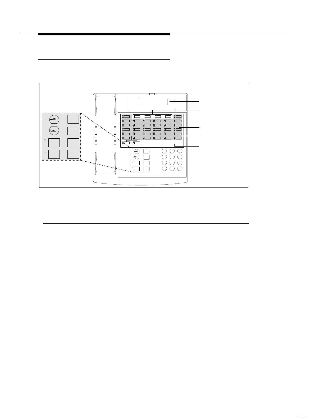
Learning about Telephones
Buttons and Indicators
Feature
+
–
Conf
Mic/
HFAI
Transfr
HoldSpkr
PARTNER Endeavor-34D
Intercom
Mic/
HFAI
Ext.
Feature
+
–
Conf
Transfr
HoldSpkr
Intercom
Display
Programmable Buttons
(4 without lights)
Line/Programmable
(32 with lights)
Buttons
Intercom Buttons (2)
Message
ABC2DEF
31
JKL5MNO
GHI
PQRS
6
4
TUV8WXYZ
9
7
#
0
*
Message Light
Figure 3-1. PARTNER Endeavor-34D Buttons and Indicators
The following buttons and indicators appear on system phones:
Display. (PARTNER Endeavor-34D and PARTNER Endeavor-18D only) Shows date, day, and
time when the phone is idle, number dialed when placing a call, extension number (and name if
programmed) calling you or transferring a call to you, and duration while a call is in progress.
When programming, shows settings, options, and prompts. PARTNER Endeavor-model phones
have a 16-character display.
Line/Programmable Buttons. Used for individual outside lines or (if no line is assigned on a
button) for programming te lephone or e xtension num bers, or oth er system fea tures (suc h as Last
Number Redial). W hen a line is a ssign ed, pre ss t he lin e butt on to ma ke a call on th at spe cific line
(lights show status of line). When a number feature is programmed, press the button to dial the
number or use the feature. PARTNER Endeavor-34D has 36 program mable buttons (32 with
lights and 4 without li ghts); the PARTNER En dea vo r-18D h as 20 p rogra mm ab le b utto ns (16 wi th
lights and 4 without lights); the PARTNER Endeavor-18 has 16 programmable buttons (all with
lights); the PARTNER Endeavor-6 has 4 programmable buttons (all with lights).
Intercom Buttons. Press to m ake (o r answe r) a ca ll to (or fr om) an other e xtens ion in the s ystem.
Feature. Press to change programmed settings or use system features.
Conf. Press to add other parties to your call.
Transfr. Press to pass a call to another extension.
Hold. Press to put a call on hold.
3-2
Page 62

System Telephones
PARTNER Endeavor-18D
Intercom
Feature
+
–
Mic/
Transfr
HFAI
Spkr
PARTNER Endeavor-6
Line/Programmable
Buttons
(4)
Intercom Intercom
Ext.
Feat
+
–
Conf
Transfr
ABC2DEF
JKL5MNO
GHI
4
TUV8WXYZ
PQRS
7
0
*
Message
Spkr
Mic/
HFAI
Hold
31
6
9
#
Intercom Buttons
Message Light
+
–
Feat
Conf
Transfr
(2)
Spkr
Mic/
HFAI
Hold
PARTNER Endeavor-18
Display
Programmable Buttons
(4 without lights)
Line/Programmable Buttons
(16 with lights)
Message
Ext.
Intercom
ABC2DEF
31
JKL5MNO
GHI
Conf
Hold
6
4
TUV8WXYZ
PQRS
9
7
#
0
*
Intercom Buttons
Message Light
Mic/
HFAI
(2)
Feature
+
–
Conf
Transfr
HoldSpkr
Mic/
HFAI
Spkr
Intercom
Intercom
Feature
+
–
Conf
Transfr
Hold
Message
Ext.
ABC2DEF
31
JKL5MNO
GHI
6
4
TUV8WXYZ
PQRS
9
7
#
0
*
Figure 3-2. PARTNER Endeavor-6, PARTNER Endeavor-18D, and PART NER
Endeavor-18 Buttons and Indicators
Spkr. Press to turn on and off the speaker and microphone (if available), so you can dial and
have a conversation without lifting the handset. The light next to this button shows when the
speaker is turned on.
Mic/HFAI. Press to turn the microphone on and off. The light next to this button shows when the
microphone is turned on. Leave on to use Hands-Free Answer on Intercom (HFAI) feature.
Volume Control Buttons. Press - to decrease or + to increase the volume as follows:
■ To adjust ringer volume, press while the phone is idle and the handset is in the cradle.
■ To adjust speaker volume, press while listening to a call through the speaker.
■ To adjust handset volume, press while listening through the handset.
■ To adjust background music vo lume, press while li stening to m usic throug h the phone’ s
speaker .
Lights
Each line or pool button has a green light and a red light. The meaning of these
lights varies, depending on whether the button is used to access an outside line or
pool, is programmed with a system feature, or is programmed for Auto Dialing an
extension number (Intercom Auto Dial button). (Auto Dial buttons for fax
3-3
Page 63

Learning about Telephones
extensions show additional information; these “Fax Management” buttons are
described in Chapter 4. When a phone is in programming mode, the lights show
information about programmed settings; see Chapter 2 for details.)
Table 3-1 shows the meanings of the various light patterns for each possible
button assignment.
Table 3-1. Light Patterns for System Phones
Light Pattern Line Button Pool Button Feature Button
Steady On Line is in use.
Green means
— Green means
feature
1
is on.
you are using
the line; red
means someone
at another
extension is
using the line.
(steady off)
Off
Line is idle (not
—Feature
1
is off. Extension
being used).
Intercom Auto
Dial Button
Red means the
extension
programmed on
the button is busy
(making or
answering a call).
programmed on
the button is idle
(not being used).
(long on, long off)
Flash
Alternating Red/Green
(red on, green on,
Flash
red on, green on)
A call is ringing
on the line.
Green flash
means a call is
ringing at your
extension. Red
flash means a
call is ringing on
the line, but not
at your
extension.
Alternating
green and red
flash appears at
both extensions
in a joined call,
and at any
extension
connected in a
conference call.
— A user is entering
a four-digit code
to lock or unlock
his or her
extension.
Green flash
means someone
at the extension
programmed on
the button is
calling you.
—— —
3-4
Page 64

System Telephones
Table 3-1. Light Patterns for System Phones — Continued
Light Pattern Line Button Pool Button Feature Button
Wink
(long on, short off)
A call on the line
is either on hold
or parked.
Green wink
means the c all is
on hold or
parked at your
extension. Red
wink means the
call is on hold or
parked at
another
Green wink
means the
call is either
on hold or
parked at
your
extension.
(Anyone
who has the
line can
retrieve the
held call.)
——
extension.
(Anyone who
has the line can
retrieve the held
call.)
Green Flutter
short off)
(short on,
A call is on
exclusive hold at
your extension
(and can only be
retrieved from
your extension).
A call on a
line in the
pool is on
exclusive
hold at your
extension
Caller ID Inspect
is on, a Wake Up
Service call is
being scheduled
from extension
10.
and can be
retrieved
only from
your
extension.
Intercom Auto
Dial Button
A call transferred
to the extension
programmed on
the button is now
returning to your
phone or you are
being manually
signaled by the
extension.
Red Broken Flutter
on/off, long off)
(short
— — — Fax Management
only—the fax
extension is not
answering calls
(may be out of
paper).
1. Applies to Caller ID Name Display, Do Not Disturb, Night Service, Outgoing Call Restriction Button, Privacy,
Voice Interrupt on Busy Talk-Back, and VMS Cover, all of which require programming on a button with lights. Can
also apply to Backgrou nd Music, and C all Forwarding/C all Follow-Me, if any of them are pro grammed on a but ton
with lights. (For more information about programming these features, see
Chapter 5.)
3-5
Page 65

Learning about Telephones
Ringing Patterns
System phones have these ringing patterns:
Dial Tones
■ An outside call will
■ An intercom call will
ring... ring... ring.
ring BEEP... ring BEEP... ring BEEP
. If you have a
system display phone, the caller’s extension number (and name if
programmed) will show on the display.
■ A transferred call, or an unanswered transferred or parked call that is
ringing back at your extension, will
ring BEEP BEEP... ring BEEP BEEP...
ring BEEP BEEP.
NOTE:
If you use the system with PBX or Centrex lines, the PBX/Centrex distinctive
ringing patterns are not passed to phones. Phones use the ringing patterns
described here instead.
You will encounter two different dial tones when calling with a system phone:
■
Outside dial tone
is generated by your local phone company to indicate
that you are connected with an outside line.
■
Intercom dial tone
is generated by the system to indicate that you are
connected with an inside line. You hear this dial tone when you are making
an inside, or
intercom
, call.
To hear the difference between the two types of dial tones on a system phone,
press a line or pool button. The dial tone you hear is an outside dial tone. To hear
an intercom dial tone, press
i.
Using the Handset, Speaker, and Microphone
Every PARTNER Endeavor-model system phone has a speaker and a
microphone, which you can turn on by pressing
the microphone on and off by pressing
! is on, the microphone is on.
to
If you prefer to dial and conduct calls without lifting the handset, you can use the
speaker and the microphone instead. Use these techniques to make calls with the
speaker and the microphone:
■ To make a call without lifting the handset, press S to get a dial tone;
then dial the number and you will hear the call ringing. When the other
party answers, you can talk without lifting the handset.
S. In addition, you can turn just
!. When the green light next
3-6
Page 66

System Telephones
■ If you are already on a call, you can switch from the handset to the speaker
and microphone by pressing
if you are using the speaker and microphone and want to switch to the
handset, lift the handset and the speaker and microphone will turn off.
■ To turn off the microphone when you are using the speaker, press!.
mute
This will
■ Use the Hands-Free Answer on Intercom (HFAI) feature to answer
voice-signaled
your voice so the other party cannot hear you.
calls without lifting the handset (see below).
Hands-Free Answer on Intercom (HFAI)
S and hanging up the handset. Conversely ,
When you receive a
indicate that your speaker has been turned on automatically, and you hear the
caller’s voice over your phone’s speaker. If you leave your microphone on all the
time, you can start talking when you hear the caller, without lifting the handset.
This feature is called
Any user in the system can make a voice-signaled call to an idle system phone by
pressing
i* then dialing an extension number or pressing an Auto Dial
button programmed for voice signaling. (You can make a voice-signaled call
either a system phone or a standard phone. However, if you try to make a
voice-signaled call
to
ring.)
1. The HFAI feature can be turned on or off only when your phone is idle.
Muting your voice while you are on a call only turns off the microphone for
the duration of the call.
2. If HFAI is on and you are already on a call, you will not receive any voicesignaled calls to your extension—they will ring instead.
3. If you make a voice-signaled intercom call to a
in a voice interrupt on busy call to that extension. See ‘‘V o ice Inte rrupt on
Busy Calls,’’ for more information.
Voice Interrup t on Busy Calls
voice-signaled
Hands-Free Answer on Intercom
intercom call, your phone beeps once to
.
from
a standard phone or a TransTalk 9000-series phone, it will
busy
extension, it may result
A voice interrupt on busy call is a special intercom call that lets you interrupt and
speak to another user who is busy on a call and who has the Voice Interrupt On
Busy(#312) feature activated. When you use Voice Interrupt on Busy, the
interrupted user hears two beeps before hearing your voice. Be aware that the
third party to whom the interrupted user is speaking will probably hear the two
beeps and the faint sound of your voice. Therefore, the message you deliver with
the interruption should be brief and discrete. If the interrupted user wants to
answer you, he or she can press a programmed Talk-Back button—the interrupted
user’s response cannot be heard by the third party in this case.
3-7
Page 67

Learning about Telephones
Speakerphone Performance Tips
The speaker on your system phone has a sensitive sound-activated switch. Room
acoustics and background noise can affect the proper operation of the
speakerphone. To ensure that your speakerphone works effectively, follow these
guidelines:
■ Avoid placing your phone in areas with high background noise caused by
sources such as motor vehicles, manufacturing equipment, loud voices,
radios, printers, copiers, typewriters, other noisy office equipment, and
heater and air conditioning fans.
■ Avoid talking before the other person is finished speaking. When you both
talk at the same time, only one person’s voice comes through.
■ When talking, always face your phone and stay within two feet of it.
■ Place your phone at least six inches (15 cm) away from the edge of your
desk.
■ If you have difficulty hearing the other party, try increasing the speaker
volume. If you have background noise, try turning off the microphone when
the party at the other end is speaking and turning it on when you speak. If
the difficulty persists, lift your handset to continue the conversation.
■ In conference rooms, a separate speakerphone (such as the
SoundStation® from Lucent Technologies) is recommended, since the
built-in speaker on a system phone is designed for individual use.
Standard Telephones
In addition to system phones, you can connect industry-standard touch-tone or
rotary dial phones—and even some feature phones (which have built-in calling
features)—directly to the system. You can also combine standard phones on the
same extension with system phones or other devices, without using expensive
adapters or connectors.
Standard phones can do many of the things that system phones can do, and you
can save money by using them in certain situations when a system telephone is
not needed. Follow these guidelines when using standard phones:
■ Use a standard phone as a power failure backup when the power goes out;
system phones will not work. If you connect a standard phone to the first
extension on the PARTNER Endeavor processor module, users can place
outside calls on the first line. You can connect a standard phone in
combination with system phones at the power failure extension, or you can
simply keep a spare standard phone at extension 10 to serve as a
replacement in case of a power failure. When connected to extension 10,
the standard phone will not ring. A standard phone can only receive calls
during a power failure at extension 10.
3-8
Page 68

Standard Telephones
NOTE:
Standard phones can be used to make calls when plugged into any port of
the PARTNER Endeavor 362 processor or 362EC expansion module.
However, standard phones will ring only when plugged into the Tip Ring
ports, which are the bottom two ports.
■ To use a system feature, press # (in plac e of f used on system
phones) followed by its two-digit code when you hear intercom dial tone.
For features that use
code when you hear intercom dial tone. (Instructions for using these
features on standard phones are included in Chapter 5, ‘‘Feature
Reference.’’)
■ To use a Speed Dial number, press # followed by its two- or three-digit
code when you hear intercom dial tone. (For details, see ‘‘Personal Speed
Dial Numbers’’ on page 5-166 and ‘‘System Speed Dial Numbers’’ on
page 5-205.)
■ If Call Waiting (#316) is assigned to an extension with a standard phone
connected, users hear a call-waiting tone (two beeps) when a second call
comes in to the extension. The call-waiting tone is not repeated.
i on system phones, dial only the two-digit
■ Use the switchhook on a standard phone to place calls on hold, park a call,
■ If the standard phone has a message light, use it to notify users of
Ringing Patterns
Standard phones have these ringing patterns:
■ An outside call will
■ An intercom call will
■ A transferred call, or an unanswered transferred or parked call that is
transfer a call, answer a call-waiting call, or set up a conference call. (For
details, see ‘‘Using the Switchhook’’ on page 3-10, or ‘‘Hold,’’
‘‘Transferring Calls,’’ ‘‘Answering Calls,’’ and ‘‘Conference Calls,’’ in
Chapter 5.)
messages. (For details, see ‘‘Message Light On (F09XX)’’ on page 5-149
and ‘‘Message Light Off (F10XX)’’ on page 5-147. For a list of supported
phones, see ‘‘Standard Telephones’’ on page 1-12.) Alternatively, if you
have a voice messaging system, the light is used to indicate that a
message has been left in your mailbox. On a standard phone, the message
light flashes
when the phone is idle
to indicate that the extension has
received a message.
ring... ring... ring.
ringing back, will
ring-ring... ring-ring... ring-ring
ring-ring-ring... ring-ring- ring ... ring-ring -ri ng.
.
NOTE:
If you use the system with PBX or Centrex lines, the PBX/Centrex distinctive
ringing patterns are not passed to phones. Telephones use the ringing
patterns described here instead.
3-9
Page 69

Learning about Telephones
Dial Tones
Standard phones have two different dial tones:
■
Outside dial tone
indicate that you are connected with an outside line.
■
Intercom dial tone
connected with an inside line. You hear this dial tone when you are making
an inside, or
To hear the difference between the two dial tones, lift the handset. The dial tone
you hear (assuming the phone is set to select intercom first, as recommended in
this guide) is an intercom dial tone. To hear an outside dial tone, press
Using the Switchhook
Some of the call-handling instructions in this guide direct you to “rapidly press and
release the switchhook.” Pressing the switchhook for 1/2 to 1 second sends a
signal over the line called a
switchhook
again and press it a
too
is generated by your local telephone company to
is generated by the system to indicate that you are
intercom
, call.
9.
switchhook flash
quickly. If you press the switchhook and nothing happens, try
little
longer.
. However, do not press the
Limitations
Each standard device requires one touch-tone receiver to be available in order to
dial a call (intercom or outside) or to activate a feature using a code. Each
PARTNER Endeavor processor module has two touch-tone receivers.
Also, because standard phones do not have system line or pool buttons, feature
buttons, or dedicated function buttons, basic call-handling procedures are
sometimes different from those for system telephones. In addition, the following
actions
NOTE:
If your feature phone has a button labeled “Recall” or “Flash,” use the button
instead of pressing the switchhook. If you use the system with PBX or
Centrex lines, your PBX or Centrex documentation may tell you to press the
switchhook to access PBX or Centrex features. Use the Recall feature
instead (see ‘‘Recall (F03)’’ on page 5-179).
cannot
■ You cannot enter programming mode.
■ Because there are no line buttons on standard phones, users must use
be performed at a standard telephone:
Direct Line Pickup—Idle Line to select a specific line; otherwise, the
system selects an idle line automatically when the user dials a 9 at
intercom dial tone. (For information about Automatic Line Selection, see
Chapter 5.) Similarly, because there are no pool buttons on standard
phones, users must dial pool access codes at the intercom dial tone to
request access to an idle pooled line. (See ‘‘Making Calls’’ on page 5-140
3-10
Page 70

Standard Telephones
for instructions on using pool access codes). Otherwise, the system selects
an idle line from a pool automatically when the user dials a 9 at intercom
dial tone.
■ Unless Call Waiting (#316) is assigned to specific standard phone
extensions, there is no indication of a second call and an inside caller will
hear a busy tone if a standard phone is in use. If Call Waiting is assigned,
the user hears a call-waiting tone (two beeps) when a second call comes in
for the extension. (The call-waiting tone is not repeated.) The user can use
the switchhook to put the first call on hold and speak to the party on the
second call and to switch back and forth between the two parties.
■ Users can make a voice-signaled call
try to make a vo ic e- si gn ale d ca ll
from
a standard phone, but if users
to
standard phone, it will ring because the
standard phone does not have a system speaker.
■ Users cannot use the System Password.
■ Users cannot access the following system features: Background Music,
Caller ID Name Display, Caller ID Inspect, Do Not Disturb, Exclusive
Hold, Manual Signaling, Privacy, Save Number Redial, VMS Cover,
Voice Interrupt on Busy, Voice Interrupt on Busy Talk-Back, or Voice
Mailbox Transfer.
Users can, however, use Automatic Extension Privacy (#304) and
Automatic VMS Cover (#310), which are similar to the Privacy and VMS
Cover features.
■ A display on a standard phone will not show Caller ID information, system
messages.
NOTE:
Standard phones can be used to make calls when plugged into any port of
the PARTNER Endeavor 362 processor or 362EC expansion module.
However, standard phones will ring only when plugged into the Tip Ring
ports, which are the bottom two ports.
■ A speaker on a standard phone is not a system integrated speaker;
therefore, it cannot receive “voice” type calls, such as a group page.
3-11
Page 71

Learning about Telephones
Feature Phones
A
feature phone
regular 12-key dial pad. For example, there are feature phones that have
programmable auto dial buttons, last number redial buttons, hold buttons, and
built-in speakers. You can use most of the system’s dial-code features from a
feature phone, and program them onto a feature phone button. However, there are
some limitations to what these phones can do.
NOTE:
Standard phones can be used to make calls when plugged into any port of
the PARTNER Endeavor 362 processor module or 362EC expansion
module. However, standard phones will ring only when plugged into the Tip
Ring ports, which are the bottom two ports.
is a standard telephone that has feature buttons in addition to the
The capabilities of a feature phone are
store a number on a feature phone’s auto dial button, that number is stored
feature phone. (This is different from storing a number on a system phone’s Auto
Dial button. When you program a button on a system phone, the number is
actually stored in the control unit.) Similarly, when you press a hold button on a
feature phone, the call is held at the phone itself. (Callers will not hear the
system’s Music-On-Hold. Other phones in the system cannot see that the call is
on hold; it appears as a busy line.)
If you want to program an outside number on a feature phone’s auto dial button,
you must add a 9 and one or more pauses (if available) before each outside
number. (The “9” gets an outside line, and each pause allows a few seconds to get
an outside dial tone.)
Note that the feature phone’s last number redial button may not work for an
outside call. To redial the last number, use the system’s Last Number Redial
feature by pressing
# 0 5.
in the phone itself
. For example, if you
in
the
3-12
Page 72

Combination Extensions
Combination Extensions
A
combination extension
two standard devices, or a system phone and a standard device (but
system phones). (For instructions on how to install a combination extension, see
PARTNER Endeavor Communications System Installation
the
The following are examples of useful combination extensions:
■ System phone plus standard telephone, for power failure backup on
extension 10. A standard phone can only receive calls during a power
failure at extension 10.
■ System phone plus answering machine
■ System phone plus fax machine
■ System phone plus an external alert (such as a bell or chime)
■ System phone plus headset, connect headsets and other adjunct
equipment that do not require incoming ringing to any port or through the
AUX jack on a PARTNER Endeavor telephone.
is an extension with two devices connected to it—either
not
two
guide.)
The telephones in a combination extension share a single extension in the same
way several home telephones share a single line. A system telephone works as it
always does and a standard telephone works as it always does when connected
to the system.
Only one phone or device can be used at a time
, unless you want to
join the two on a single call (the same way two people can pick up the same call
on different telephones at home). For example:
■ Both phones share the same extension number.
■ Both phones share the same
voice path
; that is, when either phone is busy,
the extension is busy.
■ Calls ring at both phones.
■ A second call can ring at the system phone while the standard phone is
busy, but do not use the system phone to answer the second call until the
standard phone is idle or the first call will be disconnected.
NOTE:
Standard phones can be used to make calls when plugged into any port of
the PARTNER Endeavor 362 processor module or 362EC expansion
module. However, standard phones will ring only when plugged into the Tip
Ring ports, which are the bottom two ports.
■ If you make a voice-signaled intercom call to a combination extension with
a system phone, only the system phone signals.
■ Call Waiting (#316) does not work on a standard phone in combination
with a system phone.
3-13
Page 73

Learning about Telephones
■ The lights on the system phone show what the standard telephone is doing
as well as what the system phone is doing. For an explanation of light
patterns, see ‘‘Lights’’ on page 3-3.
■ If Privacy is active at a combination extension, no other extension can join
a call in progress at either a system phone or a standard device. (However,
a phone can interrupt a call on a standard device at the
For example, if a system phone and modem are combined at an extension,
picking up the handset of the system phone could interrupt a modem
transmission, even if Privacy is active.)
■ While on a call on a standard phone, you can use the system phone’s
dialpad and fixed-feature buttons to handle calls. For example, you can use
the system phone to select a specific outside line or pool, and conduct the
call on the standard phone. Or, if someone is on a call using the standard
phone, someone else can put that call on hold by pressing
system phone. To do this, it is not necessary to lift the handset of the
system phone. Held calls do not ring back at a standard phone in a
combination extension. T o retrieve a held call from the standard phone, use
Direct Line Pickup—Active Line.
■ A standard phone’s message light will not light when Background Music is
playing through the system phone’s speaker.
same
extension.
h on the
■ If you have Caller ID, only system display phones show the Caller ID
information.
■ The ringer equivalence number (REN) of a standard device or the
combined REN of two devices cannot be greater than 2.0. (The REN of a
system phone is 0.0.)
Using Telephones
Your system provides intuitive operation of basic call handling features, plus
dial-code features that make it easy for users to handle calls flexibly and efficiently
from both system and standard phones. For more information about a specific
feature, refer to the feature name in Chapter 5.
Basic Call Handling Features
The following features are available from both system and standard phones:
■ Making Calls
■ Answering Calls
■ Hold
■ Call Park
■ Transferring Calls
■ Conference Calls
■ Joining Calls
3-14
Page 74

Using Telephones
Dial-Code Features
Dial-code features are features that you access by dialing a feature code at the
telephone dialpad. From a system phone, you can dial
by the two- or three-digit code (or press a programmed Auto Dial button); from a
standard phone, you typically dial
you have intercom dial tone. Some dial-code features are not available on
standard phones, as noted by footnotes in the following list.
■ Background Music
■ Call Coverage
■ Call Forwarding/Call Follow-Me
■ Call Pickup
■ Conference Drop
■ Direct Line Pickup—Active Line
■ Direct Line Pickup—Idle Line
■ Exclusive Hold
f or i, followed
# followed by the two- or three-digit code when
1
1
■ Group Calling—Ring/Page
■ Group Hunting—Ring/Voice Signal
■ Group Pickup
■ Last Number Redial
■ Message Light Off
■ Message Light On
■ Personal Speed Dial Numbers
■ Recall
■ Save Number Redial
■ Station Lock
■ Station Unlock
■ System Release Status
■ System Speed Dial Numbers
■ Touch-Tone Enable
■ Voice Mailbox Transfer
1
2
3
1
1. Available only on sy stem phones.
2. Available only on system phones at extension 10 and 11.
3. Available only on system display phones.
3-15
Page 75

Learning about Telephones
3-16
Page 76

Using Auxiliary Equipment
Overview
There are many ways to set up auxiliary equipment—the setup you choose
depends upon your needs and the number of devices you have. This chapter
presents some common setups. (It does not cover how to physically connect the
equipment, or how to program the features. See the
Communications System Installation
for programming instructions, and the equipment manufacturer’s documentation
for complete details on the device you connect.)
PARTNER Endeavor
guide for installation instructions, Chapter 5
This chapter shows various applications for the following types of equipment:
■ Answering Machines
■ Automated Attendants
■ Credit Card Scanners
■ Fax Machines
■ Modems
■ Voice Messaging Systems
NOTE:
With the exception of headphones, auxiliary equipment works only on Tip
Ring ports (the bottom two ports of the PARTNER Endeavor 362 processor
or 362EC expansion module). Because headphones do not require a ring,
they can be plugged into any port.
In addition, you can connect the following devices to your system:
■
Doorphones
allow visitors to signal extensions by pressing a button on the
doorphone; the person who answers a doorphone call can then speak with
the visitor at the doorphone. Doorphones should not be connected to an
Enhanced Tip Ring only port since doorphones rely on receiving a forward
disconnect signal to disconnect a call. Connect doorphones to Tip Ring
ports, which are the bottom two ports of any processor or 362EC
expansion module. If a Tip Ring device is connected to an Enhanced Tip
Ring only port, a forward disconnect signal is not sent and ringing is not
4-1
Page 77

Using Auxiliary Equipment
heard at that port. A doorphone is especially useful for providing access to
offices or departments after hours. For example, you can install a
doorphone outside your building entrance to allow visitors to ring
telephones inside the building when the receptionist is not there and the
front door is locked.
The system supports up to two Lucent Technologies PARTNER
Doorphones or any number of Lucent T echnologies Universal Doorphones.
Universal Doorphones offer a door unlock feature and can be installed in
addition to PARTNER Doorphones.
■
PARTNER PassageWay® Solution
Computer (PC) running Microsoft® Windows
Windows for Workgroups Version 3.11 or later, or Windows 95 with your
phone. You can then use your PC for tasks such as dialing out from an
electronic phone list and logging phone calls.
■
Music-on-hold systems
callers while they are on hold, by connecting the audio source to the
processor module. The system supports the Lucent Technologies
Magic-On-Hold system and most models from other manufacturers. (The
performance of music over telephone lines is a public performance under
United States Copyright law. Accordingly, in order for the performance of
that music to be lawful, it must be licensed annually to the user by the
copyright owners or their representatives. The Magic-On-Hold system
includes the required license for the first year. This license must be
renewed annually.)
allows you to combine your Personal
TM
3.1 or later, Microsoft
allow you to pl ay re cord ed m usic or me ssages to
■
Remote Administration Units (RAUs)
allow you to perform System and
Centralized Telephone Programming from a remote location.
■
Extra alerts
help make users aware of incoming calls. For example, you
can use an audible alert (chime, horn, or bell) to replace a phone ring in a
noisy area, such as a factory. Similarly , you can use a visual alert (strobe or
light) to replace a phone ring in a quiet area, such as a library. Lucent
Technologies offers several compatible alerts.
NOTE:
With the exception of headphones, auxiliary equipment works only on Tip
Ring ports (the bottom two ports of the PARTNER Endeavor 362 processor
or 362EC expansion module). Because headphones do not require a ring,
they can be plugged into any port.
■
Speakerphones
provide hands-free two-way operation of a phone without
lifting the handset. Combining a speakerphone with a system phone or a
standard phone in a conference room or office is an inexpensive way for
several people at a meeting to conference in other parties. (In conference
rooms, a separate speakerphone—such as the SoundStation from Lucent
Technologies—is recommended, since the built-in speaker on a system
phone is designed for individual use.)
4-2
Page 78

Overview
■
Headsets
allow users to hold hands-free conversations. A headset is a
combination earphone and microphone worn on the head, useful for
receptionists, salespeople, or others who need to have their hands free
while talking on the phone. Lucent Technologies offers several compatible
headsets. Connect headsets and other adjunct equipment that do not
require incoming ringing to any port or through the AUX jack on a
PARTNER Endeavor Communications System telephone.
■
Specialty Handsets
are designed for those individuals who need greater
functionality than that provided by the handsets on system phones and
standard phones. For example, an amplified handset is available for all
PARTNER Endeavor Communications System and PARTNER phones for
hard-of-hearing users.
■
In-Range Out-of-Building (IROB) protectors
are required to prevent
electrical surges from damaging your system when phones or other
standard devices (such as a doorphone) are installed in a location other
than the building where the control unit is installed. The system supports
the Lucent T echnologies IROB protector, which provides coverage for up to
3,000 feet (915 meters) for standard devices and 1,000 feet (305 meters)
for system phones. (IROBs must be installed by a qualified technician.)
■
Off-Premises Range Extender (OPRE)
allows you to connect a standard
touch-tone phone beyond 3,000 feet (915 meters) in another building on
the same continuous property. It also allows you to use a special circuit
from your local phone company to provide off-premises station capability.
NOTE:
Standard phones can be used to make calls when plugged into any port of
the PARTNER Endeavor 362 processor or 362EC expansion module.
However, standard phones will ring only when plugged into the Tip Ring
ports, which are the bottom two ports.
■
Electromagnetic Interference (EMI) filters
allow you to block “noise”
generated by a nearby radio station, as well as most electrical devices.
■
Caller ID devices
allow you to store and process Caller ID information.
Although the system provides functionally integrated, multi-line Caller ID on
system display phones, you can connect other devices provided you
subscribe to the service from your local phone company and connect the
device
directly to the Caller ID line.
You cannot install a Caller ID device
directly to a PARTNER extension jack or to a combination extension jack.
Refer to “Connecting Caller ID Devices” in the
Communications System Installation
guide for installation details.
PARTNER Endeavor
NOTE:
Caller ID devices must be connected directly to the incoming
communications line.
To order auxiliary equipment, refer to ‘‘Product Ordering Information’’ on page
B-3.
4-3
Page 79

Using Auxiliary Equipment
If a Device Has Trouble
Two System Programming procedures can be used to adjust the system settings
for auxiliary equipment installed at an extension, if a device has trouble answering
calls or dialing out. If a device (such as an answering machine) does not pick up
transferred or intercom calls, you can use Distinctive Ring (#308) to change the
ringing, so that all calls ring like outside calls at that extension. If an autodialing
device (such as a modem) has trouble autodialing, use Intercom Dial Tone
(#309) to change the intercom dial tone for the extension to Machine (outside line)
dial tone.
NOTE:
With the exception of headphones, auxiliary equipment works only on Tip
Ring ports (the bottom two ports of the PARTNER Endeavor 362 processor
or 362EC expansion module). Because headphones do not require a ring,
they can be plugged into any port.
Answering Machines
You can use an answering machine to answer calls at night when no one is
around, or during business hours when no one can get to the phone. If you have a
Lucent Technologies answering machine with the Call Intercept feature, you can
pick up a call that has been answered by the answering machine by joining the call
from any system phone. When you do so, the system sends the answering
machine a signal that makes it hang up.
NOTE:
Answering machines only work on Tip Ring ports, which are the bottom two
ports of the PARTNER Endeavor 362 processor or 362EC expansion
module.
You can connect answering machines to your system in the following ways:
■
Single answering machine.
This basic setup can cover all the lines in the
system. Anyone on the system can call the machine to retrieve messages.
■
Multiple answering machines.
If you get too many calls for one machine
to cover, connect two or more machines to cover all calls.
■
Personal answering machine.
An answering machine can share an
extension with a phone in order to answer calls to that extension.
NOTE:
If you have an answering machine and a system phone on the same
extension, the answering machine will be able to answer calls only when the
phone is idle.
4-4
Page 80

Answering Machines
Single Answ ering Machine
The single answering machine setup (Figure 4-1) serves the entire system. The
answering machine is connected to its own extension, and can cover all the lines
in the system, or as many lines as you assign to it. You can install the answering
machine on an extension by itself, or combine it with a system phone or a
standard phone on the same extension (see “Combination Extensions” in the
PARTNER Endeavor Communications System Installation
Lines
CONTROL
UNIT
Telephone
(optional)
Intercom
Feature
+
–
Conf
Mic
Transfr
HFAI
Hold
Spkr
Ext X
Message
Ext.
Intercom
ABC2DEF
31
JKL5MNO
GHI
6
4
TUV8WXYZ
PQRS
9
7
#
0
*
ANS
MACH
guide).
Figure 4-1. Single Answering Machine
To Use:
■ Go to the machine to manually play back messages.
■ From any system extension, make an intercom call to the answering
machine extension. When the machine answers, dial its message retrieval
code.
■ From outside the system, call in on any line assigned to the machine. When
the machine answers, dial its message retrieval code.
To Program:
1. If extension X is a key extension, use Line Assignment (#301) to assign
all the lines to extension X that you want the answering machine to cover.
If extension X is a pooled extension, use Line Extension Assignment
(#314) to assign all the pools to extension X that you want the answering
machine to cover. Also, use Line Assignment (#301) to assign any
individual lines to extension X that you want the answering machine to
cover.
2. Set Line Ringing for all lines and pools assigned to extension X to
Immediate Ring.
3. Make sure extension X is not assigned as a Call Waiting (#316) extension,
Pickup Group Extension (#501), Calling Group Extension (#502), Night
Service Group Extensio n (#504 ), or Hunt Group Extension (#505 ).
4. Adjust the answering machine to answer according to your needs. For
example, set the machine to answer on the fourth ring during the day so
someone has a chance to pick up the call.
4-5
Page 81

Using Auxiliary Equipment
Multiple Answering Machines
If a single answering machine cannot handle all your calls, you can set up two or
more machines at different extensions (Figure 4-2) so that a call does not go
unanswered. If one answering machine is busy, a second call will be answered by
the second machine. A setup such as this might be used by a movie theater to
announce movie times to people calling for information.
Lines
CONTROL
UNIT
Ext X
Ext Y
ANS
MACH
1
ANS
MACH
2
Figure 4-2. Multiple Answering Machines
To Use:
■ Go to the machines to manually play back messages.
■ From any system extension, make an intercom call to an answering
machine extension. When the machine answers, dial its message retrieval
code.
■ From outside the system, call in on any line assigned to the machine. When
the machine answers, dial its message retrieval code. Note, however, when
calling from outside, you can retrieve messages only from the first machine
that answers.
To Program:
1. If your system is configured for Hybrid mode, use Line Access Mode
(#313) to change extensions X and Y from Pooled to Key.
2. Use Line Assignment (#301) to assign all the lines to extensions X and Y
that you want the machines to cover.
3. For extensions X and Y, set Line Ringing for all lines to Immediate Ring.
4. Make sure extensions X and Y are not assigned as Call Waiting (#316)
extensions, Pickup Group Extensions (#501), Calling Group
Extensions (#502), Night Service Group Extensions (#504), or Hunt
Group Extensions (#505).
5. Adjust both answering machines to answer on a different number of rings
(so they do not both try to pick up the same call). For example, set
answering machine 1 to 4 rings and answering machine 2 to 6 rings. (If you
cannot adjust the two answering machines to answer on a different number
of rings, assign some lines to Immediate Ring at extension X and other
lines to Immediate Ring at extension Y.)
4-6
Page 82

Answering Machines
Personal Answering Machine
A personal answering machine is used to answer all the calls that ring at a certain
extension (Figure 4-3). It is useful for the following situations:
■ When you do not want to dedicate an extension to an answering machine
■ When the extension receives a lot of intercom calls
■ When outside calls come through a receptionist and are transferred to the
extension
■ When an extension has a private line
Lines
Ext X
ANS
MACH
CONTROL
UNIT
Message
Ext.
Intercom
Intercom
ABC2DEF
Feature
+
31
–
JKL5MNO
GHI
Conf
6
4
TUV8WXYZ
PQRS
Mic
Transfr
9
7
HFAI
Hold
Spkr
#
0
*
Figure 4-3. Personal Answering Machine
To Use:
■ Go to the machine to manually retrieve messages.
■ From any system extension, make an intercom call to the extension. When
the machine answers, dial the message retrieval code.
■ From outside the system, call in and have someone transfer you to the
extension. When the machine answers, dial the message retrieval code. Or,
call in when no one will answer before the answering machine does.
To Program:
1. Set Line Ringing for all lines and pools assigned to extension X to the
desired ring (Immediate, Delayed, or No Ring).
2. If the lines assigned to extension X are also assigned to other extensions,
adjust the answering machine to answer on the third or fourth ring so that it
does not answer calls before someone else can. (If the answering machine
is to cover transferred or coverage calls, make sure the number of rings is
less than the amount of transfer return rings set for the extension. This
assures that the answering machine will pick up transferred or coverage
calls
before
they return to the transfer return extension or are sent to the
covering extension.)
4-7
Page 83
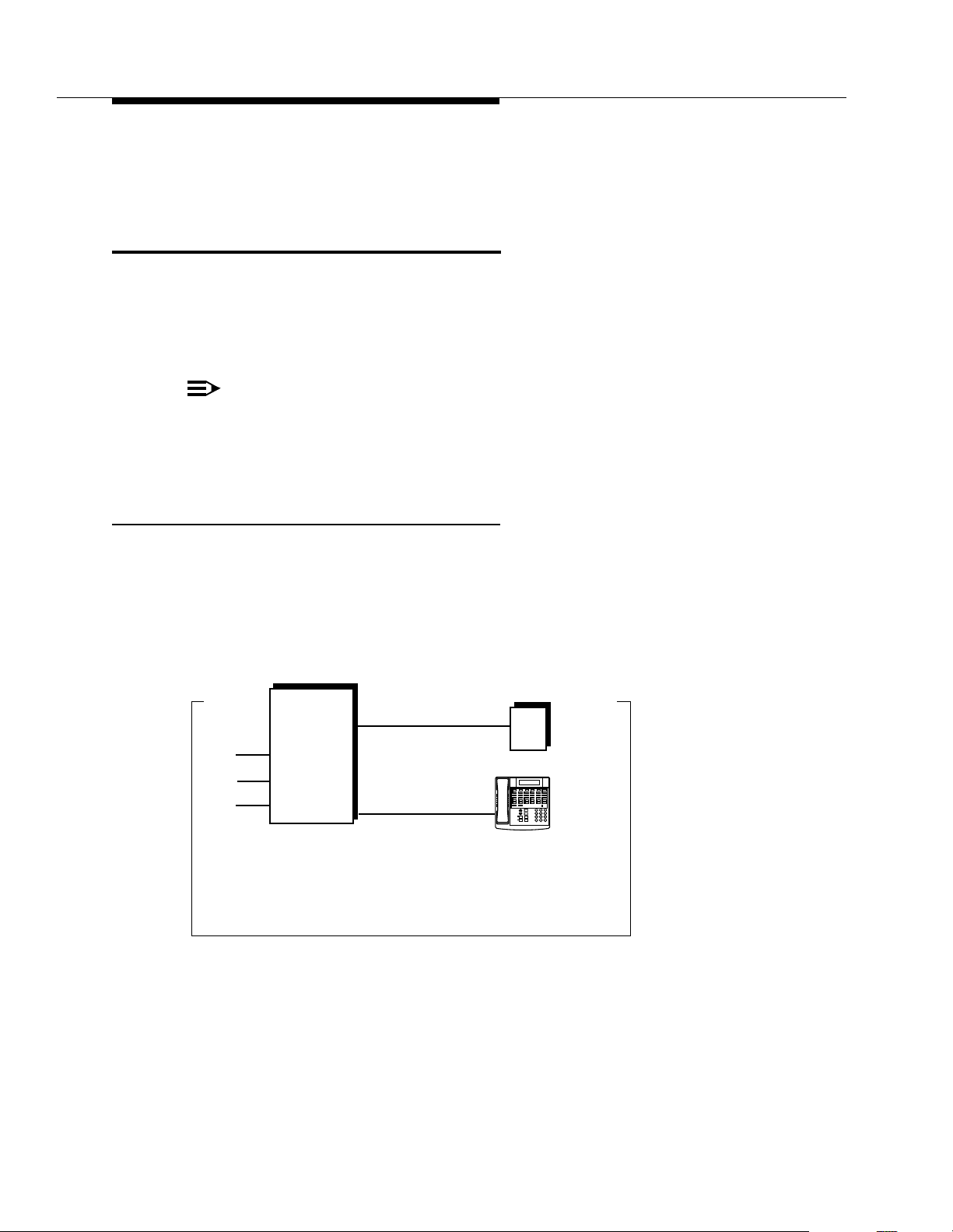
Using Auxiliary Equipment
If you intercept a call from the answering machine, you will hear a click to
notify you that the answering machine has turned off.
Auto Attendant
An auto attendant answers calls and directs them to a specified extension, Calling
Group, or Hunt Group (based on the digits a caller dials after listening to a list of
choices in a recorded greeting). For example, the auto attendant could answer
calls and tell callers to press 1 for Sales, 2 for Parts, 3 for Service, and so on. An
auto attendant can be set up for immediate call handling or delayed call handling.
NOTE:
With the exception of headphones, auxiliary equipment works only on Tip
Ring ports (the bottom two ports of the PARTNER Endeavor 362 processor
or 362EC expansion module). Because headphones do not require a ring,
they can be plugged into any port.
Backup for Receptionist
A common use of an auto attendant is as a backup for the receptionist. If the
receptionist cannot pick up a call within a specified number of rings, the auto
attendant handles it. This prevents calls from going unanswered. Figure 4-4
shows how the auto attendant would be connected to your system.
Auto
Attendant
Lines
CONTROL
Ext. X
UNIT
Message
Ext.
Intercom
Intercom
ABC2DEF
Feature
+
31
–
JKL5MNO
GHI
Conf
6
4
TUV8WXYZ
PQRS
Mic
Transfr
9
7
HFAI
Hold
Spkr
#
0
Ext. 10
*
Receptionist’s Desk
Figure 4-4. Backup for Receptionist
4-8
Page 84
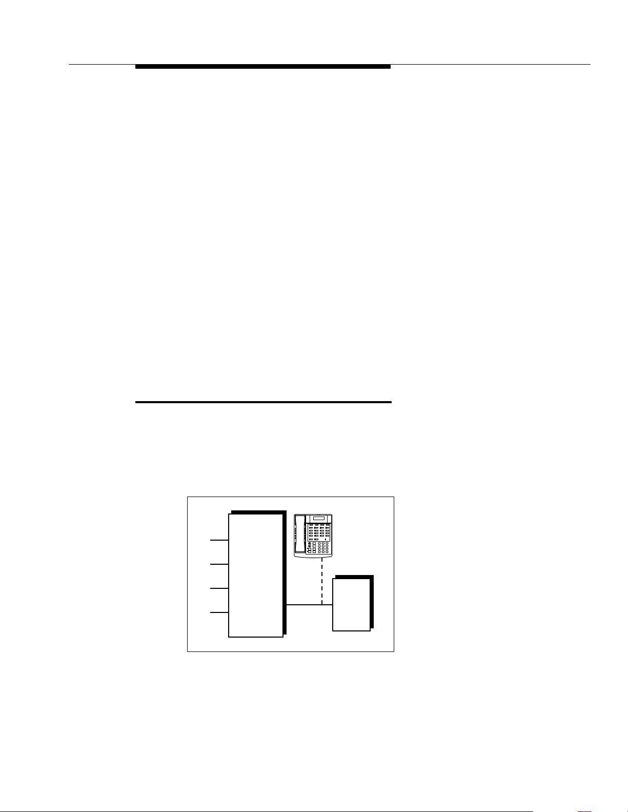
Credit Card Scanners
To Use:
Follow the instructions packaged with the auto attendant. Make sure that the unit
is in backup call-answering mode.
When callers call the main number for your company, the receptionist normally
picks up the call. If the receptionist is busy, the auto attendant answers and plays
a recorded message, such as: “Please hold for the receptionist or dial an
extension number now.”
To Program:
1. Use Line Assignment (#301) to assign all the lines to extension X that you
want the auto attendant to cover.
2. Set Line Ringing for all lines assigned to extension X to Delayed Ring.
3. Make sure extension X is not assigned as a Call Waiting (#316) extension.
4. Use AA Extensions (#607) to identify extension X as the auto attendant.
5. Set Transfer Return Extension (#306) for extension X to extension 10.
6. Set the auto attendant to pick up within a specific number of rings, so if the
receptionist does not pick up a call, the auto attendant will.
Credit Card Scanners
Many retail businesses and restaurants use credit card scanners to get instant
approval of credit card purchases. The system allows your credit card scanners to
share the lines in your system (as shown in Figure 4-5). You can install the credit
card scanner on an extension by itself, or combine it with a system phone or a
standard phone on the same extension (see “Combination Extensions” in the
PARTNER Endeavor Communications System Installation
Lines
CONTROL
UNIT
Figure 4-5. Credit Card Scanner
Ext
X
Ext.
Intercom
Intercom
Feature
+
–
GHI
Conf
4
PQRS
Mic
Transfr
7
HFAI
Hold
Spkr
*
Telephone
(optional)
Message
ABC2DEF
31
JKL5MNO
6
TUV8WXYZ
9
#
0
Credit
Card
Scanner
guide).
4-9
Page 85

Using Auxiliary Equipment
NOTE:
Credit card scanners only work on Tip Ring ports, which are the bottom two
ports of the PARTNER Endeavor 362 processor module or 362EC
expansion module.
Using Credit Card Scanners
When you make a call on the credit card scanner, an outside line is automatically
selected. If you combine the credit card scanner with a system phone or standard
phone, you cannot use the phone while the credit card scanner is operating. You
can use only one of the devices at a time.
Programming Credit Card Scanners
1. If extension X is a key extension, use Line Assignment (#301) to assign
the lines you want the scanner to use to extension X.
If extension X is a pooled extension, use Pool Extension Assignment
(#314) to assign the pools you want the scanner to use to extension X. Also
use Line Assignment (#301) to assign any individual lines you want the
scanner to use to extension X.
2. Set Automatic Line Selection for extension X to select the pools and
outside lines that the scanner is to use.
3. Set Automatic Extension Privacy (#304) for extension X to Assigned.
4. Make sure extension X is not assigned as a Call Waiting (#316) extension.
5. If the scanner has an auto answer feature, turn it off.
6. For multiple scanners, repeat Steps 1–5 for each extension.
Fax Machines
This section suggests several ways you can set up fax machines to work with your
system. It includes instructions for programming and using a Fax Management
button on a system phone (in order to monitor the status of a fax machine and
transfer calls to it with a single touch), and for transferring calls to the fax machine
extension.
NOTE:
Fax machines only work on Tip Ring ports, which are the bottom two ports
of the PARTNER Endeavor 362 processor module or 362EC expansion
module.
4-10
Page 86

Fax Machines
Using the Fax Management Feature
On any system phone, you can program a button with lights to serve as a Fax
Management button. The lights next to this button tell you when the fax machine is
in use, available, or not answering (for example, when it is out of paper). You can
also use the button to transfer calls from your extension to the fax machine with a
single touch.
Programming for Fax Management
To program a Fax Management button, first assign the fax machine extension
using Fax Machine Extensions (#601). (See Chapter 5 for details.) Then
program the fax machine extension number on an Auto Dial button. For more
information, see ‘‘Auto Dialing’’ on page 5-13.
Using the Fax Management Button
The lights next to the Fax Management button show what is happening at the fax
machine.
Table 4-1. Fax Management Button Light Patterns
Light Pattern... Indicates...
Red broken flutter Fax trouble. The fax machine is not answering. If
broken flutter occurs because the fax machine is out
of paper, refill the paper. The light clears the next
time the machine transmits or receives a call. If the
machine takes longer than four rings to answer, the
light shows fax trouble; when the machine does
answer, the light changes to fax busy (red steady).
Red steady Fax busy. The fax machine is busy transmitting or
receiving a call.
Green flutter Fax transfer return. A call you transferred to the fax
machine was not answered and is returning to you.
4-11
Page 87

Using Auxiliary Equipment
Transferring a Call to th e Fax Machine
There are two situations in which you would want to transfer a call to your fax
machine:
■ You answer an outside call and hear a fax machine signaling. (A fax signal
is a single beep sequence—
should transfer the call immediately to the fax machine extension.
■ You are on a call with a person who wants to send you a fax using the fax
machine that is connected to his or her phone. You can receive the fax by
transferring the call to your fax extension. T ell the other party to wait until he
or she hears the fax signal before pressing the Start button on the sending
fax machine.
In addition, if you have a PARTNER MAIL system and a fax call comes in on a line
covered by the PARTNER MAIL system, its Automated Attendant Service can be
programmed to automatically transfer the call to a fax extension or (if you have
multiple fax machines) to the extension Hunt Group for the fax machines.
There are four ways to transfer the call to the fax extension:
beep.... beep.... beep
). If you hear this, you
■ If you have a Fax Management button, simply press the button. When the
fax machine answers, hang up.
■ If you do not have a Fax Management button, press & plus the fax
machine’s extension number. When the fax machine answers, hang up.
■ On a standard phone, rapidly press and release the switchhook to place
the call on hold, then dial the fax extension number and hang up.
■ If you have multiple fax machines in an extension Hunt Group, press
&, then i 7 7 plus the fax extension Hunt Group number.
When a fax machine answers, hang up.
Setting Up Fax Machines
There are many ways to set up fax machines. The following configurations are
basic and easy to use:
■
Single fax machine.
setup uses a published fax number.
■
Fax machine line saver .
published fax number.
■
Send and receive fax machines.
machine sends, the other receives.
Good for light or moderate fax traffic. This basic
Good for light fax traffic, with no need for a
Good for high-volume fax traffic. One
4-12
You can install both a telephone and a fax machine on the same extension—see
“Combination Extensions” in the
Installation
guide. This lets you receive both voice and fax calls on the same line
PAR TNER Endeavor Communications System
(but not at the same time). If you pick up the phone and hear a fax signal, push the
Start button on your fax machine and then hang up.
Page 88

Fax Machines
If you are using the PARTNER MAIL system’s Automated Attendant Service, you
can program PARTNER MAIL to transfer fax calls to the fax extension or a group
of fax extensions automatically. Use Fax Machine Extensions (#601) to identify
fax extensions. If you have multiple fax machines, put all of the fax extensions into
a single Hunt Group (any group 1–6) using Hunt Group Extensions (#505).
Restricting Dialing from a Fax Machine
You can use dialing restrictions to restrict calling activity on a fax machine. For
example, you can use Outgoing Call Restriction (#401) to restrict the fax
machine to local calls only. For a more detailed discussion of dialing restrictions,
see Chapter 2.
Single Fax Machine
The single fax machine setup (shown in Figure 4-6) is good for moderate traffic.
The fax machine has its own line (line A), the number of which is published as the
fax number. (The fax line can be used by other phones when all other lines are
busy.) The fax machine is connected to its own extension (extension X).
Fax
Line A
Figure 4-6. Single Fax Machine
CONTROL
UNIT
Ext
X
FAX
To Use:
The fax machine automatically answers all calls that come in on the fax line. If a
call comes in on another line, you can transfer the call to the fax extension (see
‘‘Transferring a Call to the Fax Machine’’ on page 4-12). If you have
programmed a Fax Management button, you can transfer a call to the fax
machine with a single touch, as well as monitor the status of the fax machine (see
‘‘Using the Fax Management Feature’’ on page 4-11).
When you send a fax, the system automatically selects the fax line.
4-13
Page 89

Using Auxiliary Equipment
To Program:
1. If extension X is a key extension, use Line Assignment (#301) to assign
only
line A to extension X.
If extension X is a pooled extension, use Pool Line Assignment (#207) to
remove line A from all pools and then use Line Assignment (#301) to
assign only line A to extension X.
2. Set Automatic Line Selection for extension X to select line A only. Set
Automatic Line Selection to select line A last on all other extensions or
remove line A from all other extensions if they should not use it to make
outgoing calls.
3. Set Line Ringing for line A on extension X to Immediate Ring. On all other
extensions, set line A to Delayed Ring or No Ring.
4. Set Automatic Extension Privacy (#304) for extension X to Assigned.
5. Make sure extension X is not assigned as a Call Waiting (#316) extension,
Pickup Group Extension (#501), Calling Group Extension (#502), Night
Service Group Extension (#504), or Hun t Grou p Exte nsio n (#505 ).
6. To monitor the fax machine, use Fax Machine Extensions (#601) to
identify extension X as a fax extension and program a Fax Management
button by programming the fax machine extension number on an Auto Dial
button.
Fax Line Saver
If you do not use your fax machine enough to justify paying for its own outside line,
you can put the machine on its own extension. With this setup, you must transfer
calls to it manually . If you have programmed a Fax Management button, you can
transfer a call to the fax machine with a single touch, as well as monitor the status
of the fax machine (see ‘‘Using the Fax Management Feature’’ on page 4-11).
Figure 4-7 shows the setup.
Lines
A
B
C
Figure 4-7. Fax Line Saver Setup
CONTROL
UNIT
Ext X
FAX
4-14
Page 90

Fax Machines
To Use:
When a person answers a call and hears a fax machine signaling on the other
end, the person can transfer the call to extension X—the fax machine extension.
To send a fax transmission, simply lift the handset on the fax machine—an outside
line will be automatically selected.
To Program:
1. If extension X is the key extension, use Line Assignment (#301) to assign
all lines to extension X.
If extension X is a pooled extension, use Pool Extension Assignment
(#314) to assign the pools you want the fax machine to use to extension X.
Also use Line Assignment (#301) to assign any individual lines you want
the fax machine to use to extension X.
2. If extension X is a key extension, set Automatic Line Selection for
extension X to line A, B, C,....
If extension X is a pooled extension, set Automatic Line Selection for
extension X to Pool D, line A, B, C,....
3. Set Line Ringing for all lines and pools on extension X to No Ring.
4. Set Automatic Extension Privacy (#304) for extension X to Assigned.
5. Make sure extension X is not assigned as a Call Waiting (#316) extension,
Pickup Group Extension (#501), Calling Group Extension (#5 02), Night
Service Group Extensio n (#504 ), or Hunt Group Extension (#505).
6. To monitor the fax machine, use Fax Machine Extensions (#601) to
identify extension X as a fax extension and program a Fax Management
button by programming the fax machine extension number on an Auto Dial
button.
4-15
Page 91

Using Auxiliary Equipment
Send and Receive Fax Machines
If your business has high-volume fax traffic, you can set up two fax machines, one
that only sends and the other that only receives. For example, in Figure 4-8, fax 1
send
is the
number of which is published as the fax number. If fax 2 doesn’t answer line A, fax
1 will. The receive fax must be on one of the bottom two ports of the processor or
362EC expansion module.
Fax
Line A
Lines
machine, fax 2 is the
CONTROL
UNIT
Ext X
Ext Y
receive
FAX 1
Send
FAX 2
Receive
machine. Line A is the fax line, the
Figure 4-8. Send and Receive Fax Machines
NOTE:
To receive a fax, fax machines rely on an incoming signal to ring. Fax
machines only work on Tip Ring ports, which are the bottom two ports of the
PARTNER Endeavor 362 processor or 362EC expansion module. Fax
machines that are used for sending only may be used at any port.
To Use:
When you send a fax, an outside line will be automatically selected. Incoming fax
calls on the fax line are answered automatically by fax 2. If a fax comes in on a line
other than line A, you can transfer the call to fax 2 (see ‘‘Transferring a Call to
the Fax Machine’’ on page 4-12). If you have programmed a Fax Management
button, you can transfer a call to the fax machine with a single touch, as well as
monitor the status of the fax machine (see ‘‘Using the Fax Management
Feature’’ on page 4-11). If fax 1 is set for Delayed Ring on line A, fax 1 can pick
up fax transmissions when fax 2 does not answer.
To Program Fax 1 (Send—Ext. X)
1. If extension X is a key extension, use Line Assignment (#301) to assign
one or more lines to extension X (including line A).
If extension X is a pooled extension, use Pool Line Assignment (#207) to
remove line A from all pools. Then use Pool Extension Assignment
(#314) to assign pools to extension X. Also use Line Assignment (#301)
to assign line A and any other individual lines to extension X.
4-16
Page 92

Fax Machines
To Program Fax 2 (Receive—Ext. Y)
2. Set Automatic Line Selection for extension X to select outside lines first
(line A selected last).
For pooled extensions, set Automatic Line Selection for extension X to
select pools and outside lines first (line A selected last).
3. Set Line Ringing for line A at extension X to Delayed Ring; set all other
lines and pools to No Ring.
4. Set Automatic Extension Privacy (#304) for extension X to Assigned.
5. Make sure extension X is not assigned as a Call Waiting (#316) extension,
Pickup Group Extension (#501), Calling Group Extension (#5 02), Night
Service Group Extensio n (#504 ), or Hunt Group Extension (#505 ).
6. To monitor the fax machine at extension X, use Fax Machine Extensions
(#601) to identify extension X as a fax extension and program a Fax
Management button by programming the fax machine extension number on
an Auto Dial button.
1. If extension Y is the key extension, use Line Assignment (#301) to assign
only
line A to extension Y.
If extension Y is a pooled extension, use Pool Line Assignment (#207) to
remove line A from all pools and then use Line Assignment (#301) to
assign line A and any other individual lines to extension Y.
2. If you want it to be able to dial out when fax 1 is unavailable, set Automatic
Line Selection for extension Y to select outside lines first (line A selected
last).
3. Set Line Ringing for line A at extension Y to Immediate Ring; set all other
lines and pools at extension Y to No Ring. (For all other extensions, set line
A to No Ring or Delayed Ring.)
4. Set Automatic Extension Privacy (#304) for extension Y to Assigned.
5. Make sure extension Y is not assigned as a Call Waiting (#316) extension,
Pickup Group Extension (#501), Calling Group Extension (#5 02), Night
Service Group Extensio n (#504 ), or Hunt Group Extens ion (#505) .
6. To monitor the fax machine at extension Y, use Fax Machine Extensions
(#601) to identify extension Y as a fax extension and program a Fax
Management button by programming the fax machine extension number on
an Auto Dial button.
4-17
Page 93

Using Auxiliary Equipment
Modems
There are several ways to use modems with your system, as described below.
NOTE:
Modems can connect directly to an extension jack without an adapter.
However, if you connect a high-speed modem through the control unit, you
may experience some degradation of efficiency and throughput, depending
on the quality of the central office lines connected to the system. To solve
the problem, either connect modems directly to the network interface jacks,
or contact your local telephone company for information about upgrading
line quality.
Stand-Alone Modem for Placing Calls Only
A modem and a terminal allow you to dial out and connect to computer bulletin
boards and other data services. This setup, which lets you dial out but not receive
calls, is shown in Figure 4-9. Note that the telephone is optional and can be used
if you want the terminal to share an extension with a phone on any port.
Lines
CONTROL
UNIT
Ext
X
Telephone
(optional)
Intercom
Intercom
Feature
+
–
Conf
Mic
Transfr
HFAI
Hold
Spkr
Modem
Message
Ext.
ABC2DEF
31
JKL5MNO
GHI
6
4
TUV8WXYZ
PQRS
9
7
#
0
*
PC or
Terminal
Figure 4-9. Stand-Alone Modem for Placing Calls Only
To Use:
Follow the modem manufacturer’s instructions.
To Program:
1. If extension X is a key extension, use Line Assignment (#301) to assign
one or more lines to extension X.
If extension Y is a pooled extension, use Pool Extension Assignment
(#314) to assign the pools you want the modem to use to extension X. Also
use Line Assignment (#301) to assign any individual lines you want the
modem to use to extens ion X.
4-18
Page 94

Modems
2. If the modem will only dial outside the system, set Automatic Line
Selection for extension X to select outside lines first. If you also use the
modem for calls within the system, set Automatic Line Selection to select
intercom first, and include a 9 or a pool access code and a couple of
pauses in the modem’s dialing sequence for outside calls.
3. Set Line Ringing for all lines and pools assigned to extension X to No
Ring.
4. Set Automatic Extension Privacy (#304) for extension X to Assigned.
5. Make sure extension Y is not assigned as a Call Waiting (#316) extension,
Pickup Group Extension (#501), Calling Group Extension (#5 02), Night
Service Group Extensio n (#504 ), or Hunt Group Extension (#505 ).
6. Set the auto answer feature of the modem to Off.
Send and Receive Modem
If you need to place and receive calls with the modem, use the setup shown in
Figure 4-10. This setup makes line A the primary modem line, but keeps the line
available for users at other extensions when all other lines are busy.
NOTE:
To receive information, modems rely on an incoming signal to ring. Modems
only work on Tip Ring ports, which are the bottom two ports of the
PARTNER Endeavor 362 processor or 362EC expansion module. Modems
that are used for sending only may be used at any port.
Modem
Line A
Lines
Figure 4-10. Send and Receive Modem
CONTROL
UNIT
Ext
X
MODEM
To Use:
Calls on the modem line (line A) ring only at extension X. Also, line A is the
line selected by other extensions, so the modem line is unavailable for the modem
only when all other lines in the system are being used
.
last
4-19
Page 95

Using Auxiliary Equipment
To Program:
1. If extension X is a key extension, use Line Assignment (#301) to assign
one or more lines to extension X (including line A).
If extension X is a pooled extension, use Pool Line Assignment (#207) to
remove line A from all pools. Then use Pool Extension Assignment
(#314) to assign pools to extension X. Also use Line Assignment (#301)
to assign line A and any other individual lines to extension X.
2. For extension X, set Automatic Line Selection to select pools and outside
lines first (line A selected first).
For all other extensions, set Automatic Line Selection so that line A is the
last line in the select sequence. That way, the modem line is used for
outgoing voice calls only when all other lines are busy.
3. Set Line Ringing for line A at extension X to Immediate Ring. Set all other
lines or pools assigned to extension X to No Ring. (For all other extensions,
set line A to No Ring.)
4. Set Automatic Extension Privacy (#304) for extension X to Assigned.
5. Make sure extension X is not assigned as a Call Waiting (#316) extension,
Pickup Group Extension (#501), Calling Group Extension (#502), Night
Service Group Extension (#504), or Hun t Grou p Exte nsio n (#505 ).
Night Service with Auxiliary Equipment
You can set up modems, fax machines, and answering machines to receive calls
automatically after hours. When Night Service is on, calls ring immediately at the
appropriate extensions, so that no human intervention is required to transfer calls
to the fax, modem, or answering machine. When Night Service is off, you can use
the auxiliary equipment lines for normal business purposes, so that lines are
only
dedicated to auxiliary equipment
NOTE:
With the exception of headphones, auxiliary equipment works only on Tip
Ring ports (the bottom two ports of the PARTNER Endeavor 362 processor
or 362EC expansion module). Because headphones do not require a ring,
they can be plugged into any port.
By putting auxiliary equipment in the Night Service Group as described in this
section, auxiliary equipment can start ringing and answering calls whenever you
turn Night Service on. In other words, the Night Service button at extension 10
acts like a switch, turning auxiliary equipment on and off, as well as putting the
system into Night Service.
NOTE:
If you have a voice messaging system, turning Night Service on
activates Night Service operation of the voice messaging system.
after hours.
also
4-20
Page 96

Night Service with Auxiliary Equipment
Figure 4-11 shows a system with a fax machine and a modem connected to
separate extensions. Line A is published as the fax line, and line B is published as
the modem line.
Lines
A
CONTROL
B
C
Figure 4-11. Night Service with Fax Machine and Modem
UNIT
Ext
X
Ext
Y
FAX
MODEM
Using Night Service with Auxiliary Equipment
During the day, lines A and B do not ring at extensions X and Y. When you turn
Night Service on, calls on line A ring immediately at the fax (extension X). Since
that line is not assigned to any other extension in the Night Service Group, only
extension X receives fax transmissions. Likewise, with Night Service on, calls on
line B ring immediately at the modem (extension Y).
NOTE:
If answering machines are connected to Night Service extensions, you can
join a call that was already answered by an answering machine from any
system phone. If you have a Lucent Technologies answering machine with
the Call Intercept feature, the answering machine drops off the call when
you join it.
Programming Night Servic e with Auxiliary
Equipment
Use the following procedure to program Night Service with auxiliary equipment.
1. If extension X and Y are key extensions, use Line Assignment (#301) to
assign only line A to extension X (for the fax machine to cover) and only line
B to extension Y (for the modem to cover).
If extensions X and Y are pooled extensions, use Pool Line Assignment
(#207) to remove lines A and B from all pools and Pool Extension
Assignment (#314) to remove all pools from extensions X and Y. Also use
Line Assignment (#301) to assign only line A to extension X (for the fax
machine to cover) and only line B to extension Y (for the modem to cover).
4-21
Page 97

Using Auxiliary Equipment
2. Set Line Ringing for line A at extension X and for line B at extension Y to
No Ring.
3. Make sure extensions X and Y are not assigned as Call Waiting (#316)
extensions, Pickup Group Extensions (#501), Calling Group
Extensions (#502), or Hunt Group Extensions (#505).
4. Assign a Night Service Button (#503) at extension 10.
5. Assign extensions X and Y to the Night Service Group (#504).
Voice Messaging Systems
Three Lucent Technologies voice messaging systems are compatible with your
system. You can install one of the three depending on your business needs:
■ The PARTNER MAIL VS Voice Messaging System resides in the control
unit. It is recommended that this system be installed in the last slot.
■ The PARTNER MAIL V oice Messaging System is an auxiliary device that
connects to the system through extension jacks.
NOTE:
With the exception of headphones, auxiliary equipment works only on Tip
Ring ports (the bottom two ports of the PARTNER Endeavor 362 processor
module or 362EC expansion module). Because headphones do not require
a ring, they can be plugged into any port.
■ The PARTNER Voice Messaging PC Card is a PC card voice messaging
system.
All three Voice Messaging Systems offer your business
complete
call processing
features. Specifically, they can:
■ Insure that incoming calls are answered and directed to destination
extensions correctly and efficiently, using immediate or delayed call
handling. (Immediate call handling sends calls directly to the voice
messaging system, while delayed call handling allows the receptionist to
answer calls first.)
■ Answer and route calls during the day and after normal business hours.
■ Alleviate the problem of inaccurate or incomplete messages by allowing
callers to leave detailed, confidential messages for subscribers.
■ Allows subscribers to assign a password to their mailbox, change their
personal greeting, and retrieve messages. Voice mail passwords should be
changed periodically to help ensure privacy and to help prevent
unauthorized use and toll fraud.
4-22
The PARTNER MAIL system also offers advanced voice mail features, such as
outcalling, group lists, broadcast messages, and fax management. For complete
details, contact your Lucent Technologies Representative or local Authorized
Dealer, or refer to the documentation provided with the voice messaging system.
Page 98
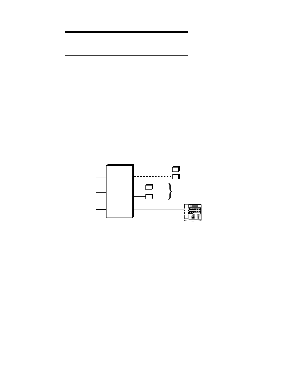
Voice Messaging Systems
Delayed Call Handling
Figure 4-12 shows a PARTNER MAIL VS system that provides delayed call
handling. This setup allows the receptionist at extension 10 to provide
personalized service by answering calls during normal business hours. The
PARTNER MAIL VS system (connected to extensions Z1 and Z2) handles calls
when the receptionist is busy or not available, so calls do not go unanswered. The
P ARTNER MAIL VS system also answers calls received outside of business hours
and prompts callers to leave a message in the receptionist’s mailbox.
This example also includes two user extensions (X and Y), which are not
automatically covered by the PARTNER MAIL VS system. This allows the
receptionist to give the caller more personalized service; if the receptionist
transfers a call to extension X or Y and that extension does not answer, the call
returns to the receptionist. The receptionist can then take a message or send the
call to the extension’s mailbox if the caller prefers.
Lines
PARTNER MAIL VS
System
Ext. Z1
Ext. Z2
CONTROL
UNIT
Receptionist’s Desk
Ext. X
Ext. Y
Ext. 10
(not automatically covered by
the PARTNER MAIL VS System)
Message
Ext.
Intercom
Intercom
ABC DEF
Feature
+
2 31
–
JKL MNO
GHI
Conf
5 6
4
TUV WXYZ
PQRS
Mic
Transfr
8 9
7
HFAI
Hold
Spkr
#
0
*
Figure 4-12. Delayed Call Handling
To Use:
Follow the instructions packaged with the PARTNER MAIL VS system to install.
During normal business hours, the PARTNER MAIL VS system uses delayed call
handling; the receptionist picks up all calls at extension 10. If the receptionist
cannot answer within four rings, the system routes the call to the PARTNER MAIL
VS system where the day menu plays to the caller. Outside of business hours
(when Night Service is activated at extension 10), outside calls are answered
directly by the PARTNER MAIL VS system. Any user who is in the office can pick
up calls before the PARTNER MAIL VS system answers.
4-23
Page 99

Using Auxiliary Equipment
To Program:
The following list summarizes the PARTNER Endeavor Communications System
programming procedures you use to implement the previous example:
1. Use Group Call Distribution (#206) to assign all outside lines to Hunt
Group 7 (the VMS hunt group) to provide Automated Attendant Service on
these lines.
2. Use Transfer Return Extension (#306) for extensions Z1 and Z2 to
ensure that calls transferred by the PARTNER MAIL VS system return to
extension 10 if they are not answered.
3. Use Hunt Group Extensions (#505) to assign extensions Z1 and Z2 to
Hunt Group 7 (the VMS hunt group).
4. Set the VMS Hunt Delay (#506) to Delayed.
5. Set the VMS Hunt Schedule (#507) to Always.
6. Make sure that a Night Service Button (#503) is assigned at extension
10—the receptionist’s extension. When Night Service is on, callers hear the
night menu when no one is available to answer their calls.
7. Program a Voice Mailbox Transfer button at extension 10 to enable the
receptionist to transfer calls directly to extension X’s and Y’s mailboxes
without first ringing their phones. (This is useful when the receptionist
knows that the users at extensions X and Y are away from their desks.)
8. Program an Auto Dial button for the VMS hunt group (
extensions X and Y to allow the subscribers to call in for their messages
with one touch.
i 7 7 7) at
4-24
Page 100

Feature Refer ence
Overview
This chapter provides reference information for programming and using system
features.
procedures include the procedure code (# and three-digit number) in the heading;
dial-code features include the feature code (F for
two- or three-digit code). Headings without codes are general call-handling topics
or Telephone Programming procedures.
Each feature includes the following information, if applicable:
Features are listed in alphabetical order.
System Programming
f or I for i, plus a
■ Description ■ Examples
■ Related Features ■ Programming
■ Considerations ■ Using
■ Valid Entries (✔ = factory setting)
This chapter gives step-by-step instructions, using the following conventions:
■ All of the instructions in this chapter assume that system phones select
outside lines or pools first and standard phones select intercomStandard
phones; Automatic Line Selection for first (as determined by each
extension’s setting for Automatic Line Selection).
See Chapter 2 for a review of the methods and buttons you can use while
in programming mode.
■ Programming instructions tell you to use the D button to change
values for specific settings. You can, however, enter a value using the
dialpad if you prefer. Similarly, there are different ways to exit programming
mode as described in Chapter 2—use the method with which you are most
comfortable.
■ For Telephone Programming, this chapter provides only the instructions for
Centralized Telephone Programming.
■ Display prompts in the chapter are shown as they appear on PARTNER
Endeavor-model phones.
5-1
 Loading...