

Page 1

Manual
August 2000
Venus
®
AT Command Re ference Manual
C
o
n
t
e
n
t
s
In
tr
o
d
u
c
tio
n
...
....
..
.......
......
.......
......
...
....
......
.....
..
......
..
1
A
T
C
o
m
m
a
n
d
S
e
t
.
.......
....
..
.......
......
.
.....
.......
...
...
.......
2
T
e
s
t
a
n
d
D
e
b
u
g
A
T
C
o
m
m
a
n
d
s
......
.
......
.......
.
.....
...
2
4
R
e
s
u
lt
C
o
d
e
s
....
.
.......
......
.
......
......
....
...
......
......
.
......
.
3
4
S
-
R
e
g
is
te
r
s
....
...
...
.......
.....
.
.......
......
..
....
.......
....
..
......
3
6
F
A
X
C
o
m
m
a
n
d
s
....
......
....
...
......
.......
......
.......
..
....
....
4
8
V
.2
5
te
r
C
o
m
m
a
n
d
s
.
......
..
.....
......
.....
..
......
.......
......
..
5
4
V
.8
0
A
T
C
o
m
m
a
n
d
s
..
......
.......
......
...
...
.......
.....
.
.......
6
5
A
T
V
o
ic
e
C
o
m
m
a
n
d
s
.
.....
..
......
.......
.
.....
.......
...
...
.....
6
7
In
t
r
o
d
u
c
t
io
n
T
h
is
d
o
c
u
m
e
n
t s
p
e
c
ifie
s
th
e
A
T
c
o
m
m
a
n
d
s
e
t f
o
r
th
e
L
u
c
e
n
t
T
e
c
h
n
o
lo
g
ie
s
V
e
n
u
s
c
h
ip
s
e
t.
N
o
te
th
a
t
if
a
p
a
r
tic
u
l
a
r
m
o
d
e
m
b
o
a
r
d
d
o
e
s
n
o
t s
u
p
p
o
r
t a
fe
a
tu
r
e
,
s
u
c
h
a
s
v
o
ic
e
, th
e
n
th
e
c
o
r
r
e
s
p
o
n
d
in
g
c
o
m
m
a
n
d
s
a
r
e
d
is
a
b
le
d
fo
r
th
a
t m
o
d
e
.
Page 2

2 Lucent Technologies Inc.
Manual
August 2000
Venus
AT Command Reference Manual
AT Command Set
AT commands are issued to the modem to control the modem’s operation and software configuration. AT commands can only be entered while the modem is in command mode. The format for entering commands is ATXn
where X is the AT command and n is the specific value for that command.
Any command issued is acknowledged with a response in either text or numeric values. These responses are
known as result codes. The result codes are listed in Table 59.
Commands may be executed while in COMMAND mode, which is entered under one of the following conditions:
■ After powerup, at the termination of a connection, or after the execution of a command other than dial or answer.
■ Upon the receipt of the escape sequence (three consecutive characters matching the contents of register S2)
while in on-line mode.
■ Upon the on-to-off transition of DTR if &D1, &D2, or &D3 has been set.
Table 1. AT Command Set Summary
*
MNP
is a trademark of Microcom, Inc.
Command Description Command Description
A/ Repeat last command. &Qn Asynchronous communications mode.
A Answer. &Sn Data set ready (DSR) option.
Bn Communication standard setting. &Tn Self-test commands.
Cn Carrier control. &Vn View active configuration.
Dn Dial. &Wn Store current configuration.
En Echo command. &Yn Select stored profile for hard reset.
Fn On-line data character echo command. &Zn Store telephone number.
Hn Hook control. \An Select
MNP
* bloc k size.
In Request ID information. \Bn Send break.
Ln Speaker volume. \Gn Modem port flow control.
Mn Speaker control. \Jn Adjust bits/s rate control.
Nn Modulation handshake. \Kn Set break control.
On Return to on-line data mode. \Nn Select error control mode.
P Select pulse dialing. \Qn Local flow control selection.
Qn Result code control. \Rn Ring indicator off after answer.
T Select tone dialing. \Tn Inactivity timer.
Vn DCE response format. \Vn Protocol result code.
Wn Result code option. \Xn XON/XOFF pass through.
Xn Select result code and monitor call progress. %Bn View numbers in blacklist.
Yn Long-space disconnect. %Cn Data compression control.
Zn Reset and recall stored profile. %En Auto fallback/fallforward control.
&Bn V.32 auto retrain. )C Enable Direct Connect.
&Cn Data carrier detect (DCD) control. &&C Write to/read from DSP register.
&Dn Data terminal ready (DTR) control. &&L Line-to-line loopback.
&Fn Restore factory default configuration. &&R Write to/read from DSP RAM location.
&Gn V.22bis guard tone control. &&S Speaker codec loopback.
&Jn Auxiliary relay options. %T94 Test ex ternal RAM.
&Kn Local flow control selection. %T124 Test DSP 56K version in external RAM.
&Mn Asynchronous communications mode. %T125 Test DSP 56K version in external RAM.
&Pn Pulse dial make-to-break ratio selection. #UD Unimodem diagnostics.
Page 3

Lucent Technologies Inc. 3
Manual
August 2000
Venus
AT Command Reference Manual
AT Command Set (continued)
Escape Sequence
The escape sequence allows the modem to exit data mode and enter on-line command mode. While in on-line
command mode, you may communicate directly to the modem using AT commands. Use the On command to
return to data mode.
A pause, the length of which is set by the escape guard time (register S12), must be used before and after an
escape sequence is issued. This pause prevents the modem from interpreting the escape sequence as data. The
value of the escape sequence character may be changed using register S2.
A/—Repeat Last Command
The A/ command instructs the modem to repeat the last AT command. It will repeat the command already in the
command buffer. This command does not require the AT prefix and does not have to be followed by the terminator
character. It is primarily used to redial the last number in the case of a busy signal.
A—Answer
This command instructs the modem to go off-hook and answer an incoming call.
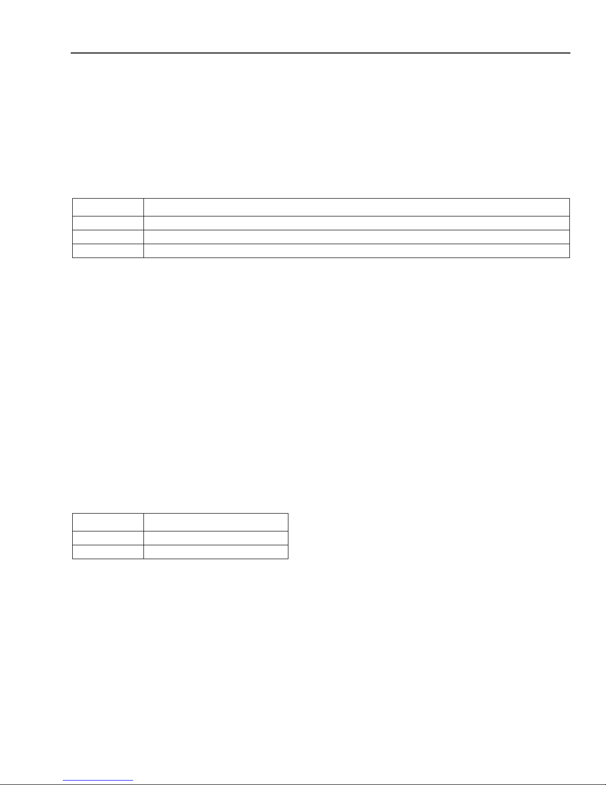
Bn—Communication Stand ard Setting
This command determines the communication standard used by the modem.
Result codes:
■ OK if n = 0—3, 15, 16.
■ ERROR if n
≠
0—3, 15, 16.
Table 2. Bn Commands
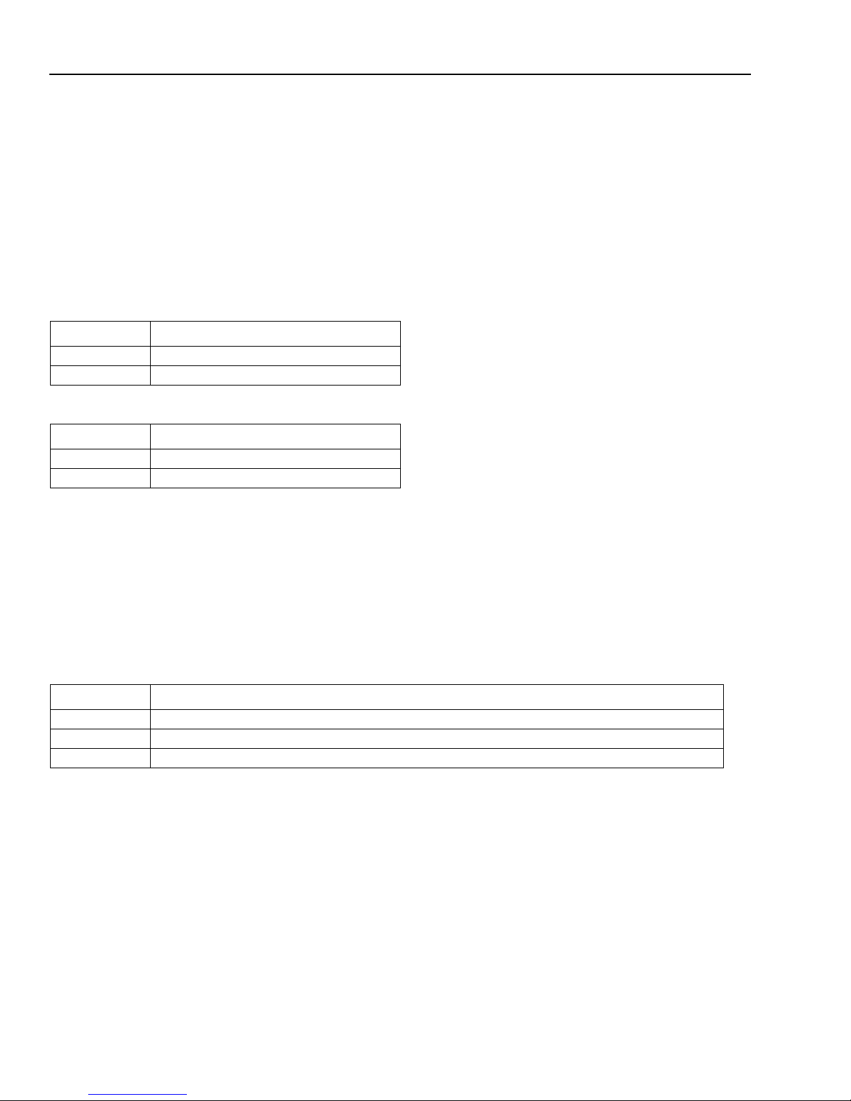
Cn—Carrier Control
The modem will accept the C1 command without error in order to ensure backward compatibility with communications software that issues the C1 command. However, this modem does not support the C0 command. The C0
command may instruct some other modems not to send carrier (i.e., it puts them in receive-only mode).
Result codes:
■ OK if n = 1.
■ ERROR if n ≠ 1.
Command Function
B0 Selects CCITT V.22 mode when the modem is at 1200 bits/s.
B1 Selects Bell 212A when the modem is at 1200 bits/s (default).
B2 Deselects V.23 reverse channel (same as B3).
B3 Deselects V.23 reverse channel (same as B2).
B15 Selects V.21 when the modem is at 300 bits/s.
B16 Selects Bell 103J when the modem is at 300 bits/s (default).
Page 4

4 Lucent Technologies Inc.
Manual
August 2000
Venus
AT Command Reference Manual
AT Command Set (continued)
Table 3. Cn Commands
Dn—Dial
This command instructs the modem to go off-hook and begin the dialing sequence. The dial string (n, including
modifiers and the telephone number) is entered after the ATD command.
A dial string can be up to sixty characters long. Any digit or symbol may be dialed as touchtone digits. Characters
such as spaces, hyphens, and parentheses are ignored by the modem and may be included in the dial string to
enhance readability.
Table 4. Dial Modifiers
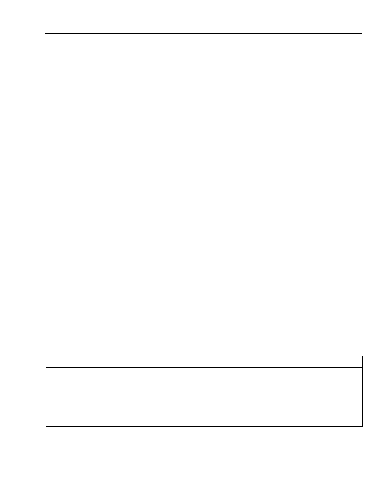
En—Echo Command
This command controls whether or not the characters entered from the computer keyboard are echoed back to the
monitor while in command mode.
Result codes:
■ OK if n = 0—1.
■ ERROR if n ≠ 0—1.
Table 5. En Commands
Command Function
C0 Transmit carrier always off (not supported).
C1 Normal transmit carrier switching (default).
Modifier Function
L Dial the last number. This modifier is valid only if it is the first symbol of the dial string. All con-
secutive characters are discarded.
P Use pulse dialing.
T Use tone dialing (default).
W Wait for dial tone. The modem will wait for a second dial tone before processing the dial string.
V The modem switches to speakerphone mode and dials the number. The Hn command may be
used to disconnect the voice call.
, Dial pause. The modem will wait for the time specified by register S8 before continuing to dial.
! Hook flash. The modem will go on-hook for 0.5 seconds and then return to off-hook.
@ W ait for quiet answ er . The modem will wait for 5 seconds of silence after dialing the number. If
silence is not detected, the modem sends a NO ANSWER result code back to the user.
; Return to command mode. This modifier instructs the modem to return to command mode
after it has finished dialing without disconnecting the call.
^ Disable data calling tone transmission.
$ Bong tone detection.
S=n Dial a telephone number previously stored using the &Zn=x command. The range is 0—2.
Command Function
E0 Disables echo command.
E1 Enables echo command (default).
Page 5

Lucent Technologies Inc. 5
Manual
August 2000
Venus
AT Command Reference Manual
AT Command Set (continued)
Fn—On-Line Data Character Echo Command
This command determines if the modem will echo data from the DTE. The modem does not support the F0 version
of the command. However, to ensure backward compatibility, the modem will accept F1, which may be issued by
older communication software.
Result codes:
■ OK if n = 1.
■ ERROR if n
≠
1.
Table 6. Fn Commands
Hn—Hook Control
This command instructs the modem to go either on-hook to disconnect a call or off-hook to make the telephone line
busy.
Result codes:
■ OK if n = 0—1.
■ ERROR if n
≠
0—1.
Table 7. Hn Commands
In—Request ID Information
This command displays specific product information about the modem.
Result codes:
■ As described in Table 8 if n = 0—9, 11.
■ ERROR if n ≠ 0—9, 11.
Command Function
F0 On-line data character echo enabled (not supported by the modem).
F1 On-line data character echo disabled.
Command Function
H0 The modem goes on-hook (default).
H1 The modem goes off-hook.
Page 6

6 Lucent Technologies Inc.
Manual
August 2000
Venus
AT Command Reference Manual
AT Command Set (continued)
Table 8. In Commands
The ATI11 results are listed on two screens. T o get to the second screen, the user must hit any key. The following is
an example of the ATI11 results.
Description Status Status
--------------- -------------------- --------------------
1 Last Connection 56K V.90
2 Initial Transmit Carrier Rate 28800 28800
3 Initial Receive Carrier Rate 50000 49333
4 Final Transmit Carrier Rate 28800 28800
5 Final Receive Carrier Rate 50000 49333
6 Protocol Negotiation Result LAPM LAPM
7 Data Compression Result V42bis V42bis
8 Estimated Noise Level 152 152
9 Receive Signal Poser Level (–dBm) 25 25
10 Transmit Signal Power Level (–dBm) 16 16
11 Round Trip Delay (msec) 4 4
Press any key to continue; ESC to quit
Description Status Status
--------------- -------------------- --------------------
12 Near Echo Level (–dBm) NA NA
13 Far Echo Level (–dBm) NA NA
14 Transmit Frame Count 3 3
15 Transmit Frame Error Count 0 0
16 Receive Frame Count 0 0
17 Receive Frame Error Count 0 0
18 Retrain by Local Modem 0 0
19 Retrain by Remote Modem 0 0
20 Rate Renegotiation by Local Modem 0 0
21 Rate Renegotiation by Remote Modem 0 0
22 Call Termination Cause 0 0
23 Robbed-Bit Signalling 00 00
24 Digital Loss (dB) 6 6
25 Remote Server ID 4342C3 NA
26 Last PCM S PTR
OK
Command Function
I0, I3 Returns modem identity string and driver version number (default).
I1 Calculates a ROM checksum and displays it on the DTE.
I2 Performs a ROM check, calculates the checksum, and then verifies the checksum by display-
ing OK or ERROR.
I4 Returns firmware version for the data pump.
I5 Returns the code version, board ID, and country ID in hexadecimal.
I6, I7, I8 Returns OK for compatibility.
I9 Returns country ID in English.
I11 Displays connection information as described below.
Page 7

Lucent Technologies Inc. 7
Manual
August 2000
Venus
AT Command Reference Manual
AT Command Set (continued)
The ATI11 command may be issued from on-line command mode or after the end of a call. After a call, some of the
values are no longer valid. The following table describes each of the results listed for the ATI11 command.
Table 9. ATI11 Command Results
Result Description
Last Connection V.90, 56K, V.34, or V.32, depending on the type of connection negotiated.
Initial Transm it Carrier Rate Initial upstream rate.
Initial Receive Carrier Rate Initial downstrea m rate.
Final Transmit Carrier Rate Current or final upstream rate.
Final Receive Carrier Rate Current or final downstream rate.
Protocol Negotiation Result LAPM,
MNP
, or none, depending on V.42 negotiation.
Data Compression Result LAPM,
MNP
, V.42bis, or none, depending on V.42 negotiation.
Estimated Noise Level Mean-square error of received downstream signal. Difference between
received constellation point and reference decision point. This is a dimensionless decimal number that is only valid during a call. Higher numbers
are worse. There is no absolute threshold of goodness; it depends on the
downstream data rate. The number varies during a call, so it is useful to
sample it a few times.
Receive Signal Power Level (–dBm) The received signal power, although labeled with units of -dBm, is only a
relative measure for comparing calls to/from different locations. This
value is valid only during a call.
Transmit Signal Power Level (–dBm) Upstream transmit signal power.
Round Trip Delay (ms) Round trip delay in milliseconds.
Near Echo Level (–dBm) Echo levels are valid for V.34 only.
Far Echo Level (–dBm) Echo levels are valid for V.34 only.
Transmit Frame Count Number of LAPM frames sent upstream during this call. Count wraps
around at 65535.
Transmit Frame Error Count Number of REJ frames received at the analog client modem.
Receive Frame Count Number of LAPM frames received by the client during this call. Count
wraps around at 65535.
Receive Frame Error Count Number of frames received in error by the client.
Retrain by Local Modem Number of retrains or rate renegotiations requested by the modem.
Retrain by Remote Modem Number of retrains or rate renegotiations requested by remote modem.
Rate Renegotiation by Local Modem Number of rate renegotiations requested by the local modem.
Rate
Renegotiation by Remote Modem Number of rate renegotiations requested by the remote modem.
Call Termination Cause Reason for call ending. Only valid after call ends. Result codes are as fol-
lows:
■ 0 = local modem command: ATH, DTR drop.
■ 1 = remote modem: cleardown, loss of signal.
■ 2 = no answer, busy, etc.
■ 3 = training failure V.90, K56flex, or V.34.
■ 4 = protocol failure if required by \N4, for example.
Robbed-Bit Signaling For PCM connection only, a hexadecimal 6-bit pattern of T1 frames with
robbed-bit signaling.
Digital Loss (dB) For PCM connection only, the downstream digital loss.
Remote Server ID For K56flex connection only, the V.8bis information sent by the server.
Meaning is defined at the server and by convention.
Last PCM S PTR Shows
the last S pointer when the modem is expected to go to PCM mode.
Page 8

8 Lucent Technologies Inc.
Manual
August 2000
Venus
AT Command Reference Manual
AT Command Set (continued)
Ln—Speaker Volume
This command instructs the modem to use the specified speaker volume setting when the speaker is on. Result
codes:
■ OK if n = 0—3.
■ ERROR if n
≠
0—3.
Table 10. Ln Commands
Mn—Speaker Control
This command turns the speaker on and off.
Result codes:
■ OK if n = 0—3.
■ ERROR if n
≠
0—3.
Table 11. Mn Commands
Nn—Modulation Handshake
This command controls whether or not the local modem performs a negotiated handshake at connection time with
the remote modem when the communication speed of the two modems is different.
Result codes:
■ OK if n = 0—1.
■ ERROR if n ≠ 0—1.
Table 12. Nn Commands
Command Function
L0 Low volume.
L1 Low volume.
L2 Medium volume (default).
L3 High volume.
Command Function
M0 Speaker is off.
M1 Speaker is on until the modem detects the carrier signal (default).
M2 Speaker is always on when the modem is off-hook.
M3 Speaker is on until the carrier is detected, except when dialing.
Command Function
N0 When originating or answering, this is for handshake only at the communication standard speci-
fied by register S37 and the Bn command.
N1 When originating or answering, begin the handshake only at the communication standard speci-
fied by S37 and the Bn command. During handshake, fallback to a lower speed may occur
(default).
Page 9
Lucent Technologies Inc. 9
Manual
August 2000
Venus
AT Command Reference Manual
AT Command Set (continued)
On—Return to On-Line Data Mode
Result codes:
■ OK if n = 0—1, 3.
■ ERROR if n
≠
0—1, 3.
Table 13. On Commands
* See Escape Sequence section on page 3.
P—Select Pulse Dialing
This command configures the modem for pulse dialing. Dialed digits are pulsed until a T command or dial modifier
is received. Tone dialing is the default setting.
Qn—Result Code Control
Result codes are informational messages sent from the modem and displayed on the monitor. Basic result codes
include OK, CONNECT , RING, NO CARRIER, and ERROR. The Qn command allows the user to turn result codes
on or off.
Result codes:
■ OK if n = 0—1.
■ ERROR if n
≠
0—1.
Table 14. Qn Commands
T—Select Tone Dialing
This command instructs the modem to send DTMF tones while dialing. Dialed digits are tone dialed until a P command or dial modifier is received. This is the default setting.
Command Function
O0 Instructs the modem to exit on-line command mode and return to data mode (default).*
O1 Issues a retrain before returning to on-line data mode.
O3 Issues a rate renegotiation before returning to on-line data mode.
Command Function
Q0 Enables result codes (default).
Q1 Disables result codes.
Page 10
10 Lucent Technologies Inc.
Manual
August 2000
Venus
AT Command Reference Manual
AT Command Set (continued)
Vn—DCE Response Format
This command controls whether result codes, including call progress and negotiation progress messages, are displayed as words or their numeric equivalents.
Result codes:
■ OK if n = 0—1.
■ ERROR if n
≠
0—1.
Table 15. Vn Commands
Table 16. Vn Result Code Formats
Wn—Result Code Option
This command controls the format of CONNECT messages.
Result codes:
■ OK if n = 0—2.
■ ERROR if n
≠
0—2.
Table 17. Wn Commands
Command Function
V0 Displays result codes as digits.
V1 Displays result codes as text (default).
Command Result Code Format
V0 <numeric code><CR>
V1 <CR><LF><verbose code><CR><LF>
Command Function
W0 CONNECT result code reports DTE receive speed. Disables protocol result codes.
W1 CONNECT result code reports DTE receive speed. Enables protocol result codes.
W2 CONNECT result code reports DCE receive speed. Enables protocol result codes (default).
Page 11

Lucent Technologies Inc. 11
Manual
August 2000
Venus
AT Command Reference Manual
AT Command Set (continued)
Xn—Select Result Code and M on ito r Cal l Progress
This command enables tone detection options used in the dialing process. As these functions are chosen, the
modem’s result codes are also affected. Therefore, this command is frequently used to control the modem’s
responses. The primary function of this command is to control call response capabilities.
Result codes:
■ OK if n = 0—7.
■ ERROR if n
≠
0—7.
Table 18. Xn Commands
Command Extended Result Codes Dial Tone Detect Busy Tone Detect
X0 Disabled. Displays only the
following basic result codes:
OK, CONNECT, RING, NO
CARRIER, and ERROR.
Disabled. The modem dials a call
regardless of whether it detects a
dial tone. The period of time the
modem waits before dialing is
specified in register S6.
Disabled. The modem ignores
any busy tones it receives.
X1 Enabled. Displays basic
result codes, connect message, data rate, and an indication of error correction and
data compression operation.
Disabled. The modem dials a call
regardless of whether it detects a
dial tone. The period of time the
modem waits before dialing is
specified in register S6.
Disabled. The modem ignores
any busy tones it receives.
X2 Enabled. Displays basic
result codes, connect message, data rate, and an indication of error correction and
data compression operation.
Enabled. The modem dials only
upon detection of a dial tone and
disconnects the call if the dial tone
is not detected within 10 seconds.
Disabled. The modem ignores
any busy tones it receives.
X3 Enabled. Displays basic
result codes, connect message, data rate, and an indication of error correction and
data compression operation.
Disabled. The modem dials a call
regardless of whether it detects a
dial tone. The period of time the
modem waits before dialing is
specified in register S6.
Enabled. The modem monitors
for busy tones.
X4 Enabled. Displays basic
result codes, connect message, data rate, and an indication of error correction and
data compression operation.
Enabled. The modem dials only
upon detection of a dial tone and
disconnects the call if the dial tone
is not detected within 10 seconds.
Enabled. The modem monitors
for busy tones (default).
X5 Enabled. Displays basic
result codes, connect message, data rate, and an indication of error correction and
data compression operation.
Enabled. The modem dials only
upon detection of a dial tone and
disconnects the call if the dial tone
is not detected within 10 seconds.
Enabled. The modem monitors
for busy tones.
X6 Enabled. Displays basic
result codes, connect message, data rate, and an indication of error correction and
data compression operation.
Enabled. The modem dials only
upon detection of a dial tone and
disconnects the call if the dial tone
is not detected within 10 seconds.
Enabled. The modem monitors
for busy tones.
X7 Disabled. Displays only the
following basic result codes:
OK, CONNECT, RING, NO
CARRIER, and ERROR.
Enabled. The modem dials only
upon detection of a dial tone and
disconnects the call if the dial tone
is not detected within 10 seconds.
Enabled. The modem monitors
for busy tones.
Page 12

12 Lucent Technologies Inc.
Manual
August 2000
Venus
AT Command Reference Manual
AT Command Set (continued)
Yn—Long-Space Disconnect
This command disconnects the modem from a call upon receiving a long-space signal from the distant end. This
command is only valid in 1200 bits/s and 2400 bits/s modes.
Result codes:
■ OK if n = 0—1.
■ ERROR if n
≠
0—1.
Table 19. Yn Commands
Zn—Reset and Recall Stored Profile
This command will force the modem to go on-hook and restore the profile saved by the last &W command. Either
Z0 or Z1 restores the same single profile.
Result codes:
■ OK if n = 0—1.
■ ERROR if n
≠
0—1.
Table 20. Zn Commands
&Bn—V.32 Auto Retrain
The modem always auto retrains.
Result codes:
■ OK if n = 1.
■ ERROR if n
≠
1.
Table 21. &Bn Commands
Command Function
Y0 Disables long-space disconnect (default).
Y1 Enables long-space disconnect.
Command Function
Z0 Reset and restore stored profile.
Z1 Reset and restore stored profile.
Command Function
&B0 Disable V.32 auto retrain (not supported).
&B1 Enable V.32 auto retrain (default).
Page 13

Lucent Technologies Inc. 13
Manual
August 2000
Venus
AT Command Reference Manual
AT Command Set (continued)
&Cn—Data Carrier Detect (DCD) Control
Data carrier detect (DCD) is a signal from the modem to the computer indicating that the carrier signal is being
received from a remote modem. DCD normally turns off when the modem no longer detects the carrier signal.
Result codes:
■ OK if n = 0—1.
■ ERROR if n
≠
0—1.
Table 22. &Cn Commands
&Dn—Data Terminal Ready (DTR) Control
This command informs the modem how to respond to the state of the DTR signal and changes to the DTR signal.
Result codes:
■ OK if n = 0—3.
■ ERROR if n
≠
0—3.
Table 23. &Dn Commands
&Fn—Restore Factory Default Configuration
This command loads the configuration stored and programmed at the factory. This operation replaces all of the
command options and S-register settings in the active configuration with factory default values.
Note: In voice mode, the command line is ignored if the AT&F command is placed on the same line as the other
commands. To load factory settings in voice mode, issue the &Fn command by itself.
Result codes:
■ OK if n = 0 or 5.
■ ERROR if n ≠ 0 or 5.
Table 24. &Fn Commands
Command Function
&C0 The state of the carrier from the remote modem is ignored. DCD remains on at all times.
&C1 DCD turns on when the remote modem’s carrier signal is detected and off when the carrier signal
is not detected (default).
Command Function
&D0 Ignore the true status of DTR and treats it as always on. This should be used only if the computer
does not provide DTR to the modem.
&D1 If the DTR signal is not detected while in on-line data mode, the modem enters command mode,
issues the OK result code, and remains connected.
&D2 If the DTR signal is not detected while in on-line data mode, the modem disconnects (default).
&D3 Reset modem on the on-to-off DTR transition.
Command Function
&F0 Loads the configuration stored and programmed at the factory (default).
&F5 Loads the configuration stored and programmed at the factory for ETC mode.
Page 14

14 Lucent Technologies Inc.
Manual
August 2000
Venus
AT Command Reference Manual
AT Command Set (continued)
&Gn—V.22bis Guard Tone Control
This command determines which guard tone, if any, should be transmitted while transmitting in the high band
(answer mode). This command is only used in V.22 and V.22bis mode. This option is not used in North America; it
is for international use only.
Result codes:
■ OK if n = 0—2.
■ ERROR if n
≠
0—2.
Table 25. &Gn Commands
&Jn—Auxiliary Relay Option
Result codes:
■ OK if n = 0.
■ ERROR if n
≠
0.
Table 26. &Jn Commands
&Kn—Local Flow Control Selection
This command instructs the modem on which flow control method to use.
Result codes:
■ OK if n = 0, 3, or 4.
■ ERROR if n
≠
0, 3, or 4.
Table 27. &Kn Commands
Command Function
&G0 Disables guard tone (default).
&G1 Selects 550 Hz guard tone.
&G2 Selects 1800 Hz guard tone.
Command Function
&J0 The auxiliary relay is never closed (default).
&J1 Not supported.
Command Function
&K0 Disables flow control.
&K1, &K2 Reserved.
&K3 Enables RTS/CTS (hardware) flow control (default).
&K4 Enables XON/XOFF software flow control.
Page 15
Lucent Technologies Inc. 15
Manual
August 2000
Venus
AT Command Reference Manual
AT Command Set (continued)
&Mn—Asynchronous Communications Mode
Result codes:
■ OK if n = 0.
■ ERROR if n
≠
0.
Table 28. &Mn Commands
&Pn—Pulse Dial Make-to-Break Ratio Selection
This command is effective only for Japan.
Result codes:
■ OK if n = 0—2.
■ ERROR if n
≠
0—2.
Table 29. &Pn Commands for Domestic Versions
&Qn—Asynchronous Communications Mode
Result codes:
■ OK if n = 0, 5, 6, 8, or 9.
■ ERROR if n
≠
0, 5, 6, 8, or 9.
Table 30. &Qn Commands
Command Function
&M0 Asynchronous mode (default).
&M1, &M2, &M3, &M4 Reserved.
Command Function
&P0 Selects 39%—61% make/break ratio at 10 pulses per second.
&P1 Selects 33%—67% make/break ratio at 10 pulses per second (default).
&P2 Selects 33%—67% make/break ratio at 20 pulses per second.
Command Function
&Q0 Asynchronous mode, buffered. Same as \N0.
&Q5 Error control mode, buffered (default). Same as \N3.
&Q6 Asynchronous mode, buffered. Same as \N0.
&Q8
MNP
error control mode. If an
MNP
error control protocol is not established, the modem will fall
back according to the current user setting in register S36.
&Q9 V.42 or
MNP
error control mode. If neither error control protocol is established, the modem will
fall back according to the current user setting in register S36.
Page 16

16 Lucent Technologies Inc.
Manual
August 2000
Venus
AT Command Reference Manual
AT Command Set (continued)
&Sn—Data Set Ready (DSR) Option
This command controls DSR action.
Result codes:
■ OK if n = 0—1.
■ ERROR if n
≠
0—1.
Table 31. &Sn Commands
&Tn—Self-Test Commands
This command allows the user to perform diagnostic tests on the modem. These tests can help to isolate problems
when experiencing periodic data loss or random errors.
Result codes:
■ OK if n = 0.
■ CONNECT if n = 1 or 3.
■ ERROR if n
≠
0—1 or 3.
Table 32. &Tn Commands
Command Function
&S0 DSR is always on (default).
&S1 DSR comes on after establishing a connection and goes off when the connection ends.
Command Function
&T0 Abort. Terminates the test in progress.
&T1 Local analog loop. This test verifies modem operation as well as the connection between the
modem and computer. Any data entered at the local DTE is modulated, demodulated, and then
returned to the local DTE. To work properly, the modem must be off-line.
&T3 Local digital loopback test.
Page 17

Lucent Technologies Inc. 17
Manual
August 2000
Venus
AT Command Reference Manual
AT Command Set (continued)
&Vn—View Active Configuration
This command displays the active profiles.
Result codes:
■ OK if n = 0.
■ ERROR if n
≠
0.
An example of the results of the command are shown below:
Option
Selection AT Cmd
Comm Standard Bell B
CommandCharEcho Enabled E
Speaker Volume Medium L
Speaker Control OnUntilCarrier M
Result Codes Enabled Q
Dialer Type Tone T/P
ResultCode Form Text V
ExtendResultCode Enabled X
DialToneDetect Enabled X
Busy Tone Detect Enabled X
LSD Action Standard RS232 &C
DTR Action Standard RS232 &D
Press any key to continue; ESC to quit.
Option
Selection AT Cmd
V22b Guard Tone Disabled &G
Flow Control Hardware &K
Error Control Mode V42, MNP, Buffer \N
Data Compression Enabled %C
AutoAnswerRing# 0 S0
AT Escape Char 43 S2
CarriageReturnChar 13 S3
Linefeed Char 10 S4
Backspace Char 8 S5
Blind Dial Pause 2 sec S6
NoAnswer Timeout 50 sec S7
"," Pause Time 2 sec S8
Press any key to continue; ESC to quit.
Option
Selection AT Cmd
No Carrier Disc 2000 msec S10
DTMF Dial Speed 95 msec S11
Escape GuardTime 1000 msec S12
Data Calling Tone Disabled S35
LineRate 33600 S37
Press any key to continue; ESC to quit.
Stored Phone Numbers
&Z0=
&Z1=
&Z2=
OK
Page 18

18 Lucent Technologies Inc.
Manual
August 2000
Venus
AT Command Reference Manual
AT Command Set (continued)
&Wn—Store Current Configuration
This command stores certain command options and S-register values except S3, S4, and S5. The Zn command or
a power-up reset of the modem restores this profiles.
Note: This command is not valid during a cellular call.
Result codes:
■ OK if n = 0.
■ ERROR if n
≠
0.
Table 33. &Wn Commands
&Yn—Select Stored Profile for Hard Reset
This command does not change the behavior of the modem but is included for compatibility with applications that
issue the &Y0 command.
Result codes:
■ OK if n = 0.
■ ERROR if n
≠
0.
Table 34. &Yn Commands
&Zn=x—Store Telephone Number
This command is used to store up to three dialing strings for later use. The format for the command is
&Zn=stored number, where n represents the location 0—2 to which the number should be written. The dial string
may contain up to 40 characters. The ATDS=n command dials using the string stored in location n.
Result codes:
■ OK if n = 0—2.
■ ERROR if n ≠ 0—2.
\An—Select Maximum
MNP
Block Size
The modem will operate an
MNP
error corrected link using a maximum block size controlled by the parameter sup-
plied.
Result codes:
■ OK if n = 0—3.
■ ERROR if n ≠ 0—3.
Command Function
&W0 Stores the current configuration as profile 0.
Command Function
&Y0 Select stored profile 0 on power-up.
Page 19

Lucent Technologies Inc. 19
Manual
August 2000
Venus
AT Command Reference Manual
AT Command Set (continued)
Table 35. \An Commands
\Bn—Send Break
In nonerror correction mode, the modem will transmit a break signal to the remote modem with a length in multiples
of 100 ms according to the parameter specified. The command works in conjunction with the \K command. The
default of n = 3 corresponds to a length of 300 ms.
Result codes:
■ OK if connected in data modem mode.
■ NO CARRIER if not connected or if connected in FAX modem mode.
■ ERROR if n
≠
1—9.
Table 36. \Bn Commands
\Gn—Modem Por t Flow Control
Result codes:
■ OK if n = 0—1.
■ ERROR if n
≠
0—1.
Table 37. \Gn Commands
\Jn—Adjust Bits/s Rate Control
This command determines whether or not the negotiated connect speed of the modem forces the adjustment of
the speed of the DTE to the modem’s speed.
Result codes:
■ OK if n = 0—1.
■ ERROR if n ≠ 0—1.
Command Function
\A0 64 characters.
\A1 128 characters.
\A2 192 characters.
\A3 256 characters (default).
Command Function
\B1—\B9 Break length in 100 ms units (nonerror-control mode only).
Command Function
\G0 The modem processes XON/XOFF flow control characters locally (default).
\G1 The modem passes XON/XOFF flow control characters.
Page 20

20 Lucent Technologies Inc.
Manual
August 2000
Venus
AT Command Reference Manual
AT Command Set (continued)
Table 38. \Jn Commands
\Kn—Set Break Control
This command controls the response of the modem to a break received from the DTE, remote modem, or the \Bn
command.
Result codes:
■ OK if n = 0—5.
■ ERROR if n ≠ 0—5.
The response is different in three separate cases. The first case is where the modem receives a break from the
DTE when it is operating in data transfer mode. See Table 39.
Table 39. \Kn Commands When Modem Is Operating in Data Transfer Mode
The second case, shown in Table 40, occurs when the modem is in the on-line command state (waiting for AT commands) during a data connection, and the \Bn command is received in order to send a break to the remote modem.
Table 40. \Kn Commands When Modem Is On-Line Command State During Data Connection
Finally, the third case occurs when a break is received from a remote modem during a connection. These commands are shown in Table 41.
Table 41. \Kn Commands When Break Is Received During Connection
Command Function
\J0 Buffer mode. Error control is set or disabled with the \Nn command (default).
\J1 Forces the maximum DCE rate to the DTE rate.
Command Function
\K0, \K2, K4 Enter on-line command mode. No break is sent to the remote modem.
\K1 Clear data buffers and send a break to the remote modem.
\K3 Send a break to the remote modem immediately.
\K5 Send a nondestructive, nonexpedited break to the remote modem (default).
Command Function
\K0, \K1 Clear data buffers and send a break to the remote modem.
\K2, \K3 Send a break to the remote modem immediately.
\K4, \K5 Send a break to the remote modem in sequence with data (default).
Command Function
\K0, \K1 Clear data buffers and send a break to the DTE.
\K2, \K3 Send a break to the DTE immediately.
\K4, \K5 Send a break to the DTE in sequence with received data (default).
Page 21

Lucent Technologies Inc. 21
Manual
August 2000
Venus
AT Command Reference Manual
AT Command Set (continued)
\Nn—Select Error Control Mode
This command determines the type of error control used by the modem when sending or receiving data.
Result codes:
■ OK if n = 0—5, or 7.
■ ERROR if n ≠ 0—5, or 7.
Table 42. \Nn Commands
\Qn—Local Flow Control Selection
Result codes:
■ OK if n = 0—1, or 3.
■ ERROR if n
≠
0—1, or 3.
Table 43. \Qn Commands
\Rn—Ring Indicator Signal Off After Answer
Result codes:
■ OK if n = 0.
■ ERROR if n ≠ 0.
Table 44. \Rn Commands
Command Function
\N0 Buffer mode. No error control (same as &Q6).
\N1 Direct mode.
\N2
MNP
or disconnect mode. The modem attempts to connect using
MNP
2—4 error control proce-
dures. If this fails, the modem disconnects. This is also known as
MNP
reliable mode.
\N3 V.42, MNP, or buffered (default). The modem attempts to connect in V.42 error control mode. If
this fails, it will attempt to connect in
MNP
mode. If this also fails, the modem connects in buffer
mode and continues operation. This is also known as V.42/
MNP
auto reliable mode (same as
&Q5).
\N4 V.42 or disconnect. The modem attempts to connect in V.42 error control mode. If this fails, the
modem disconnects.
\N5 V.42,
MNP
, or buffered (same as \N3).
\N7 V.42,
MNP
, or buffered (same as \N3).
Command Function
\Q0 Disable flow control (same as &K0).
\Q1 XON/XOFF software flow control (same as &K4).
\Q2 CTS-only flow control. This is not supported and the response is ERROR.
\Q3 RTS/CTS to DTE (same as &K3) (default).
Command Function
\R0 Ring indicator signal is off after the telephone call is answered.
Page 22

22 Lucent Technologies Inc.
Manual
August 2000
Venus
AT Command Reference Manual
AT Command Set (continued)
\Tn—Inactivity Timer
This command specifies the length of time in minutes that the modem will wait before disconnecting when no data
is sent or received. A setting of n = 0 disables the timer. Alternatively, this timer may be specified in register S30.
This function is only applicable in buffer mode.
Result codes:
■ OK if n = 0—255.
■ ERROR if n
≠
0—255.
Table 45. \Tn Commands
\Vn—Protocol R e sult Code
Result codes:
■ OK if n = 0—2.
■ ERROR if n
≠
0—2.
Table 46. \Vn Commands
\Xn—XON/XOFF Pass Through
Result codes:
■ OK if n = 0—1.
■ ERROR if n
≠
0—1.
Table 47. \Xn Commands
%B—View Numbers in Blacklist
If blacklisting is in effect, this command displays the number of the last failed call, attempted in the past two hours.
The modem returns an ERROR result code if your country does not support blacklisting.
Command Function
\T0 Inactivit y timer disabled (default).
\T1—\T255 Specifies the length of time in minutes that the modem will wait before disconnecting when no
data is sent or received.
Command Function
\V0 Disables protocol result code appended to DCE speed.
\V1 Enables protocol result code appended to DCE speed (default).
\V2 Enables protocol result code appended to DCE speed (same as \V1).
Command Function
\X0 The modem processes XON/XOFF flow control characters locally (default).
\X1 The modem passes XON/XOFF flow control characters.
Page 23

Lucent Technologies Inc. 23
Manual
August 2000
Venus
AT Command Reference Manual
AT Command Set (continued)
%Cn—Data Compression Control
This command determines the operation of V.42bis and
MNP
class 5 data compression. On-line changes do not
take effect until a disconnect occurs.
Result codes:
■ OK if n = 0—1.
■ ERROR if n
≠
0—1.
Table 48. %Cn Commands
%En—Auto F allback/Fallforward Control
This command provides the option for the modem to automatically monitor line quality in order to fall back when
line quality is insufficient and to fall forward when line quality is sufficient.
Result codes:
■ OK if n = 0—2.
■ ERROR if n
≠
0—2.
Table 49. %En Commands
)Cn—Enable Direct Connect
This command enables direct connect operation. After a phone is enabled, the modem will operate in cellular mode
whenever the phone is detected. Otherwise, it will automatically switch to landline.
ETC
is automatically set when
operating in cellular mode.
Result codes:
■ OK if n = 0—3.
■ ERROR if n ≠ 0—3.
Table 50. -Cn Commands
Command Function
%C0 V.42bis/
MNP
5 disabled. No data compression.
%C1 V.42bis/
MNP
5 enabled. Data compression enabled (default).
Command Function
%E0 Disable fallback/fallforward.
%E1 Enable fallback and disable fallforward.
%E2 Enable fallback/fallforward (default).
Command Function
)C0 Select landline.
)C1 Select OKI/AT&T type phones.
)C2 Select Motorola phones.
)C3 Select NEC type phones.
Page 24

24 Lucent Technologies Inc.
Manual
August 2000
Venus
AT Command Reference Manual
Test and Debug AT Commands
The following commands are to be used for testing and debugging only. They are not meant for general use.
&&C—Write to/Read from DSP Register
AT&&C<loc>,<val> writes the value <val> to the DSP register at location <loc>. AT&&C<loc> reads location <loc>.
&&L—Line-to-Line Loopback
This command provides a loopback for line-to-line.
&&R—Write to/Read from DSP RAM Location
AT&&R<loc>,<v al> writes the value <v al> to the DSP RAM location <loc>. AT&&R<loc> reads from location <loc>.
&&S—Speaker Codec Loopback
This command provides a loopback from the microphone to the speaker.
%T88—Write to NVRAM
AT%T88,<loc>,<val> writes the value <val> to NVRAM location <loc>.
%T89—Read from NVRAM
AT%T89,<loc> reads NVRAM from location <loc>.
%T112,n—Debug Enable/Disable
Result codes:
■ OK if n = 0—1.
■ ERROR if n
≠
0—1.
Table 51. \Tn Commands
Command Function
%T112,1 Tur n debug on.
%T112,0 Tur n debug off.
Page 25

Lucent Technologies Inc. 25
Manual
August 2000
Venus
AT Command Reference Manual
Test and Debug AT Commands (continued)
#UD—Unimodem Diagnostics
This command is defined by
Microsoft
’s* unimodem diagnostics command specification. The modem implements a
subset of the parameters in that specification.
#UD is an action command. It does not take parameters. It should be the last command in the command line. The
modem logs aspects of its operation for each call and saves these results in volatile memory until cleared by one of
the following events. These results are not cleared by changing DTR, V.24 circuit 108.2, &D0, &D1, or &D2.
■ Power off (or D1 or D3 state entered).
■ Hard reset (e.g., negate DTR with &D3 set, reset button).
■ Soft reset = ATZ or AT&F.
■ ATD or ATA command issued.
■ Automatic answer (e.g., set register S0 > 0 and ring detected).
In response to this command, the modem reports one or more lines of information text. Information text format is
defined in ITU V.25ter. Each line is both preceded and terminated by a <CR><LF> pair. Note that, as per V.25ter,
CR and LF characters may be changed by writing new values to the contents of registers S2 and S3 respectively.
DIAG <token key=v a lue [[key=value [key=value]]. . .>
where
DIAG = 5 characters, hexadecimal 44, 49, 41, 47, 20.
’<’ = left angle bracket, hexadecimal 3C.
’=’ = equal sign, hexadecimal 3D.
’>’ = right angle bracket, hexadecimal 3E.
token = unique 32-bit hexadecimal string, i.e., 2A4D3263.
key = one or two digit hexadecimal number. See Table 52.
value = any string.
Unless otherwise noted, all values are hexadecimal numbers. Any numeric values from tables in ITU V.58 are converted to hexadecimal. Multidigit values are reported MSD first. Leading zeros may be deleted.
The following table includes all items listed in
Microsoft
’s specification for the #UD command. The items that have
an X in the Implemented column have been implemented in this release.
Please refer to
Microsoft
’s unimodem diagnostics command specification for more information.
*
Microsoft
is a registered trademark of Microsoft Corporation.
Table 52. #UD Last Call Status Report Format
Note: Refer to Table 1 in the
Microsoft
specification.
* Refers to notes or tables in the
Microsoft
specification.
Key Value(s) Re quired Definition Implemented
0 2 digits Yes Diagnostic command specification revision number,
digit.digit.
X
1 See Table 53 0—A Call setup result code. X
2 See Table 3
* 0—1 Multimedia mode. —
3 See Table 4
* 0 DTE-DCE interface mode. —
4 String Yes V.8 CM octet string. Same format as V.25ter Annex A, in
quotes.
—
Page 26

26 Lucent Technologies Inc.
Manual
August 2000
Venus
AT Command Reference Manual
Test and Debug AT Commands (continued)
Table 52. #UD Last Call Status Report Format (continued)
* Refers to notes or tables in the
Microsoft
specification.
Key Value(s) Required Definition Implemented
5 String Yes V.8 JM octet string. Same format as V .25ter Annex A in
quotes.
—
6—F — — Reserved for call negotiation reports. —
10 2 digits Note 4
* Received signal power level in –dBm (0—43). X
11 2 digits Note 4
* Transmit signal power level in –dBm (0—17). X
12 2 digits Note 4
* Estimated noise level in –dBm (10—90). X
13 2 digits Note 4
* Normalized mean squared error. 100 (0x64) = minimum
intersymbol distance.
—
14 2 digits Note 4
* Near echo loss in dB. X
15 2 digits Note 4
* Far echo loss in dB. X
16 4 digits Note 4
* Far echo delay in ms. —
17 — Note 4
* —X
18 — Note 4
* ——
19—1F — — Reserved for modulation setup and training reports (see
note 5
*).
—
20 See Table 54 Note 6
* Transmit carrier negotiation result. X
21 See Table 54 Note 6
* Receive carrier negotiation result. X
22 4 digits 0-1F40 Transmit carrier symbol rate (0—8000). X
23 4 digits 0-1F40 Receive carrier symbol rate (0—8000). X
24 4 digits 0-FA0 Transmit carrier frequency (0—4000). —
25 4 digits 0-FA0 Receive carrier frequency (0—4000). —
26 4 digits 0-FA00 Initial transmit carrier data rate (0—64000). X
27 4 digits 0-FA00 Initial receive carrier data rate (0—64000). X
28—2F — — Reserved. —
30 2 digits 0-FF Temporary carrier loss event count. —
31 2 digits 0-FF Carrier rate renegotiation event count. —
32 2 digits 0-FF Carrier retrains requested. X
33 2 digits 0-FF Carrier retrain requests granted. X
34 4 digits 0-FA00 Final transmit carrier rate. X
35 4 digits 0-FA00 Final receive carrier rate. X
36—3F — — Reserved. —
40 See Table 55 0-2 Protocol negotiation result (see note 7
*). X
41 3 digits 0-400 Error control frame size. —
42 2 digits 0-FF Error control link time-outs. X
43 2 digits 0-FF Error control link NAKs. —
44 See Table 56 0-1 Compression negotiation result (see note 7
*). X
45 4 digits 0-200 Compression dictionary size (see note 7
*). —
46—4F — — Reserved. —
50 1 digit 0-2 Transmit flow control.
■ 0 = off.
■ 1 = DC1/DC3.
■ 2 = V.24 ckt 106/133.
—
Page 27

Lucent Technologies Inc. 27
Manual
August 2000
Venus
AT Command Reference Manual
Test and Debug AT Commands (continued)
Table 52
. #UD Last Call Status Report Format (continued)
Note: Refer to Table 1 in the
Microsoft
specification.
* Refers to notes or tables in the
Microsoft
specification.
Table 53. Call Setup Result Codes
Note: Refer to Table 2 in the
Microsoft
specification.
Key Value(s) Required Definition Implemented
51 1 digit 0—2 Receive flow control.
■ 0 = off.
■ 1 = DC1/DC3.
■ 2 = V.24 ckt 106/133.
—
52 8 digits 0—FFFFFFFF Transmit characters sent from DTE (see note 8
*). —
53 8 digits 0—FFFFFFFF Receive characters sent to DTE (see note 8
*). —
54 8 digits 0—FFFF Transmit characters lost (data overrun errors from DTE)
(see note 9
*).
—
55 8 digits 0—FFFF Receive characters lost (data overrun errors from DTE)
(see note 9
*).
—
56 8 digits 0—FFFFFFFF Transmit frame count, if error control protocol running (see
note 9
*).
X
57 8 digits 0—FFFFFFFF Receive frame count, if error control protocol running (see
note 9
*).
X
58 8 digits 0—FFFF Transmit frame error count, if error control protocol run-
ning (see note 9
*).
X
59 8 digits 0—FFFF Receive frame error count, if error control protocol running
(see note 9
*).
X
5A—5F — — Reserved. —
60 See T able 57
and Table 58
Note 10
* Termination cause. X
61 2 digits 0—FF Call waiting event count. —
62—7F — — Reserved for future versions of the specification. —
80—FF — — Reserved for manufacturer proprietary keys. —
Code Definition Implemented
0 No previous call (modem log has been cleared since any previous call). X
1 No dial tone detected. X
2 Reorder signal detected. Network busy. —
3 Busy signal detected. X
4 No recognized signal detected. X
5 Voice detected. —
6 Text telephone signal detected (see V.18). —
7 Data answering signal detected (e.g., V.25 ANS, V.8ANSam). X
8 Data calling signal detected (e.g., V.25 CT, V.8 CI). —
9 FAX answering signal detected (e.g., T.30 CED, DIS). —
A FAX calling signal detected (e.g., T.30 CNG). —
B V.8bis signal detected. —
C—F Reserved. —
Page 28

28 Lucent Technologies Inc.
Manual
August 2000
Venus
AT Command Reference Manual
Test and Debug AT Commands (continued)
Table 54. gstnModulationSchemeActive from 3.7.2/V.58
Note: Refer to Table 6 in the
Microsoft
specification.
Table 55. errorControl Active from 3.5.2/V.58
Note: Refer to Table 7 in the
Microsoft
specification.
*
ETC
is a registered trademark of Paradyne Corporation.
Value
(hexadecimal)
Description Implemented
0V.17. —
1V.21. —
2V.22. —
3V.22bis. —
4 V.23 constant carrier (1200/75). —
5 V.23 switched carrier (half duplex). —
6V.26bis. —
7V.26ter. —
8V.27ter. —
9V.29 HD. —
AV.32. X
BV.32bis. —
CV.34. X
DV.34 HD. —
E V.pcm (asymmetric). —
F V.pcm (symmetric). —
E—7F Reserved (V.58). —
80 X2. —
81 K56flex. X
82 V.FC. —
83 V.32terbo. —
80—FF Reserved for mfgs. —
Value Description Implemented
0 Disable/none. X
1V.42 LAPM. X
2 V.42 alternative protocol (
MNP
). X
3—7F Reserved (V.58). —
80
MNP
Class 10. —
81 Enhanced cellular protocol. —
82
ETC
.* —
82—FF Reserved for mfgs. —
Page 29

Lucent Technologies Inc. 29
Manual
August 2000
Venus
AT Command Reference Manual
Test and Debug AT Commands (continued)
Table 56. compressionActive from 3.2.2/V.58
Note: Refer to Table 8 in the
Microsoft
specification.
Table 57. Additional callCleared Codes (3.6.4/V.58)
Note: Refer to Table 9 in the
Microsoft
specification.
Table 58. callCleared Codes from 3.6.4/V.58-1994
Note: callCleared indicates that the DCE has gone on-hook and that the previously existing network connection
has been cleared. These values are hexadecimal, converted from decimal in V.58. Refer to Table 10 in the
Microsoft
specification.
Value Description Implemented
0 None. X
1 V.42bis. X
2—7F Reserved (V.58). —
80
MNP
Class 5. X
81—FF Reserved for mfgs. —
Code Definition Implemented
1 No previous call. X
2 Call is still in progress. X
3 Call waiting signal detected. —
4 Delayed (see ETS 300 001). X
Value Description Notes Implemented
0 CauseUnidentified. Call setup issues. X
1—3 See Table 57. — X
A NMSinitiatedDialCall. Network management system. —
B NMSinitiatedLeasedLineRestoral. Network management system. —
C NMSinitiatedRedial. Network management system. —
D NMSinitiatedDialDisconnect. Network management system. —
14 PowerLoss. DCE. —
15 EquipmentFailure. — —
16 FrontPanelDisconnectRequested. — —
17 FrontPanelLeasedLineRestoral. — —
18 AutomaticLeasedLineRestoral. — —
19 InactivityTimerExpired. — X
1E cct116RestoralRequest. DTE interface. —
1F cct108isOffInhibitsDial. — —
20 cct108turnedOff. — —
28 NoNumberProvided. Line interface. —
29 BlacklistedNumber. — X
2A CallAttemptsLimitExceeded. — X
2B ExtensionPhoneOffhook. — —
Page 30

30 Lucent Technologies Inc.
Manual
August 2000
Venus
AT Command Reference Manual
Test and Debug AT Commands (continued)
Table 58. callCleared Codes from 3.6.4/V.58-1994 (continued)
Note: callCleared indicates that the DCE has gone on-hook and that the previously existing network connection
has been cleared. These values are hexadecimal, converted from decimal in V.58. Refer to Table 10 in the
Microsoft
specification.
Value Description Notes Implemented
2C CallSetupFailTimerExpired. —X
2D IncomingCallDetected. — X
2E LoopCurrentInterrupted. — —
2F NoDialTone. — X
30 VoiceDetected. — —
31 ReorderTone. — —
32 SitTone. — —
33 EngagedTone. — —
34 LongSpaceDisconnect. — —
3C CarrierLost. Signal converter. X
3D TrainingFailed. — X
3E NoModulationinCommon. — —
3F RetrainFailed. — X
40 RetrainAttemptCountExceeded. — —
41 GstnCleardownReceived. — —
42 FaxDetected. — —
46 InTestMode. Test. —
47 IntrusiveSelfTestInitiated. — —
50 AnyKeyAbort. Call control. X
51 DteHangupCommand. — X
52 DteResetCommand. — —
5A FrameReject. Error control. —
5B NoErrorControlEstablished. — X
5C ProtocolViolation. — —
5D n400exceeded. — X
5E NegotiationFailed. — —
5F DisconnectFrameReceived. — —
60 SabmeFrameReceived. — —
64 LossOfSynchronization. Data compression. —
Page 31

Lucent Technologies Inc. 31
Manual
August 2000
Venus
AT Command Reference Manual
Result Codes
The modem’s AT command handler responds to commands from the caller and to activity on the line via result
codes. Table 59 presents a summary of these result codes.
Two forms of each result code are available. The long-form, or verbose, response is given when V1 is selected, and
the short-form, data-like numeric response is given when V0 is selected. The long-form code is preceded and terminated by the sequence <CR> <LF>. The short-form is also terminated by <CR>, but it has no preceding
sequence. If result codes are suppressed, nothing is returned to the caller.
Table 59. Result Code Summary
* EC only appears when the extended result codes configuration option is enabled. EC is replaced by one of the following symbols, depending
on the error control method used:
V42bis—V.42 error control and V. 42bis data comp ress ion.
V42—V.42 error control only.
MNP
5—
MNP
class 4 error control and
MNP
class 5 data compression.
MNP
4—
MNP
class 4 error control only.
NoEC—no error control protocol.
Result Code Numeric
Code
Description
OK 0 Acknowledges the execution of a command line.
CONNECT 1 Modem connected to line.
RING 2 Incoming ring signal has been detected.
NO CARRIER 3 Modem lost carrier signal, does not detect carrier signal, or does not
detect answer tone.
ERROR 4 Invalid command.
CONNECT 1200 EC* 5 Connection at 1200 bits/s.
NO DIALTONE 6 No dial tone detected.
BUSY 7 Busy signal detected.
NO ANSWER 8 Remote end never answered.
CONNECT 2400 EC* 10 Connection at 2400 bits/s.
CONNECT 4800 EC* 11 Connection at 4800 bits/s.
CONNECT 9600 EC* 12 Connection at 9600 bits/s.
CONNECT 14400 EC* 13 Connection at 14400 bits/s.
CONNECT 19200 EC* 14 Connection at 19200 bits/s.
CONNECT 7200 EC* 24 Connection at 7200 bits/s.
CONNECT 12000 EC* 25 Connection at 12000 bits/s.
CONNECT 16800 EC* 86 Connection at 16800 bits/s.
CONNECT 300 EC* 40 Connection at 300 bits/s.
CONNECT 21600 EC* 55 Connection at 21600 bits/s.
CONNECT 24000 EC* 56 Connection at 24000 bits/s.
CONNECT 26400 EC* 57 Connection at 26400 bits/s.
CONNECT 28800 EC* 58 Connection at 28800 bits/s.
CONNECT 31200 EC* 59 Connection at 31200 bits/s.
CONNECT 33600 EC* 60 Connection at 33600 bits/s.
CONNECT 38400 EC* 28 Connection at 38400 bits/s (DTE rate).
CONNECT 57600 EC* 18 Connection at 57600 bits/s (DTE rate).
CONNECT 115200 EC* 87 Connection at 115200 bits/s (DTE rate).
Page 32

32 Lucent Technologies Inc.
Manual
August 2000
Venus
AT Command Reference Manual
Result Codes (continued)
Table 59. Result Code Summary (continued)
* EC only appears when the extended result codes configuration option is enabled. EC is replaced by one of the following symbols, depending
on the error control method used:
V42bis—V.42 error control and V.42bis data compression.
V42—V.42 error control only.
MNP
5—
MNP
class 4 error control and
MNP
class 5 data compression.
MNP
4—
MNP
class 4 error control only.
NoEC—no error control protocol.
Result Code Numeric
Code
Description
DELAYED 88 Delay is in effect for the dialed number.
BLACKLISTED 89 Dialed number is blacklisted.
BLACKLIST FULL 90 Blacklist is full.
CONNECT 32000 EC* 70 Connection at 32000 bits/s (K56flex mode or V.90).
CONNECT 34000 EC* 71 Connection at 34000 bits/s (K56flex mode).
CONNECT 36000 EC* 72 Connection at 36000 bits/s (K56flex mode or V.90).
CONNECT 38000 EC* 73 Connection at 38000 bits/s (K56flex mode).
CONNECT 40000 EC* 74 Connection at 40000 bits/s (K56flex mode or V.90).
CONNECT 42000 EC* 75 Connection at 42000 bits/s (K56flex mode).
CONNECT 44000 EC* 76 Connection at 44000 bits/s (K56flex mode or V.90).
CONNECT 46000 EC* 77 Connection at 46000 bits/s (K56flex mode).
CONNECT 48000 EC* 78 Connection at 48000 bits/s (K56flex mode or V.90).
CONNECT 50000 EC* 79 Connection at 50000 bits/s (K56flex mode).
CONNECT 52000 EC* 80 Connection at 52000 bits/s (K56flex mode or V.90).
CONNECT 54000 EC* 81 Connection at 54000 bits/s (K56flex mode).
CONNECT 56000 EC* 82 Connection at 56000 bits/s (K56flex mode).
CONNECT 28000 EC* 100 Connection at 28000 bits/s (V.90 mode).
CONNECT 29333 EC* 101 Connection at 29333 bits/s (V.90 mode).
CONNECT 30666 EC* 102 Connection at 30666 bits/s (V.90 mode).
CONNECT 33333 EC* 103 Connection at 33333 bits/s (V.90 mode).
CONNECT 34666 EC* 104 Connection at 34666 bits/s (V.90 mode).
CONNECT 37333 EC* 105 Connection at 37333 bits/s (V.90 mode).
CONNECT 38666 EC* 106 Connection at 38666 bits/s (V.90 mode).
CONNECT 41333 EC* 107 Connection at 41333 bits/s (V.90 mode).
CONNECT 42666 EC* 108 Connection at 42666 bits/s (V.90 mode).
CONNECT 45333 EC* 109 Connection at 45333 bits/s (V.90 mode).
CONNECT 46666 EC* 110 Connection at 46666 bits/s (V.90 mode).
CONNECT 49333 EC* 111 Connection at 49333 bits/s (V.90 mode).
CONNECT 50666 EC* 112 Connection at 50666 bits/s (V.90 mode).
CONNECT 53333 EC* 113 Connection at 53333 bits/s (V.90 mode).
CONNECT 54666 EC* 114 Connection at 54666 bits/s (V.90 mode).
Page 33

Lucent Technologies Inc. 33
Manual
August 2000
Venus
AT Command Reference Manual
S-Registers
The following table provides a summary of the S-registers.
The current setting of each S-register may be displayed by the ATS<n>? command, where <n> is the S-register
whose setting is to be displayed.
Table 60. S-Register Summary
Register Description Range Unit Default
S0 Auto-answer ring number. 0—255 Rings 0
S1 Ring counter. 0—255 Rings 0
S2 AT escape character (user defined). 0—255 ASCII 43
S3 Command line termination character (user defined). 0—127 ASCII 13
S4 Response formatti ng ch aracter. 0—127 ASCII 10
S5 Command line editing character. 0—8 ASCII 8
S6 Wait before dialing. 2—255 s 2
S7 Connection completion time-out. 1—255 s 50
S8 Pause time for comma (,) modifier. 0—65 s 2
S10 Automatic disconnect delay. 1—255 100 ms 20
S11 DTMF tone duration. 50—150 ms 95
S12 Escape guard time. 0—255 20 ms 50
S14 General bit-mapped options status. — — 8
S21 V.24/general bit-mapped options status. — — 48
S22 Results bit-mapped options status. — — 112
S24 Timer to sleep control mode. 0, 5—65 s 60
S28 V.34 modulatio n enable/dis able. 0—1 — 1
S30 Inactivity timer. 0—255 Minutes 0
S32 Synthetic ring volume. 0—255 dB 10
S33 Synthetic ring frequency. 0—5 — 0
S35 Data calling tone. 0—1 — 0
S36 Negotiation fallback. — — 7
S37 Dial line rate. 0, 2—19 — 0
S38 56K downstream rate. 0—23 — 1
S42 Auto rate. 0—1 — 1
S43 Auto mode. 0—1 — 1
S48 LAPM error control and feature negotia tio n. 7, 128 — 7
S89 Timer to control sleep mode. 0, 5—65 s 60
S90 Read-only local phone. 0—1 — 0
S91 Line transmit level. 6—25 dB 10
S109 V.PCM connection options. 0—2 — 1
Page 34

34 Lucent Technologies Inc.
Manual
August 2000
Venus
AT Command Reference Manual
S-Registers (continued)
S-Register Definitions
Note: The current setting of each S-register may be displayed by the ATS<n>? command, where <n> is the S-reg-
ister whose setting is to be displayed.
S0—Auto-Answer Ring Number
This register determines the number of rings the modem will count before automatically answering a call. The user
can disable auto-answer by entering zero. When auto-answer is disabled, the modem can answer only with the A
command.
■ Range: 0—255
■ Default: 0
■ Units: rings
S1—Ring Counter
S1 is incremented each time the modem detects a ring signal on the telephone line. S1 is cleared if no rings occur
over a six second interval. This register is read-only.
■ Range: 0—255
■ Default: 0
■ Units: rings
S2—Escape Character (User-Defined)
S2 holds the decimal value of the ASCII character used as the escape character. The default value corresponds to
an ASCII +. The escape sequence allows the modem to exit data mode and enter command mode when on-line. A
value over 127 disables the escape process, i.e., no escape character will be recognized.
■ Range: 0—255
■ Default: 43 (+)
■ Units: ASCII
S3—Command Line Termination Character (User-Defined)
S3 sets the character used to terminate command line and result codes.
Note: This register value is not stored with the &W command.
■ Range: 0—127
■ Default: 13 (carriage return)
■ Units: ASCII
Page 35

Lucent Technologies Inc. 35
Manual
August 2000
Venus
AT Command Reference Manual
S-Registers (continued)
S4—Response Formatting Character (User-Defined)
This register determines the ASCII value used as the line feed character. The modem uses a line feed character in
command mode when it responds to the computer.
Note: This register value is not stored with the &W command.
■ Range: 0—127
■ Default: 10 (line feed)
■ Units: ASCII
S5—Command Line Editing Character (User-Defined)
S5 sets the character recognized as a backspace (pertains to asynchronous operation only). The modem will not
recognize the backspace character if it is set to a value that is greater than 32 ASCII. This character can be used to
edit a command line. When the echo command is enabled, the modem echoes back to the local DTE the backspace character, an ASCII space character, and a second backspace character. Therefore, a total of three characters are transmitted each time the modem processes the backspace character.
Note: This register value is not stored with the &W command.
■ Range: 0—32
■ Default: 8 (backspace)
■ Units: ASCII
S6—Wait Time Before Dialing
This register sets the length of time in seconds that the modem must pause after going off-hook before dialing the
first digit of the telephone number. The modem always pauses for a minimum of two seconds, even if the value of
S6 is less than two seconds. The wait for dial tone progress feature (W dial modifier in the dial string) will override
the value in register S6. This operation, however, may be affected by some Xn command options according to
country restrictions.
Note: This register default value may vary based on country selection.
■ Range: 2—255
■ Default: 2
■ Units: seconds
S7—Connection Completion Time-Out
S7 sets the length of time, in seconds, that the modem will wait for a carrier before hanging up. The timer starts
when the modem finishes dialing (originate) or goes off-hook (answer). In originate mode, the timer is reset upon
detection of an answer tone if allowed by country restrictions. The timer also specifies the wait for silence time for
the @ dial modifier in seconds. S7 is not associated with the W dial modifier.
Note: This register default value may vary based on country selection.
■ Range: 1—255
■ Default: 50
■ Units: seconds
Page 36

36 Lucent Technologies Inc.
Manual
August 2000
Venus
AT Command Reference Manual
S-Registers (continued)
S8—Pause Time for Comma Dial Modifier
S8 sets the time, in seconds, that the modem will pause when the comma (,) dial modifier is encountered in the dial
string.
Note: This register default value may vary based on country selection.
■ Range: 0—65
■ Default: 2
■ Units: seconds
S10— Automatic Disconnect Delay
This register sets the length of time in tenths of a second that the modem will wait before hanging up after loss of
carrier. This allows for a temporary carrier loss without causing the local modem to disconnect. The actual interval
the modem waits before disconnecting is the value in register S10.
Note: This register default value may vary based on country selection.
■ Range: 1—255
■ Default: 20
■ Units: 0.1 s
S11—DTMF Dialing Speed
This register determines the dialing speed which is prefixed for each country.
Note: This register default value may vary based on country selection.
■ Range: 50—150
■ Default: 95
■ Units: milliseconds
S12—Escape Guard Time
This register sets the value in 0.02 s increments for the required pause after the escape sequence.
■ Range: 0—255
■ Default: 50
■ Units: 0.02 seconds
S14—General Bit-Mapped Options Status
S14 indicates the status of command options. Only bits 3 and 6 are used; they are read-only.
■ Default: 8 (00001000b)
Table 61. Register S14 Bits
Bit Description Value
3 Result codes (Vn). 0 = Numeric (V0).
1 = Verbose (V1) (default).
6 Pulse dial pulses/s selection (&Pn). 0 = 10 pulses/s (&P0 and &P1) (default).
1 = 20 pulses/s (&P2).
Page 37

Lucent Technologies Inc. 37
Manual
August 2000
Venus
AT Command Reference Manual
S-Registers (continued)
S21—V.24/General Bit-Mapped Options Status
S21 indicates the status of command options. Only bits 3, 4, and 5 are used; they are read only.
Default: 48 (00110000b)
Table 62. Register S21 Bits
S22—Results Bit-Mapped Options Status
S22 indicates the status of command options. Only bits 4, 5, 6, and 7 are used; they are read-only.
■ Default: 112 (01110000b)
Table 63. Register S22 Bits
S24—Timer to Control Sleep Mode
This command displays the number of seconds of inactivity (no characters sent from the DTE or no RING) in the
off-line command state before the modem places itself into standby mode. A value of zero prevents standby mode.
S24 is an alias for S89.
Note: If a number between 1 and 4 is entered for this register, it will set the value to 5, and the inactivity before
standby will be 5 s. This is done for compatibility with previous products which allowed time-outs down to 1 s.
■ Range: 0, 5—65
■ Default: 60
■ Units: seconds
S28—V.34 Modulation Enable/Disable
This register enables/disables V.34 modulation.
■ Values: 0 = disabled
1 = enabled (default)
■ Range: 0—1
■ Default: 1
Bit Description Value
3—4 DTR behavior (&Dn). 0 = &D0.
1= &D1.
2= &D2 (default).
3= &D3.
5 DCD behavior (&Cn). 0 = &C0.
1 = &C1 (default).
Bit Description Value
4—6 Result codes (Xn). 0 = X0.
4 = X1.
5 = X2.
6 = X3.
7 = X4 (default).
7 Pulse dial make/break ration (&Pn). 0 = 33/67 make/break ratio (&P1 and &P2) (default).
1 = 39/61 make/break ratio.
Page 38

38 Lucent Technologies Inc.
Manual
August 2000
Venus
AT Command Reference Manual
S-Registers (continued)
S30—Inactivity Timer
This register specifies the length of time in minutes that the modem will wait before disconnecting when no data is
sent or received. This function is only applicable to buffer mode.
Note: This register’s default value may vary based on country selection.
■ Range: 0—255
■ Default: 0 (disabled)
■ Units: minutes
S32—Synthetic Ring Volume
S32 specifies a synthetic ring volume.
■ Range: 0—255 (allowed, but not meaningful)
■ Default: 10
■ Units: dB
S33—Synthetic Ring Frequency
This register specifies a synthetic ring frequency. Register values from one to five select a unique ring frequency.
■ Range: 0—5
■ Default: 0 (disabled)
S35—Data Calling Tone
Data calling tone is a tone of a certain frequency and cadence as specified in V.25 which allows remote
data/FAX/v oice discrimination. The frequency is 1300 Hz with a cadence of 0.5 s on and 2.0 s off. The setting of the
homologation parameter 1f, calling tone flag, determines if S35 is enabled. If the calling tone flag is set to 1, this
register is valid. Otherwise, this register has no effect.
Note: This register’s default value may vary based on country selection.
■ Range: 0—1
■ Default: 0
S36—Negotiation Fallback
S36 specifies the action to take in the event of negotiation failure when error control is selected.
S36 is used in conjunction with S48, LAPM error control and feature negotiation, to negotiate certain connection
types. Refer to Table 71, Register S36 and S48 Configuration Settings for the settings of each connection type.
Table 64. Register S36 Values
■ Default: 7
Values Description
0, 2 Hang up.
1, 3 Fall back to an asynchronous connection.
4, 6 Attempt
MNP
. If
MNP
fails, hang up.
5, 7 Attempt
MNP
. If
MNP
fails, fall back to asyn-
chronous connection.
Page 39

Lucent Technologies Inc. 39
Manual
August 2000
Venus
AT Command Reference Manual
S-Registers (continued)
S37—Dial Line Rate
This register sets the maximum line data rate. In K56flex and V.90 mode, S37 controls the upstream V.34 rate.
■ Default: 0
Table 65. Register S37 Values
S38—56K Downstream Rate
Once a connections type*, K56flex or V.90, is determined, use register S38 to force a particular downstream rate.
A value of zero disables both connection types and allows a more reliable V.34 connection. The default value of
one allows the modem to select the downstream rate automatically. Other values of S38 force the downstream
rate, with fallback to V.34 if unsuccessful at the configured rate.
■ Default: 1
Table 66. Register S38 Values
* Refer to register S109 to determine connection type.
Value Rate Value Rate
0 Auto rate (default). 10 12000 bits/s.
1 Reserved. 11 14400 bits/s.
2 1200/75 bits/s (V.23). 12 16800 bits/s.
3 300 bits/s. 13 19200 bits/s.
4 Reserved. 14 21600 bits/s.
5 1200 bits/s. 15 24000 bits/s.
6 2400 bits/s. 16 26400 bits/s.
7 4800 bits/s. 17 28800 bits/s.
8 7200 bits/s. 18 31200 bits/s.
9 9600 bits/s. 19 33600 bits/s.
Value INF File’s HKR Value V.90 Downstream Rate K56Flex Downstream Rate
0 — V.90 disabled K56Flex disabled
1 — Automatic rate selection (default) Automati c rate selection (default)
2 60,6d,00,00 28 kbits/s 32 kbits/s
3 95,72,00,00 29.333 kbits/s 34 kbits/s
4 CA,77,00,00 30.666 kbits/s 36 kbits/s
5 — 32 kbits/s 38 kbits/s
6 35,82,00,00 33.333 kbits/s 40 kbits/s
7 6A,87,00,00 34.666 kbits/s 42 kbits/s
8 — 36 kbits/s 44 kbits/s
9 D5,91,00,00 37.333 kbits/s 46 kbits/s
10 0A,97,00,00 38.666 kbits/s 48 kbits/s
11 — 40 kbits/s 50 kbits/s
12 75,A1,00,00 41.333 kbits/s 52 kbits/s
13 AA,A6,00,00 42.666 kbits/s 54 kbits/s
14 — 44 kbits/s 56 kbits/s
15 15,B1,00,00 45.333 kbits/s —
16 4A,B6,00,00 46.666 kbits/s —
Page 40

40 Lucent Technologies Inc.
Manual
August 2000
Venus
AT Command Reference Manual
S-Registers (continued)
Table 66 Register S38 Values (continued)
The number of robbed-bit signaling (RBS) frames detected decreases the true DCE rate as shown in Table 67.
Table 67. RBS Frames Detected
For example, if S38 = 10 and there are three RBS links, the K56flex downstream rate will be 44 kbits/s
(48 kbits/s – 4 kbits/s). The exception to this is for 32 kbits/s and 34 kbits/s rates, which are the true rates regardless of the number of RBS frames detected.
S42—Auto Rate
This command is used for testing and debugging only.
V.32bis and V.22bis auto rates are disabled. Retrain operation is disabled or enabled in data mode, and fallback is
disabled in data mode. In K56 flex mode, S42 = 0 forces connection at the rate specified by S38, even if the rate
cannot be sustained, without fallback to V.34.
■ Range: 0—1
■ Default: 1
Table 68. Register S42
Value INF File’s HKR Value V.90 Downstream Rate K56flex Downstream Rate
17 —48 kbits/s —
18 B5,C0,00,00 49.333 kbits/s —
19 EA,C5,00,00 50.666 kbits/s —
20 — 52 kbits/s —
21 55,D0,00,00 53.333 kbits/s —
22 8A,D5,00,00 54.666 kbits/s —
23 — 56 kbits/s —
RBS Links Rate Hit RBS Links Rate Hit
0 0 kbits/s 4 6 kbits/s
1 2 kbits/s 5 8 kbits/s
2 4 kbits/s 6 8 kbits/s
3 4 kbits/s
Value Function
S42 = 0 Auto rate disabled.
S42 = 1 Auto rate enabled (default).
Page 41

Lucent Technologies Inc. 41
Manual
August 2000
Venus
AT Command Reference Manual
S-Registers (continued)
S43—Auto Mode
This command is used for testing and debugging only.
V.32bis start-up auto mode operation is disabled.
■ Range: 0—1
■ Default: 1
Table 69. Register S43
S48—LAPM Error Control and Feature Negotiation
■ Default: 7
Table 70. Register S48
The following table lists the S36 and S48 configuration settings necessary to negotiate certain types of connections.
Table 71. Register S36 and S48 Configuration Settings
S89—Timer to Control Sleep Mode
This register displays the number of seconds of inactivity (i.e., no characters sent from the DTE or no RING) in the
off-line command state before the modem places itself into standby mode. A value of zero disables standby mode.
If a number between 1 and 4 is entered for this register, the value will be set to 5, and inactivity before standby will
be 5 seconds. This is done for compatibility with previous products which allowed time-outs down to 1 s.
■ Range: 0, 5—65
■ Default: 60
■ Unit: seconds
V alue Function
S43 = 0 Auto mode disabled.
S43 = 1 Auto mode enabled (default).
Value Description
S48 = 7 Enable negotiation (default).
S48 = 128 Disable negotiation. Forces immediate fallback options specified in S36.
Register S36 Settings S48 = 7 S48 = 128
S36 = 0, 2 LAPM or hang-up. Do not use.
S36 = 1, 3 LAPM or asynchronous. Asynchronous.
S36 = 4, 6 LAPM,
MNP
, or hang-up.
MNP
or hang-up.
S36 = 5, 7 LAPM,
MNP
, or asynchronous.
MNP
or asynchronous.
Page 42

42 Lucent Technologies Inc.
Manual
August 2000
Venus
AT Command Reference Manual
S-Registers (continued)
S90—Read-Only Local Phone
This register tells the status of the local phone. It is read-only.
■ 0 = on-hook.
■ 1 = off-hook.
S91—Line Transmit Level
Register S91 is effective only for Japan. It specifies the line transmit level in dBm with an implied minus sign.
■ Range: 6—25 (corresponding to –6 dBm to –25 dBm transmit level)
■ Default: 10 (–10 dBm transmit level)
■ Units: –dBm
S109—V.PCM Connection Options
This register controls the connection type. Either V.90, K56flex, or both may be enabled.
Note:
The downstream connection rate is determined by the S38.
■ Range: 0—2
■ Default: 1
Table 72. Register S109
Value Description
S109 = 0 K56flex connections possible (V.90 is disabled).
S109 = 1 Either V.90 or K56flex connections are possible (default).
S109 = 2 V.90 connections only.
Page 43

Lucent Technologies Inc. 43
Manual
August 2000
Venus
AT Command Reference Manual
FAX Commands
The modem supports FAX commands conforming to
EIA*
standard 578. These commands are given here with
short descriptions; complete explanations are given in the standard, available from the Electronic Industries Association.
Table 73. FAX Class 1 Commands Summary
Commands
+FCLASS?—Service Class Indication
This command causes the modem to display the current setting. Typical responses include the following:
■ 0 if in data mode.
■ 1 if in FAX Class 1 mode.
■ 8 if in voice mode.
■ 2 if in FAX Class 2 mode.
■ 2.0 if in FAX Class 2.0 mode.
*
EIA
is a registered trademark of Electronic Industries Association.
Command Function
+FCLASS? Service class indication.
+FCLASS=? Service class capabilities.
+FCLASS=n Service class selection.
+FTS=n Transmission silence.
+FRS=n Receive silence.
+FTM=n Transmit FAX data with n carrier.
+FRM=n Receive FAX data with n carrier .
+FTH=n Transmit HDLC data with n carrier.
+FRH=n Receive HDLC data with n carrier.
+FTM=? Transmit FAX modulation.
+FRM=? Receive FAX modulation.
+FTH=? Transmit HDLC data modulation.
+FRH=? Receive HDLC data modulation.
+FMI? Manufacturer identification.
+FMM? Product identification.
+FMR? Version/revision information.
+FPR=n Set DTE-DCE FAX port rate.
+FPR=? Reports all FAX port rates that DCE supports.
+FPR? Reports the current FAX port rate of DTE-DCE.
+FA A= n Set DCE ada ptive answer mode.
+FAA=? Display valid adaptive answer values the DCE supports.
+FAA? Display current set value of adaptive answer mode.
Page 44

44 Lucent Technologies Inc.
Manual
August 2000
Venus
AT Command Reference Manual
FAX Commands (continued)
+FCLASS=?—Service Class Capabilities
This command causes the modem to display supported classes. Typical responses include 0, 1, 2, 2.0, and 8.
+FCLASS=n—Service Class Selection
This command sets the modem for class n operation.
Result codes:
■ OK if n = 0, 1, 2, 2.0, or 8
■ ERROR if n ≠ 0, 1, 2, 2.0, or 8
Table 74. +FCLASS=n Commands
+FTS=n—Transmission Silence
+FTS=n causes the modem to terminate a transmission and wait for n * 10 ms intervals before responding with the
OK result code. For example, an n value of 5 results in a 50 ms interval. The value of n has a range of 0—255.
Result codes:
■ OK if n = 0—255.
■ ERROR if n ≠ 0—255.
+FRS=n—Receive Silence
+FRS=n causes the modem to listen and wait for n * 10 ms intervals of silence to be detected on the line. For
example, an n value of 5 results in a 50 ms interval. At the end of this period the modem responds with the OK
result code. The value of n has a range of 0—255.
Result codes:
■ OK if n = 0—255.
■ ERROR if n ≠ 0—255.
Command Function
+FCLASS=0 Select data mode (default).
+FCLASS=1 Select FAX Class 1.
+FCLASS=2 Select FAX Class 2.
+FCLASS=2.0 Select FAX Class 2.0.
+FCLASS=8 Select voice mode.
Page 45

Lucent Technologies Inc. 45
Manual
August 2000
Venus
AT Command Reference Manual
FAX Commands (continued)
+FTM—Transmit FAX Data with n Carrier
+FTM=n causes the modem to transmit data using the modulation defined below.
+FTM=? causes the modem to display the supported values as defined in Table 75.
Table 75. +FTM=n Commands
+FRM—Receive Data
+FRM=n causes the modem to enter the receiver mode using the modulation defined below.
+FRM=? causes the modem to display the supported values as defined in Table 76.
Table 76. +FRM=n Commands
Command Modulation Speed
+FTM=3 V.21 Channel 2. 300 bits/s.
+FTM=24 V.2 7te r. 24 00 bit s/s.
+FTM=48 V.2 7te r. 48 00 bit s/s.
+FTM=72 V.2 9. 7200 bit s/s.
+FTM=96 V.2 9. 9600 bit s/s.
+FTM=73 V.1 7. 7200 bit s/s.
+FTM=74 V.17 (short train). 7200 bits/s.
+FTM=97 V.1 7. 9600 bit s/s.
+FTM=98 V.17 (short train). 9600 bits/s.
+FTM=121 V.17. 12000 bits/s.
+FTM=122 V.17 (short train). 12000 bits/s.
+FTM=145 V.17. 14400 bits/s.
+FTM=146 V.17 (short train). 14400 bits/s.
Command Modulation Speed
+FRM=3 V.21 Channel 2. 300 bits/s.
+FRM=24 V.27ter. 2400 bits/s.
+FRM=48 V.27ter. 4800 bits/s.
+FRM=72 V.29. 7200 bits/s.
+FRM=96 V.29. 9600 bits/s.
+FRM=73 V.17. 7200 bits/s.
+FRM=74 V.17 (short train). 7200 bits/s.
+FRM=97 V.17. 9600 bits/s.
+FRM=98 V.17 (short train). 9600 bits/s.
+FRM=121 V.17. 12000 bits /s.
+FRM=122 V.17 (short train). 12000 bits/s.
+FRM=145 V.17. 14400 bits /s.
+FRM=146 V.17 (short train). 14400 bits/s.
Page 46

46 Lucent Technologies Inc.
Manual
August 2000
Venus
AT Command Reference Manual
FAX Commands (continued)
+FTH—Transmit HDLC Data with n Carrier
+FTH=n causes the modem to transmit data framed in the HDLC protocol at the modulation defined below.
+FTH causes the modem to display the supported values as defined in Table 77.
Table 77. +FTH=n Commands
+FRH—Receive HDLC Data with n Carrier
+FRH=n causes the modem to receive data framed in the HDLC protocol at the modulation specified below.
+FRH causes the modem to display the supported values as defined in Table 78.
Table 78. +FRH=n Commands
Command Modulation Speed
+FTH=3 V.21 Channel 2. 300 bits/s.
+FTH=24 V.27ter. 2400 bits/s.
+FTH=48 V.27ter. 4800 bits/s.
+FTH=72 V.29. 7200 bits/s.
+FTH=96 V.29. 9600 bits/s.
+FTH=73 V.17. 7200 bits/s.
+FTH=74 V.17 (short train). 7200 bits/s.
+FTH=97 V.17. 9600 bits/s.
+FTH=98 V.17 (short train). 9600 bits/s.
+FTH=121 V.17. 12000 bits/s.
+FTH=122 V.17 (short train). 12000 bits/s.
+FTH=145 V.17. 14400 bits/s.
+FTH=146 V.17 (short train). 14400 bits/s.
Command Modulation Speed
+FRH=3 V.21 Channel 2. 300 bits/s.
+FRH=24 V.27ter. 2400 bits/s.
+FRH=48 V.27ter. 4800 bits/s.
+FRH=72 V.29. 7200 bits/s.
+FRH=96 V.29. 9600 bits/s.
+FRH=73 V.17. 7200 bits/s.
+FRH=74 V.17 (short train). 7200 bits/s.
+FRH=97 V.17. 9600 bits/s.
+FRH=98 V.17 (short train). 9600 bits/s.
+FRH=121 V.17 . 12000 bits /s.
+FRH=122 V.17 (short train). 12000 bits/s.
+FRH=145 V.17 . 14400 bits /s.
+FRH=146 V.17 (short train). 14400 bits/s.
Page 47

Lucent Technologies Inc. 47
Manual
August 2000
Venus
AT Command Reference Manual
FAX Commands (continued)
+FPR=n—Select FAX Port Rate
This command sets the DTE to DCE FAX port rate.
Table 79. +FPR=n Commands
+FAA=n—Adaptive Answer
A service Class 1 F AX DCE ma y ha ve the ability to answ er as a data modem DCE or as a FAX DCE. It also may be
able to change from Class 1 F AX mode to data modem operation in response to an incoming call.
Note: This command controls automatic switching from Class 1 to Class 0 for call answering only. It does not affect
call origination, switching to Class 1 from other classes, or switching to classes other than Class 0.
■ Range: 0—1
■ Default: 0
■ Mandatory value: 0
Table 80. +FAA=n Commands
DTE Command DCE Action Description
+FPR=0 Execute +IPR=0. Select automatic rate detection.
+FPR=1 Execute +IPR=2400. Set DTE-DCE to 2400 bits/s.
+FPR=2 Execute +IPR=4800. Set DTE-DCE to 4800 bits/s.
+FPR=4 Execute +IPR=9600. Set DTE-DCE to 9600 bits/s.
+FPR=8 Execute +IPR=19200. Set DTE-DCE to 19200 bits/s.
+FPR=10 Execute +IPR=38400. Set DTE-DCE to 38400 bits/s.
+FPR=18 Execute +IPR=57600. Set DTE-DCE to 57600 bits/s.
+FPR=? (if all values listed above
are supported)
Report (0, 1, 2, 4, 8, 10, 18). DCE supports 2400 bits/s, 4800 bits/s,
9600 bits/s, 19200 bits/s, 38400 bits/s,
and 57600 bits/s.
+FPR? (if +IPF=0) Report 0. DTE-DCE rate is automatically detected.
+FPR? (if +IFC=2400) Report 1. DTE-DCE rate is 2400 bits/s.
+FPR? (if +IFC=4800) Report 2. DTE-DCE rate is 4800 bits/s.
+FPR? (if +IFC=9600) Report 4. DTE-DCE rate is 9600 bits/s.
+FPR? (if +IFC=19200 Report 8. DTE-DCE rate is 19200 bits/s.
+FPR? (if +IFC=38400) Report 10. DTE-DCE rate is 38400 bits/s.
+FPR? (if +IFC=57600) Report 18. DTE-DCE rate is 57600 bits/s.
+FPR? (all other +IPR setting) Report 255. Indicates current setting. 255 indicates
invalid setting.
Command Function
+FAA=0 The DCE will answer only as a Class 1 FAX device. No automatic switching of service class
will occur based on the calling device type.
+FAA=1 The DCE can answer and automatically determine whether to answer as a facsimile DCE or
as a data modem. If a data modem is detected, the DCE will operate as described in 8.3.2.4.
Page 48

48 Lucent Technologies Inc.
Manual
August 2000
Venus
AT Command Reference Manual
FAX Commands (continued)
+FMI?—Manufacturer Identification
This command returns one of the following results, depending on the product.
■ Lucent Data/FAX
■ Lucent Data/FAX/Voice
+FMM?—Product Identification
This command returns one of the following results, depending on the product.
■ Data/F AX
■ Data/F AX/Voice
+FMR?—Version/Revision Information
This command returns the modem version code.
+FLO—Flow Control Selection
Result codes:
■ OK if n = 0—2.
■ ERROR if n ≠ 0—2.
Table 81. +FLO Commands
Command Function
+FLO=0 Disables flow control.
+FLO=1 Enables software flow control.
+FLO=2 Enables hardware flow control.
+FLO? Causes the modem to display the flow selected.
Page 49

Lucent Technologies Inc. 49
Manual
August 2000
Venus
AT Command Reference Manual
V.25ter Commands
In order to comply with the PC 99 specification, the V.25ter commands listed below are implemented in
Venus
modem controller firmware. For details of these commands, please refer to the ITU-T V.25ter specification. No
extra space is allowed in the commands; otherwise, the modem will return an error response. All the settings of
these commands can overwrite, or be overwritten by the results of the related commands in the current modem
command set.
Commands
+GMI—Manufacturer Identification
This command returns the manufacturer of the modem, which is Lucent Technologies.
Valid Parameter Syntax:
■ +GMI
■ +GMI?
■ +GMI=?
+GMM—Modem Identification
This command returns the model of the modem, which is the same string returned by the ATI0 command.
Valid Parameter Syntax:
■ +GMM
■ +GMM?
■ +GMM=?
+GMR—Version/Revision Information
This command returns the version of the modem code.
Valid Parameter Syntax:
■ +GMR
■ +GMR?
■ +GMR=?
+GCAP—Request Complete Capabilities List
This command returns the list of supported capabilities. The valid responses are shown in Table 82.
Valid Parameter Syntax:
■ +GCAP
■ +GCAP?
■ +GCAP=?
Page 50

50 Lucent Technologies Inc.
Manual
August 2000
Venus
AT Command Reference Manual
V.25ter Commands (continued)
Table 82. Valid +GCAP Responses
+GCI—Country of Installation
This command indicates or selects the country code. Recommendation T.35 defines the country codes and the
country names. This command will accept and indicate the country codes in hexadecimal.
Valid Parameter Syntax:
■ +GCI=<T.35 country code>
■ +GCI=?
■ +GCI?
+IPR—Fixed DTE Rate
This command can be used to set up the DTE rate. The following combinations are accepted by the modem.
If an invalid combination is selected, the next low er valid value will be used.
Valid Parameter Syntax:
■ +IPR=<rate>
■ +IPR=?
■ +IPR?
Table 83. +IPR Combinations
Response Description
+FCLASS Class 1 or Class 2 Facsimile DCE control.
+MS Modulation Control: +MS, +MR commands.
+ES Error Control: +ES,+EB,+ER,+EFCS,+ETBM com-
mands.
+DS Data Compression: +DS, +DR commands.
Combination DTE Rate
+IPR=0 Automatic rate detection
(default).
+IPR=110 100 bits/s.
+IPR=300 300 bits/s.
+IPR=600 600 bits/s.
+IPR=1200 1200bits/s.
+IPR=2400 2400 bits/s.
+IPR=4800 4800 bits/s.
+IPR=9600 9600 bits/s.
+IPR=14400 14400 bits/s.
+IPR=19200 19200 bits/s
+IPR=38400 38400 bits/s.
+IPR=57600 57600 bits/s.
+IPR=115200 115200 bits/s.
Page 51

Lucent Technologies Inc. 51
Manual
August 2000
Venus
AT Command Reference Manual
V.25ter Commands (continued)
+IFC—DTE-DCE Local Flow Control
This command will determine the local flow control method. The following combinations are accepted by the
modem.
The setting of the +IFC command can overwrite the settings of the \Q and \Xn commands. The reverse is also true.
By modifying the settings of the \Q and \Xn commands, the +IFC command can be overwritten.
Valid Parameter Syntax:
■ +IFC=<DCE_by_DTE>,<DTE_by_DCE>
■ +IFC=?
■ +IFC?
Table 84. +IFC Combinations
+ILRR—DTE-DCE Local Rate Reporting
This command will turn on/off the local rate report.
If the rate report is enabled, the <rate> reported is the current DTE-DCE rate. The intermediate result code is
transmitted after any modulation, error control, or data compression reports, and before the final result code (e.g.,
CONNECT).
Valid Parameter Syntax:
■ +ILRR=<value>
■ +ILRR=?
■ +ILRR?
Table 85. +ILRR=x Commands
+MS—Modulation Selection
Valid Parameter Syntax:
■ +MS=<carrier>,<automode>,<0>,<max_rate>,<0>,<max_rx_rate>
■ +MS=?
■ +MS?
Combination Data Format
+IFC=0,0 No flow control.
+IFC=1,1 Software flow control.
+IFC=2,2 Hardware flow control (default).
Command Function
+ILRR=0 Disables the local rate report (default).
+ILRR=1 Enables the local rate report.
Page 52

52 Lucent Technologies Inc.
Manual
August 2000
Venus
AT Command Reference Manual
V.25ter Commands (continued)
This command can be used to set the modulation capabilities of the modem. The following combinations are
accepted by the modem. Also, any optional field defined in the V.250 specification can be discarded or left blank,
which means that this value is not going to be changed. The value of the optional field will be the same as the current setting except for the one specified. The command is issued in the following format:
+MS=<carrier>,<automode>,<0>,<max_rate>,<0>,<max_rx_rate>.
The valid values for carrier parameter are given in Table 86.
The valid values for max_rate are given in Table 88, and the valid values for max_rx_rate are given in Table 90.
Table 86. Valid Carrier Values
Automatic modulation negotiation is enabled or disabled by <automode>. However, if values are specified for the
<max_rate> and the <max_rx_rate> parameters, automatic rate selection will be disabled and the modem will
attempt to connect at the specified rates.
Table 87. Valid Range of <automode> Values
The <max_rate> specifies the highest value at which the DCE may establish a connection.
Table 88. Valid Range of <max_rate> Values
Value Meaning
V90 V.90
K56 K56flex
V34 V.34
V32 V.32
V32B V.32bis
V22 V.22
V.22B V.22bis
V23C V.23, constant carrier, asymmetric FDM
V21 V21
Bell212A Bell 212A
Bell103 Bell 103
Value Meaning
0 Disables.
1 Enabled (default).
Value Meaning
0 Determined by modulation selected in <carrier> (default).
75 - 33600 Value limited by modulation selected in <carrier>.
Page 53

Lucent Technologies Inc. 53
Manual
August 2000
Venus
AT Command Reference Manual
V.25ter Commands (continued)
Table 89. Valid <max_rate> Values for each <carrier>
The <max_rx_rate> specifies the highest rate limit which may be used in the receive direction
Table 90. Valid <max_rx_rate> V alues
Table 91. Valid <max_rx_rate> Values for each <carrier>
Once a modulation is selected by the +MS command, the auto rate at both directions and the auto mode will be
activated unless either parameter, <max_rate> or <max_rx_rate> is specified by the same command.
The settings of this command can overwrite the settings of S28, S37, S38, S109. Likewise changes to these registers can overwrite the settings of the +MS command.
+MR Modulation Reporting Control
This command will turn on/off the modulation report.
■ Range: 0—1
Valid Parameter Syntax:
■ +MR=<value>
■ +MR=?
■ +MR?
Value Meaning
V90,K56,V34 2400 bits/s—33600 bits/s in steps of 2400 bits/s.
V32bis 4800 bits/s—19200 bits/s in steps of 2400 bits/s.
V32 4800 bits/s—14400 bits/s in steps of 2400 bits/s.
V22bis 2400 bits/s.
V22 2200 bits/s.
V23C,Bell212A 1200 bits/s.
V.21,Bell103 300 bits/s.
Value Meaning
0 Determined by modulation selected in <carrier> (default).
75—56000 Value limited by modulation selected in <carrier>.
Value Meaning
V90 28000 bits/s—56000 bits/s in steps of 1333 bits/s.
K56 32000 bits/s—56000 bits/s in steps of 2000 bits/s.
V34 2400 bits/s—33600 bits/s in steps of 2400 bits/s.
V32bis 4800 bits/s—19200 bits/s in steps of 2400 bits/s.
V32 4800 bits/s—14400 bits/s.
V22bis 240 bit s/s.
V22 2200 bits/s.
V23C,Bell212A 1200 bits/s.
V21,Bell103 300 bits/s.
Page 54

54 Lucent Technologies Inc.
Manual
August 2000
Venus
AT Command Reference Manual
V.25ter Commands (continued)
Table 92. +MR=x Commands
If the modulation report is enabled, the +MRR:<rate>,<rx_rate> and the +MCR:<carrier> intermediate result codes
are transmitted from the DCE to the DTE. The <carrier> reported is the current modulation, for example, V.34. The
<rate> reported is the transmit rate in bits per second or is zero if negotiation fails. The <rx_rate> is the rate on the
receive channel and is only reported when different receive and transmit rates have negotiated.
The intermediate result codes are transmitted after the modulation and the rate have been determined and before
any errorcControl or data compression reports or the final result code (e.g., CONNECT) is transmitted.
+ES—Error Control Selection
This command will determine the error correction mode. The following combinations are accepted by the modem.
Valid Parameter Syntax:
■ +ES:<orig_rqst>,<orig_fbk>,<ans_fbk>
■ +ES=?
■ +ES?
Table 93. +ES Combinations
All of these +ES commands are also used for V.80.
If the modem is operated in V.80 mode (synchronous buffered mode), and +ES=,,8, the +ES? will always return
+ES: 6,,8.
The setting of this command overwrites the \N command. However, the +ES command is overwritten by the setting
on a \N command.
+EB—Break Handling In Error Control Operation
This command can be used to set the modem behavior when a BREAK is received. Table 94 lists the valid
break_selection values. The valid values for default_length are 10—90 in steps of 10, with a default for this field of
30.
Command Function
+MR=0
This command turns off the modulation report.
+MR=1
This command turns on the modulation report.
Combination Mode
+ES=1,0,1 Buffered mode.
+ES=0,1,0 Direct mode.
+ES=4,4,6 MNP or disconnect mode.
+ES=3,3,5 LAPM or disconnect mode.
+ES=4,0,6 MNP or buffered mode.
+ES=3,0,2 LAPM, MNP, or buffered mode (default).
+ES=2,0,2 LAPM or buffered mode.
+ES=3,2,4 LAPM, MNP, or disconnect mode.
+ES=,,8 V.42 sync buffer mode (V.80 enabled).
+ES=6,,8 V.42 sync buffer mode (V.80 enabled).
Page 55

Lucent Technologies Inc. 55
Manual
August 2000
Venus
AT Command Reference Manual
V.25ter Commands (continued)
Valid Parameter Syntax:
■ +EB:<break_selection>,<0>,<default_length>
■ +EB=?
■ +EB?
Table 94. Valid break_selection Values
+ESR—Selective Repeat
This command can be used to set the modem into select-reject mode. However, this mode is not supported by
Venus
, so the only valid combination is +ESR=0.
Valid Parameter Syntax:
■ +ESR:<value>
■ +ESR=?
■ +ESR?
+EFCS—32-bit Frame Check Sequence
This command can be used to control the use of the 32-bit frame check sequence option in V.42. The only valid
combination is +EFCS=0, 16-bit frame check sequence.
Valid Parameter Syntax:
■ +EFCS=<value>
■ +EFCS=?
■ +EFCS?
+ER—Error Control Reporting
This command will turn on/off the error control report.
Valid Parameter Syntax:
■ +ER:<value>
■ +ER=?
■ +ER?
Table 95. +ER=x Control Reporting Commands
Value Meaning
0 Ignore break (default).
1 Nonexpedited, nondestructive.
2 Expedited, nondestructive.
3 Expedited and destructive.
Command Function
+ER=0 This command turns off the error control report.
+ER=1 This command turns on the error control report.
Page 56

56 Lucent Technologies Inc.
Manual
August 2000
Venus
AT Command Reference Manual
V.25ter Commands (continued)
If the compression report is enabled, the +ER:<type> intermediate result code reports the current DCE-DCE error
control type. It is issued after the determination of the error control protocol to be used and before the final result
code (e.g., CONNECT). Specifically , the +ER intermediate result code is issued after the modulation report (+MCR
and +MRR) and before the data compression report (+DR).
The format is shown in Table 96.
Table 96. +ER=x Error Control Reporting Intermediate Result Codes
+ETBM—Call T ermination Buffer Management
This command can be used to set up the behavior of the modem upon call termination. Only +ETBM=0,0,0 is a
valid combination. This means that the modem will discard all the buffered data when the call is terminated.
Valid Parameter Syntax:
■ +ETBM=<pending_TD>,<pending_RD>,<timer>
■ +ETBM=?
■ +ETBM?
+DS—Data Compression
This command will determine the data compression method used by the modem. The following combinations are
accepted by the modem.
Valid Parameter Syntax:
■ +DS=<direction>,<compression_negotiation>,<max_dict>,<max_string>
■ +DS=?
■ +DS?
Table 97. +DS Combinations
The setting of this command can overwrite the setting of a %Cn command. However, it can also be overwritten by
the setting of a %Cn command.
Command Function
+ER: NONE Data compression not in use.
+ER: LAPM V.42 LAPM protocol is in use.
+ER: ALT V.42 Alternative protocol is in use.
Combination Method
+DS=3,0,1024,32 V.42bis on both directions. Do not disconnect if it fails to negotiate it (default).
+DS=0,0,1024,32 No compression.
Page 57

Lucent Technologies Inc. 57
Manual
August 2000
Venus
AT Command Reference Manual
V.25ter Commands (continued)
+DR—Data Compression Reporting
This command will turn on/off the compression report.
■ Range: 0—1
Valid Parameter Syntax:
■ +DR=<value>
■ +DR?
■ +DR=?
Table 98. DR=x Data Compression Report Value
If the compression report is enabled, the +DR:<type> intermediate result code, reports the current DCE-DCE data
compression type. It is issued after the Error Control Report (+ER) and before the final result code (e.g., CONNECT). The format is shown in Table 99.
Table 99. +DR=x Data Compression Reporting Intermediate Result Codes
+ATSO—Store Telephone Number
This command stores up to three dialing strings for later use. The format for the command is:
+ATSO=<location>,<dial_string>
<location> is a value of 0 to 2, which represents the three locations where the number may be written.
<dial_string> is the dialing string to be stored.
Valid Parameter Syntax:
■ +ATSO=<location>,<dial_string>
■ +ATSO?
■ +ATSO=?
Command Function
+DR=0 This command turns off the compression report.
+DR=1 This command turns on the compression report.
Command Function
+DR: NONE Data compression not in use.
+DR: V42B V.42 bis is in use in both directions.
Page 58

58 Lucent Technologies Inc.
Manual
August 2000
Venus
AT Command Reference Manual
V.25ter Commands (continued)
+A8E-V.8 and V.8bis Operation Controls
Valid Parameter Syntax:
■ +A8E=<v80>,<v8a>,<v8cf>,<v8b>
■ +A8E?
■ +A8E=?
The following values are supported when V.80 is enabled.
Table 100. Valid <v8o> Values
Table 101. Valid <v8a> Values
Table 102. Valid <v8cf> Values
The <a8cf> parameter sets the V.8 CI signal call function to the value specified. The valid range for this parameter
is 0 — FF, with a default of 0xC1.
Table 103. Valid <v8b> Values
The following values are supported when V.80 is disabled.
Table 104. A8E=x, when V.80 is disabled (will be supported in future release)
Value Meaning
1 Enable DCE-controlled V.8 origination negotiation (default).
6 Enable DCE-controlled V.8 origination negotiation, issue +A8x indications.
Value Meaning
1 Enable DCE-controlled V.8 answer negotiation (default).
5 Enable DCE-controlled V.8 answer negotiation, issue +A8x indications.
Value Meaning
1 Enable DCE-controlled V.8 origination negotiation.
6 Enable DCE-controlled V.8 origination negotiation, issue +A8x indications.
Value Meaning
0 Disable V.8 negotiation.
1 Enable DCE-controlled V8bis negotiation (default).
2 Enable DTE-controlled V.8 negotiation.
Command Function
+A8E=,,,0 Disables K56flex — parameters 0,1 are forced to 0 to disable V.80.
+A8E=,,,1 Enables K56flex — parameters 0,1 are forced to 0 to disable V.80.
Page 59

Lucent Technologies Inc. 59
Manual
August 2000
Venus
AT Command Reference Manual
V.25ter Commands (continued)
+A8T—Send V.8bis Signal and/or Message
This command instructs the DCE to send a V.8bis signal or message. This command is only supported when V.80
is enabled.
Valid Parameter Syntax:
■ +A8T=<signal>,<1
st
message>,<2nd message>,<sig_en>,<msg_en>,<supp_delay>
■ +A8T?
■ +A8T=?
Table 105. Valid <signal> Values
Table 106. Valid <sig_en> Values
Table 107. Valid <msg_en> Values
Table 108. Valid <supp_delay> Values
Value Meaning
0 None.
1 Initiating Mre.
2 Initiating MRd.
3 Initiating CRe, low power.
4 Initiating CRe, high power.
5 Initiating CRd.
6 Initiating Esi.
7 Responding MRd, low power.
8 Responding MRd, high power.
9 Responding CRd.
10 Responding Esr.
Value Meaning
0 Enable detection of initiation signals
(default).
1 Enable detection or responding signals.
Value Meaning
0 Disable detection of messages (default).
1 Enable detection of V.8bis messages.
Value Meaning
0 No delay inserted (default).
1 Insert 1.5 second delay between transmit-
ted V.8bis signal and the subsequent V .8bis
message.
Page 60

60 Lucent Technologies Inc.
Manual
August 2000
Venus
AT Command Reference Manual
V.80 AT Commands
The chip set supports the synchronous access mode and most of the commands specified in V.80 standards. The
commands are either AT commands issued in the command mode or in-band commands transmitted in the data
stream. The in-band commands are delimited by the hexadecimal characters EM (or numerically, 19h.)
Table 109. V.80 AT Commands
Command Subparameters Values Description
+ES=[<orig_rqst>[,,<ans_fbk>]] Orig_rqst 6—Initiate synchronous
access mode when the
data state is entered.
Controls the manner of operation of the V.42 protocol in the
DCE.
ans_fbk 8—Initiate synchronous
access mode when connection is completed and
the data state is entered.
+ES? — — Read syntax command to query
the current values of the +ES
subparameters. The DCE will
transmit a string of information
text to the DTE consisting of
+ES:<orig_rqst>,,<ans_fbk>.
+ES=? — — Test syntax command to obtain
all defined values of the +ES
subparameters. The DCE will
transmit a string of information
text to the DTE consisting of
+ES:(list of supported
<orig_rqst> values), ,(list of supported <ans_fbk> values).
+ESA=[<trans_idle>[,<framed_id
le>[,,,<crc_type>[,<nrzi_en>]]]]
trans_idle 0—In transparent sub-
mode, DCE transmits
marks (ones) on idle.
—
framed_idle 0—In framed submode,
DCE transmits HDLC
flags on idle.
1—In framed submode,
DCE transmits marks
(ones) on idle.
crc_type 0—Disable CRC genera-
tion and checking.
1—In framed submode,
the 16-bit CRC specified
in V.42 is generated by
the DCE in the transmit
direction and checked by
the DCE in the receive
direction.
nrzi_en 0—Disable NZRI encod-
ing and decoding.
Page 61

Lucent Technologies Inc. 61
Manual
August 2000
Venus
AT Command Reference Manual
V.80 AT Commands (continued)
Table 109. V.80 AT Commands
(continued)
Command Subparameters Values Description
+ESA? — — Read syntax command to query
the current values of the +ESA
subparameters.
+ESA=? — — Test syntax command to obtain
all supported values of the
+ESA subparameters.
+ITF= [<off>[,<on>]] <off> Determines the thresh-
old, in octets, above
which the DCE will generate a flow off signal.
Transmit flow control thresholds.
This command allows the DTE
to determine the input buffer size
in the DCE for data on circuit
103 from the DTE, to control the
thresholds used for flow control
of such data.
<on> Determines the thresh-
old, in octets, below
which the DCE will generate a flow on signal.
+ITF? — — Read syntax command to query
the current value of the +ITF
subparameters.
+ITF=? — — The DCE will transmit a string of
information to the DTE consisting of:ITF:(list of supported<off>
values),(list of supported <on>
values).
Page 62

62 Lucent Technologies Inc.
Manual
August 2000
Venus
AT Command Reference Manual
AT Voice Commands
The AT Voice Command set follows a modified IS-101 architecture. The commands are sent through the comm
port, but the data path is sent either through the comm port or through a DMA channel using the wave driver.
Table 110 and Table 111 show a summary of the AT Voice Command Set.
Table 110. AT Voice Commands Summary
Table 111. AT Voice Commands Not Defined In IS-101 Specification
Command Description
AT+FCLASS=8 Enter voice mode.
AT+VIP Initialize voice parameters.
AT+VCID Caller-ID.
AT+VDR Distinctive ring.
AT+VGT Speaker volume control.
AT+VIT DTE/DCE inactivity timer.
AT+VNH Automatic hang-up control.
AT+VLS Analog source/desti nation selection and DTMF/tone reporting.
AT+VTD Set beep tone duration timer.
AT+VSD Set silence detection timer.
AT+VRA Set ringback goes away timer.
AT+VRN Set ringback never came timer.
AT+VTS DTMF/tone generation.
AT+VTR Start full-duplex voice transmission and reception process.
AT+VTX Enter voice transmit state (see examples).
AT+VRX Enter voice receive state (see examples).
AT+VSM Voice compression method.
AT+VEM Event reporting and masking.
AT+VGR Receive gain selection.
AT+VPR Select DTE/DCE interface rate.
AT+VSP Speakerphone on/off.
AT+VGM Microphone gain.
AT+VGS Speaker gain.
Command Description
ATS32 Synthetic ring volume.
ATS33 Synthesized ring frequency.
Page 63

Lucent Technologies Inc. 63
Manual
August 2000
Venus
AT Command Reference Manual
AT Voice Commands (continued)
AT+FCLASS=8—Enter Voice Mode
The command AT+FCLASS=8 puts the modem in voice mode. Speakerphone and TAD modes are subsumed
under the more general heading of voice mode and use a particular subset of voice mode commands to implement
their respective features and functions.
The modem controller will maintain the overall state of the system so as to know when voice commands are issued
in the context of using the speakerphone versus TAD or other voice contexts.
Table 112. Other +FCLASS Commands
AT+VIP—Initialize Voice Parameters
The command AT+VIP causes the modem to initialize all the voice parameters to their default values. The command has no effect on the +FCLASS setting.
AT+VCID=<pmode>—Caller-ID
This command enables/disables ca ll er-ID.
Table 113. +VCID Commands
AT+VDR=<enable>,<rep ort>—Distinctive Ringing an d Cadence Report
This command will enable the distinctive ringing feature. This will allow a report of DROF/DRON to follow an exact
ring cadence coming over the phone line. The default for each parameter is zero.
Table 114. +VDR Commands
Command Function
AT+FCLASS? Returns the current DCE mode.
AT+FCLASS=? Queries the DCE for the range of modes supported. The DCE returns the following: 0, 1, 8, 2,
2.0 (data, FAX, voice, FAX class 2 and FAX class 2.0).
Command Function
<pmode>=0 Disable caller-ID (default).
<pmode>=1 Enable formatted caller report.
<pmode>=2 Enable unformatted caller report.
AT+VCID? Returns the current caller-ID pmode.
AT+VCID=? Queries the DCE for the range of supported caller-ID report formats.
The DCE returns 0, 1, 2.
Command Function
AT+VDR? Returns the current values of <enable> and <report>.
AT+VDR=? Queries the DCE for the range of supported distinctive ring configurations. The DCE returns
(0, 1),(0—255).
Page 64

64 Lucent Technologies Inc.
Manual
August 2000
Venus
AT Command Reference Manual
AT Voice Commands (continued)
AT+VGT=<level>—Speaker Volume Control
This command will enable the speaker volume control.
■ <level> range: 0—255.
Table 115. +VGT Commands
AT+VGR=<gain>—Receive Gain Selection
This command will enable the receive microphone gain control.
Note:While in TAD mode, this command may be used in TAD local recording to control the recording level from the
microphone. While in speakerphone mode, this command controls the gain to the remote caller.
■ <gain> range: 0—255 (the only useful range is 121—134).
Table 116. +VGR Commands
AT+VEM=<mask>—Event Reporting and Masking
The DTE can use this command to disable an event report regardless of the DCE state or of the analog signal
source or destination configuration. <mask> is bits 0—33 (i.e., FFFFFFFFC). See the IS-101 specification for
defined bit values.
Table 117. +VEM Commands
Command Function
<level> = 128 Nominal volume level f or sending to speaker (default).
<level> = a value >128 Increase volume above nominal level.
<level> = a value < 128 Decrease volume below nominal level.
AT+VGT? Returns current value.
AT+VGT=? Returns range of supported values.
Command Function
<gain> = 128 Nominal level for receive gain from microphone (default).
<gain> = a value greater than 128 Increase gain above nominal level.
<gain> = a value less than 128 Decrease gain below nominal level.
AT+VGR? Returns current value of receive gain.
AT+VGR=? Returns range of supported gain values.
Command Function
AT+VEM? Returns the current values of the <mask>.
AT+VEM=? Queries the DCE for the range of supported service level events.
Page 65

Lucent Technologies Inc. 65
Manual
August 2000
Venus
AT Command Reference Manual
AT Voice Commands (continued)
AT+VIT=<Timer>—DTE/DCE Inactivity Timer
This command sets the DCE’s value for the DTE/DCE inactivity timer. The units are in one seconds.
Table 118. +VIT Commands
AT+VNH = <Hook>—Automatic Hang-up Control
This command causes the DCE to enable or disable automatic hang-ups in the data and facsimile modes. See the
IS-101 specification for the detailed description of this command and its interaction with the +FCLASS and ATH
commands.
Table 119. +VNH Commands
AT Command s for Speakerph on e Operation
AT+VLS=<label>—Analog Source/Destination Selection
This is a general-purpose analog source/destination command that attaches various analog devices to the system
in voice mode.
Table 120. +VLS Commands
Command Function
AT+VIT? Returns the current value of the timer.
AT+VIT=? Queries the DCE for the range of supported values (0—255).
Command Function
<hook> = 0 The DCE retains automatic hang-ups (as in the other nonvoice modes).
<hook> = 2 The DCE disables automatic hang-ups in the other nonvoice modes. The
DTE only performs a logical hang-up (returns the OK result code).
AT+VNH? Returns the current value.
AT+VNH=? Returns the supported values.
Command Function
AT+VLS=0 Speakerphone off.
AT+VLS=5 Disables/detaches microphone analog source (leaving speaker only) when speakerphone is in
operation (phone mute feature).
AT+VLS=7 Speakerphone on. Attach internal speaker and internal microphone, DCE off-hook. Restores/
attaches microphone along with speaker (normal speakerphone operation).
AT+VLS? Reports the current analog source/destination configuration, along with a listing of all event
codes reported from the modem to the DTE under that configuration.
AT+VLS=? Queries the DCE for the range of supported configurations and the list of unsolicited event codes
that the modem will report to the DTE under each configuration. For speakerphone, the configurations supported are 0, 5, and 7 (as explained above).
Page 66

66 Lucent Technologies Inc.
Manual
August 2000
Venus
AT Command Reference Manual
AT Voice Commands (continued)
AT Commands for Telephone Answering Device
AT+VTD=<dur>—Beep Tone Duration Timer
This command sets the default duration for DTMF/tone generation in 0.01 s increments. For DTMF digits, beep
tone duration is the interdigit time. For tone generation, this number is the actual tone duration.
Table 121. +VTD Commands
AT+VTS=<string>—DTMF and Tone Generation in Voice Mode
This command will produce a sequence of DTMF tones (or other tones, such as dial tone, busy, silence, etc.) as
specified in the string parameter. Specifications for the format of tone strings are detailed in IS-101.
Table 122. +VTS Commands
AT+VTR—Start Voice Transmission and Reception Process
This command will cause the DCE to start full-duplex voice mode. In this mode, the DTE selects the analog source
and sink through the +VLS command; the selections can be microphone and speaker or GSTN. The DCE is not
required to perform any acoustic echo cancellation or line echo cancellation.
AT+VLS=?—Analog Source/Destination Selection and DTMF/Tone Reporting
Requests for the modem’s DTMF/tone reporting capabilities are made using this command. For each system configuration in voice mode (i.e., speakerphone and answering machine), the modem reports the capabilities that are
enabled for the configuration.
For each configuration, the modem indicates tone-reporting capabilities for each of the three different voice states,
voice transmit data, voice receive data, and voice command state (voice idle).
TAD supports each of the following IS-101 analog source/destination configurations.
Table 123. Analog Source/Destination Configurations
Command Function
AT+VTD? Returns the current beep tone duration timer.
AT+VTD=? Returns the range of supported values (0—400).
Command Function
AT+VTS=? Reports the range of frequencies supported for tone generation, as well as tone
duration, for example (300—3300), (300—3300), (0—400).
Label # Description
0 DCE on-hook, local phone connected to Telco.
1 DCE off-hook, DCE connected to Telco.
2 DCE off-hook, local phone connected to DCE.
3 DCE off-hook, local phone connected to Telco, DCE to local phone.
4 Speaker connected to DCE, DCE on-hook (playback messages).
5 Speaker connected to DCE, DCE off-hook (call screening).
6 Microphone connected to DCE, DCE on-hook (record greeting).
7 Microphone and speaker connected, DCE off-hook (speakerphone).
Page 67

Lucent Technologies Inc. 67
Manual
August 2000
Venus
AT Command Reference Manual
AT Voice Commands (continued)
AT+VSD=<sds, sdi>—Silence Detection (QUIET and SILENCE)
This command sets both the silence detection sensitivity (<sds>) and silence detection interval (<sdi>). Larger values of <sds> indicate that the modem is to treat noisier line conditions as silence (see Table 124). The valid range
for each field is 0—255.
Ta ble 124. <s ds > Values
The <sdi> parameter specifies the amount of time the modem waits before reporting silence to the DTE. It is used
for determining the presumed hang-up (SILENCE), after which the modem sends <DLE>-s to DTE. The default is
50 (5 seconds).
AT+VTX—Enter Voice Transmit Data State
This command causes the modem to begin the voice transmission process with the voice stream sent through the
comm port. Applications using the wave interface do not use the AT+VTX command.
There are two ways for the DCE to leave the voice transmit state:
1. Modem receives <DLE>-<EXT>in voice stream.
2. DTE/DCE inactivity timer expires.
AT+VRX—Enter Voice Receive Data State
This command enables the modem to begin voice receive state with the voice stream received through the comm
port. Applications using the wave interface do not use the AT+VRX command. The modem returns the CONNECT
result code to the DTE.
There are two ways for the DCE to leave the voice receive state:
1. Modem receives <DLE>-! from the DTE.
2. Upon expiration of the silence detection timer, the modem passes <DLE> shielded event codes indicating a presumed hang-up (<DLE>-s) or presumed end-of-message (<DLE-q>).
Value Function
<sds> = 128 Nominal level of sensitivity; –40 dBm (default).
<sds> > 128 More aggressive; <sds>=129 is –39 dBm.
<sds> < 128 L es s aggre ssive; <sds >=12 7 is –41 dBm .
AT+VSD? Returns the current silence detection sensitivity and silence detection interval.
AT+VSD=? Returns the range of supported values for the silence detection sensitivity (0—255) and silence
detection inter val (0—25 5).
Page 68

68 Lucent Technologies Inc.
Manual
August 2000
Venus
AT Command Reference Manual
AT Voice Commands (continued)
AT+VSM=<cml>,<vsr>—Compression Method and Sampling Rate Specifications
This command enables the compression method and sampling specifications where <cml> represents the compression method label and <vsr> represents the voice sampling rate.
Table 125. +VSM Commands
AT+VRA=<interval>—Ringback-Goes-Away Timer
The modem uses the ringback-goes-away timer when originating a call. This command sets this timer to the
amount of time the modem will wait between ringbacks before assuming that the remote station has gone off-hook.
The default is 50.
Table 126. +VRA Commands
AT+VRN=<interval>—Ringback-Never-Appeared Timer
The modem uses the ringback-never-appeared timer when originating a call. This command sets this timer to the
amount of time that the modem will spend looking for an initial ringback. If ringback is not detected within this interval, the modem will assume that the remote station has gone off-hook. The default is 10.
Table 127. +VRN Commands
AT+VPR=<rate>—Select DTE/DCE Interface Rate
The AT+VPR command returns an OK for any rate but has no action.
Command Function
AT+VSM? Returns the numeric and string labels of the compression method currently in use,
and the sampling rate currently in use.
AT+VSM=? Reports the voice compression methods supported by the DCE and the voice sam-
pling rates at which they are supported. The default is 129,8000 (16-bit linear,
8.0 kHz).
■ 128, 8-bit linear, (7200, 8000, 11025)
■ 129, 16-bit linear, (7200, 8000, 11025)
■ 130, 8-bit A-law, (8000)
■ 131, 8-bit
µ
-law, (8000)
■ 132, IMA ADPCM, (8000)
■ 133, G.729, (8000)
Command Function
AT+VRA? Returns the current value.
AT+VRA=? Returns the range of supported values (0—255).
Command Function
AT+VRN? Returns the current value.
AT+VRN=? Returns the supported values (0—255).
Page 69

Lucent Technologies Inc. 69
Manual
August 2000
Venus
AT Command Reference Manual
AT Voice Commands (continued)
Events Reported to the DTE
The modem will return OK when going off-hook in voice mode (+FCLASS=8). After answering in voice mode, the
modem may send any of the following <DLE> shielded event codes to the DTE, as appropriate.
Table 128. <DLE> Shielded Codes Sent from DCE to DTE
<DLE> Codes Sent to DCE
For simple actions in voice mode, the modem may send any of the following <DLE> shielded event codes (in
ASCII) to the DTE, as appropriate.
Table 129. <DLE> Shielded Codes Sent from DTE to DCE
<DLE> Codes Sent to DCE
+VSP—Speakerphone On/Off
This command turns the speakerphone function on/off.
■ Range: 0—1
■ Default: 0 (off)
Table 130. +VSP Commands
Code Character Description
0—9, A—D, #, * DTMF tones.
a Answer tone.
b Busy tone.
c FAX calling tone.
d Dial tone.
e Data calling tone.
h Local phone on-hook.
H Local phone off-hook.
R Ring.
s Silence timer has expired.
<ETX> End of voice data transmission.
@ CAS tone detected.
Code Character Description
u Raise the volume by 1 dB.
d Lower the volume by 1 dB.
<ETX> End of voice data transmission.
! End receive data state.
Command Function
+VSP=0 Speakerphone function off.
+VSP=1 Speakerphone function on.
Page 70

70 Lucent Technologies Inc.
Manual
August 2000
Venus
AT Command Reference Manual
AT Voice Commands (continued)
+VGM=<gain>—Microphone Gain
This command sets the microphone gain of the speakerphone function. <gain> is an unsigned octet where values
greater than 128 indicate a gain larger than nominal, and values smaller than 128 indicate a gain smaller than nominal.
■ Range: 0—255
■ Default: manufacturer-specific
+VGS=<gain>—Speaker Gain
This command sets the speaker gain of the speakerphone function. <gain> is an unsigned octet where values
greater than 128 indicate a gain larger than nominal, and values smaller than 128 indicate a gain smaller than nominal.
■ Range: 0—255
■ Default: 128
AT Voice Co mman d Set Not Defined in IS-101 Specifications
S32—Synthetic Ring Volume
This register will provide a synthetic ring volume in dB with an implied minus sign. The default is 10. A range of 0—
255 is allowed but is not meaningful.
S33—Synthetic Ring Frequency
This register will provide a synthetic ring frequency. The valid values are 0—5, with 0 = disabled and
1—5 = five varying ring frequencies. The default is 0.
AT+VTS=!
This command does a flash hook.
Page 71

Lucent Technologies Inc. 71
Manual
August 2000
Venus
AT Command Reference Manual
AT Voice Commands (continued)
Voice Modem Command Examples
The application issues AT commands to request actions by the modem, and the modem responds with standard
TIA-602 result codes to tell the application that the requested action has been completed.
Notes for Speakerphone Examples
1. If the user decides to pick up his local (parallel) phone while in the middle of a speakerphone call, the DCE will
sense the transition and send the application a <DLE>-H sequence. The application, which should always be
screening for DLE-shielded codes in the background when the modem is in the voice mode, can then respond
to the <DLE>-H (for example, by resetting speakerphone buttons or doing whatever else needs to be done with
the speakerphone interface).
2. DLE-shielded codes that the modem will send to the application while in speakerphone mode are as follows.
Table 131. DLE-Shielded Codes
3. When the user is in the middle of a speakerphone call, call waiting (hold operation) can be initiated when the
user hears the call-waiting signal through the speaker. Call waiting entails the following communication between
the application and the modem.
Command/Response
Description
ATD! Put the current call on hold, and answer the new incoming call.
OK DCE responds. Original call is on hold, and the speakerphone user is connected
to the second call.
To terminate the second call and return to the first, the application should again send the modem the ATD! command.
Command/Response
Description
ATD! Terminate the second call and return to the original call.
OK DCE responds. Second call is terminated and the user is again connected to the
original call.
Command Description
DLE - c FAX calling tone detect.
DLE - e Data calling tone detect.
DLE - h Local phone went on-hook (hung up).
DLE - H Local phone went off-hook (picked up).
Page 72

72 Lucent Technologies Inc.
Manual
August 2000
Venus
AT Command Reference Manual
AT Voice Commands (continued)
Example #1: Initiating a Speakerphone Call (with Phone Muting During Conversation)
The speakerphone application is loaded. The modem is initially idle in data mode. The user then decides to pick up
the phone to place a speakerphone call. Picking up the phone should initiate the following chain of events.
Command/Response
Description
AT+FCLASS=8 The modem enters voice mode.
OK DCE responds. Now in voice mode.
AT+VGT=128 Set speaker volume to normal level.
OK DCE responds. Volume level is set.
AT+VLS=7 Attach internal speaker and microphone, DCE off-hook.
OK DCE responds. Now in speakerphone mode. Phone off hook, dial tone audible,
speaker and microphone ready to use.
ATD5551234 Provide dial string for DCE to place the call.
OK DCE responds. Number is dialed.
The call is placed through the phone network. The caller can hear ringback or busy signal from the phone being
called. If the person at the other end picks up the phone, the caller and the person at the other end converse. If the
speakerphone user decides to mute his speakerphone, the application sends the following to mute the speakerphone.
Command/Response
Description
AT+VLS=5 Enter mute mode. Microphone is disconnected from the line, leaving the speaker
only.
OK DCE responds. The microphone is no longer connected to the line, and the
speakerphone is mute.
After a while, the speakerphone user decides to turn the microphone back on (mute off). This is done when the
application issues the following command.
Command/Response
Description
AT+VLS=7 No mute. Microphone is reattached to system along with speaker.
OK DCE responds. Speakerphone with both microphone and speaker is operational.
The conversation ends, and the user hangs up.
Command/Response
Description
ATH Application tells the modem to terminate the call with standard AT command.
OK DCE responds.
The speakerphone is now on-hook. The speaker and microphone have been detached from the system, and the
modem is now in data mode (+FCLASS=0).
Page 73

Lucent Technologies Inc. 73
Manual
August 2000
Venus
AT Command Reference Manual
AT Voice Commands (continued)
Example #2: Initiating a Stored Number Speakerphone Call
The speakerphone application is loaded. The modem is initially idle in data mode. The user then decides to place
a speakerphone call either by entering the number without going off-hook first or by selecting a number previously
stored in the application. When the user tells the application to dial, the following events occur:
Command/Response
Description
ATD5551234; Provide a dial string appended with a semicolon (;) for the DCE to place the call
and go to command mode.
OK The DCE responds, and the number is dialed.
The call is placed through the phone network in data mode. The modem stays in command mode, and the application should wait for the OK before sending next command.
Command/Response
Description
AT+FCLASS=8 Put the modem into voice mode.
OK DCE responds: The modem is now in voice mode.
AT+VGT=128 Set the speaker volume to normal level.
OK DCE responds: The volume level is set.
AT+VLS=7 Start the speakerphone by attaching the internal speaker and microphone to the
line; DCE off-hook.
OK DCE responds: Speakerphone mode is active. The phone is off hook; dial tone is
audible, and the speaker and microphone are ready to use.
The caller can hear ringback or busy signal from the phone being called. If the person at the other end picks up, the
caller and the person on the other end converse. The conversation then ends, and the speakerphone user hangs
up.
Command/Response
Description
ATH The application tells the modem to terminate the call with a standard A T
command.
OK DCE responds: The speakerphone is now on-hook. The speaker and microphone
have been detached from the system, and the modem is now in data mode
(+FCLASS = 0).
Page 74

74 Lucent Technologies Inc.
Manual
August 2000
Venus
AT Command Reference Manual
AT Voice Commands (continued)
Example #3: Answering a Speakerphone Call
The speakerphone application is loaded. The modem is initially idle in data mode. In this mode, the modem is
always screening for incoming calls.
Command/Response
Description
RING DCE reports ringing from remote station. The user decides to pick-up the phone,
which should initiate the following:
AT+FCLASS=8 Modem enters voice mode.
OK DCE responds. Now in voice mode.
AT+VGT=128 Speaker volume set to normal.
OK DCE responds. Volume level is set.
AT+VLS=7 Call is answered. Attach internal speaker and microphone to the line, DCE off-
hook.
OK DCE responds. Now in speakerphone mode, connected to the line (call is
answered).
The speakerphone user picks up the phone and hears the caller from the other end. Conversation continues for
awhile. When it ends, the speakerphone user hangs up.
Command/Response
Description
ATH DTE issues standard command to terminate call.
OK DCE responds. Speakerphone goes on-hook. Speaker and microphone are
detached from system, and modem returns to data mode (+FCLASS=0).
Note: When the local phone goes off-hook in the middle of a speakerphone call, the speakerphone disconnects,
and the DCE returns <DLE>-H to the DTE.
When the speakerphone is on, call waiting (hold operation) is initiated by the following:
Command/Response
Description
ATD! DTE sends hold command to DCE.
OK DCE responds.
Example #4: Receiving an Incoming FAX Call in Speakerphone or TAD Mode and Switching to FAX Mode
In this example, the sequence begins at the point of the user or telephone answering device (TAD) taking the
speakerphone off-hook and detecting a FAX calling tone from the other end.
Command/Response
Description
<DLE>-c DCE detects FAX calling tone from the remote FAX and informs the application by
sending DLE-c sequence.
AT+FCLASS=1 Application switches modem out of voice mode and into F AX mode.
OK DCE responds. Now in FAX mode, still off-hook and connected to incoming call.
ATA Application instructs modem to answer FAX call using standard AT commands.
OK DCE responds. The call is answered, and modem continues with procedures to
establish connection and receive FAX transmission. The application software will
then take care of disconnecting the call when the FAX is done, and returns to data
mode (+FCLASS=0).
Page 75

Lucent Technologies Inc. 75
Manual
August 2000
Venus
AT Command Reference Manual
AT Voice Commands (continued)
Example #5: Receiving an Incoming Data Call in Speakerphone or TAD Mode and Switching to Data Mode
In this example, the sequence begins at the point of the user or telephone answering device (TAD) taking the
speakerphone off-hook and detecting a data calling tone from the other end.
Command/Response
Description
<DLE>-e DCE detects data calling tone from the remote modem and informs the application
by sending DLE-e sequence.
AT+FCLASS=0 Application switches modem out of voice mode and into data mode.
OK DCE responds. Now in data mode, still off-hook and connected to incoming call.
ATA Application instructs modem to answer data call using standard AT commands.
CONNECT DCE responds. The call is answered, and modem continues with procedures to
establish connection.
Example #6: Switching from Speakerphone Mode to TAD Mode
In this example, the sequence begins at the point of the user in speakerphone mode and at some point in time
wants to put the other end in hold. The application may switch to TAD mode in hold state and play some music
wave file to the line.
Command/Response
Description
AT+VLS=1 Applications switches modem out of speakerphone mode and into TAD mode.
OK DCE responds. Now in TAD mode.
AT+VTX DTE selects voice transmit mode.
CONNECT DCE responds.
<Data> DTE plays music through modem to remote caller.
<DLE><ETX> DTE indicates end of voice transmit data.
OK DCE acknowledges switch back to voice command state.
The application may switch back to speakerphone mode by following the example to switch from TAD mode to
speakerphone mode.
Page 76

76 Lucent Technologies Inc.
Manual
August 2000
Venus
AT Command Reference Manual
AT Voice Commands (continued)
Example #7: Call Screening and Recording a Message using TAD—IS101 <dle> Shielded Method
The TAD application is loaded. The modem is initially idle in data mode (+FCLASS=0).
Command/Response
Description
RING DCE reports ringing from remote station.
AT+FCLASS=8 The modem enters voice mode.
OK DCE responds.
AT+VGT=128 Set speaker volume to normal.
OK DCE responds.
AT+VSM=132,8000 DTE selects IMA ADPCM with 8.0 kHz sampling rate.
OK DCE responds.
AT+VSD=128,0 DTE selects normal silence detection sensitivity, and a silence detection interval
of 0 seconds. Disable silence detection.
OK DCE responds.
<DLE>-R DCE detects another ring and notifies DTE.
AT+VLS=1 The modem answers the call.
OK DCE is off-hook.
The TAD next plays its greeting message, issues a beep, and records the caller's message.
Command/Response
Description
AT+VTX DTE selects voice transmit mode.
CONNECT DCE responds.
<Data> DTE plays greeting through modem to remote caller.
<DLE><ETX> DTE indicates end of voice transmit data.
OK DCE acknowledges switch back to voice command state.
AT+VTS=[933,0,120] DTE annotates greeting message with a 1.2 second beep.
OK DCE responds.
AT+VSD=128,50 DTE selects normal silence detection sensitivity and a silence detection interval of
5 seconds. Enable silence detection.
OK DEC responds.
AT+VLS=5 The speaker is attached to the system, and the modem is off-hook.
OK DCE is off-hook.
AT+VRX DTE selects voice receive mode.
CONNECT DCE agrees.
<Data> DCE delivers <DLE> shielded voice message to DTE.
Page 77

Lucent Technologies Inc. 77
Manual
August 2000
Venus
AT Command Reference Manual
AT Voice Commands (continued)
The caller leaves a message and hangs up. The modem detects silence for a specified period of time, and then
notifies the DTE that the message being recorded has ended.
Command/Response
Description
<DLE>-s DCE issues presumed end of message after silence detection interval has
elapsed.
<DLE>-! DTE signals end of voice receive state.
<DLE><ETX> DCE ends voice transmission to DTR, with this code, and returns back to voice
command state.
ATH DTE issues standard command to terminate call. Speakerphone goes on-hook,
speaker and microphone are detached from system, and modem returns to data
mode (+FCLASS=0).
OK DCE responds.
Example #8: Call Screening and Recording a Message with TAD Using the Wave Driver to Transmit and
Receive V oice Samples
The TAD application is loaded. The modem is initially idle in data mode (+FCLASS=0).
Command/Response
Description
RING DCE reports ringing from remote station.
AT+FCLASS=8 The modem enters voice mode.
OK DCE responds.
AT+VGT=128 Set speaker volume to normal.
OK DCE responds.
AT+VSD=128,0 DTE selects normal silence detection sensitivity and a silence detection interval
of 0 seconds. Disable silence detection.
OK DCE responds.
AT+VSM=129,8000 DTE selects 16-bit linear voice compression with 8.0 kHz sampling rate.
OK DCE responds.
<DLE>-R DCE detects another ring and notifies DTE.
AT+VLS=1 The modem answers call.
OK DCE is off-hook.
The TAD next plays its greeting message, issues a beep, and records the caller’s message. The application may
transmit voice samples using the wave driver. The application may issue WAVE_OUT_OPEN and
WAVE_OUT_WRITE messages to the wave driver. At the end of the greeting message, the application may issue
the WAVE_OUT_STOP message to the wave driver.
Command/Response
Description
AT+VTS=[933,0,120] DTE annotates greeting message with a 1.2 second beep.
OK DCE responds.
Page 78

78 Lucent Technologies Inc.
Manual
August 2000
Venus
AT Command Reference Manual
AT Voice Commands (continued)
The application may receive voice samples using the wave driver. The application may issue WAVE_IN_OPEN and
WAVE_IN_START messages to the wave driver.
Command/Response
Description
AT+VSD=128,50 DTE selects normal silence detection sensitivity and a silence detection interval of
5 seconds. Enable silence detection.
OK DCE responds.
AT+VLS=5 Speaker is attached to system, and modem is off-hook.
OK DCE is off-hook.
The caller leaves a message and hangs up. The modem detects silence for a specified period of time, and then
notifies the DTE.
Command/Response
Description
<DLE>-s DCE issues presumed end of message after silence detection interval has
elapsed.
At the end of the message, the application may issue the WAVE_IN_STOP message to the wave driver.
Command/Response
Description
ATH DTE issues standard command to terminate call. DCE goes on-hook, speaker
and microphone are detached from system, and modem returns to data mode
(+FCLASS=0).
OK DCE response.
Page 79

Lucent Technologies Inc. 79
Manual
August 2000
Venus
AT Command Reference Manual
Notes
Page 80

Lucent Technologies Inc. reserves the right to make changes to the product(s) or information contained herein without notice. No liability is assumed as a result of their use or application. No
rights under any patent accompany the sale of any such product(s) or information.
Venus
is a registered trademark of Lucent Technologies Inc.
Copyright © 2000 Lucent Technologies Inc.
All Rights Reserved
Printed in U.S.A.
August 2000
MN00-012DMOD
For additional information, contact your Microelectronics Group Account Manager or the following:
INTERNET: http://www.lucent.com/micro
E-MAIL: docmaster@micro.lucent.com
N. AMERICA: Microelectronics Group, Lucent Technologies Inc., 555 Union Boulevard, Room 30L-15P-BA, Allentown, PA 18109-3286
1-800-372-2447, FAX 610-712-4106 (In CANADA: 1-800-553-2448, FAX 610-712-4106)
ASIA PACIFIC: Microelectronics Group, Lucent Technologies Singapore Pte. Ltd., 77 Science Park Drive, #03-18 Cintech III, Singapore 118256
Tel. (65) 778 8833, FAX (65) 777 7495
CHINA: Microelectronics Gr o up, Lucent Technologies (China ) Co., Ltd., A-F2, 23/ F, Zao Fong Universe Building, 1800 Zhon g Shan Xi Road, Shanghai
200233 P. R. China Tel. (86) 21 6440 0468, ext. 325, FAX (86) 21 6440 0652
JAPAN: Microelectronics Group, Lucent Technologies Japan Ltd., 7-18, Higashi-Gotanda 2-chome, Shinagawa-ku, Tokyo 141, Japan
Tel. (81) 3 5421 1600, FAX (81) 3 5421 1700
EUROPE: Data Requests: MICROELECTRONICS GROUP DATALINE: Tel. (44) 7000 582 368, FAX (44) 1189 328 148
Technica l Inq ui ries: GERMAN Y: (49) 89 95086 0 (Munich), UNITED KINGDOM: (44) 1344 865 900 (Ascot),
FRANCE: (33) 1 40 83 68 00 (Paris), SWEDEN: (46) 8 594 607 00 (Stockholm), FINLAND: (358) 9 4354 2800 (Helsinki),
ITALY: (39) 02 6608131 (Milan), SPAIN: (34) 1 807 1441 (Madrid)
 Loading...