

Page 1
362EC Lin e/
Extension
362EC
Module
COMBO
COMBO
COMBO
COMBO
7-foot
Line Cords
Module
Only for use on the Lucent Technologies PARTNER
Endeavo r C ommunications Sy s te m
Installation Instructions
Important Safety Instructions
!
WARNING:
The following list provides basic safety precautions that should always be followed when using your
telephone equipment:
1. Read and understand all instructions.
2. Follow all warnings and instructions marked on the equipment.
3. Unplug all telephone connections before cleaning. DO NOT use liquid cleaners or aerosol cleaners. Use a
damp cloth for cleaning.
4. The product should be serviced by (or taken to) a qualified repair center when service or repair work is
required.
5. DO NOT use the product near water, for example, a wet basement location.
6. Never push objects of any kind into the slots or openings as they may touch dangerous voltage points or
short out parts that could result in a risk of fire or electric shock. Never spill liquid of any kind on the
equipment. Doing so may result in serious damage to the components.
7. DO NOT use the telephone to report a gas leak in the vicinity of the leak.
8. The telephone equipment is provided with a three-wire grounding type plug. This is a safety feature. DO NOT
defeat the safety purpose of the grounding type plug. DO NOT staple or otherwise attach the power supply
cord to building surfaces.
!
CAUTION:
DO NOT block or cover the ventilation slots and openings. They prevent the product from overheating. DO
NOT place the equipment in a separate enclosure unless proper ventilation is provided.
Additio nal Safety Instr uc tions for Insta llation Personnel
1. Install the equipment to meet all the environmental and electrical requirements listed in the
Endeavor Installation Guide
2. DO NOT install equipment during a lightning storm.
3. DO NOT install telephone jacks in a wet location unless the jack is specifically designed for wet locations.
4. Never touch uninsulated telephone wires or terminals, unless the telephone line has been disconnect ed at
the network interface.
5. Use caution when installin g or modif ying telephone lines.
6. The control unit must be securely wall mounted.
.
P ARTNER
Copyright 1998 Lucent Technologies
All rights reserved
Printed in U .S. A.
Comcode 108272832
June 1998 (Issue 1)
PAR T NER is a registered trademark
of Lucent Technologies
Page 2
SAVE THESE INSTRUCTIONS
!
CAUTION:
NOTE:
362EC
Module
MUSIC
ON
HOLD
Combo
Combo
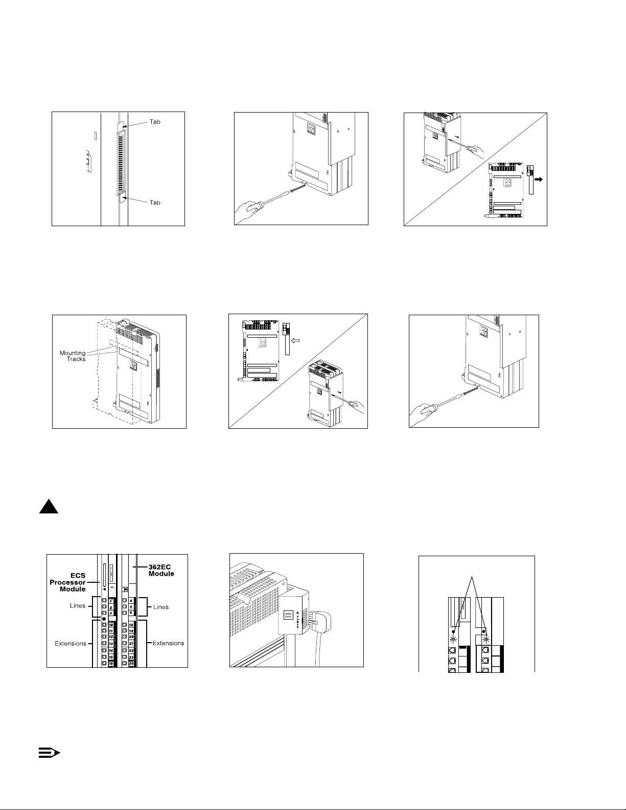
Remove the clear, plastic protector from the
connecto r on the r ight s id e of t he new 36 2EC
1
module by grasping the tabs on the ends of
the protector and lifting. If you are upgrading
from a stand-alone system, also remove the
protector from the wall-mounted PARTNER
Endeavor processor module.
A) Slide the second module off th e
4 5 6
PARTNER Endeavor processor module and
put it aside. B) Slide t he 362EC module onto
the PARTNER Endeavor processor module,
making s ure th e mount ing t racks i nterl ock, as
shown in the side view.
Caution: Do not force the module. If the
module does not insert easily, remove it,
clear any obstruction, and reinsert it.
A) Remove the #8 sheet metal screw from
2
the bottom of the wall-mounted module or
modules.
B) If you are upgrading an existing
stand-alone system, skip to Step 4B.
Attach the 2-Slot carrier to the top right side
of the two modules:
A) Align the carrier carefully and then push
firmly until the connector s on the modules
snap into the carrier.
B) Fasten the carrier to the modules using
the two #4 screws incl uded with the carrier.
If you are replacing the second module in a
3
two-slot carrier, remove the two #4 screws
holding the carrier in place and gently pull
the carrier off the modules.
Insert the 3 1/2" #8 screw into the bottom of
the modules. Tighten it until the mounting
tracks of the PARTNER Endeavor processor
module are flush aga inst the wall with a 3/8"
(1 cm.) gap between the wall and the rest of
the PARTNER Endeavor processor module.
Do not overtighten, the modules will warp.
A) Label the lines and extension jacks.
7 8
B) Connect the line and telephone cords to
the appropriate jacks on the new module.
C) Route each cord through the hook on the
front of its module. D) Connect the free end
of each ph one cor d to the mo dul a r wal l jack s
for system extensions.
Connect ETR and T/R combination
Press the power cord firmly into the power
jack on t he carrier. Plug the other en d of the
power cord into a properly grounded
three-prong wall outlet not controlled by a
switch.
devices to the last two ports on the
P A RTNER Endeavor processor or
362EC module.
Lights
ECS
Proc.
P F T
1
2
Check the green lights on the fronts of the
9
module s. If a singl e light is out, power down
the carrier, then power up the carrier. If both
lights are out, power down the carrier, reseat
both modules, then power up the carrier. If
the lights are still out, in the Continental U.S.,
call t he hotline at 1-800-721-7071. Ou tside
the Continental U.S., contact your Lucent
Technologies Representative or local
Authorized Dealer
.
362EC
Module
4
5
Page 3

PARTNER Endeavor Communications System Installation Instructions -
NOTE:
Line
Jacks
Extension
Jacks
Line
Jacks
Extension
Jacks
1
2
3
10
11
12
13
14
15
10
11
12
34
35
36
37
38
39
13
14
15
42
43
44
45
46
47
4
5
6
18
19
20
21
22
23
7
8
9
26
27
28
29
30
31
P F T
P F T
362EC
Module
362EC
Module
362EC
Module
362EC
Module
ECS
Proc.
COMBOCOMBO
COMBO
COMBO COMBO
MUSIC
ON
HOLD
Using a 2-Slot Carrier
IMPORTANT: To add a 362EC module to a PARTNER Endeavor system, the PARTNER Endeavor processor
module must already be mounted on the wall. If it is not, refer to the
instructions. Before starting, disconnect the power cord from the power jack in the carrier. Then follow the
instr uctions be low.
A) Move the carrier’s On/Off switch to "Off,"
1 2
and unplug the power cord from the wall
outlet. B) To remove the cover, loosen the
screw on lower front of the cover. C) Place
one hand on the hand le on the bottom front
of the co ver, an d place your other hand on
the top of the cover. Gently pull the cover up
and away from the carrier.
Before installing any modules, make sure the
clear, plast ic protect or has been removed
from the connector area on the rear of each
module . To remove the protector, grasp the
tabs on the ends of the protector and lift.
PARTNER Endeavor Installation Guide
362EC
COMBO
COMBO
COMBO
COMBO
COMBO
COMBO
A) Verify that the PARTNER Endeavor
3
processor module is in the center slot of the
carrier. In the other slots, from left to right,
install the 362EC modules. B) Align the
module carefully in the appropriate slot, and
push slowly but firmly in the center of th e
module until the connectors on the module
lock into place.
Processor
Module
for
!
CAUTION:
Caution: Do not force the module. If the
module does not insert easily, remove it,
clear any obstruction, and reinsert it
4
5
7
6
8
1
9
2
18
10
3
11
19
20
21
22
23
COMBO
24
COMBO
25
A) Labe l the line s an d ex tension jac k s.
4 5 6
B) Conn ect the line and telephone cords to
the appropriate jacks on the new module.
C) Route each cord through the hook on the
front of its module. D) Connect the free end
A) Plug the power cord into a properly
grounded three-prong wall outlet not
contro lle d by a switc h. B) Power up the
control unit by moving the On/Off switch to
the "On" position.
of each phone c ord to the modular wall jacks
for sys tem extens ions. E) Connect the free
end of ea ch telephone cord to the modular
connecting blocks for system extensions.
F) Gather the line and extension cords
13
26
12
14
27
E
X
10
T
15
28
E
11
34
N
S
29
12
I
35
42
O
N
30
13
36
S
43
31
14
37
44
COMBO
32
15
45
38
COMBO
COMBO
33
16
39
46
COMBO
COMBO
17
40
47
COMBO
COMBO
41
48
COMBO
49
Check the green lights on the fronts of the
modules. If a single light is out, power down
the carrier, then power up the carrier. If
multiple lights are out, power down the
carrier, reseat both modules, then power up
the carrier. If the lights are still out, in the
Continental U.S ., call the hotline at
1-800-721-7071. Outside the Continental
U.S., contact your Lucent Technologies
Representative or local Aut horized D ealer
hanging below the hook and twist tie or wire
wrap them . G) Place the bundle of wires in
the indentation on the bottom carrier.
.
Connect ETR and T/R combination
devices to the last two ports on the
PARTNER Endeavor processor or
362EC module.
A) To replace the carrier’s cover grasp it by
7
its upper edges an d hold it squarely over the
carrier. B) Place the cover over the modules
and make sure it fits firmly in place. If it does
not fit, make sure all modules are seated
properly. C) Tighten the screw on the lower
front of the cover.
Page 4

PARTNER Endeavor Communications System Installation Instructions Using a 5-Slot Carrier
IMPORTANT: To add a 362EC module to a PARTNER Endeavor system, using a 5-slot carrier, the PARTNER
Endeavor processor module and carrier must already be mounted on the wall. If it is not, refer to the
Endeavor Installation Guide
the 5-slot carrier.
for instructions. Follow the instructions below to install a 362EC expansion module in
PARTNER
 Loading...