

Page 1

DEFINITY® Extender
Rack Model 3000 &
Analog Switch Card Model 3100
System Administrator’s Guide
555-025-116
Comcode: 108373465
October 1998
Issue 1
Page 2

Copyright 1998, Lucent Technologies 555-025-116
All Rights Reserved Issue 1
Printed in Canada October 1998
Notice
Every effort was made to ensure that the information in this book was complete and accurate at
the time of printing. However, information is subject to change.
Your Responsibility for Your System’s Security
Toll fraud is the unauthorized use of your telecommunications system by an unauthorized
party, for example, persons other than your company’s employees, agents, subcontractors, or
persons working on your company’s behalf. Note that there may be a risk of toll fraud
associated with your telecommunications system and, if toll fraud occurs, it can result in
substantial additional charges for your telecommunications services.
You and your system manager are responsible for the security of your system, such as programming and configuring your equipment to prevent unauthorized use. The system manager is also
responsible for reading all installation, instruction, and system administration documents provided with this product in order to fully understand the features that can introduce risk of toll
fraud and the steps that can be taken to reduce that risk. Lucent Technologies does not warrant
that this product is immune from or will prevent unauthorized use of common-carrier
telecommunication services or facilities accessed through or connected to it. Lucent
Technologies will not be responsible for any charges that result from such unauthorized use.
Lucent Technologies Fraud Intervention
If you suspect that you are being victimized by toll fraud and you need technical support or
assistance, call the Lucent Technologies National Customer Care Center at 1 800 643-2353.
Page 3

Federal Communications Commission Statement
This equipment has been tested and found to comply with the limits for a Class A digital
device, pursuant to Part 15 of the FCC Rules. These limits are designed to provide reasonable
protection against harmful interference when the equipment is operated in a commercial
environment. This equipment generates, uses, and can radiate radio frequency energy and, if
not installed and used in accordance with the instruction manual, may cause harmful
interference to radio communications. However, there is no guarantee that interference will not
occur in a particular installation. For further FCC information, see "Customer Support
Information" below.
Industry Canada (IC) Interference Information
This digital apparatus does not exceed the Class A limits for radio noise emissions set out in the
radio interference regulations of the Canadian Department of Communications.
Le Présent Appareil Numérique n'émet pas de bruits radioélectriques dépassant les limites
applicables aux appareils numériques de la class A préscrites dans le reglement sur le
brouillage radioélectrique édicté par le ministère le ministère des Industrie Canada.
Trademarks
DEFINITY is a registered trademark of Lucent Technologies in the US and other countries.
Windows is a registered trademark of Microsoft Corporation
Page 4

Ordering Information
Call: Lucent Technologies Publications Center
Voice 1 800 457-1235 International Voice 317-322-6791
Fax 1 800 457-1764 International Fax 317-322-6699
Write: Lucent Technologies BCS Publications Center
2855 N. Franklin Road
Indianapolis, IN 46219
Order: Document No. 555-025-116
Comcode 108373465
Issue 1, October 1998
Support Telephone Number
In the continental US, Lucent Technologies provides a toll-free customer helpline 24 hours a
day. Call the Lucent Technologies Helpline at 1 800 242-2121 or your Lucent Technologies
authorized dealer if you need assistance when installing programming, or using your system.
Outside the continental US, contact your local Lucent Technologies representative.
Warranty
Lucent Technologies provides a limited warranty on this product. Refer to “Limited Warranty”
in “Customer Support Information.”
Page 5

Contents
Customer Support Information
Support Telephone Number.......................................................................vii
Security of Your System: Preventing Toll Fraud ....................................viii
FCC Regulations .........................................................................................x
Equipment Attachment Limitations...........................................................xii
Limited Warranty.....................................................................................xiii
Software End User License Agreement.................................................... xiv
About This Manual
Intended Audience....................................................................................xvi
Terms and Conventions............................................................................xvi
Conventions used in this Manual.............................................................xvii
How to Use This Manual........................................................................xviii
Issue 1 October 1998 i
Page 6

Contents
1. Product Overview
What a typical installation looks like....................................................... 1-4
DEFINITY Extender Model 3000 Rack Description.......................... 1-5
DEFINITY Extender Model 3100 Card Description........................... 1-6
The Switch Management Interface.......................................................... 1-7
2. Specifications
DEFINITY Extender Model 3000 Rack Specifications......................2-3
DEFINITY Extender Model 3100 Card Specifications....................... 2-4
3. Rack Installation
Lucent Supplied Equipment .................................................................... 3-2
Customer Supplied Equipment................................................................ 3-3
How to prepare the site for installation.................................................... 3-4
Electrical Requirements..................................................................3-5
Phone Line Requirements............................................................... 3-5
Safety Checklist.............................................................................. 3-5
Rack Backplane connectors..................................................................... 3-6
How to secure the Rack to a chassis........................................................ 3-8
How to wire the Rack to the PSTN and DEFINITY ECS.......................3-9
How to connect the Cards to the Data Network.....................................3-14
RS-232 DB-9 Connector Pinouts.................................................. 3-16
Before you Power Up the Rack.............................................................3-17
ii Issue 1 October 1998
Page 7

Contents
4. Installing Switch Cards
How to Install Switch Cards in the Rack..................................................4-3
5. Configuration
Configuration Steps..................................................................................5-3
How to Configure the Remote Module ....................................................5-4
How to connect to the ADMIN Port.........................................................5-5
How to install the Switch Management Interface.....................................5-5
How to Start the Switch Management Interface.......................................5-9
Password File Options............................................................................5-10
How to Open a User Password File........................................................5-11
How to Create a User Password File......................................................5-12
Initial Card Detection.............................................................................5-13
How to Change the Administrator Password..........................................5-15
User Access Code Overview..................................................................5-17
How to Add/Remove Users....................................................................5-19
How to Create/Delete User Groups........................................................5-20
How to Add/Remove Users from User Groups ......................................5-22
How to Assign User Groups to Cards.....................................................5-24
How to Upload Passwords to Cards.......................................................5-26
How to set the Switch Card Data Port....................................................5-28
How to Configure the Switch Management to the PCs COM port.........5-30
How to Access the Rack through Terminal Emulation ..........................5-31
Issue 1 October 1998 iii
Page 8

Contents
6. Troubleshooting
How to Identify Problems........................................................................ 6-3
Baseline Checklist ................................................................................... 6-3
General Troubleshooting Tips................................................................. 6-4
LED Light Sequences..................................................................... 6-5
Status Menu Information......................................................................... 6-9
PBX Flag/Make Busy options....................................................... 6-13
How a Remote User “Flags” a bad Switch Card................................... 6-14
Statistics Menu Information .................................................................. 6-15
Error Codes............................................................................................ 6-16
How to Troubleshoot Audio Problems.................................................. 6-19
How to Troubleshoot Connection Problems.......................................... 6-22
How to reset a forgotten Administrator Password................................. 6-33
7. Software Upgrades
How to check the software revisions of cards......................................... 7-2
How to Upgrade Switch Card Software .................................................. 7-3
How to Upgrade Software Using a Terminal program............................ 7-7
Upgrading the Remote Module..............................................................7-10
8. Glossary.............................................................................................. 8-2
iv Issue 1 October 1998
Page 9

Important Safety Instructions
The exclamation point in an equilateral trian gle
is intended to alert the user to the presence of
important operating and maintenance
(servicing) instructions in the literature
accompanying the product.
IMPORTANT SAFETY INSTRUCTIONS
To reduce the risk of fire, electrical shock, and injury to persons when
installing telephone equipment, always follow basic safety precautions
including:
•
Read and understand all instructions.
•
Follow all warnings and instructions marked on or packed with the
product.
•
Never install this unit or the telephone wiring for it during a lightning
storm.
•
Never install a telephone jack in a wet location unless the jack is
specifically designed for wet locations.
•
Never touch uninsulated telephone wires or terminals unless the
telephone wiring has been disconnected at the network interface.
•
Use caution when installing or modifying telephone lines.
Issue 1 October 1998
v
Page 10

Important Safety Instructions
•
Use only Lucent Technologies-manufactured DEFINITY Enterprise
Communications Server (ECS) circuit packs, carrier assemblies, and
power units in the DEFINITY ECS control unit.
•
Use only Lucent Technologies-recommended/approved DEFINITY
ECS accessories.
•
Do not install this product near water, for example, in a wet basement
location.
•
Do not overload wall outlets, as this can result in the ris k of fire or
electrical shock.
•
Do not attach the power supply cord to building s urfaces. Do not allow
anything to rest on the power cord. Do not locate this product where the
cord will be abused by persons walking on it.
•
Unplug the product from the wall outlet before cleaning. Use a damp
cloth for cleaning. Do not use cleaners or aerosol cleaners.
•
Do not operate the system if chemical gas leakage is suspected in the
area. Use telephones located in some other safe area to report the trouble.
WARNING:
DO NOT open the Rack Power Supply. There are no user
serviceable parts inside the unit. Only an authorized
technician should open the unit for required maintenance
or upgrading purposes.
SAVE THESE INSTRUCTIONS
vi Issue 1 October 1998
Page 11

Customer Support Information
Support Telephone Number
In the USA only
Lucent Technologies provides a toll-free customer
Helpline (1 800 242-2121) 24 hours a day. If you need
assistance when installing, programming, or using your
system, call the Helpline, or your Luce nt Technologies
authorized representative.
Outside the USA
If you need assistance when installing, programming, or
using your syst em, contact your Lucent Techno logies
authorized representative.
Issue 1 October 1998
vii
Page 12

Customer Support Information
Security of Your System: Preventing Toll Fraud
As a customer of a new telephone system, you should be
aware that there is an increasing problem of telephone
toll fraud. Telephone toll fraud can occur in many
forms, despite the numerous efforts of telephone
companies and telephone equipment manufacturers to
control it. Some individuals use electronic devices to
prevent or falsify records of these calls. Others charge
calls to someone else’s number by illegally using lost or
stolen calling cards, billing innocent parties, clipping on
to someone else’s line, or breaking into someone else’s
telephone equipment physically or electronically. In
certain instances, unauthorized individuals make
connections to the telephone network through the use of
remote access features.
Common carriers are required by law to collect their
tariffed charges. While these charges are fraudulent
charges made by persons with criminal intent,
applicable tariffs state that the customer of record is
responsible for payment of all long-distance or other
network charge s. Lucent Techno logies cannot be
responsible for such charges and will not make any
allowance or give any credit for charges that result from
unauthorized access.
viii Issue 1 October 1998
Page 13

Customer Support Information
Security of
Your
System:
Preventing
Toll Fraud
continued
To minimize the risk of unauthorized access to your
Lucent DEFINITY Extender Model 3000 and Model
3100:
When possible, restrict the off-network capability of offpremises callers, using calling restrictions, Facility
Restriction Levels, and Disallowed List capabilities.
When possible, block out-of-hours calling through
Time-of-Day Routing. Frequently monitor s ystem call
detail reports for quicker detection of any unauthorized
or abnormal calling patterns.
Limit Outcalling to persons on a need-to-have basis.
Lucent DEFINITY Extender Model 3000 and Model
3100 , through proper administration, can help you
reduce the risk of unauthorized persons gaining access
to the network. However, telephone numbers and
authorization codes can be compromised when
overheard in a public location, lost through theft of a
wallet or purse containing access information, or when
treated carelessly (writing codes on a piece of paper and
improperly discarding them).
Additionally, hackers may use a computer to dial an
access code and then publish the information to other
hackers. Substantial charges can accumulate quickly. It
is your responsibility to take appropriate steps to
implement the features properly, to evaluate and
administer the various restriction levels, and to protect
and carefully distribute access codes.
Under applicable tariffs, you will be responsible for
payment of toll charges. Lucent Technologies cannot be
responsible for such charges and will not make any
allowance or give any credit resulting from unauthorized
access.
Issue 1 October 1998
ix
Page 14

Customer Support Information
FCC Regulations
Lucent DEFINITY Extender Models 3000 and 3100
comply with Part 68 of the FCC rules. On the bottom of
the Rack is a label that contains the ringer equivalence
number (REN) for this equipment. If requested, this
information must be provided to the telephone company.
For Public Switch Network: Ringer Equivalence
Number (REN): 0.9B
The REN is used to determine the quantity of devices
which may be connected to the telephone line.
Excessive REN’s on the telephone line may re sult in t he
devices not ringing in response to an incoming call. In
most, but not all areas, the sum of the REN’s should not
exceed five. To be certain of the number of devices that
may be connected to the line, as determined by the total
REN’s contact the telephone company to determine the
maximum REN for the calling area.
If the Lucent DEFINITY Extender Model 3000 and
Model 3100 causes harm to the telephone network, the
telephone company will notify you in advance that
temporary discontinuance of service may be required. If
advance notice isn’t practical, the telephone company
will notify the customer as soon as possible. Also, you
will be advised of your right to file a complaint with the
FCC if you believe it is necessary.
The telephone company may make changes in its
facilities, equipment, operations, or procedures that
could affect the operation of the equipment. If this
happens, the telephone company will provide advance
notice in order for you to make the necessary
modifications in order to maintain uninterrupted service.
x Issue 1 October 1998
Page 15

Customer Support Information
FCC
Regulations
continued
For repair and warranty information, please contact:
Lucent Technologies Inc. at 1-800-242-2121.
If the trouble is causing harm to the telephone net work,
the telephone company may request you remove the
equipment from the network until the problem is
resolved.
The FCC prohibits customer provided terminal
equipment to be connected to a party line or to be used
in conjunction with coin telephone service. Lucent
DEFINITY Extender Model 3000 and Model 3100
have been registered for permissive operation at 10dBm.
Warning: This equipment has been tested and found to
comply with the limits for a Class A digital service,
pursuant to Part 15 of the FCC Rule s. These limits are
designed to provide reasonable protection against
harmful interference when the equipment is operated in
a commercial environment. This equipment generates,
uses, and can radiate radio frequency energy and, if not
installed and used in accordance with the instruction
manual, may cause harmful interference to radio
communications. Operations of this equipment in a
residential area is likely to cause har mful interference, in
which case the user will be required to correct the
interference at his own expense.
Issue 1 October 1998
xi
Page 16

Customer Support Information
Equipment Attachment Limitations
The Industry Canada label identifies certified equipment.
This certification means that the equipment meets certain
telecommunications network protective, operational and
safety requirements.
Industry Canada REN: 0.38
The department does not guarantee the equipment will
operate to the user’s satisfaction.
Before installing this equipment, users should ensure that
it is permissible to be connected to the o ff pre mise lines of
the local telecommunications company. The equipment
must also be installed using an acceptable method of
connection. In some cases, the company’s inside wiring
associated with a single line individual service may be
extended by means of a certified connector assembly
(telephone extension cord). The customer should be aware
that compliance with the above conditio ns may not prevent
degradation of service in some situations.
Repairs to certified equipment should be made by an
authorized Canadian maintenance facility designated by
the supplier. Any repairs or alterations made by the user
to this equipment, or equipment malfunctions, may give
the telecommunications company cause to request the user
to disconnect the equipment.
Users should ensure for their own protection that the
electrical ground connections of the power utility,
telephone lines and internal metallic water pipe system, if
present, are connected together. This precaution may be
particularly important in rural areas. Caution: Users
should not attempt to make such co nnections themselves,
but should contact the appropriate electric inspection
authority, or electrician, as appropriate.
xii Issue 1 October 1998
Page 17

Customer Support Information
Limited Warranty
Lucent Technologies Inc. warrants this equipment to be
free of defects in materials and workmanship for a period
of one year from date of shipment. All defects within thi s
time will be repaired without charge upon return of the
unit to the factory.
This warranty is null and void if the manufacturer
determines that any modifications have been made to the
unit or the unit has been subjected to physical or
electrical stress.
This warranty covers parts and labor only, and does not
include shipping costs, travel expenses or travel time.
Installation of the equipment is the sole responsibili ty of
the purchaser. The manufacturer, its agents or
distributors accept no responsibility for malfunction or
damage caused by improper treatment or connection of
the unit.
The manufacturer, its agents, or distributors are not liable
for any losses incurred through use or malfunction of the
equipment or any losses or damages incurred by the use
of the equipment in any means whatsoever.
This warranty is limited to the repair of the eq uipment to
its normal functioning capability.
This warranty is complete as stated and all other
warranties, expressed or implied, are invalid.
The Model 3000 and the Model 3100 should only be
installed by qualified personnel. No user serviceable parts
are contained within the units. Installation or
programming should not begin prior to review of all
chapters of this manual.
Issue 1 October 1998
xiii
Page 18

Customer Support Information
Software End User License Agreement
BY LOADING OR USING THE SOFTWARE, YOU
ARE CONSENTING TO BE BOUND BY THIS
AGREEMENT.
DISCLAIMER OF WARRANTY.
SOFTWARE IS PROVIDED ON AN "AS IS" BASIS,
WITHOUT WARRANTY OR REPRESENTATION
OF ANY KIND, EXPRESS OR IMPLIED. LUCENT
TECHNOLOGIES EXPRESSLY DISCLAIMS AND
EXCLUDES THE WARRANTIES OF
MERCHANTABILITY, FITNESS FOR A
PARTICULAR PURPOSE, AND NONINFRINGEMENT. THE ENTIRE RISK AS
TO THE QUALITY AND PERFORMANCE OF THE
SOFTWARE IS BORNE BY YOU. SHOULD THE
SOFTWARE FAIL, YOU AND NOT LUCENT
TECHNOLOGIES ASSUME THE ENTIRE RISK OF
ANY COSTS AND DAMAGES THAT MAY
RESULT.
LUCENT TECHNOLOGIES HAS NO OBLIGATION
TO SUPPORT THE SOFTWARE, AND YOU AGREE
NOT TO SEEK ANY SUCH SUPPORT FROM
LUCENT TECHNOLOGIES. THIS DISCLAIMER OF
WARRANTY CONSTITUTES AN ESSENTIAL
PART OF THE AGREEMENT. SOME
JURISDICTIONS DO NOT ALLOW EXCLUSIONS
OF AN IMPLIED WARRANTY, SO THIS
DISCLAIMER MAY NOT APPLY TO YOU, AND
YOU MAY HAVE OTHER LEGAL RIGHTS THAT
VARY BY JURISDICTION.
xiv Issue 1 October 1998
Page 19

Customer Support Information
Software
End User
License
Agreement
continued
LIMITATION OF LIABILITY.
RECOGNIZING THAT YOUR RIGHT TO USE THE
SOFTWARE IS PROVIDED FREE OF CHARGE,
YOU AGREE THAT IT IS FAIR, REASONABLE,
AND NOT UNCONSCIONABLE TO RELEASE
LUCENT TECHNOLOGIES AND OTHERS FROM
ANY LIABILITY ARISING IN CONNECTION
WITH THE SOFTWARE. UNDER NO
CIRCUMSTANCES AND UNDER
NO LEGAL THEORY (INCLUDING WITHOUT
LIMITATION TORT INCLUDING NEGLIGENCE,
CONTRACT, STRICT LIABILITY, OR
OTHERWISE), SHALL LUCENT TECHNOLOGIES
OR ITS AFFILIATES OR SUPPLIERS (OR THEIR
RESPECTIVE EMPLOYEES OR AGENTS) BE
LIABLE TO YOU OR ANY OTHER PERSON FOR
DAMAGES OF ANY KIND OR CHARACTER,
WHETHER DIRECT, INDIRECT, SPECIAL,
INCIDENTAL, OR CONSEQUENTIAL,
INCLUDING WITHOUT LIMITATION DAMAGES
FOR LOSS OF GOODWILL, WORK STOPPAGE,
COMPUTER FAILURE OR MALFUNCTION, OR
ANY AND ALL OTHER COMMERCIAL
DAMAGES OR LOSSES, EVEN IF LUCENT
TECHNOLOGIES HAS BEEN INFORMED OF THE
POSSIBILITY OF SUCH DAMAGES.
THIS LIMITATION OF LIABILITY SHALL NOT
APPLY TO LIABILITY FOR DEATH OR BODILY
INJURY TO THE EXTENT APPLICABLE LAW
PROHIBITS SUCH LIMITATION. FURTHERMORE,
SOME JURISDICTIONS DO NOT ALLOW
THE EXCLUSION OR LIMITATION OF
INCIDENTAL OR CONSEQUENTIAL DAMAGES,
SO THIS LIMITATION AND EXCLUSION MAY
NOT APPLY TO YOU.
Issue 1 October 1998
xv
Page 20

About This Manual
Intended Audience
This manual is intended to help with the insta llation, configuration, and
maintenance of the Lucent DEFINITY Extender Model 3000 and Model
3100. It is intended for use by anyone needing such information, including
system administrators, support personnel, and technicians.
Terms and Conventions
The Lucent DEFINITY Extender Model 3000 is henceforth referred to as
the Rack.
The Lucent DEFINITY Extender Model 3100 is henceforth referred to as
the Analog Switch Card.
Switch Cards is a generic term for additional cards that can be installed in the
Rack.
Lucent DEFINITY ECS is henceforth referred to as DEFINITY ECS, or as
the system.
xvi Issue 1 October 1998
Page 21

About This Manual
Conventions used in this Manual
Certain type fonts and styles are used as visual cues to help you rapidly
understand the information presented:
Example Purpose
NOTE: Do not recycle old
passwords.
Enter the new password and
click Change.
Example: First Name Text that is underlined provides
Italics indicate a note to add
additional reference information.
Text in bold print is used to
indicate a menu option or
acceptance block within the
Switch Management Interface
software.
an example of the subject matter.
Issue 1 October 1998
xvii
Page 22

About This Manual
How to Use This Manual
The manual is divided into eight chapters as follows.
Chapter
Number
1 Product Overview Provides a product overview,
2 Specifications Lists all appropriate electrical,
3 Rack Installation Provides information for the
Title Description
Rack description and
information on Analog Switch
Cards.
communications, and data
specifications.
installation of the Rack. It
includes pre-installation
checklists and connectivity
information.
xviii Issue 1 October 1998
Page 23
About This Manual
How to use this Manual continued
Chapter
Number
4 Installing Switch
Cards
5 Configuration Provides information for configuring
6 Troubleshooting Provides step-by-step task lists to
7 Software Upgrades Provides instructions for updating the
Title Description
Explains the steps necessary to
quickly install new Analog Switch
Cards in the Rac k.
the Rack and all Switch Cards to
communicate with the appropriate
remote modules, using Lucent
Technologies Switch Management
Interface or a PC running a terminal
emulation program.
determine operational errors,
communication errors, and functional
problems with the Rack or individual
Switch Cards.
software to the latest release level.
8 Glossary Provides a list of terms that are used
in the operation or setup of the
Lucent Technologies product line.
Issue 1 October 1998
xix
Page 24

About This Manual
This page intentionally left blank.
xx Issue 1 October 1998
Page 25

Product Overview
Chapter Contents
Subject Page
Product over view 1-2
Rack description 1-5
Card description 1-6
Switch Management
Interface description
1-7
Issue 1 October 1998 1-1
Page 26

Product Overview
Product Overview
Introduction
Product
Summary
This chapter provides a product overview that includes:
q
Product summary
q
Product descr i ptions
The DEFINITY Extender Model 3000 is a high-density
switch-side device that connects to the DEFINITY ECS’
digital line interface. The Rack can be configured with up
to 12 Switch Cards, which are sold separately.
The Rack can be configured with up to 12 Switch Cards,
in any combination Model 3100 Analog Switch Cards, or
the Model 3200 ISDN Switch Cards.
Note: The Model 3200 ISDN Switch Card is not yet
available.
Analog Switch Cards extend one DEFINITY ECS
terminal per card for a total of 12 users per Rack, while the
ISDN Switch Cards can extend two DEFINITY ECS
terminals per card for a total of up to 24 users per Rack.
To use the Switch Cards to extend a terminal, the remote
user must have an accompanying remote module extender
(sold separately). See Table 1-1, next page, for the remote
module required to connect to the corresponding Switch
Card.
1-2 Issue 1 October 1998
Page 27
Product Overview
Description Switch Card
Model
Remote Module
Model
Number of
simultaneous
users per card
Analog
3100 1101 1
Extenders
ISDN Extenders 3200 2101 2
Table 1-1. Remote Module Compatibility
Note: Switch Cards and Remote Modules are sold separately from the Rack.
Contact your Lucent Technologies rep resentative for information.
Each remote user is assigned and can communicate with any one or all of the
Switch Cards. The administrator manages remote access to the cards via the
Switch Management Interface.
Most features of the system are maintained for transparent functionality.
Features include;
q
ability to place and receive calls,
q
extension-to-extension dialing,
q
speed dial,
q
transfer calls,
q
conference calls,
q
access to voicemail,
q
auto-attendant,
q
and utilization of ACD systems and call accounting software.
Issue 1 October 1998
1-3
Page 28
Product Overview
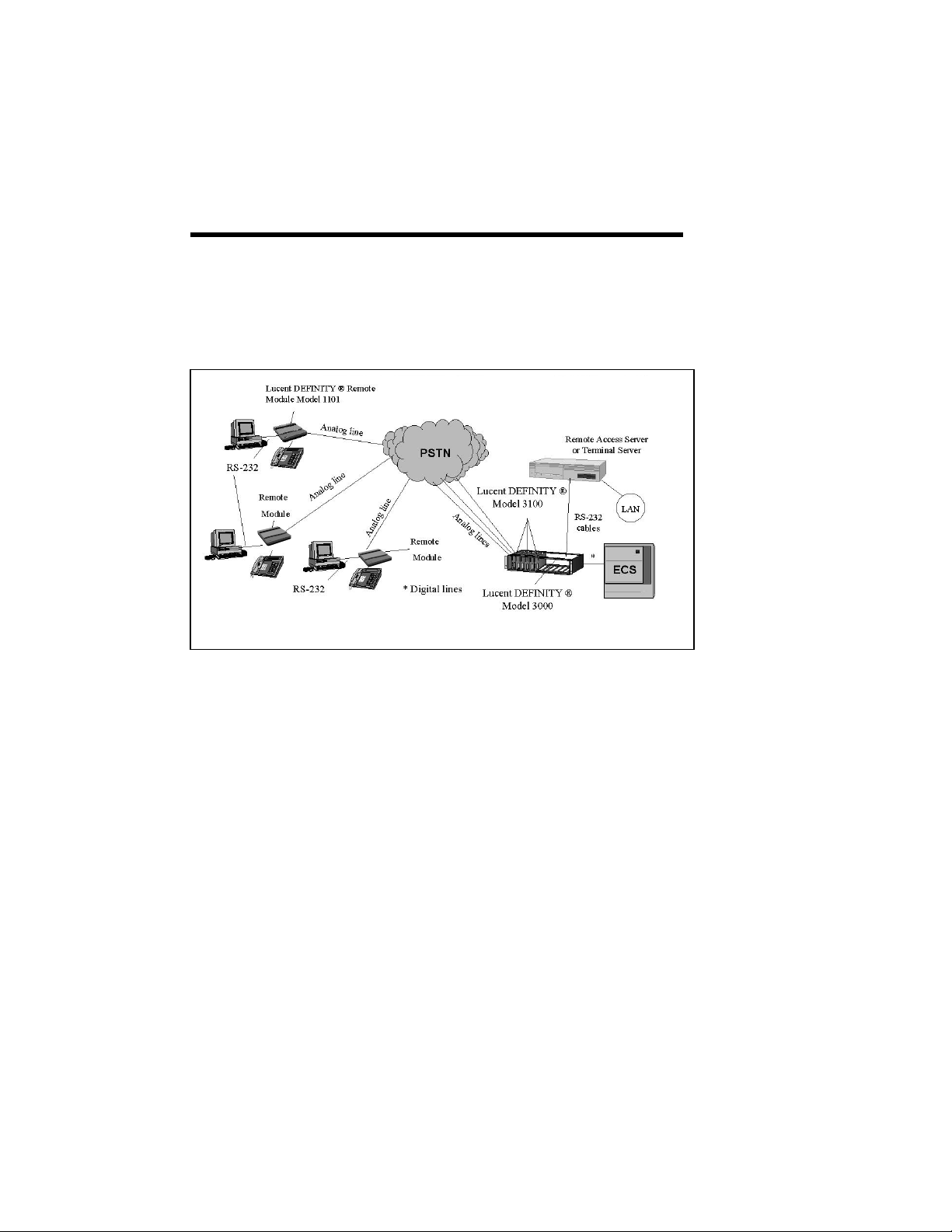
What a typical installation looks like
Typical
installation
The Rack is co-located with the DEFINITY ECS. A
remote module is required to connect to the terminal at
the off-premise location(s). Figure 1.1 below,
illustrates a typical installation.
Figure 1.1 Typical Installation
Figure 1.1. Typical Installation
1-4 Issue 1 October 1998
Page 29

Product Overview
DEFINITY Extender Model 3000 Rack Description
Description
Phone line
Backplane
Data
Connection
Configuration
DEFINITY Extender Model 3000 is a central site device
installed at the DEFINITY ECS location. It is mounted to a
chassis in the equipment room and powered by an internal
120V power supply. The Rack accommodates up to 12
Switch Cards allowing 12 remote users (using Model 3100
Switch Cards) access to the system.
The Rack requires Switch Cards to be installed to provide
voice and data connectivity using standard telephone lines.
All connections, internal and external, are wired through
the Rack backplane. The DEFINITY ECS and Public
Switched Telephone Network (PSTN) connections are
wired using four 50-pin connectors installed on the
backplane.
The data connection acts as a simple null modem cable
extending the corporate data network to the remote
location. The backplane provides two data ports (COMA,
COMB) per Switch Card, allowing connection to the
corporate Remote Access Server or Terminal Server.
Example: The COM ports for the Switch Card in Rack slot
0 are labeled as follows:
q
COM0A
q
COM0B (only used with Model 3200
Switch Cards)
The administrator can configure, troubleshoot and update
every Switch Card in the Rack from a single ADMIN port,
using a Wind ows based ma nagement software package.
See the Switch Management Interface section on page 1-7
for more information
Note: Switch cards can also be configured individually by
attaching a VT100 compatible terminal to COMA of each
Switch Card.
Issue 1 October 1998
1-5
Page 30

Product Overview
DEFINITY Extender Model 3100 Card Description
Description
Remote User
Functions
Voice/Data
connectivity
Extender
Features
The Analog Switch Card is a PCB (Printed Circuit
Board) with circuitry that provides functionality similar
to the Model 1100 Switch Module.
Functions include:
•
Access to all features of the system.
•
Data connectivity via a Terminal Server or Remote
Access Server.
Each Model 3100 Switch Card communicates with one
Remote Module Model 1101 (sold separately) and can
extend one Lucent terminal.
The system is fully transparent to the remote user and
retains access to most of the features and functions of
the digital phone and telephone switch.
Voice and data connectivity is multiplexed over a single
analog phone line.
C.O.D. Call on Demand: Can reduce long distance
line cost’s by establishing a connection only when a call
is detected, or when there is activity on the remote
phone.
Dialback: Enables the switch module to disconnect,
and then dial back to the remote module after a
connection has been successfully completed. After
dialback, connection to the remote mod ule is from the
system. Using DEFINITY ECS facilities may reduce
the cost of the connection.
1-6 Issue 1 October 1998
Page 31

Product Overview
The Switch Management Interface
Introduction
The ADMIN
Port
Upgrade
process for 3100
Switch Cards
The DEFINITY Extender Switch Management Interface
is a Windows-based software package that provides a
user-friendly interface for the DEFINITY Extender
system administrator.
The Switch Management Interface, when connected
through to the ADMIN port of the Rack, is used for the
configuration, status, troubleshooting, monitoring, and
software upgrades for all 12 Switch Cards
simultaneously.
The Switch Management Interface software is year 2000
compliant, and requires Windows 95, or Windows NT
4.0 or higher to operate properly. See Customer
Supplied Equipment in Chapter 3, for PC requirements.
Switch Cards are configured using the AD MIN port.
The port is connected to a PC via an RS-232 connector.
In addition, Card “0” must contain the Switch Card
(3100 or 3200) with the latest revision of software to
utilize all features of the Switch Management Interface.
See How to Connect to the ADMIN port in Chapter 5 for
more information.
The Switch Management Interface is used for upgrading
the software for the Model 3100 Switch Cards. The
administrator can upgrade a single card or multiple cards
simultaneously.
Note: You can upgrade the Model 1101 Remote Module
from the Switch Card over the analog connection. See
Upgrading the Remote Module in Chapter 7 for more
information.
Issue 1 October 1998
1-7
Page 32

Product Overview
This page intentionally left blank.
1-8 Issue 1 October 1998
Page 33

Specifications
Chapter Contents
Subject Page
Introduction 2-2
Rack Specifications 2-3
Card Specifications 2-4
Issue 1 October 1998 2-1
Page 34

Specifications
Specifications
Introduction
Mi n imu m Dat a
Rate
Transmission
Line
Conditions
NOTE: Specifications are subject to change without notice as technological
or manufacturing changes warrant.
This chapter contains information on specific electrical
and mechanical parameters. It is provided as a reference
on the design of the Rack and cards.
The Switch Cards within the Rack operate on a standard
analog line. A minimum data rate of 14.4 Kbps is
required for voice functionality. The recommended data
rate is 19.2 Kbps. Contact the local telephone company
for special conditioning if these rates cannot be
maintained.
The DEFINITY Extender Model 3000 and Model 3100
have been tested under transmission line conditions
specified in TSB-37A. The specification calls for
checking modem operation over the equivalent of 95% of
the identified analog line types in North America. This
means that the DEFINITY Extender Model 3000 and
Model 3100 should operate properly over nearly all
telephone line conditions. However, the actual connect
rate will vary based on the quality of the telephone line.
2-2 Issue 1 October 1998
Page 35

Specifications
DEFINITY Extender Model 3000 Rack Specifications
Item Specification Reference Information
Approvals NRTL/C, FCC, Parts 15
and 68, Class A, Industry
Canada
Size 12 card frame 19”W x 5.25”H x 10”D
(484mm x 133mm x
255mm)
Capacity 12 Switch Cards
Number of users
Power
Requirements
User Data Port RS-232 2 ports per card
Administrative
port
PSTN connectors T wo 50-pin male
ECS Digital port
connectors
Electrical
Requirements
Environmental
Requirements
12 (using DEFINITY
Model 3100 Cards)
One internal 120V
regulated power supply,
which provides 12VDC
and 5VDC.
RS-232 serial (DB-9,
female) connector
connectors
Two 50-pin male
connectors
120 VAC 60 Hz.
Ambient Temperature:
0 – 55 Degrees C
Relative Humidity:
0 – 95%
24 (using DEFINITY
Model 3200 Cards),
future use only.
5 Volts at 600 mA per
interface card
12 Volts at 100 mA per
interface card
1 port for entire Rack
One connector per six
Switch Cards.
One connector per six
Switch Cards
Provide adequate
ventilation.
Table 2-1. Rack Specifications
Issue 1 October 1998
2-3
Page 36

Specifications
DEFINITY Extender Model 3100 Card Specifications
Specification Description
Approvals NRTL/C, FCC, Parts 15 and 68, Class A,
Industry Canada
Communication
Modem Connect Rates 14.4, 16.8, 19.2, 21.6, 24.0, 26.4, 28.8,
31.2, 33.6Kbps
Voice Compression G.723.1 (6.3Kbps)
Data Type Ro ckwell V.34 internal modem
Data Impedance 600 Ohms
Data Tx Level –10 dBm (+1 dBm/–3 dBm)
Data Rx Sensitivity – 9 to - 43 dBm
User Data Port
Data Type RS-232, using COMA on Rack.
Data Rate Settings 2.4 Kbps, 4.8 Kbps, 9.6 Kbps, 19.2 Kbps,
38.4 Kbps, 57.6Kbps, 115.2 Kbps
Parity Setting N one, Even, Odd
Data Bits Setting 7, 8
Stop Bits Setting 1 o r 2
Table 2-2. Analog Switch Card Specifications
2-4 Issue 1 October 1998
Page 37

Rack Installation
Chapter Contents
Subject Page
Introduction 3-2
Lucent Supplied
Equipment
Customer Supplied
Equipment
How to Prepare Site 3-4
Rack Backplane 3-6
How to secure the Rack 3-8
How to wire the Rack 3-9
How to connect the Switch
Card to the Data Network
Before you Power Up the
Rack
3-2
3-3
3-14
3-17
Issue 1 October 1998 3-1
Page 38

Rack Installation
Rack Installation
Introduction
This chapter provides the following infor mation:
q
Pre-installation requirements
q
How to install the Rack hardware
q
How to wire the Rack backplane for connections to the
PSTN and DEFINITY ECS.
q
Complete power-up sequence
Lucent Supplied Equipment
DEFINITY
Extender Model
3000
DEFINITY
Extender Model
3100
(sold separately
from Rack
Operational
Considerations
q
One twelve slot Rack mountable chassis
q
One power cord
q
One System Administrator’s Guide
q
Switch Management Interface software (2 disks)
q
One Analog Switch Card
q
One Quick Installation Guid e
q
The Rack is to be used with DEFINITY ECS
Version 3, Release 3 or later.
q
Order a separate central office (CO) line at each
remote module location.
q
Each Switch Card will need a digital port
(extension) from the DEFINITY ECS, and an
analog line from the (CO) or the DEFINITY ECS.
q
Be sure that the DEFINITY ECS digital port to
which the Switch Card is connected is
programmed correctly for the telephone type
being used at the remote location.
q
Remote Modules, desksets and co mmunication
line cords are NOT supplied with this syste m.
q
Use two-wire digital display phones only.
3-2 Issue 1 October 1998
Page 39

Rack Installation
Customer Supplied Equipment
NOTE: DEFINITY ECS telephones are not supplied with either the Switch
Cards or the remote modules. These items must be ordered separately.
Contact your Lucent Technologies rep resentative for information.
You must supply the following for installation:
q
DEFINITY ECS two-wire, 24-port TN-2224 circuit pack or the older 16
port TN2181.
q
Any additional DEFINITY ECS circuit packs needed (see the DEFINITY
Communications System Generic 3, Installation for Single-Carrier
Cabinets manual, document #555-230-894, comcode #107595423, for
further information).
q
An adapter to convert to 120 VAC if you are connecting the Rack to a
240 VAC outlet.
q
Power and central office line suppresser. Lucent Technologies
recommends the 147C AC/CO Line Surge Protector (#8310-006).
Contact your Lucent T ec hnolo gie s rep r esenta ti ve fo r or de ri ng
instructions.
q
Four 50-pin female connectors (two connectors for every six Switch
cards)
q
A computer for installing and using the Switch Management Interface.
Minimum requirements as shown in Table 3.0 below:
Minimum
Processor 486 DX2 66MHZ
RAM 16MB
Operating
Systems
WIN 95, WIN 98, or
Windows NT 4.0
Disk Drive 3 ½ Floppy Disk
Free Disk
6.0 MB
Space
Table 3-0. Minimum PC Requirements
Issue 1 October 1998
3-3
Page 40

Rack Installation
How to prepare the site for installation
q
The maximum length of cable between the Rack
Location
Checklist
and the DEFINITY ECS is 500 ft (150 meters).
q
The Rack’s power supply and cabling should be
installed away from high power/high RF noise
devices such as computers, fans, fluorescent ballast,
power supplies, etc.
q
Use good wiring practices. Do not run wires over
fluorescent lights, computers, air conditioners, etc.
as this can introduce noise to the modems.
q
The Rack must be installed in a secure location.
Unauthorized access to the Rack could lead to toll
fraud.
Reference
Document
Installation
Requirements
DEFINITY ECS
Checklist
Refer to the DEFINITY ECS Communications System
Generic 3, Installation for Single-Carrier Cabinets
manual, document #555-230-894, comcode
#107595423, for further information.
q
Four 25-pair cables with female connectors for each
Rack
q
One DCP line for each Model 3100 Switch Card
q
One analog line for each Model 3100 Switch Card
q
110-blocks sufficient for the installation
q
Additional cables sufficient for the DCP and analog
lines.
q
Install 110-blocks
q
Connect the DCP lines from the DEFINITY ECS to
the wall-field.
q
Connect two of the 25-pair cables to the Rack
digital ports (P106 and P108)
q
Cross-connect the Rack digital ports to the
DEFINITY DCP lines (see Tables 3-2 and 3-3 in
this Chapter)
q
Connect the analog lines from the PSTN or
DEFINITY ECS to the wall-field.
q
Connect the two remaining 25-pair cables to the
Rack PSTN ports (P107 and P105).
q
Cross-connect the Rack PSTN ports to the analog
lines (see Tables 3-4 and 3-5 in this Chapter)
3-4 Issue 1 October 1998
Page 41

Rack Installation
Electrical Requirements
Phone Line Requirements
Safety Checklist
The system has been designed to operate from 120 VAC
60 Hz. Power should not be applied to the Rack until
specified in the installation procedures.
Standard analog lines from the CO, or analog lines off
circuit packs of the DEFINITY ECS, (TN746B).
❐ Never install telephone wiring during a lightning
storm.
❐ Never install telephone jacks in wet locations unles s
the jack is specifically designed for wet locations.
❐ Never touch non-insulated telephone wires or
terminals unless the telephone line has been
disconnected at the network interface.
Issue 1 October 1998
3-5
Page 42

Rack Installation
Rack Backplane connectors
Introduction
Figure 3.1, shown below, illustrates the Rack backplane. All
connectors, both RS-232 and 50-pin, are labeled. Detail “A”
details the COM ports for all Switch Cards. Refer to Table
3-1, on the next page for connector descriptions.
Note: COMB ports are not used with Model 3100 Switch
Cards.
Figure 3. 1. Rack Backplane
3-6 Issue 1 October 1998
Page 43

Rack Installation
Connector
ID/Label
ADMIN PORT RS-232, DB9 female
connector used to interface
with the Switch Management
Interface, running on a PC.
CARDs 0-11 Switch Card slots At the top of the
DIGITAL PORTS
P106
PSTN
P105
DIGITAL PORTS
P108
PSTN
P107
50-pin male connector from
DEFINITY ECS Digital
ports to Switch Cards in slots
0-5 (see Table 3-2, for
pinouts and wiring details)
50-pin male connector from
PSTN to Switch Cards in
slots 0-5 (see Table 3-4, for
pinouts and wiring details)
50-pin male connector from
DEFINITY ECS Digital
ports to Switch Cards in slots
6-11 (see Table 3-3, for
pinouts and wiring details)
50-pin male connector from
PSTN to Switch Cards in
slots 6-11 (see Table 3-5, for
pinouts and wiring details)
Description Label Placement
backplane, above the
connector pins.
At the top of the 50 pin
connector.
At the top of the 50 pin
connector
At the top of the 50 pin
connector
At the top of the 50 pin
connector
COMA ports 0-11 RS-232 DB9 female
connector used for Data.
Each Analog Switch Card is
provided with one COM
port.
COMB ports 0-11 Not used at this time.
Table 3-1. Backplane connectors defined
Above connector.
(Lower of two DB-9
connectors)
Issue 1 October 1998
3-7
Page 44

Rack Installation
How to secure the Rack to a chassis
Introduction
Procedure
The following procedure explains the steps necessary to
secure the Rack to an existing chassis.
1. Position the Model 3000 Rack so the mounting “ears”
of the Rack frame are aligned with the mounting holes
of the chassis. (see Figure 3.2 below)
2. Secure the Rack with mounting hardware (4 screws)
provided.
Figure 3.2 Rack Mounting
3-8 Issue 1 October 1998
Figure 3.2. Rack Mounting
Page 45

Rack Installation
How to wire the Rack to the PSTN and DEFINITY ECS
Introduction
Definitions
The following procedure provid es wiring information to
connect the mounted Rack via the backplane connectors
to the PSTN and to the digital ports on the DEFINITY
ECS. (see Tables 3-2, 3-3, 3-4 and 3-5 for pinouts and
wiring details)
Twisted Pair: Two insulated copper wires twisted around
each other to reduce interference with other electrical
sources. Numbers refer to pin numbers on the 50 pin
female connector.
Tip wire: The negative conductor in a telepho ne cable
pair.
Ring wire: The positive conductor in a telepho ne cable
pair.
Port 1, Port 2: Connections from Switch Cards to
DEFINITY ECS digital port.
Note: Only Port 1 is used for Model 3100 Analog Switch
Cards. Port 2 (future use) is for Model 3200 ISDN Switch
Cards which extends two digital ports per card for a
maximum of 24 remote users per Rack.
Card: Identifies the Switch Cards in the Rack
(0 through 11)
Procedure
1. Wire the Rack to the DEFINITY ECS using two
50-pin female connectors. Use the tables provided in
this Chapter for specific twisted pair connections:
q
P106, (Cards 0-5) Table 3-2
q
P108, (Cards 6-11) Table 3-3
2. Wire the Rack to the PSTN using two 50-pin female
connectors. Use the tables provided in this Chapter
for specific twisted pair connections:
q
P105, (Cards 0-5) Table 3-4
q
P107, (Cards 6-11) Table 3-5
Issue 1 October 1998
3-9
Page 46

Rack Installation
Connections from DEFINITY ECS Digital port to Rack (Cards 0-5)
Twisted
Pair
Wire Port Card Wire Port Card
1Tip10 13Tip13
26 Ring 1 0 38 Ring 1 3
2Tip20 14Tip23
27 Ring 2 0 39 Ring 2 3
5Tip11 17Tip14
30 Ring 1 1 42 Ring 1 4
6Tip21 18Tip24
31 Ring 2 1 43 Ring 2 4
9Tip12 21Tip15
34 Ring 1 2 46 Ring 1 5
10 Tip 2 2 22 Tip 2 5
35 Ring 2 2 47 Ring 2 5
Rack
Termination
Table 3-2. Connector P106
Note: Italics represent connections for future
Model 3200 (ISDN Switch Cards) only.
Twisted
Pair
Rack
Termination
3-10 Issue 1 October 1998
Page 47

Rack Installation
Connections from DEFINITY ECS Digital port to Rack (Cards 6-11)
Twisted
Pair
Wire Port Card Wire Port Card
1Tip16 13Tip19
26 Ring 1 6 38 Ring 1 9
2Tip26 14Tip29
27 Ring 2 6 39 Ring 2 9
5 T ip 1 7 17 Tip 1 10
30 Ring 1 7 42 Ring 1 10
6 Tip 2 7 18 Tip 2 10
31 Ring 2 7 43 Ring 2 10
9 T ip 1 8 21 Tip 1 11
34 Ring 1 8 46 Ring 1 11
10 Tip 2 8 22 Tip 2 11
35 Ring 2 8 47 Ring 2 11
Rack
Termination
Table 3-3. Connector P108
Note: Italics represent connections for future
Model 3200 (ISDN Switch Cards) only
Twisted
Pair
Rack
Termination
Issue 1 October 1998
3-11
Page 48

Rack Installation
Connections from PSTN to backplane (slots 0-5)
Twisted
Pair
1 Tip 0 13 Tip 3
26 Ring 0 38 Ring 3
5 Tip 1 17 Tip 4
30 Ring 1 42 Ring 4
9 Tip 2 21 Tip 5
34 Ring 2 46 Ring 5
Table 3-4. Connector P105
Rack
Termination
Wire Card Wire Card
Twisted
Pair
Rack
Termination
3-12 Issue 1 October 1998
Page 49

Rack Installation
Connections from PSTN to backplane (slots 6-11)
Twisted
Pair
1 Tip 6 13 Tip 9
26 Ring 6 38 Ring 9
5 Tip 7 17 Tip 10
30 Ring 7 42 Ring 10
9 Tip 8 21 Tip 11
34 Ring 8 46 Ring 11
Table 3-5. Connector P107
Rack
Termination
Wire Card Wire Card
Twisted
Pair
Rack
Termination
Issue 1 October 1998
3-13
Page 50

Rack Installation
How to connect the Cards to the Data Network
Introduction
Each Switch Card installed in the Rack can be connected to
the corporate LAN via a Remote Access Server or Terminal
Server.
A standard RS-232 DB9 male connector plugs into the
appropriate COMA port (COMB not used for Model 3100
Analog Cards) on the Rack backplane. Each Switch Card
acts as a DCE. When a remote module connects to a Switch
Card, the pair extends the RS-232 port to the remote
location.
Note: The connections are shown in Figure 3.3. (see Table
3-6 in this Chapter, for more detailed information about RS232 DB-9 pinouts)
Figure 3.3. Data Port connectors (on the Rack Backplane)
3-14 Issue 1 October 1998
Page 51

Rack Installation
How to connect the Cards to the Data Network
continued
q
Connect your Personal Computer (COM port)
Remote PC
Connectivity
or data terminal to the RS-232 port on the
remote module.
q
A 9-pin straight through cable will work for
many Personal Computers. An adapter is
needed if the PC does not have a 9-pin
connector.
NOTE: The RS-232 cable length must not exceed
50 feet.
PC COM port settings
Before data connectivity is ope rational, you must
make sure that the data settings on the Switch
Card, remote module, remote PC, and RAS or
Terminal Server all match.
Issue 1 October 1998
3-15
Page 52

Rack Installation
RS-232 DB-9 Connector Pinouts
Introduction
PIN EIA
1 RLSD Received Line
2 RD Received Data at
3 SD Transmitted Data
4 DTR DTE Ready Input
5 SG Signal Ground Common
6 DSR DCE Ready Output
7 RTS Request to Send Input
8 CTS Clear to Send Output
9 RI No Connection NA
RS-232
Terminology
Table 3-6, shown below, lists each pin within the RS-232
connector with the signal description and direction of data
flow.
DESCRIPTION DIRECTION
DESIG
Output
Signal Detector
Output
DTE
Input
from DTE
Table 3-6. RS-232 Cable Pinouts
EIA: Electronics Industry Association
DTE: Data Terminal Equipment
DCE: Data Communications Equipment.
Note: The interface is specified by EIA/TIA 574. The term RS-232 refers to
the older 25-pin specification. RS-232 is used in this manual because of the
common use of the term for serial interfaces.
3-16 Issue 1 October 1998
Page 53

Rack Installation
Before you Power Up the Rack
Introduction
Rack
Checklist
Safety
Checklist
This procedure will detail the necessary steps to perform
BEFORE bringing the loaded Rack online.
q
The Rack is secured properly.
q
The power cord is connected.
q
Rack position “Card 0” contains the late st Switch Card
(Model 3100) loaded.
q
The appropriate 50-pin female connectors are
connected to the Rack backplane and wired to the
DEFINITY ECS and PSTN.
IMPORTANT SAFETY INSTRUCTIONS
q
Do not install this product near water, for example, in
a wet basement location.
q
Do not overload wall outlets, as this can result in the
risk of fire or electrical shock.
Power Up
q
Do not attach the power supply cord to building
surfaces. Do not allow anything to rest on the power
cord. Do not locate this product where the cord will
be abused by persons walking on it.
q
Do not operate the system if chemical gas leakage is
suspected in the area. Use telephones located in some
other safe area to report the trouble.
If the above checklist is OK, plug the Rack into the AC
outlet.
Issue 1 October 1998
3-17
Page 54

Rack Installation
This page intentionally left blank.
3-18 Issue 1 October 1998
Page 55

Installing Switch Cards
Chapter Contents
Subject Page
Introduction 4-2
DIP Switch Settings 4-3
How to Install the Switch
Cards in the Rac k
4-3
Issue 1 October 1998 4-1
Page 56

Installing Switch Cards
Installing Switch Cards
Introduction
Important
Information
This chapter explains the steps necessary to quickly install
and configure new Model 3100 Switch Cards in the Rack.
q
When setting up the Rack for the first time, place the
first 3100 Switch Card in Rack position labeled Card
0. (This is the slot furthest from the power supply)
Note: This is required for the Rack to communicate
with the Switch Management Interface software on
your PC.
q
Subsequent Switch Cards may be placed anywhere in
the Rack. (Slots 1 to 11)
q
Switch Cards can be “hot-swapped” as necessary for
replacement or upgrading. This means that cards can
be added or removed without powering down the
entire Rack. This also allows other cards within the
Rack to remain on-line.
q
To “hot-swap” a Card that is currently in use, use the
Make Busy feature. The Make Busy feature prevents
dropping calls by monitoring line status. When the
remote user ends a call, the Switch Management
Interface automatically takes the card offline so it
cannot connect again. The Switch Card can then be
safely removed if necessary.
4-2 Issue 1 October 1998
Page 57

Installing Switch Cards
32:(56833/<
DIP
Switch
Each Switch Card is equipped with a four po sition DIP switch,
all of which should remain in the OFF position.
Settings
Note: If they are NOT all OFF, your Switch Card will not
function properly.
How to Install Switch Cards in the Rack
Procedure
1. Carefully slide the card into the chosen slot in the Rack. (see Figure 4.1)
Note: Component side of the card (the side where the LED is mounted)
should face the power supply of the Rack.
Figure 4.1. Sliding the Switch Card in the Rack.
2. Push the card until it is completely seated in the connector.
3. Configure and update the new card. (see page 5-13)
4. Change the administrator password through the Switch Management
Interface or Terminal Emulation. (see page 5-15)
Issue 1 October 1998
4-3
Page 58

Installing Switch Cards
This page intentionally left blank.
4-4 Issue 1 October 1998
Page 59

Configuration
Chapter Contents
Introduction 5-2
Configuratio n steps 5-3
How to configure the remote module 5-4
How to connect to the ADMIN port 5-5
How to install the Switch Management
Interface
How to start the Switch Management
Interface
Password file options 5-10
How to open a user password file 5-11
How to create a user password file 5-12
Initial card detection 5-13
How to change administrator password 5-15
User access code overview 5-17
How to add/remove users 5-19
How to create user groups 5-20
How to add/remove users
from user groups
How to assign user groups to cards 5-24
How to upload passwords to cards 5-26
How to set the switch card data port 5-28
How to set the Switch Management
Interface to the PC’s COM port
How to access the Rack using terminal
emulation
Subject Page
5-6
5-9
5-22
5-30
5-31
Issue 1 October 1998 5-1
Page 60

Configuration
Configuration
Introduction
System
Administrator
Password
Files
This chapter provides information for configuring Switch
Cards to communicate with the appropriate remote
modules. The Switch Management Interface or a PC
running a terminal emulation program can be used to
configure cards.
The system administrator has complete control of the e ntire
Rack. Only the system administrator should have access to
the Switch Management Interface.
To set up the Rack:
1. Create a user and assign a password for each remote
module.
2. Create user groups to designate users by job function or
department. The User ID consists of the first two digits
of the password. These are automatically assigned
when users are added to user groups.
3. Upload user group information to sin gle or multiple
Switch Cards. See next page for c onfiguration steps.
All user and user group information is stored in pa ssword
files. To setup and configure the S witch Cards, you MUST
create at least one password file. Password files are saved to
and retrieved from the hard d i sk of your PC. Cards cannot
be configured without first ope ning a password file. See
page 5-11 for more information.
Additional
tasks
The Switch Management Interface allows the system
administrator to perform these additional tasks:
q
Detect existing hardware within the Rack (page 5-13)
q
Display card position, model, and user group
assignments (page 5-18)
q
Configure the Card data port settings (page 5 -28 )
q
Display card statistics (see Chapter 6)
q
Review card diagnostics (see Chapter 6)
q
Troubleshoot connection problems (see Chapter 6)
q
Upgrade card software (see Chapter 7)
5-2 Issue 1 October 1998
Page 61

Configuration
Configuration Steps
To configure the Rack and Switch Ca rds using the Switch Management
Interface:
1. Install the Switch Management Interface on the PC. (see page 5-6 for
more information) Connect the PC to the ADMIN Port (P110) of the
Rack.
2. Run the Switch Management Interface. Click on the Settings icon to
select the PC’s COM port to connect to the Rac k (ADMIN port).
(page 5-30 for more information)
3. Open or create a password file. A password file must be open to connect
to the Rack. (see page 5-11 or page 5-12 for more information)
4. Once a password file is opened or created, the Switch Management
Interface will automatically try to connect to the Rack. If successful, all
installed Switch Cards display under the Hardware tab.
Note: If the Switch Cards do not appear, check the COM port settings under
the Settings icon. (see page 5-30 for more information)
5. Change the administrator password from the default (000000),
(page 5-15).
6. Add users by selecting the Users tab. For tighter security, create a
separate user for each remote module. Assign passwords to users
manually or allow the Switch Management Interface to randomly create
them. See page 5-19 for more information.
7. Assign users to a User Group. Select the User Groups tab and create
User Groups for the password file. Add users to each User Group as
desired. If only one user connects to each Switch Card, each User Group
may have only a single user. If all users can use all cards, create one
large User Group and download it to every card. (see page 5-20 for more
information)
Issue 1 October 1998
5-3
Page 62

Configuration
Configuration Steps continued
8. Assign User Groups to Switch Cards. Selec t the Hardware tab on the
left and then the Passwords tab in the center of the screen. Assign User
Groups to cards. (see page 5-24 for more information)
9. Upload the User Groups to Switch Cards. This can be done individually,
but it may be easier to do all the cards at once. Click on the Passwords
icon and follow the instructions. (see page 5 -26 for more information)
10. Once the passwords are uploaded, always Save and Print the passwords
for future reference. Keep the printed list in a secure location away from
the Rack.
11. Make sure the Remote Module is configured. See steps below for
information.
How to Configure the Remote Module
1. The Model 1101 Remote Module must be configured with the PBX dial
phone number (i.e. the phone number of the PSTN line connected to the
Switch Card). To use the COD or Dialback features, program the REM
(remote) phone number along with the appropriate COD or Dialback
options.
Note: See the Model 1101 Manual for details on configuring the remote
module.
5-4 Issue 1 October 1998
Page 63

Configuration
How to connect to the ADMIN Port
Introduction
Required cable
IMPORTANT;
RS-232 cable
length should
not exceed
50 ft.
Using the
Switch
Management
Interface
The ADMIN port provides a direct connection to all
features and functions o f the Switch Management
Interface and the ability to configure, monitor and
troubleshoot all Switch Cards in the Rack.
A standard RS-232 serial straight-through (DB-9, Male)
cable is required. Use this cable to connect the PC’s
COM port to the ADMIN Port (P110) on the back of the
Rack. (see Figure 5.1 below)
Note: This connection must be used in conjunction with
the Switch Management Interface.
Before using the Switch Management Interface, you must
first do the following:
q
install the Switch Management Interface (next page)
q
confirm that the Switch Management Interface
settings must match your PC’s COM port settings.
(see page 5-30)
ADMIN Port
(P110)
Connect to COM
Connect to the COM port
port on the PC.
on the PC
Figure 5.1. RS-232 Connection
Issue 1 October 1998
5-5
Page 64

Configuration
How to install the Switch Management Interface
Note: The Switch Management Interface software must be installed before
the ADMIN port can be used to configure Switch Cards.
The Switch Management Interface is compatible with Windows 95 and
Windows NT 4.0. The software is provided on two floppy diskettes.
Installation uses the standard Windows 95 install wizard to create a Switch
Management Interface program group in Windows.
Procedure
Important: Close all open applications before installing.
1. Insert disk 1 of 2 into the floppy drive.
2. Click Start: Run.
3. Enter the program setup file: a:\setup.exe. Click OK. (see Figure 5.2
below)
Figure 5.2. Select floppy drive
4. The Switch Management Interface setup prepares the install wizard for
installation.
5-6 Issue 1 October 1998
Page 65

Configuration
How to install the Switch Management Interface
continued
5. The welcome screen appears, click Next. (see Figure 5.3 below)
Figure 5.3. Welcome screen
Issue 1 October 1998
5-7
Page 66

Configuration
How to install the Switch Management Interface
continued
6. Click Next at each screen.
7. The setup program will ask for disk 2 of 2. Insert disk two into the
floppy drive, click OK.
8. Setup will complete the installation. Click Finish.
Note: The program will ask if you want to resta rt the PC. Click Yes to restart
it now, or No to restart it later.
9. Remove diskette two from the floppy drive.
5-8 Issue 1 October 1998
Page 67

Configuration
How to Start the Switch Management Interface
Procedure
1. Once the Switch Management Interface has been properly installed, and
the PC restarted, click Start/Programs.
2. Locate the Lucent Technologies program group folder and select
Switch Management Interface.
3. The following Star tup screen appears. (see Figure 5.4 below)
Figure 5.4. Startup screen
Issue 1 October 1998
5-9
Page 68

Configuration
Password File Options
Select from three options:
q
Create new Password Database.
This selection will create a new password file. Select this option if this is
the first time you have opened the Switch Management Interface.
q
Open a Password Database.
This selection will open an existing password file.
q
Open your last Password Database.
This selection will open the last active password file.
Note: The last selection will be dimmed if it is the first installation or
when the Switch Management Interface cannot locate a previously used
password file.
Figure 5.5. Options menu
5-10 Issue 1 October 1998
Page 69

Configuration
How to Open a User Password File
Introduction
Procedure
The Switch Management Interface stores user, user group,
and password information for the Rack in a user password
file.
Example: test1.pwd
Note: For the initial setup of the Rack a “New” pass word
file must be created before any User information can be
entered, or status information can be displayed.
(see page 5-12 for more information)
To connect to the Rack and configure Switch Cards:
1. Select Open a Password Database from the Options
menu, (see Figure 5.5).
2. Locate the database file (see Figure 5.6, on the next
page)
3. Click Open. You will be automatically connected to the
Rack.
Message reads:
Status: Please wait while detecting hardware……………
Note: The Switch Management Interface will automatically
detect Switch Cards installed in the Rack.
Issue 1 October 1998
5-11
Page 70

Configuration
How to Create a User Password File
Procedure
To connect to the Rack and configure Switch Cards:
1. Select Create a new Password Database from the
Options menu, (see Figure 5.5) and type in a name for
the new password file. (see Figure 5.6 below)
2. Click Open. You will be automatically connected to the
Rack.
Message reads:
Status: Please wait while detecting hardware……………
Note: The Switch Management Interface will automatically
detect Switch Cards installed in the Rack.
Figure 5.6. Opening or creating a password file
5-12 Issue 1 October 1998
Page 71

Configuration
Initial Card Detection
Introduction
Displaying
Information
Once a password file has been created or opened, the
software automatically connects to the Rack and de tects the
Switch Cards that are installed.
Note: If the Switch Cards are not being detected, check your
PC COM port, RS-232 cable, and communication settings
within the Switch Management Interface. (see page 5-30)
To view information for a specific card, click on the card
shown under the Hardware tab (see Figure 5.7 below).
Important: For displaying cards that have been recently
added or “Hot swapped”, press “Disconnect” then
“Connect”.
Figure 5.7. Initial card detection screen
Issue 1 October 1998
5-13
Page 72

Configuration
Initial Card Detection
continued
If this is the first card you have accessed since opening the Switch
Management Interface, the following screen will appear.
Figure 5.8. Administrator password screen
IMPORTANT: You must enter the administrator password to proceed.
Default password is 000000. Once you enter the administrator password you
will have complete access to all Switch Cards in the Rack. You should change
it immediately as this password also allows remote user access.
Note:
q
To change the administrator password see next page.
q
To reset a forgotten administrator password see page 6-33, in Chapter 6
for more information.
5-14 Issue 1 October 1998
Page 73

Configuration
How to Change the Administrator Password
How the
administrator
password
works
Administrator
Password
Guidelines
The administrator password not only provides access to
all Switch Cards from the Switch Management Interface,
it also provides an Access Code to allow a remote user to
connect. This is why it is very impo r tant to change the
administrator password from its default of 000000.
When you add users to user groups, user ID’s are
automatically assigned from 01-99. User ID 00 is
always reserved for the administrator. Therefore, to
connect to a Switch Card from a remote module, you
could simply enter 00000000 (user ID plus default
password) unless the password has been changed.
When you change the administrator password, it changes
the password for user ID 00 on ALL cards that are
currently in the rack. In the future if you add additional
Switch Cards, you should once again change the
administrator password. This will remove the default
password from the new Switch Card as it saves the new
administrator password to all cards.
Note: When you change the administrator password,
you should write it down and save it in a safe place. If
you forget or lose the password, see page 6-33, in
Chapter 6 for instructions on resetting the password
back to the default 000000.
!
Security Alert:
Passwords should be hard to guess and therefore
should not contain:
q
all the same numbers (for example, 88888888)
q
sequential numbers (for example, 987654321)
q
number strings associated with you or with the
remote user or with your business. These include:
Birthdays
Telephone numbers
Social security numbers
q
Passwords should be changed regularly, at least on a
quarterly basis. Do not recycle old passwords.
Issue 1 October 1998
5-15
Page 74

Configuration
How to Change the Administrator Password continued
Procedure
Note: The administrator password can also be changed by selecting the
Tools menu and choosing Change Password.
1. Whenever you are prompted to enter the administrator, you can click
Change. The following dialog box appears:
Figure 5.9. Change administrator password
2. Enter the Old Password (default password is 000000).
Note: If you have forgotten the administrator password, see page 6-33, in
Chapter 6.
3. Enter the New Password and Confirm New Password. Click OK. The
following dialog box appears:
Figure 5.10. Password confirmation
4. Click OK .
5. Make sure to write down the new password and store it in a safe place.
5-16 Issue 1 October 1998
Page 75

Configuration
User Access Code Overview
Introduction
Reference
User
User ID
The Switch Management Interface allows the system
administrator to manage password information and user
configurations for the entire Rack, using a sing le ADMIN
port.
q
Each user entry in the password database contains the
first and last names of the user as well as the user’s
password. (see page 5-19 for more information)
q
Users are assigned to user groups in order for them to
be uploaded to switch cards. When users are assigned
to the user group, they are automatically assigned a
unique user ID (01-99)
q
As user information in the database is modified,
changes will be reflected in all user groups that refer to
that entry.
Note: To create a User Password File, see instructions on
page 5-12.
A user is considered to be any person that has permission
to initiate a call from a remote module through a Switch
Card.
Example: First name: Peter
Last name: Adams
User ID’s are automatically assigned to users as they are
entered into user groups. Each user in a user group will
have a unique user ID. The user ID is always the first two
digits of the remote user’s access code. It is possible that a
user could have multiple user ID’s if they belong to several
user groups.
Remote
Change Digit
Note: Adding a user to multiple user groups is NOT
recommended as it may confuse users.
This digit indicates whether a remote user is allowed to
change their password when online with a Switch Card. It
rd
is the 3
digit of the remote user access code and is present
right after the user ID with this product. It is always
assigned “9” to prevent users from changing their
password.
Issue 1 October 1998
5-17
Page 76

Configuration
User Access Code Overview continued
Password
Remote User
Access Code
Example
(see Figure 5.11
below)
Sequence of digits assigned by the administrator or
randomly generated by the Switch Management
Interface, assigned to a specific user which must be
entered at the remote site to gain access to the
DEFINITY ECS.
When a remote user attempts to “Go online”, they are
prompted for a password after the remote module
connects. They must enter their complete access code
which consists of their User ID, followed b y a “9” (the
remote change digit), followed by their actual password.
For Peter Adams to access the DEFINITY ECS from his
remote module, he must enter the following access code:
Access Code: 0194333603
01 is the user ID assigned by the software
9 is the remote change digit
4333603 is the user password assigned by the
administrator
Figure 5.11. Access codes
5-18 Issue 1 October 1998
Page 77

Configuration
How to Add/Remove Users
q
Up to 100 passwords can be programmed into each
User
Password
guidelines
Switch Card.
q
Passwords are retained in non-volatile memory inside
the Switch Cards
q
All user access codes must contain 8 to 10 digits,
including user ID and remote change digit.
q
The 00 user ID is reserved for the administrator.
Adding Users
1. Click Users tab.
2. Click ‘+ Add User’.
3. Double click on the “first” and “last” name fields, and enter user’s
information.
4. Assign a password, or click Random to allow the Switch Management
Interface to generate a random password for the user.
5. Click Apply.
Note: To add additional users repeat steps 2 thru 5.
6. Click File and then Save to save the info to the password file.
Deleting Users
1. Select the user you wish to delete fro m the password file and click
‘ - Delete User ’ to clear entry.
2. Confirm the delete by clicking Ye s .
3. Click File and then Save to save the info to the password file.
IMPORTANT NOTE: Creating users does not load them into the Switch
Cards. Users must be assigned to user groups, (see page 5-22) and user
groups uploaded to Switch Cards. (see page 5-26)
Issue 1 October 1998
5-19
Page 78

Configuration
How to Create/Delete User Groups
Introduction
Procedure
1. Click User Groups tab, the left portion of the screen displays the user
groups in the database. The right portion of the screen lists all available
users within the database.
A user group is a logical list of users stored in a password
file (.pwd). The administrator can add, remove and modify
the user groups. In addition, the administrator can add,
remove, or modify users within a user group.
Once users are assigned to user groups, user ID’s are
automatically created by the system. Every user group has
user ID’s 01-99 available. To view which user ID has been
assigned to wh ich user, click the Hardw are tab on the left
and then select the Passwords tab in the center of the
screen.
Figure 5.12. User group list
5-20 Issue 1 October 1998
Page 79

Configuration
How to Create/Delete User Groups continued
2. To create a user group, click the ‘+ Add Group’ tab just above the user
group listing. Assign a name for the user group and click OK.
Figure 5.13. Assign a user group name
or
3. To delete a user group, select the user group and click the
‘- Delete Group’ tab just above the user group listing. Confirm the
delete by clicking Yes .
Note: A deleted user group cannot be recovered.
Issue 1 October 1998
5-21
Page 80

Configuration
How to Add/Remove Users from User Groups
Procedure
1. Click the User Group tab. The screen displays the database of user
groups on the left side, and the right side will list all t he available users.
2. Click the User Group to be modified.
3. Add or remove users to or from the list on the right side of the screen.
(see Figure 5.14 below)
Figure 5.14. Add/Remove users from user groups
5-22 Issue 1 October 1998
Page 81

Configuration
How to Add/Remove Users from User Groups
continued
Available commands:
Adding Users
Click ‘>’ to add selected users to a user group
Click ‘>>’ to add all users in the database to a user group
Removing Users
Click ‘<’ to remove selected users from a user group
Click ‘<<’ to remove all users from a user group
4. Click File: Save to save the information to the password file.
Note: You can use Shift + click or Ctrl + click to select multiple users to add
to a user group at one time.
Issue 1 October 1998
5-23
Page 82

Configuration
How to Assign User Groups to Cards
Introduction
In order for a Switch Card to use passwords from a
particular user group, that user group must be assigned and
uploaded to that Switch Card.
Procedure
1. Click Hardware tab and select the desired card.
2. If not already logged in, enter the administrator password.
(default password is 000000) Click Next.
Note: To change the administrator password, see page 5-15.
Click the Passwords tab (see Figure 5.15 on the next page) on the right
3.
side of the screen. Select the desired user group from the drop down list.
Note: Any updated information will not be stored in the Switch Card until the
passwords have been uploaded. (see page 5-26)
Setup tips
q
Many organizations do not have more than 100 users sharing a single
Rack. Therefore, it is common practice to set up a single user group,
have all approved remote users belong to that user group, and upload the
same user group to all Switch Cards.
q
If each remote user can access one and only one specific Switch Card,
you must set up a user group for each individual user, and upload these
separate user groups to the specific Switch Cards.
5-24 Issue 1 October 1998
Page 83

Configuration
How to Assign User Groups to Cards continued
Figure 5.15. User Group information screen
Issue 1 October 1998
5-25
Page 84

Configuration
How to Upload Passwords to Cards
Introduction
Procedure
1. Click the Password icon on top of screen to start the password wizard.
2. If not already logged in, enter the administrator password. (default
password is 000000) Click Next.
Note: To change the administrator password, see page 5-15.
3. At default, all cards will be updated with the new password information.
If only certain cards should be updated, deselect the All cards check
box, (see Figure 5.16 below) otherwise click Next and proceed to step 5.
Once the administrator has assigned a user group to each of
the cards, they can be easily uploaded to cards in the Rack.
Figure 5.16. Select hardware
5-26 Issue 1 October 1998
Page 85

Configuration
How to Upload Passwords to Cards
4. The list box will show all the cards in the Rack. Cards can be chosen
selectively for individual update. Click Next.
Note: If the Switch cards do not appear, click the Detect button.
Figure 5.17. Card selection
continued
5. The wizard then shows that it is ready to begin the update. Click Next to
begin. The wizard will display the progress of the download.
6. At the end of the process save the changes and print the list of uploaded
passwords. (keep the list in a secure place for future reference).
Note: The passwords actually uploaded to the individual Switch Cards
correspond to the user group selected for each card. (see page 5-24).
Issue 1 October 1998
5-27
Page 86

Configuration
How to set the Switch Card Data Port
Introduction
Procedure
1. Click Hardware tab and select the card to be setup.
2. Click Data Port tab.
3. Set the data port settings as needed. (see Figure 5.18 on the next page)
The default settings are listed for reference.
BPS
Databits
Note: Confirm that the data settings on the Switch Card, remote module,
remote PC, and RAS or Terminal Server all match. If you cannot get
data connectivity after insuring that all data settings match see Data
Connection Problems in Chapter 6.
If you are using the COM ports of the Switch Cards for
simultaneous data access, the administrator can adjust the
data port settings on any Switch Card. You must match the
data port settings of the Switch Card to the remote module.
38,400
8
Parity
Stopbits
None
1
5-28 Issue 1 October 1998
Page 87

Configuration
How to set the Switch Card Data Port continued
4. Click Apply.
Figure 5.18. Data port settings
Issue 1 October 1998
5-29
Page 88

Configuration
How to Configure the Switch Management Interface to
the PC’s COM port
Introduction
Procedure
1. Click Settings icon.
2. Set the connection settings to match the COM port of the PC running the
Switch Management Interface. Click OK.
The ADMIN p ort, used by the Switch Management
Interface, provides the physical connection from the Rack to
the PC’s COM port. The Settings tab, within the Switch
Management Interface, is used to match the settings for the
software with the appropriate COM port.
Figure 5.19. Settings Icon
5-30 Issue 1 October 1998
Page 89

Configuration
How to Access the Rack through Terminal Emulation
Introduction
Procedure
1. Connect a PC to the COMA port of a Switch Card using an RS-232
straight-through serial cable.
2. Set up terminal emulation for 9.6 Kbps, NO parity, 8 data bits, 1 stop bit.
3. Remove the card from the Rack and re-insert it. Once the card has been
re-inserted, the card will undergo hardware tests demonstrated by a
series of green, yellow and red blinks.
The Enhanced Terminal Interface (ETI) provides a user-
friendly interface to configure individual Switch Cards in
the Rack. The ETI is accessed through the COM A port
(lower connectors) on the Switch Card being configured.
The ETI menu is the default menu that appears after
powering up the card and operates using VT100 terminal
emulation.
Note: The ADMIN port cannot be used with ETI. If using the
ETI for the following procedures, the info rmation will not
be synchronized with the data sa ved within the Switch
Management Interface. Therefore, we strongly recommend
either using the Switch Management Interface or Terminal
emulation to manage the Switch Cards.
4. The Switch Card status LED will blink as follows;
Red flashes, three green flashes, four yellow flashes, then three sets of
eight yellow blinks.
5. During the first set of eight yellow blinks, type the word MENU from
the terminal screen. The Configuration Menu s hould appear on the
screen.
Note: The remote module must also be configured, see How to Configure the
Remote Module on page 5-4.
Issue 1 October 1998
5-31
Page 90

Configuration
Setting Passwords
q
Before a remote module user can communicate with the Switch Card, the
administrator must program a password for the remote user. At default,
all passwords are disabled, and only the administrator password of
00000000 is enabled.
q
Up to 100 passwords can be programmed into each Switch Card. This
allows a number of different users to access the Switch Card at different
times. However, only one remote module user can be connected to an
individual Switch Card at any one time.
Programming Passwords
Procedure
1. Select Configure System from the Main Menu.
The Configure System Menu appears.
2. Select Password from the Configure System Menu, and press ENTER.
The screen prompts for the administrator password.
3. Type the administrator password (the default is 00000000) and press
ENTER.
The Password Menu is displayed.
5-32 Issue 1 October 1998
Page 91

Configuration
Display a Password
Procedure
1. Select Display Password from the Password Menu, and press ENTER.
The system prompts for the user’s two-digit User ID.
2. Type the user’s two-digit User ID, and press ENTER. The User ID and
the password assigned is displayed.
Change passwords
Procedure
1. Select Change Password from the Password Menu, and press ENTER.
The system prompts for the NEW password.
Enter the new password (8 to 10 digits), beginni ng with the remote user's
User ID, and press ENTER. (see page 5-17, for more information)
A prompt to re-enter the new password appears.
2. Repeat for each password change.
Issue 1 October 1998
5-33
Page 92

Configuration
How to disable passwords
Procedure
1. Select Change Password from the Password Menu, and press ENTER.
The system prompts for the new password.
2. Enter the User ID of the user password to be disabled, restricting the
user’s access to the system. The user ID is the first two digits of the User
password and is unique for every user.
3. Repeat steps 1 and 2 for each password to be disabled.
Configuring the COM Port Settin gs
Introduction
This step describes how to program the COM port on each Switch Card for
serial data communications.
Select COM Port Settings from the Configure System Menu.
Note: Confirm that the data settings on the Switch Card, remote module,
remote PC, and RAS or Terminal Server all match. If you cannot get data
connectivity, after insuring that all data settings match, see Data Connection
Problems in Chapter 6 for more information.
Setting Data Rate
1. Highlight the appropriate data rate. Data rate options are: 2.4, 4.8, 9.6,
19.2, 38.4, 57.6, and 115.2 Kbps.
2. Press Enter, the Parity Menu appears.
5-34 Issue 1 October 1998
Page 93

Configuration
Setting Parity
1. Highlight the desired Parity. The choices are:
None, Even, Odd
2. Press ENTER
3. The Data Bits Menu appears.
Setting Data Bit
1. Highlight the desired Data Bit. Options are 8 or 7 data bits.
2. Press ENTER
3. The Stop Bits Menu appears.
Setting Stop Bits
1. Highlight the desired Stop Bit format. Options are 1 or 2 stop bits.
2. Press ENTER. The System Menu screen automatically returns.
Show Settings
1. Highlight Show Setting s.
2. Press ENTER. All system settings disp la y.
3. Press any key to return to the System Menu.
Issue 1 October 1998
5-35
Page 94

Configuration
This page intentionally left blank.
5-36 Issue 1 October 1998
Page 95

Troubleshooting
Chapter Contents
Subject Page
Introduction 6-2
How to Identify Problems 6-3
Baseline Checklist 6-3
General Troubleshooting Tips 6-4
LED Light Sequences 6-5
Status Menu Information 6-9
PBX Flag/Make Busy options 6-13
Statistics Menu Information 6-15
Error Codes 6-16
Audio Problems 6-19
Connection Problems 6-22
Data Connection Problems 6-30
How to reset a forgotten administrator
password
6-33
Issue 1 October 1998 6-1
Page 96

Troubleshooting
T roubleshooting
Introduction
Using built-in
diagnostics
Specific
functional
problems
This chapter provides information to locate and
correct operational errors, communication errors, and
functional problems with the Rack or individual
Switch Cards.
This chapter is divided into two principal areas for
troubleshooting:
1. How to identify problems using the built-in
diagnostics of the Switch Cards and the Switch
Management Interface.
2. How to troubleshoot specific functional
problems.
As with all equipment of a sophisticated nature,
occasionally an error in connection or transmission
may occur. Problems with the Rack and cards can be
identified as follows:
q
Using a simple baseline checklist (see page 6-3
in this Chapter)
q
Using a series of troubleshootin g tips (page 6-4
in this Chapter)
Troubleshooting problems that can be functionally
identified are provided with symptoms and actions.
Functional problems are divided into the following
categories:
q
q
q
q
6-2 Issue 1 October 1998
Audio problems (page 6-19 in this Chapter)
Connection problems (page 6-22 in this Chapter)
Data connection problems (page 6-30 in this
Chapter)
Forgotten administrator’s password (page 6-33
in this Chapter)
Page 97

Troubleshooting
How to Identify Problems
When trying to identify problems with the Rack or cards, it is important to
follow a structured method of troubleshooting to resolve the problem as soon
as possible.
Baseline Checklist
Introduction
The baseline checklist checks basic product setup.
Remote Module
(The following steps are performed at the remote site).
q
Verify that the programmed dial numbers are correct.
q
Check all interconnecting cables to ensure they are properly seated.
q
Verify that all DIP switches are set to OFF or down position.
q
Verify that the power LED is illuminated and the
telephone indicates Go Online ?
q
Verify that no other user is trying to connect to the same Switch Card.
q
Verify that the analog line connected to the Telco line jack has dialtone.
q
Verify that no other device is connected to the same analog line.
(ie: modems, fax machines, phones)
Switch Card and Rack
q
Check that each card is seated properly in the Rack.
q
Check that LEDs are illuminated. If no one is connected to a Switch
Card, Flash sequence should be:
Yellow, Green, Green, Green,
Or
Yellow, Green, Yellow, Yellow.
q
Check for obvious signs of wiring problems (ie: loose connectors)
Issue 1 October 1998
6-3
Page 98

Troubleshooting
General Troubleshoo ti ng Ti ps
Step Use the….. For more information,
1
Switch Card LED
sequence
Go to…… in this
Chapter
pages 6-5 to 6-8
2
3
4
5
6
Switch Management
Interface Status menu
information
Switch Management
Interface “PBX flag”
option
Switch Management
Interface “Make Busy”
option
Switch Management
Interface Statistics
menu information
Error codes pages 6-16 to 6-18
page 6-9
page 6-13
page 6-13
page 6-15
6-4 Issue 1 October 1998
Page 99

Troubleshooting
LED Light Sequences
When a Switch Card is inserted into the Rack, the card displays a sequence of
LED lights. The proper startup sequence includes a set of fast red blinks,
followed by 3 green blinks, 4 yellow blinks, followed by 3 sets of 8 yellow
blinks. Once the Switch Card has completely restarted, the flashes or b links
indicate the status of a different item.
Blink See page…..in this
Chapter
16-5
26-6
36-7
46-8
Blink 1
Meaning
Action
Green Yellow Red
Switch Card is
online or COD
active (or
connecting)
None None Check with remote
Table 6-1. Blink 1
Switch Card
is offline.
A remote user has
flagged the S witch
Card. (PBX flagged
or set busy)
(see page 6-13)
user to determine
what problem
occurred. Either clear
the flag or make it
busy using the Switch
Manager Interface.
Issue 1 October 1998
6-5
Page 100

Troubleshooting
Blink 2
Meaning
Action
Green Yellow Red
Lucent digital port
detected.
None Try removi ng
DSP error
with the
Switch Card.
Potential
hardware
fault.
the card and
re-installing
it.
Try a
different slot.
Contact Tech
Support if
problems
persist, board
may need to
be serviced
or replaced.
Switch Card is not
connected to a valid
Lucent digital port.
Check wiring
between the ECS and
the Model 3000
Rack.
Check the pinouts on
the 50 pin connectors
documented in
Chapter 3.
Make sure the circuit
pack in the Lucent
DEFINITY ECS is
supported.
Note: The Model
3000 only supports 2
wire digital phones
and circuit packs.
Table 6-2. Blink 2
6-6 Issue 1 October 1998
Check cable length
between ECS and
3000 Rack. Refer to
the ECS
documentation for
maximum cable
length.
 Loading...