

Page 1

TransTalk® 9000
Digital Wireless System
Model 117A4 Carrier
Installation Instructions
503-801-180
Comcode 108406158
February 1999
Issue 2
Page 2

Copyright © 1999 by Lucent Technologies. All rights reserved.
For trademark, regulatory compliance, and related legal information,
see the copyright and legal notices section.
Page 3

Copyright and legal notices
Copyright
Notice
Federal
Communications
Commission and
Industry Canada (IC)
Information
Security
Copyright © 1999 by Luce nt Technologies .
All rights reserved. Printed in U.S.A.
Every effort was made to ensur e that the informa tion in this book was com p lete and
accurate at the time of prin ting. However, inf ormation is subject to change. The
pictures in this book are for illustrative purposes; your actual hardware may look
slightly different.
This document was prepared by the Product Publications department of the Business
Communications Systems divis ion of Lucent Technol ogies. Offices are located in
Denver CO, Columbus OH, Middletown NJ, and Basking Ridge NJ, USA.
For details, see Appendix B.
Toll fraud, the unauthorized use of your telecommunication s sys tem by an
unauthorized party (for example, persons other than your company’s employees,
agents, subcontractors, or persons working on your company’s behalf) can result in
substantial additional cha rges for your telecommunica tions services. You are
responsible for the security of your sys tem. There may be a risk of toll fraud
associated with your telecommunications system. You are also responsible for
programming and configuring your equipme nt to prevent unauthorized use. Your
system administrator should read all documents provided with this product to fully
understand the fea tures that can intr oduce the risk of toll fraud and the steps that can
be taken to reduce that risk. Lucent Technologies does not warrant that this product is
immune from or will pre vent u naut horize d use of common -carrie r tel ecommuni cati on
services or facilities accessed through or connected to it. Lucent Technologi es will
not be responsible for any charges that result from such unauthorized use.
Trademarks
MERLIN, MERL IN LEGE ND , PARTNE R, an d Tran sT al k are r eg iste red tra de mar ks
of Lucent Technologies.
Warranty
Ordering Information
Lucent Technologies provides a limited warranty for this pr oduct; see Appendix A.
The order number for this book is 503-801-180. To order add itional copies of thi s
book, call 1 800 457-1235 or 317 322-6791.
Model 117A4 Car rier Installa tion Instructions
503-801-180
Issue 2 February 1999 i
Page 4

Copyright and legal notices
Customer Support
In the contine ntal U.S. , cal l 1 800 628-288 8 if you ne ed ass ista nce when ins tall ing the
Model 117A4 Carrier to use your MDW 9031 Wireless Pocket Phone with a
PARTNER, MERLIN , or MERLIN LEGEND
system. Consultation char ges ma y
apply.
In the contine ntal U.S. , cal l 1 800 225-758 5 if you ne ed ass ista nce when ins tall ing the
Model 117A4 Carri er to use your MDW 9031/9031DCP Wireless P ocket Phone with
a DEFINITY system, or c ontact the Lucent Cust omer Care Cen ter at 1 800 241-2121.
Consultation charges may apply.
For all other systems, follow the procedure you norm ally use to obtain support for
your communications system.
Outside the continental U.S., contac t your Lucent Technologies Representat ive or
local Authorized Deale r .
Model 117A4 Car rier Installa tion Instructions
503-801-180ii Issue 2 Febru ary 199 9
Page 5

Contents
Copyrigh t an d l eg al no tices i
Model 117A4 Carrier Installation Instructions 1
Important Safety Instructions . . . . . . . . . . . . . . . . . . . . . . . . . . . . . . . . . . . . . . . . . . . 1
Basic Safety Precautions for Installation and Use. . . . . . . . . . . . . . . . . 1
Additional Safety Instructions for Installation Personnel. . . . . . . . . . . . . . 2
AC Outlet Check. . . . . . . . . . . . . . . . . . . . . . . . . . . . . . . . . . 3
Understanding Carriers. . . . . . . . . . . . . . . . . . . . . . . . . . . . . . . . . . . . . . . . . . . . . . . .4
Positioning Your Carrier(s). . . . . . . . . . . . . . . . . . . . . . . . . . . . . 8
Installing a Single Carrier . . . . . . . . . . . . . . . . . . . . . . . . . . . . . . . . . . . . . . . . . . . . .11
Installing a Single Carrier on a Shelf or Desk . . . . . . . . . . . . . . . . . . 11
Installing a Single Carrier on a Wall . . . . . . . . . . . . . . . . . . . . . . . 17
Single Carrier Installation Self Test . . . . . . . . . . . . . . . . . . . . . . . 22
Installing Multiple Carriers. . . . . . . . . . . . . . . . . . . . . . . . . . . . . . . . . . . . . . . . . . . . .23
Mounting and Cabling Multiple Carriers . . . . . . . . . . . . . . . . . . . . . 24
Multiple Carrier Mounting and Cabling Self Test. . . . . . . . . . . . . . . . . 28
Installing a Single Radio Module in Each Carrier . . . . . . . . . . . . . . . . 30
Installation Self Test with a Single Radio Module in Each Carrier. . . . . . . . 34
Installing the Remaining Radio Modules . . . . . . . . . . . . . . . . . . . . 36
Installation Self Test for Remaining Radio Modules . . . . . . . . . . . . . . . 40
Appendix A: Warranty and Repair I nformation 43
Lucent Technologies Limited Warranty and
Limitation of Liability. . . . . . . . . . . . . . . . . . . . . . . . . . . . . . . . . . . . . . . . . . . . . . . .43
Limitation of Liability. . . . . . . . . . . . . . . . . . . . . . . . . . . . . . . 44
Repair Inform ation . . . . . . . . . . . . . . . . . . . . . . . . . . . . . . . . . . . . . . . . . . . . . . . . . . 44
In-Warranty Repairs . . . . . . . . . . . . . . . . . . . . . . . . . . . . . . . 44
Post-Warranty Repairs. . . . . . . . . . . . . . . . . . . . . . . . . . . . . . 44
Appendix B: Regulatory Information 45
FCC Part 15 Rules . . . . . . . . . . . . . . . . . . . . . . . . . . . . . . . . . . . . . . . . . . . . . . . . . . 45
IC RSS-210 Compliance. . . . . . . . . . . . . . . . . . . . . . . . . . . . . . . . . . . . . . . . . . . . . . 45
Appendix C: Specifications 47
Model 117A4 Car rier In stallation Instructions
503-801-180
Issue 2 February 1999 iii
Page 6

Page 7

Model 117A4 Carrier
Installation Instructions
Important Safety Instructions
This book contains instructio ns related to safety label s on the product:
!
WARNING:
WARNING indicates the presence of a hazard that can cause severe or fatal
personal injury if the hazard is not avoided.
!
CAUTION:
CAUTION indicates the presence of a hazard that wil l or ca n cau se min or personal
injury or property damage if not avoided.
Basic Safety Precautions for Installation and Use
Always foll ow these basic safety precautions when ins talling or using this product to reduce risk of injury from
fire or electric shock.
!
WARNING:
Installation of this equipment for In-Range Out of Building (IROB) conditions
requires the use of protectors. Refer to the documentation provided with your
communica t io ns sy s t em for more informat io n .
!
CAUTION:
This equipment is for installation on Lucent Technologies PARTNER, PARTNER
Plus, PARTNE R II, PARTNER Adv anced Communications System, MERLIN,
MERLIN Plus, MERLIN II, MERLIN LEGEND, System 25, System 75, System 85,
and DEFINITY communicati ons systems only.
•
Read and understa nd all instructions in this book before using this product.
•
Observe all warnings and instructions marked on the produc t.
•
Do not use the product near wat er or when you are wet. If the product comes in
contact with any liquids, unplug the power cord and tel ephone line cords
immediately. Do not plug the product back in until it has dried thoroughly.
•
Never pus h objects of any kind into this product through housing slots , since the
objects may to uch ha zardous voltage points or shor t out parts that coul d res ult in
a risk of electric shock. Never spill liquid of any kind on the phone.
•
If you suspect a gas leak, report it immediately, but use a phone away from the
area in question. The phone’s electrical contacts could generate a tiny spark.
While unlikely, it is pos si b le that this spark could ignite a heavy concent r ation of
gas. This produ ct is not approved for use in areas labeled by the Occupational
Model 117A4 Car rier Installa tion Instructions
503-801-180
Issue 2 February 1999 1
Page 8

Model 117A4 Carrier Installation Instructions Important Safety Instructions
Safety and Health Administration (OSHA) as “explosive environments.” Only
“Explosive Atmosphere Telephones” may be used in such hazardous
environments.
•
Unplug this produc t from wal l outle ts and t elepho ne jack s before cle aning. Clean
exposed parts with a soft, damp cloth. Do not use liquid or aerosol cleaners.
•
Unplug this pr oduc t from t he wal l outle t, remo ve the te le phone li ne cord from the
modular wall jac k or communications system swi tch/control unit, and refer
servicing to qualifie d se rvice personnel under the following conditions:
~
When the power cord or plug is damaged or frayed.
~
If the product does not operate normally by following the operating
instructions. Adjust only those controls that are co vered by the operating
instructions because improper adjustment of other controls may res ult in
damage and will often require extensi ve work by a qua lified tec hnician to
restore the product to normal operation.
~
If the product has been dropped and the housing has been damaged.
•
Always unplug the power cord/AC adapter for the carrier or carriers from the
wall outlet when:
~
Removing a radio module
~
Moving a radio module to a new slot in the carrie r
~
Installing a new radio module
~
Connecting or disconnecting telephone line cords
~
Addi ng a ca rr i er
Additional Safety Instructions for Installation Personnel
•
All wiring that connects to this equipment and becomes part of the building
wiring must be a minimum of CLASS 2 or UL (Underwriters Laboratories)
Listed Communications cable.
•
Do not install telephone wiring during a lightning storm.
•
Do not install te lephone jacks in a wet location unless the jack is specifically
designed f or wet locations. Never touch un insulated tel ephone wires or terminals
unless the telephone line has been disconnected at the network interface.
•
Use caution when installing or modifying te lephone lines.
•
Install th is prod uct secu rely on a sta ble su rface . Damage may res ult if the pr oduc t
falls.
•
Never place this product near or over a radiator or heat register.
•
Slots and opening s in the housing and the back or bottom are provided for
ventilation. To protect the housing from overheating, these openings must not be
blocked or covered. Therefore, do not place the product on a bed, sofa, rug, or
other similar surface. Also, do not plac e this product in an enclosed area unless
proper ventilation is provided.
Model 117A4 Car rier Installa tion Instructions
503-801-1802 Issue 2 February 1999
Page 9

Important Saf ety Instructions Model 117A4 Carrier Installation Ins tructions
•
Install thi s product in a protected location where no one can step on or trip over
power cords and tele phone line cords. Do not place objects on the cord s that may
cause damage or abrasion.
•
Do not allo w an yt hing to re st on t he po wer c ord. Do not loc ate t his pro duct whe re
the cord will be abused by pers ons walking on it. Do not overload wall outlet s a s
this can result in the risk of fire or electric shock. Do not staple or otherwise
attach the power cord to building surfaces.
•
Use only the power supply (Comcode 847224227) shipped with the carrier.
•
Use only the co rrect p o wer so urce. If you are not s ure of t he po wer supply to your
location, consult your local power company.
•
This produc t uses a 3-pr ong plug. Such plugs a re desi gned for your s afety. Do not
attempt to defeat this purpose. If your wall outlet will not acce pt the plug, the
outlet should be replaced by an electrician.
!
WARNING:
Failure to properly ground this product will result in a risk of electrical shock,
which can cause serious personal injury. This product requires a 3-prong AC
outlet for safe operation. You should have your outlet checked by a qualified
electrician (see “AC Outlet Check” below) before connecting this equipment.
AC Outlet Check
Have a qualified electrician c heck all of the outlets into which the carrier s as well as the communi cations system
switch/control unit will be plugged. The electrician should check that the hot, neutral, and ground wires are
properly con nected to the outlet by using a circuit tester.
Model 117A4 Car rier Installa tion Instructions
503-801-180
Issue 2 February 1999 3
Page 10

Model 117A4 Carrier Installation Instructions Understanding Carri ers
The outlet can also be tested using a voltmeter by taking the measur em ents as shown:
120 Volts
Neutral
Less than
1 volt
Phase
G
120
volts
If the outlet does not m ee t the electrical spe cificat ions for grounded outlets, your Multi-Line Digital Wireless
(MDW) telephone may not operate properly.
!
CAUTION:
If there is no curr ent to the outlet or the voltage s are not correct, th e pr oblem should be corrected by
a qualified electrician.
Understandi ng Carriers
When you install more than one radi o module in a single zone, you must mount the radio modul es in a carrier, so
that their signals will be synchronized. A carrier can hold up to six radio modules.
If you want to install more than six radio modules, you will need more than one carrier.
If an y mu lt ipl e-c ar rie r in st al lat ion , t he l ef t most ca rri er act s as th e c ontrol carrier , and the r ema ini ng c arr i ers act as
expansion carriers, passing along the synchroniz ation signal from the cont rol carrier. Multiple carrier
installations require that you use Model 117A3 or Model 117A4 carriers, or both.
The Model 117A3 and Model 117A4 c arriers are sim ilar in ge neral a ppeara nce, b ut the insta llati on procedu re for
the two models differs somewhat. A label on the left side of the carrier identifies the carrier model number.
Note:
The illustra tions in thi s manual depict PART NER
®
system hardware; your hardware may differ
from these illustrati ons.
The Model 117A4 carrier differs from the 117A3 in that it does not require that Slot 6 contain a radio module in
order to pass the signal from the c ontrol carrier to the next carrier. It also does not have Power and
Control/Expa nsion DIP switches to set. The 117A4 automatically adjusts its power lev el and senses whether it is
being used as a control or an expansion carrier.
Model 117A4 Car rier Installa tion Instructions
503-801-1804 Issue 2 February 1999
Page 11

Understanding Carriers Model 117A4 Carrier Installation Ins tructions
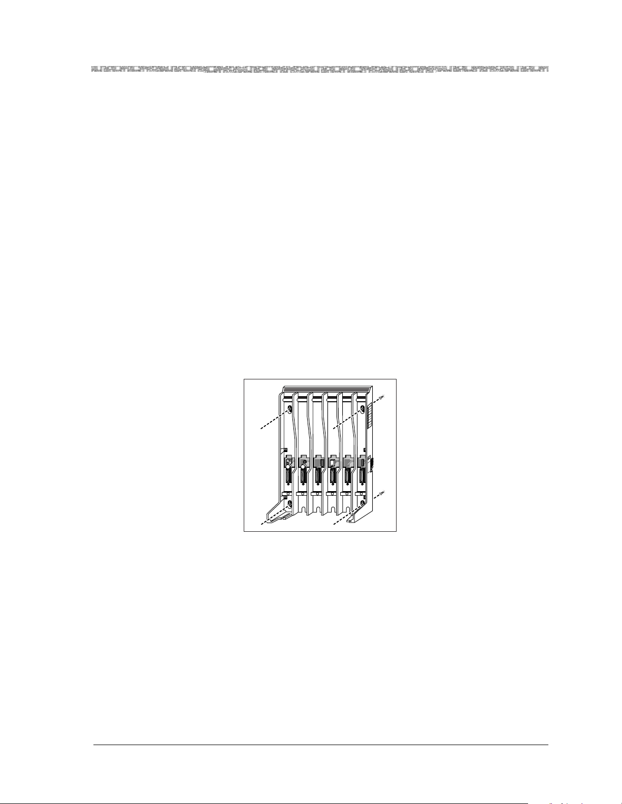
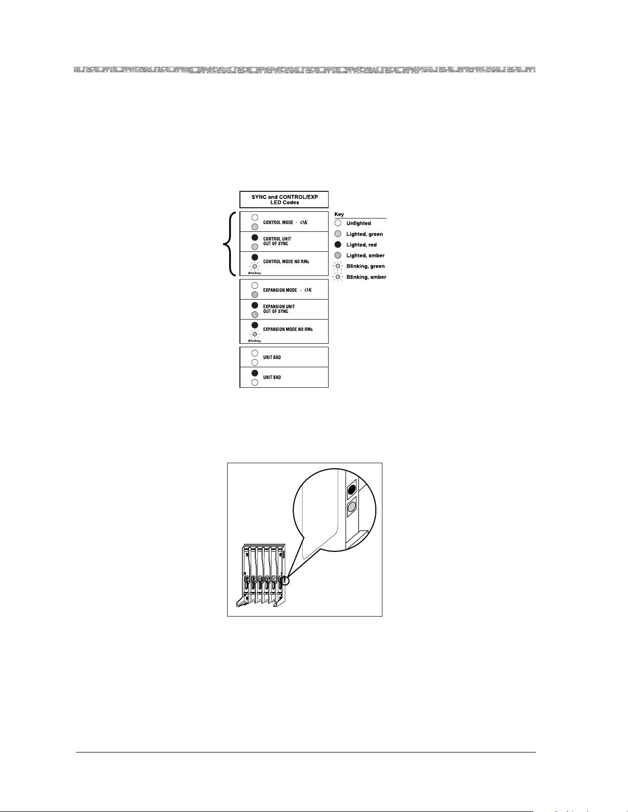
As the following illustration shows, the 117A4 does have an additional LED located on the right side of the
carrier, the CONTROL/EXP ANSION LED, used for determining whether the cabling was installed correctly.
T
Radio
Module
Mounting
Rods
Wall Mount
Hole
Label with
Model Number
(not shown)
RANSTALK
MNNOEAPTRHAN
HAPTERGR
REPRACITE-OK
XERTFAMRU
KLARIENLO
LOREMIPSUM
REPRACITE-OK
XERTFAMRU
KLARIENLO
LOREMIPSUM
REPRACITE-OK
REPRACITE-OK
Radio
Module
Mounting
Rods
SYNC and CONTROL/EXP
LED Codes Label
Wall Mount
Hole
Power Cord
Connector
(not shown)
Card Edge
Connectors
Slot
Numbers
Wall Mount
Hole
Cable
Manager Slot
1 2 3 4
CAUTION
USE ONLY
AT&T CABLE
P⁄N 847667896
IN
OUT
OUT OF SYNC
CONTROL/
EXPANSION
5
6
OUT Jack
CONTROL/EXPANSION LED
(Model 117A4 Only)
Slot
Numbers
Wall Mount
Hole
Rear
Exit Slots
IN Jack
Model 117A4 Car rier Installa tion Instructions
503-801-180
Issue 2 February 1999 5
Page 12

Model 117A4 Carrier Installation Instructions Understanding Carri ers
The followi ng chart explains the label that identifies the jac ks and LEDs on the 117A4 carrier.
Label Explanation
IN Designates the modular jack that accepts the
modular plug and cable from the preceding
carrier to th e left. If the jack is in use, this
carrier is an “Ex p a nsion” ca r ri e r.
OUT Des ignates the modul ar jack that accept s a
modular plug and cable to connect this
carrier to the next carrier to the ri ght. Thi s
carrie r can be ei th er a “ Cont ro l” ca r rie r (if it
is the leftmost carrier ) or an “Ex p an sion”
carrier.
OUT OF SYNC Designates the upper of two LEDs. If the
LED is not lit, ca rrier is “in sync.”
If the LED glows red, the carrier is out of
synchronization. Call Customer Support as
described on the insi de front cover of this
book.
CONTROL/EXPANSION Designates the lower of two LEDs. The
color of the LED indicates the carrier
configuration:
Control carrier = green LED
Expansion carrier = amber LED
The light pattern indicates whether the
carrier is operational:
Glowing steadily = no problem.
Blinking = no radio module(s) in the
carrier.
Model 117A4 Car rier Installa tion Instructions
503-801-1806 Issue 2 February 1999
Page 13

Understanding Carriers Model 117A4 Carrier Installation Ins tructions
The label at the top of t he right side of the carrier is provided to help you int erpret the LED li ghts. The fi rst three
lines on this label refer to LEDs on the control carrier; the next three lines refer to the LEDs on each of the
expansion carriers; and the last two lines apply to all carriers.
Model 117A4 Car rier Installa tion Instructions
503-801-180
Issue 2 February 1999 7
Page 14

Model 117A4 Carrier Installation Instructions Understanding Carri ers
Positioning Your Carrier(s)
Each carrier holds up to six radio modules. Eac h radio module and its corresponding handset opera tes within a
single zone of coverage.
Approximately
Approximately
500 to 900 feet in a
500 to 900 feet in a
typical office building;
typical office building;
up to 1200 feet in
up to 1200 feet in
an unobstructed
an unobstructed
environment
environment
POWER
Single Radio Module,
RADIO
Single Radio Module,
PASS
Single Carrier, or
Single Carrier, or
Multiple Carriers
Multiple Carriers
The range of your handset(s) depends on your particular operating environment. For indoor use, walls between
the handset and th e radio module will reduce th e phone’s range. Av oid co ncentr ati ons of struc tural met al, s uch as
steel and aluminum , and reinforced concrete.
The MDW telephones have a b uilt-in testing feature that you can use before final insta llation to help determine
proper placement of the ra dio module. To perform the test s, all you need is an electri cal outlet for the radio
module and a charged battery pack in the handset (you do not nee d a communications system switch/control
unit).
Performance/Range
Test in Wireless Test
Mode
Using the signal-strength test and the voice-quality test together, you can de termine:
•
if the installation has been done correctly.
•
if the handsets and bases are working properly.
•
the range in which your MDW 9031/9031DCP Pocket Phone performs best at
your site.
Close Up Test
At no more than 5–10 feet (1.5–3.1 m) from its radio module, use the following
procedure:
1
Make sure the handset is turned off.
2
Press and h old the Select b utton (" ) for three seconds.
Model 117A4 Car rier Installa tion Instructions
503-801-1808 Issue 2 February 1999
Page 15

Understanding Carriers Model 117A4 Carrier Installation Ins tructions
3
While s t il l holdin g " , press O.
The handset beeps twice, and the display shows the handset settings, indicating
you are in Local Mode. (While in Local Mode, the MDW telephone can still
recei ve notification of incoming cal ls.)
4
Press “W” (9) to enter Wireless Test Mode..
Note:
In a multiple TransTalk installation, put all of the handests in
Wireless T est Mode at the same time. This allows you to observe
if all handsets are working properly together.
WIRELESS TEST appears on the top line of the handset display. The handset
beeps twice and vibrates, then you hear a simulated dial tone. This dial tone
continues until you exit Wireless Test Mode. While in this mode, the MDW
telephone cannot make or receive calls.
For all set s, do the following.
5
Press 1.
The display should show a 9 or 10 for signal strength (an occasional 8 is
acceptable).
6
Press 2.
The display should show a 9 or 10 for voice quality (an occasional 8 is
acceptable).
Note:
If you are seeing numbers lower than 8-10 for either signal strength or
voice qualit y while performing the Close Up Test, please refer to either
the "Installing a Single Carrier" section, or "Installing Multiple Carriers"
section in this manual. This will ensure that your installation meets all
installation and en vironmental requirements.
Edge of Range Test
1
Periodically check the signal stre ngth and voice quality as you walk away from
the radio module. Each time you press 1 or 2, you get a new reading.
When you see a signal strength of 3 at a power level of 8, you are at the “edge of
range” for the MD W telephone. The distance will vary depend ing on the
environment, building structure, an d other factors. The range in an average office
build ing is 500–7 00 feet (152. 5–21 3.5 m). If, ho we ve r, dense walls interv ene, the
distance could be less.
2
Wit h a si gnal strength of 3, press 2 to check th e voice quali ty. When the vo ic e
quality is 7 or 8, the v oice connection s hould be satisfa ctory. This is the edge of
your usable range.
The followi ng diagram illustrates this P er f ormance/Range test.
Model 117A4 Car rier Installa tion Instructions
503-801-180
Issue 2 February 1999 9
Page 16

Model 117A4 Carrier Installation Instructions Understanding Carri ers
General Positioning
Rules
Close-Up Test
5 to 10 feet (1.5 to 3.1 m)
Signal Strength = 9 to 10
Voice Quality = 9 to 10
*Edge-of-Usable-Range Test
Signal Strength = 3
Voice Quality = 7 to 8
*At High Power—Power Level = 8
POWER
RADIO
PASS
Radio
Module
Failure to observe the following rules regarding locati on an d use will result in poor
performance of your MDW telephone.
•
Position the carrier(s) in a central location, relative to the handset(s) usage area,
leaving at least 6 feet (1.8 m) betw een the ca rrier(s) and the co mmunications
system switch/ control unit or other wired phones. If your switch/control unit is
located in a rem ote lo catio n, yo u may ha ve to run a t elepho ne line cord from your
switch/control uni t to t he cen trall y posit ioned ra dio modul e or carrie r(s). The lin e
cord maximum length is 1,000 feet (305 m) of 26-gauge cable.
•
The carrier(s) should be placed high on the wall for optimum voic e qua lity and
range. Allo w 6–12 i nch es (15.2–30.5 cm) of space be tween the top of t he ant enna
on the radio modules and the ceiling.
•
The carrier(s) should never be inst all ed above a drop, suspende d ceiling.
•
The carrier(s) should not be within 3 feet (.9 m) of any lar ge metal object, and
should not have metal objects in the line of sig ht to the operating ar ea of the
handset.
•
The carrier(s) should not be within 6 feet (1.8 m) of equipment with
micropr ocessors such as answerin g mac h ines, personal computers, and fax
machines; control units, communications system switches, or other phones
(especially speakerphones); competing radio devices such as wireless barcode scanners; electromagnetic equipment such as electric motors; or
electrical main power feeds, junction boxes, circuit-breaker panels, fuse
boxes, or 220-volt power lines.
•
The carrier(s) should not share the same power line as equipment with
microprocessors s uch a s answe ring machines, personal computers, and fax
machi ne s; or ele ct r o mag n etic equ ip ment such as el ec tr i c m o t ors .
•
If your communications system uses an uninterrupti ble power supply, such as a
backup generator, you may want to connect the radio modu le or carrier(s) to that
power suppl y.
Model 117A4 Car rier Installa tion Instructions
503-801-18010 Issue 2 February 1999
Page 17

Install ing a Single Carrier Model 117A4 Carrier Installation Ins tructions
•
Install carrier(s) within 15 feet (5 m) of either side of, and within 6 to 8 feet (1.8
to 2.4 m) above, a properly grounded 3-prong electrical outlet tha t is not
controll ed by an on/off s w itch.
•
Choose a location where handset users will not approach the carrier(s)
within a radius of 6 feet (1.8 m) for 1 or 2 carriers or 10 feet (3 m) for 3
carriers.
•
When installing multiple carriers:
~
Install multiple carriers 1 foot (0.3 m) optimally to 4 feet (1.2 m) apart.
~
Install multiple carriers on the same horizontal axis (do not in st all one carrier
higher or lower than another).
~
Install the control carrier as the leftmost carrier, using only the expansion
cables provided.
!
CAUTION:
Carrier(s) cannot be installed outdoors
Go to one of the following:
•
If installing a single carrier, go to “Installing a Sin g le Carrier.”
•
If installing multiple carriers, go to “Installing Multiple Carrier s.”
Installing a Single Carrier
Be sure you have read “Understanding Carriers.” Then go to one of th e following:
•
“Install ing a Single Carrier on a Shelf or Desk” or
•
“Installing a Single Carrier on a Wall”
Installing a Single Carrier on a Shelf or Desk
•
You will not receive optimum performance if unit is placed on a desk or low
shelf
•
Install as high as poss ible, leaving 6–12 inches (15.2–30.5 cm) between
antennas and ceiling if on high shelf
•
Never ins tall or remove a radio module from a carrier that is plugged into a
wall outlet (hot insertion)
1
Be sure you have determined the optimal placement for your ca rrier using the
Performance/Range test and the positioning guidelines described in “Positioning
Your Ca r rier (s). ”
Model 117A4 Car rier Installa tion Instructions
503-801-180
Issue 2 February 1999 11
Page 18

Model 117A4 Carrier Installation Instructions Install ing a Single Carrier
2
Check to make sure the carrier’s powe r cord is unplugged from the wall outlet
before continuing.
3
Remove the plastic cap covering each radio module’s card edge before installing
the radio modules in the carrier.
4
Starting from the left most slot (#1), insert each ra dio mo dule into the carrier by
hooking it onto the radio module mounting rod. Slowly swing the radio module's
card edg e in t o th e car d ed g e co n ne ct o r on th e ba ck of th e car r ie r.
Model 117A4 Car rier Installa tion Instructions
503-801-18012 Issue 2 February 1999
Page 19

Install ing a Single Carrier Model 117A4 Carrier Installation Ins tructions
5
When the card edge is ful ly sea ted, a snap lock on the botto m of t he radio modul e
will engage.
6
Insert a telephone line cord into the bottom of each radio module.
Model 117A4 Car rier Installa tion Instructions
503-801-180
Issue 2 February 1999 13
Page 20
Model 117A4 Carrier Installation Instructions Install ing a Single Carrier
MUSIC
ON
HOLD
N
S
I
O
N
S
X
T
E
N
S
I
O
N
S
7
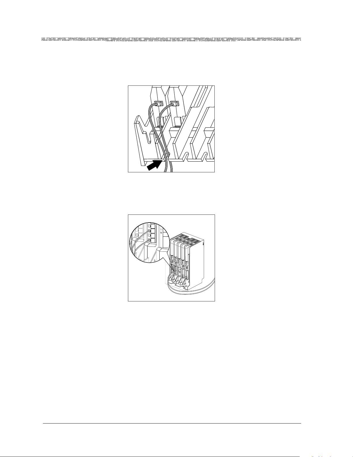
Slide the telephone line cords through the rear exit slots on the bottom of the
carrier. Cords originating from Modules 1 and 6 can share exit slots with cords
from Modules 2 and 5 respectively.
8
Insert the free end of the telephone line cord in to the appropriate extension jac k
or termina l/st ation connec tor on your c ommuni cati ons sys tem switch/c ont rol unit
(refer to your communications system manual for the proper location).
PFT
L
I
N
PFT
E
L
S
I
N
PFT
E
L
PAGE
S
I
N
PFT
E
L
SMDR
S
I
N
PFT
E
L
S
I
N
206
MODULE
E
S
PFT
206
MODULE
PFT
PROCESSOR
E
MODULE
X
T
400
E
E
MODULE
X
N
T
S
400
VOL
E
MODULE
I
N
O
S
N
E
I
S
X
MUSIC
O
ON
T
N
HOLD
E
E
S
X
N
T
S
E
I
N
O
S
N
I
S
O
N
S
Model 117A4 Car rier Installa tion Instructions
503-801-18014 Issue 2 February 1999
Page 21
Install ing a Single Carrier Model 117A4 Carrier Installation Ins tructions
9
Insert the carrier’s AC adapter cord into the left side of the carrier.
1 2345
10
Place the carri er on its fee t to wa rds the bac k of th e shelf or de sk, making s ure it i s
in a stable position. Be sure the telephone line cords come out the rear exit slots
in the back of the unit. Arrange the power cord and telephone line cords beneath
the shelf or desk so no one can step on them or trip o ver them.
Model 117A4 Car rier Installa tion Instructions
503-801-180
Issue 2 February 1999 15
Page 22

Model 117A4 Carrier Installation Instructions Install ing a Single Carrier
11
Insert the carrier’s power cord into the A C adapter, then plug the po wer c ord into
a properly grounded 3-prong wall outlet that is not controlled by an on/off switch.
If appropriate, you can wall-mount the AC adapter using its attached wallmounting bracket.
!
CAUTION:
Never co nnec t or dis connect telephone line cords, or insert or remove radio modules,
while the ca r r ier is plugged into the wall outlet.
12
Now go to "Single Carrier Installation Self Test" (page 22).
Model 117A4 Car rier Installa tion Instructions
503-801-18016 Issue 2 February 1999
Page 23
Install ing a Single Carrier Model 117A4 Carrier Installation Ins tructions
Installing a Single Carrier on a Wall
•
Install high on wall , leaving 6–12 inches (15.2–30.5 cm) bet ween an tennas
and ceil ing
•
Never ins tall or remove a radio module from a carrier that is plugged into a
wall outlet (hot insertion)
1
Be sure you have determined the optimal placement for your ca rrier using the
Performance/Range test and the positioning guidelines described in “Positioning
Your Ca r rier (s). ”
2
Check to make sure the car rier’s power cord is unplugged from the wall outlet
before continu ing.
3
Place th e carrier agains t the wall. Choose a locatio n b acked by a wooden stud (if
unavailable, use toggle bolts inst ead of the supplied wood screws). Hold the
carrier strai ght; use a le v el if nee ded. Using a nail or penc il, m ark scre w loc atio ns
through the four wall-mount holes.
Start the screws, leaving the sc rew heads protruding approximately ½" (12 mm)
from the wall. Place the carrier assembly over the screws, then slide it downward
to lock it into place. Tighten the screws.
1 2 3 4
T
RANSTALK
N
A
H
R
T
P
A
E
O
R
N
G
N
R
E
M
T
P
A
H
K
O
E
IT
C
A
R
P
E
R
U
R
M
A
F
T
R
O
E
L
X
N
IE
R
A
L
K
M
U
S
IP
M
E
R
O
L
K
-O
E
IT
C
A
R
P
E
R
U
R
M
A
F
T
R
O
E
L
X
N
IE
R
A
L
K
M
U
S
IP
M
E
R
O
L
K
-O
E
IT
C
A
R
P
E
R
K
-O
E
IT
C
A
R
P
E
R
CAUTION
LY
N
E O
E
US
BL
A
T C
&
7896
AT
66
47
8
⁄N
P
IN
OUT
OUT OF SYNC
CONTROL/
EXPANSION
5
6
Model 117A4 Car rier Installa tion Instructions
503-801-180
Issue 2 February 1999 17
Page 24

Model 117A4 Carrier Installation Instructions Install ing a Single Carrier
4
Remove the plastic cap covering each radio module’s card edge before inserting
the radio modules into the carrier.
5
Starting from the left most slot (#1), insert each ra dio mo dule into the carrier by
hooking it onto the radio module mounting rod. Slowly swing the radio module's
card edg e in t o th e car d ed g e co n ne ct o r on th e ba ck of th e car r ie r.
Model 117A4 Car rier Installa tion Instructions
503-801-18018 Issue 2 February 1999
Page 25
Install ing a Single Carrier Model 117A4 Carrier Installation Ins tructions
6
When the card edge is ful ly sea ted, a snap lock on the botto m of t he radio modul e
will engage.
7
Insert a telephone line cord into the bottom of each radio module.
Model 117A4 Car rier Installa tion Instructions
503-801-180
Issue 2 February 1999 19
Page 26

Model 117A4 Carrier Installation Instructions Install ing a Single Carrier
MUSIC
ON
HOLD
N
S
I
O
N
S
X
T
E
N
S
I
O
N
S
8
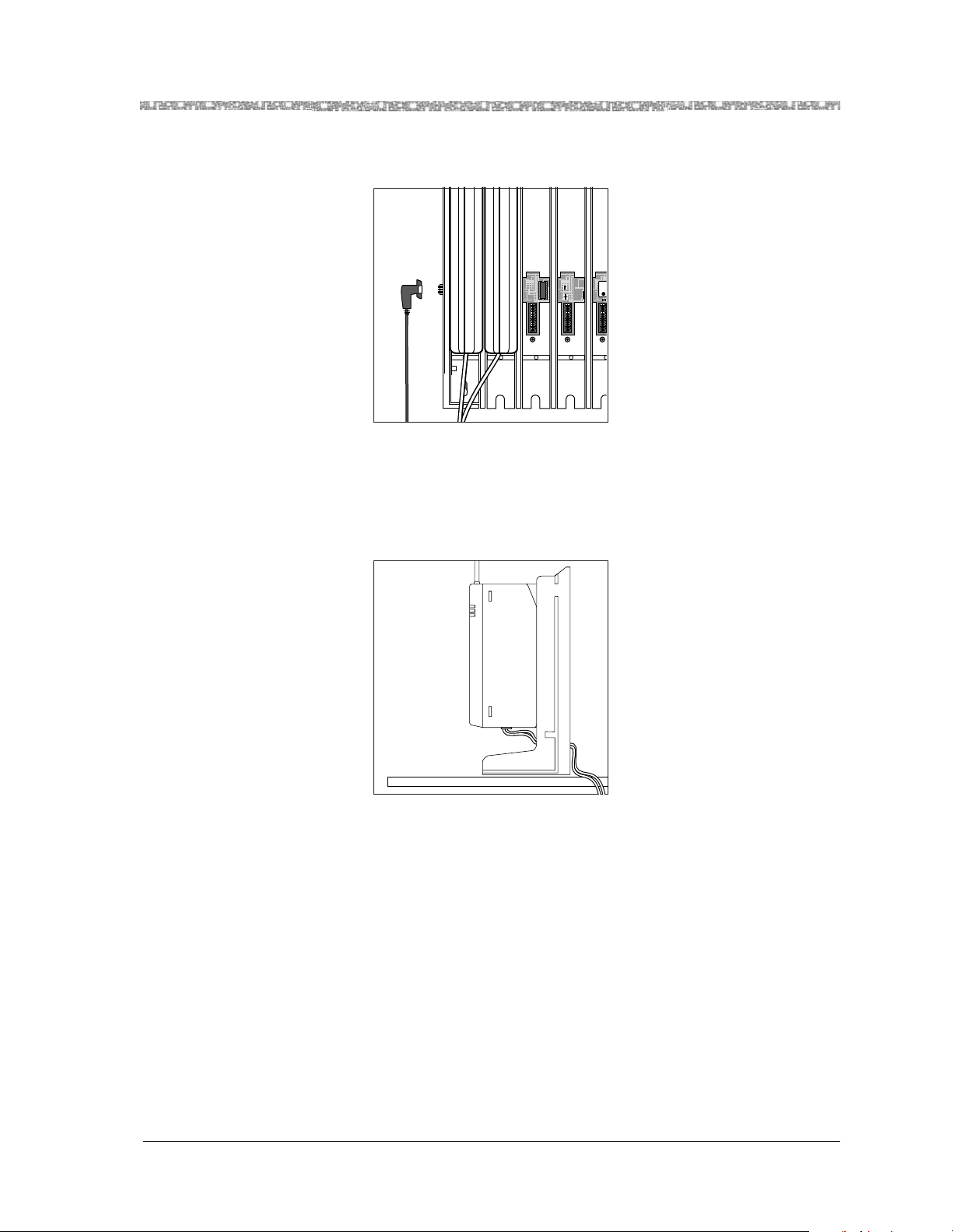
Slide the tele phone line cords through t he ca ble manager slot on the left front of
the car rier.
9
Insert the free end of each telephone li ne cord into t he appropriate extension jack
or termina l/st ation connec tor on your c ommuni cati ons sys tem switch/c ont rol unit
(refer to your communications system manual for the proper location).
PFT
L
I
N
PFT
E
L
S
I
N
PFT
E
L
PAGE
S
I
N
PFT
E
L
SMDR
S
I
N
PFT
E
L
S
I
N
206
MODULE
E
S
PFT
206
MODULE
PFT
PROCESSOR
E
MODULE
X
T
400
E
E
MODULE
X
N
T
S
400
VOL
E
MODULE
I
N
O
S
N
E
I
S
X
MUSIC
O
ON
T
N
HOLD
E
E
S
X
N
T
S
E
I
N
O
S
N
I
S
O
N
S
Model 117A4 Car rier Installa tion Instructions
503-801-18020 Issue 2 February 1999
Page 27

Install ing a Single Carrier Model 117A4 Carrier Installation Ins tructions
10
Plug the carrier’s AC adapter cord into the left side of the carrier.
1 2345
11
Insert the carrie r’s power cord into the A C a dapter, then plug the po wer c ord into
a properly grounded 3-prong wall outlet that is not controlled by an on/off swit ch.
If appropriate , you can wall-mount the AC adapter using its attached wallmounting bracket.
!
CAUTION:
Never co nnec t or disconnect telephone line cords, or insert or remove radio modules,
while the ca r r ier is plugged into the wa ll outlet.
12
Now go to "Single Carri er Installation Self Test" (page 22).
Model 117A4 Car rier Installa tion Instructions
503-801-180
Issue 2 February 1999 21
Page 28
Model 117A4 Carrier Installation Instructions Install ing a Single Carrier
Single Carrier Installation Self Test
1
A single carrier must al ways function as a control carrier. Wait a few seconds,
then check the LED(s) on the right side of the Model 117A4 carrie r.
Compare the OUT OF SYNC and CONTROL/EXPANSION LEDs against the
top three lines on the “SYNC and CONTROL/EXP LED Codes ” label.
2
If the OUT OF SYNC LED is lit, power down, wait at leas t 15 se cond s, and then
repower the carrier. If the LED is still lit, call for Customer Support as described
on the inside cover of this book.
OUT OF S YNC
CONTROL/
T
4
1 2 3 4
3
Verify that the carrier’s CONTROL/EXPANSION LED is lit and that it s col or is
green. This is correct for a single-carrier installation.
RANSTALK
21
O N
21
O N
5
EXPANSION
N
A
H
R
T
P
A
E
O
N
N
R
M
G
R
E
T
P
A
H
K
O
-
E
T
I
C
A
R
P
E
R
U
R
M
A
F
T
R
E
X
O
L
N
E
I
R
A
L
K
M
U
S
P
I
M
E
R
O
L
K
O
-
E
T
I
C
A
R
P
E
R
U
R
M
A
F
T
R
E
X
O
L
N
E
I
R
A
L
K
M
U
S
P
I
M
E
R
O
L
K
O
-
E
T
I
C
A
R
P
E
R
K
O
-
E
T
I
C
A
R
P
E
R
N
TIO
U
A
C
Y
L
N
O
E
E
S
L
U
B
A
C
T
896
&
T
67
A
6
47
8
⁄N
P
IN
UT
O
C
SYN
OF
UT
O
6
Model 117A4 Car rier Installa tion Instructions
503-801-18022 Issue 2 February 1999
Page 29

Install ing Multiple Carriers Model 117A4 Carrier Installati on Instructions
4
Verify the POWER and PASS LEDs on each radio module are lit. If a radio
module’s PASS LED does not light, po wer do wn the carrie r and the module , wait
15 seconds, and repower the module and then the carrier.
POWER
RADIO
PASS
Radio
Module
POWER
RADIO
PASS
Note:
The RADIO LED also may light upon installati on; however, since the
RADIO LED has no significance during installation, ignore its operation.
The RADIO LED indicates a connection between the handset an d the
radio module; it lights when the handset is being used as long as the
battery pack in the handset is charged.
Installing Multiple Carriers
•
Install each carrier high on wall, le avi ng 6–12 i nches (15. 2–30 .5 cm) bet ween
antennas and ceiling
•
Install each carrier 1 foot (0.3 m) optimal to 4 feet (1.2 m) from its
neighboring carrier
•
Never ins tall or remove a radio module from a carrier that is plugged into a
wall outlet (hot insertion)
Multiple carrier installation involves several stages:
•
Mounting the carri ers on the wall and cabling them
•
Installing a single radio module in each ca r rier
•
Installing the remaining radio modules
The most efficient method for installing carriers and their radio modules is to perform self tests after each stag e
of the installation. This enables you to spot any problems at an early stage, and avoid the necessity for
deinstalling the components in orde r to so lve problems.
Model 117A4 Car rier Installa tion Instructions
503-801-180
Issue 2 February 1999 23
Page 30

Model 117A4 Carrier Installation Instructions Installing Multiple Carriers
Mounting and Cabling Multiple Carriers
Be sure you have determined the optimal placement for you r carrier using the Performance/Range test and the
positioning guidelines described in “Positioning Your Carrier(s).”
If you are installing with 117A3 carriers, see your MDW telephone Installation and Use manual for the proper
Power and Control/Expansion DIP swi tch settings.
1
Check to make sure the carrier’s powe r cord is unplugged from the wall outlet
before continuing.
2
Choose a location backed by a wooden stud for the carrier (if unavailable, use
toggle bolts ins tead of the supplied wo od screws).
Note:
The leftmost carrier must be the control carrier; all of the others are
expansion carriers.
T
RANSTALK
AN
PTRH
R
MNNOEA
HAPTERG
K
ACITE-O
REPR
U
R
LO
XERTFAM
KLARIEN
IPSUM
REM
LO
ITE-OK
REPRAC
RU
XERTFAM
RIENLO
KLA
IPSUM
EM
R
LO
ACITE-OK
REPR
K
REPRACITE-O
CAUTION
Y
L
N
O
SE
LE
U
B
A
T C
96
8
T&
67
A
476
8
P⁄N
IN
T
U
O
C
YN
F S
/
OL
OUT O
R
N
ONT
C
NSIO
A
P
EX
1 2 3 4
3
Place the carrier against t he wall, leaving enough room to the right for additional
5
6
carrier(s) if applicable. Hold the carrier straight; use a level if needed. Using a
nail or pencil, mark screw locations through the four wall-mount holes. Start the
screws, leaving the screw heads protruding approximately ½" (12 mm) from the
wall. Repeat Steps 1 through 3 for each carrie r, leaving 1 foot (0.3 m) optimally
to 4 feet (1.2 m) between carriers.
4
Place the carrier over the screws, th en slide it downward to lock it into place. Be
sure that the leftmost carrier is the control carrier. Tighten the screws . Repea t for
each carrier.
Model 117A4 Car rier Installa tion Instructions
503-801-18024 Issue 2 February 1999
Page 31

Install ing Multiple Carriers Model 117A4 Carrier Installati on Instructions
To
Expansion
Carrier #1
CAUTION
USE ONLY
AT&T CABLE
P N 847667896
IN
OUT
OUT OF SYNC
CONTROL/
EXPANSION
From
Control Carrier
To
Expansion
Carrier #2
CAUTION
USE ONLY
AT&T CABLE
P N 847667896
IN
OUT
OUT OF SYNC
CONTROL/
EXPANSION
To
Expansion
Carrier #3
CAUTION
USE ONLY
AT&T CABLE
P N 847667896
IN
OUT
OUT OF SYNC
CONTROL/
EXPANSION
To
Expansion
Carrier #4
CAUTION
USE ONLY
AT&T CABLE
P N 847667896
IN
OUT
OUT OF SYNC
CONTROL/
EXPANSION
CAUTION
USE ONLY
AT&T CABLE
P N 847667896
IN
OUT
OUT OF SYNC
CONTROL/
EXPANSION
Using the expansion cable provided with each carrier, you can link up to five
carriers.
21
O N
1 2 3 4
Control
Carrier
T
RANSTALK
MNNOEAPTRHAN
HAPTERGR
REPRACITE-OK
XERTFAMRU
KLARIENLO
LOREMIPSUM
REPRACITE-OK
XERTFAMRU
KLARIENLO
LOREMIPSUM
REPRACITE-OK
REPRACITE-OK
CAUTION
Y
L
N
O
E
E
S
L
U
B
A
21
C
6
T
9
8
&
7
T
6
A
O N
6
7
4
8
N
P
IN
T
U
O
C
N
Y
S
F
O
/
T
L
U
O
O
R
T
N
N
O
C
IO
S
N
A
P
X
E
5 1 2 3 4
6
Expansion
Carrier #1
5
21
O N
21
O N
5 1 2 3 4
From
Expansion
Carrier #1
T
RANSTALK
MNNOEAPTRHAN
HAPTERGR
REPRACITE-OK
XERTFAMRU
KLARIENLO
LOREMIPSUM
REPRACITE-OK
XERTFAMRU
KLARIENLO
LOREMIPSUM
REPRACITE-OK
REPRACITE-OK
CAUTION
Y
L
N
O
E
E
S
L
U
B
A
C
6
T
9
8
&
7
T
6
A
6
7
4
8
N
P
IN
T
U
O
C
N
Y
S
F
O
/
T
L
U
O
O
R
T
N
N
O
C
IO
S
N
A
P
X
E
6
21
O N
Expansion
Carrier #2
T
RANSTALK
MNNOEAPTRHAN
HAPTERGR
REPRACITE-OK
XERTFAMRU
KLARIENLO
LOREMIPSUM
REPRACITE-OK
XERTFAMRU
KLARIENLO
LOREMIPSUM
REPRACITE-OK
REPRACITE-OK
CAUTION
Y
L
N
O
E
E
S
L
U
B
A
21
C
6
T
9
8
&
7
T
6
A
O N
6
7
4
8
N
P
IN
T
U
O
C
N
Y
S
F
O
/
T
L
U
O
O
R
T
N
N
O
C
IO
S
N
A
P
X
E
5
6
O N
1 2 3 4
Expansion
Carrier #3
21
From
Expansion
Carrier #2
T
RANSTALK
MNNOEAPTRHAN
HAPTERGR
REPRACITE-OK
XERTFAMRU
KLARIENLO
LOREMIPSUM
REPRACITE-OK
XERTFAMRU
KLARIENLO
LOREMIPSUM
REPRACITE-OK
REPRACITE-OK
CAUTION
Y
L
N
O
E
E
S
L
U
B
A
21
C
6
T
9
8
&
7
T
6
A
O N
6
7
4
8
N
P
IN
T
U
O
C
N
Y
S
F
O
/
T
L
U
O
O
R
T
N
N
O
C
IO
S
N
A
P
X
E
5
6
(Fourth and fifth carriers can be
used only with PBX extensions.)
21
O N
1 2 3 4
Expansion
Carrier #4
Connect an expansion cable to the OUT jack of the control carrier.
Expansion
Carrier #3
T
21
O N
5
From
RANSTALK
MNNOEAPTRHAN
HAPTERGR
REPRACITE-OK
XERTFAMRU
KLARIENLO
LOREMIPSUM
REPRACITE-OK
XERTFAMRU
KLARIENLO
LOREMIPSUM
REPRACITE-OK
REPRACITE-OK
CAUTION
Y
L
N
O
E
E
S
L
U
B
A
C
6
T
9
8
&
7
T
6
A
6
7
4
8
N
P
IN
T
U
O
C
N
Y
S
F
O
/
T
L
U
O
O
R
T
N
N
O
C
IO
S
N
A
P
X
E
6
Model 117A4 Car rier Installa tion Instructions
CAUTION
USE ONLY
AT&T CABLE
P⁄N 847667896
IN
OUT
OUT OF SYNC
CONTROL/
EXPANSION
503-801-180
Issue 2 February 1999 25
Page 32

Model 117A4 Carrier Installation Instructions Installing Multiple Carriers
6
Insert the free end of the expa nsion cable into t he IN jack of the e xpansi on carri er
immediately to the right of the control carrier.
Note:
Although insta lling an expansion cable into the wrong IN or OUT jack
will not harm either c arrier, doing so causes all handsets to work
improperly and the OUT OF SYNC LED to light.
CAUTION
USE ONL Y
AT&T CABLE
P⁄N 847667896
IN
OUT
OUT OF SYNC
CONTROL/
EXPANSION
7
If you have a sec ond expansion carrier:
a
Connect an expansion cable to the OUT jack of expansion carrier #1.
b
Insert the free end o f the expansion cable into the IN jack of e xpansion carrier
From
Control
Carrier
#2.
If you have a third expansi on ca rrier, see the cabling illustration on page 34 for a
four-carrier setup.
8
Plug an AC adapter cord into the left side of each carrier.
1 2345
Model 117A4 Car rier Installa tion Instructions
503-801-18026 Issue 2 February 1999
Page 33

Install ing Multiple Carriers Model 117A4 Carrier Installati on Instructions
9
Insert each carrier’s power cord into its AC adapter.
If appropriate, you can wall-mount each AC adapter using its attached wall-
mounting bracket.
10
Plug each carrier’s power cord into one of the following po wer sources that is not
controlled by an on/off switch.
~
Surge-suppressor strip.
~
Properly grounded 3-prong wall outlets. (See “Wall outlets” in the follo w ing
chart for the order in which to power up the carriers .)
Model 117A4 Car rier Installa tion Instructions
503-801-180
Issue 2 February 1999 27
Page 34
Model 117A4 Carrier Installation Instructions Installing Multiple Carriers
Power the carriers as follows:
If the carriers a re
plugged into... Then...
One surge suppressor strip Power the strip
Result: All carriers will turn on simultaneously.
Wall outle ts Plug in the power f or the Carrier s in this order:
T
RANSTALK
N
A
H
TR
P
EA
O
N
N
R
M
TERG
P
A
H
K
ITE-O
AC
R
P
RE
U
R
M
TFA
R
E
X
LO
N
IE
R
LA
K
UM
S
IP
EM
R
LO
K
ITE-O
C
A
R
REP
U
R
M
TFA
R
XE
LO
IEN
R
LA
K
M
SU
IP
M
E
R
LO
K
-O
ITE
C
A
PR
RE
K
ITE-O
AC
PR
RE
T
RANSTALK
N
A
H
TR
P
EA
O
N
N
R
M
G
TER
P
HA
CITE-OK
A
EPR
R
U
R
M
A
TF
R
E
X
LO
N
IE
R
LA
K
M
U
S
IP
EM
R
LO
K
ITE-O
AC
R
P
RE
U
R
M
TFA
XER
LO
IEN
R
LA
K
SUM
IP
M
E
R
LO
K
-O
ITE
C
A
PR
E
R
K
ITE-O
AC
PR
RE
T
RANSTALK
AN
H
PTR
A
E
O
N
N
R
M
G
TER
P
A
H
K
ITE-O
C
A
R
EP
R
U
R
M
A
TF
R
XE
LO
N
IE
R
LA
K
M
U
S
IP
EM
R
LO
-OK
ITE
C
A
R
EP
R
U
R
M
TFA
R
XE
LO
IEN
LAR
K
M
SU
IP
M
E
R
LO
K
-O
ITE
AC
PR
E
R
K
-O
ITE
C
A
PR
E
R
T
RANSTALK
N
A
H
TR
P
EA
O
N
N
R
M
TERG
P
A
H
K
-O
CITE
A
EPR
R
U
R
M
TFA
ER
X
LO
IEN
R
LA
K
UM
S
IP
EM
R
LO
K
CITE-O
A
R
EP
R
U
R
M
TFA
R
XE
LO
N
IE
LAR
K
M
SU
IP
EM
R
LO
K
-O
ITE
C
A
PR
E
R
K
-O
ITE
C
A
PR
E
R
T
RANSTALK
N
HA
TR
AP
E
O
NN
R
M
G
R
PTE
A
H
K
-O
ITE
C
A
PR
E
R
U
R
M
TFA
ER
X
LO
IEN
R
A
KL
M
SU
IP
M
RE
O
L
K
E-O
CIT
RA
EP
R
U
R
M
FA
T
R
E
X
LO
IEN
R
LA
K
M
U
IPS
EM
R
LO
K
E-O
IT
C
RA
P
E
R
K
ITE-O
AC
PR
E
R
!
CAUTION:
21
O N
1 2 3 4
Control
Carrier
1
N
UTIO
CA
Y
L
N
O
E
E
S
L
U
21
B
A
C
T
96
&
8
O N
T
A
667
7
84
⁄N
P
IN
T
U
O
C
N
Y
S
F
O
T
U
O
5
1 2 3 4
6
Expansion
Carrier #1
N
UTIO
21
CA
O N
Y
L
N
O
E
E
S
L
U
21
B
A
C
T
&
O N
T
7896
A
766
84
⁄N
P
IN
T
U
O
C
N
Y
S
F
O
T
U
O
5
6
2 3
Never connect or disconnect expansion cables or tele phone line cords, or inse rt or
remove radio modules, while the carrier is plugged into the wall outlet.
11
Now go to "Multiple Carrier Mounting and Cab ling Self Test" (page 28).
Multiple Carrier Mounting and Cabling Self Test
1
Wait a few seconds after powering up the carriers, then verify that the red OUT
OF SYNC LEDs on all carriers are lit. This is normal when no radio modules
have yet been installed. The CONTROL/EXPANSI ON LEDs (Model 117A4
only) should also be lit and blinking:
~
Model 117A4 control carrier = Green blinking
~
Model 117A4 expansion carrier(s) = Green blinking
A Model 117A3 carrier has no CONTROL/EXP ANSI ON LED, bu t th e DIP
switch in Slot 4 of the carri er must be set cor r ectly to either Control or
Expansion.
The following il lus tration shows the correct LED status for a four-carrier
installation with no radio modules installed yet. This example installation has
three 117A4 carriers—one acting as the control carrier and the oth er two acting
as expansion carriers—and one 117A3 carrier acting as an expansion carrier.
21
O N
21
O N
1 2 3 4
Expansion
Carrier #2
5
N
UTIO
CA
Y
L
N
O
E
E
S
L
U
B
A
C
T
96
T&
A
76678
84
⁄N
P
IN
T
U
O
C
N
Y
S
F
O
T
U
O
6
21
O N
21
O N
1 2 3 4
Expansion
Carrier #3
4
5
N
UTIO
CA
Y
L
N
E O
E
S
L
U
B
A
C
T
96
8
T&
A
7667
84
P⁄N
IN
T
U
O
C
N
Y
S
F
O
T
U
O
6
21
O N
21
O N
1 2 3 4
Expansion
Carrier #4
5
N
TIO
U
CA
LY
N
O
E
S
LE
U
B
A
C
6
T
9
&
T
A
678
76
84
⁄N
P
IN
T
U
O
C
N
Y
S
F
O
T
U
O
5
6
Model 117A4 Car rier Installa tion Instructions
503-801-18028 Issue 2 February 1999
Page 35

Install ing Multiple Carriers Model 117A4 Carrier Installati on Instructions
OUT OF SYNC (red)
CONTROL/
EXPANSION
4
O N
1 2 3 4
(green) CONTROL/
21
21
O N
5 1 2 3 4
Control
Carrier
Model
117A4
N
A
H
R
T
P
A
E
O
R
N
G
N
R
E
T
P
A
H
K
O
-
E
IT
C
A
R
P
E
R
U
R
M
A
F
T
R
O
E
L
X
N
E
I
R
A
L
K
M
U
S
P
I
M
E
R
O
L
K
O
-
E
IT
C
A
R
P
E
R
U
R
M
A
F
T
R
O
E
L
X
N
E
I
R
A
L
K
M
U
S
P
I
M
E
R
O
L
K
O
-
E
T
I
C
A
R
P
E
R
K
O
-
E
IT
C
A
R
P
E
R
N
Y
L
LE
B
896
67
IN
OUT
OUT OF SYNC (red)
(DIP switch
in Slot 4 set to
Expansion)
4
21
O N
21
O N
5
Expansion
Carrier #2
Model
117A3
OUT OF SYNC (red)
RANSTALK
6
4
CAUTION
Y
L
N
O
E
E
S
L
U
B
A
C
6
T
9
&
8
T
7
A
6
6
7
4
8
⁄N
P
IN
UT
O
C
YN
F S
T O
U
O
21
O N
1 2 3 4
T
EXPANSION
(green)
T
RANSTALK
21
O N
5
6
Expansion
Carrier #3
Model
117A4
OUT OF SYNC (red)
RANSTALK
6
4
N
A
H
R
T
P
A
E
O
R
N
G
N
R
E
M
T
P
A
H
K
O
-
E
IT
C
A
R
P
E
R
U
R
M
A
F
T
R
O
E
L
X
N
IE
R
A
L
K
M
U
S
IP
M
E
R
O
L
K
O
-
E
T
I
C
A
R
P
E
R
U
R
M
A
F
T
R
O
E
L
X
N
IE
R
A
L
K
M
U
S
P
I
M
E
R
O
L
K
O
-
E
T
I
C
A
R
P
E
R
K
O
-
E
T
I
C
A
R
P
E
R
N
TIO
CAU
Y
L
N
O
SE
LE
U
B
A
T C
896
T&
67
A
6
7
4
8
⁄N
P
IN
OUT
OUT OF SYNC
CONTROL/
EXPANSION
O N
T
EXPANSION
(green) CONTROL/
T
RANSTALK
M
AUTIO
21
C
N
O
E
S
U
A
21
T C
T&
A
O N
6
7
4
8
⁄N
P
OUT OF SYNC
CONTROL/
EXPANSION
5 1 2 3 4
6
Expansion
Carrier #1
Model
117A4
2
At this stage of your installation, the LE Ds di splayed should match the third of
N
A
H
R
T
P
A
E
O
R
N
G
N
R
E
M
T
P
A
H
K
O
-
E
T
I
C
A
R
P
E
R
U
R
M
A
F
T
R
O
E
L
X
N
E
I
R
A
L
K
M
U
S
IP
M
E
R
O
L
K
O
-
E
IT
C
A
R
P
E
R
U
R
M
A
F
T
R
O
E
L
X
N
IE
R
A
L
K
M
U
S
P
I
M
E
R
O
L
K
O
-
E
IT
C
A
R
P
E
R
K
O
-
E
IT
C
A
R
P
E
R
N
AUTIO
C
Y
L
N
O
SE
LE
U
B
A
C
6
T
&
T
789
A
66
47
8
⁄N
P
IN
OUT
OUT OF SYNC
CONTROL/
EXPANSION
OUT OF SYNC (red)
CONTROL/
EXPANSION
4
21
O N
21
O N
1 2 3 4
5
Expansion
Carrier #4
Model
117A4
(green)
T
RANSTALK
N
A
H
R
T
P
A
E
O
R
N
G
N
R
E
M
T
P
A
H
K
O
-
E
T
I
C
A
R
P
E
R
U
R
M
A
F
T
R
O
E
L
X
N
E
I
R
A
L
K
M
U
S
IP
M
E
R
O
L
K
O
-
E
IT
C
A
R
P
E
R
U
R
M
A
F
T
R
O
E
L
X
N
IE
R
A
L
K
M
U
S
P
I
M
E
R
O
L
K
O
-
E
IT
C
A
R
P
E
R
K
O
-
E
IT
C
A
R
P
E
R
N
UTIO
A
C
Y
L
N
O
E
S
LE
U
B
A
6
T C
&
89
T
7
A
766
4
8
⁄N
P
IN
OUT
OUT OF SYNC
CONTROL/
EXPANSION
6
the SYNC and CONTR O L/EXP LED Codes label, depending on whether the
carrier is the control or an expansion carrier.
3
If the LEDs on your installation do not reflect this pattern, there is probably a
mistake i n the ca bling. Po wer do wn the carrie rs and check t hat you have followed
Steps 6 through 8 in “Mounting and Cabling Multiple Carriers” correctly.
4
If your LEDs match the pattern in the illustration, you can feel confident that
your carrier s are cabled corr ectly.
5
Now go on to "Instal ling a Single Radio Modul e in E ac h Carrier" (page 30).
Model 117A4 Car rier Installa tion Instructions
503-801-180
Issue 2 February 1999 29
Page 36

Model 117A4 Carrier Installation Instructions Installing Multiple Carriers
Installing a Single Radio Module in Each Carrier
1
Power down the carriers.
2
Remove the plastic cap covering each radio module’s card edge before inserting
the radio modules into the carriers.
3
Working from left to righ t, insert a radi o module into the f irst sl ot (Slot 1) of each
carrier; hook each radio module onto the mount ing rod. Slowly swing the radio
module’s card edge into the card edge connector on the back of the carrier.
(Exception: use Sl ot 6 instead of Slot 1 for a Model 117A3 con trol carrier.)
Note:
Slot 6 of a Model 117A3 control carrier must always contain a radio
module to pass the synchronization sig nal to the next carrier.
A Model 117A4 carrier does not require Slot 6 to be filled.
Model 117A4 Car rier Installa tion Instructions
503-801-18030 Issue 2 February 1999
Page 37

Install ing Multiple Carriers Model 117A4 Carrier Installati on Instructions
4
When the card edge is ful ly sea ted, a snap lock on the botto m of t he radio modul e
will engage.
5
Insert a telephone line cord into the bottom of each radio module.
Model 117A4 Car rier Installa tion Instructions
503-801-180
Issue 2 February 1999 31
Page 38

Model 117A4 Carrier Installation Instructions Installing Multiple Carriers
MUSIC
ON
HOLD
N
S
I
O
N
S
X
T
E
N
S
I
O
N
S
6
Slide the tele phone line cords through t he ca ble manager slot on the left front of
each carrier.
7
Insert the free end of the telephone line cord in to the appropriate extension jac k
or termina l/st ation connec tor on your c ommuni cati ons sys tem switch/c ont rol unit
(refer to your communications system manual for the proper location).
PFT
L
I
N
PFT
E
L
S
I
N
PFT
E
L
PAGE
S
I
N
PFT
E
L
SMDR
S
I
N
PFT
E
L
S
I
N
206
MODULE
E
S
PFT
206
MODULE
PFT
PROCESSOR
E
MODULE
X
T
400
E
E
MODULE
X
N
T
S
400
VOL
E
MODULE
I
N
O
S
N
E
I
S
X
MUSIC
O
ON
T
N
HOLD
E
E
S
X
N
T
S
E
I
N
O
S
N
I
S
O
N
S
Model 117A4 Car rier Installa tion Instructions
503-801-18032 Issue 2 February 1999
Page 39

Install ing Multiple Carriers Model 117A4 Carrier Installati on Instructions
8
Power the carriers as follows:
If the c a rriers are
plugged into... Then...
One surge suppressor strip Power the strip
Result: All carriers will turn on simultaneously.
Wall outle ts Plug in the power f or the Carrie r s in this order:
T
RANSTALK
N
A
H
PTR
EA
O
N
N
R
M
RG
E
PT
A
H
K
ITE-O
AC
R
P
RE
U
R
M
FA
RT
XE
O
NL
IE
R
LA
K
UM
S
IP
M
E
R
LO
K
-O
CITE
A
R
EP
R
U
MR
TFA
R
XE
LO
IEN
R
LA
K
M
U
IPS
M
E
R
LO
K
ITE-O
C
A
PR
RE
K
ITE-O
AC
R
REP
T
RANSTALK
N
A
H
PTR
EA
O
N
N
R
M
G
ER
PT
HA
ITE-OK
AC
EPR
R
U
R
AM
F
RT
XE
O
NL
IE
R
LA
K
M
U
S
IP
M
E
R
LO
K
-O
ITE
AC
R
P
E
R
U
R
M
TFA
R
XE
LO
IEN
R
LA
K
UM
IPS
EM
R
LO
K
ITE-O
C
A
PR
E
R
K
-O
ITE
AC
R
REP
T
RANSTALK
AN
H
PTR
A
E
O
N
N
R
M
G
ER
PT
A
H
K
CITE-O
A
R
EP
R
U
R
FAM
T
R
XE
O
NL
IE
R
KLA
UM
S
IP
M
E
R
LO
K
ITE-O
AC
R
EP
R
U
R
M
TFA
R
XE
LO
IEN
LAR
K
M
U
IPS
EM
R
LO
K
ITE-O
AC
PR
RE
K
-O
ITE
C
A
R
P
RE
T
RANSTALK
N
A
H
PTR
EA
O
N
N
R
M
G
ER
PT
A
H
K
ITE-O
AC
EPR
R
U
R
M
FA
T
R
XE
LO
N
IE
R
KLA
UM
S
IP
M
E
R
LO
K
-O
CITE
A
R
EP
R
U
R
FAM
RT
XE
LO
N
IE
R
LA
K
UM
IPS
EM
R
LO
K
ITE-O
C
A
PR
E
R
K
ITE-O
AC
R
REP
T
RANSTALK
N
HA
TR
P
EA
O
NN
R
M
RG
PTE
A
H
K
ITE-O
AC
PR
RE
U
R
FAM
ERT
X
LO
N
RIE
LA
K
M
U
S
IP
REM
O
L
K
-O
ITE
C
A
PR
RE
U
R
AM
RTF
E
X
LO
IEN
R
LA
K
M
U
S
IP
M
RE
LO
K
E-O
IT
C
A
PR
E
R
K
-O
CITE
A
EPR
R
!
CAUTION:
21
O N
1 2 3 4
Control
Carrier
1
N
UTIO
CA
O N
Y
L
N
E O
E
S
L
U
21
B
A
C
T
896
O N
T&
A
667
7
84
⁄N
P
IN
T
U
O
C
N
Y
S
F
O
T
U
O
5
1 2 3 4
6
Expansion
Carrier #1
N
TIO
U
21
CA
O N
Y
L
N
O
E
E
S
L
U
21
B
A
C
T
&
896
O N
T
A
847667
⁄N
P
IN
T
U
O
C
N
Y
S
F
O
T
U
O
5
1 2 3 4
6
Expansion
Carrier #2
N
TIO
U
21
CA
Y
L
N
E O
E
S
L
U
21
B
A
C
T
896
O N
T&
A
667
7
84
⁄N
P
IN
T
U
O
C
N
Y
S
F
O
T
U
O
5
1 2 3 4
6
Expansion
Carrier #3
2 3
N
TIO
U
21
CA
O N
Y
L
O N
N
O
E
E
S
L
U
21
B
A
C
T
&
896
O N
T
A
667
847
⁄N
P
IN
T
U
O
C
N
Y
S
F
O
T
U
O
5
6
1 2 3 4
N
TIO
U
21
CA
LY
N
O
E
E
S
L
U
21
B
A
6
T C
89
O N
T&
A
847667
⁄N
P
IN
T
U
O
C
N
Y
S
F
O
T
U
O
5
6
Expansion
Carrier #4
4
5
Never connect or disconnect expansion cables or telephone line cords, or insert or
remove radio modules, while the carrier is plugged into the wall outlet.
Keep in mind that a Model 117A3 control carrier must have a module in Slot 6 in
order to synchronize correctly with the remaining carrier(s).
9
Now go on to "Installati on Self Test with a Sin gle Radi o Modu le in Eac h Carr ier "
(page 34).
Model 117A4 Car rier Installa tion Instructions
503-801-180
Issue 2 February 1999 33
Page 40

Model 117A4 Carrier Installation Instructions Installing Multiple Carriers
Installation Self Test with a Single Radio Module in Each Carrier
1
Wait a few second s after po wering the carriers, th en veri fy that the carriers ’ OUT
OF SYNC LEDs are not lit.
2
The following il lus tration shows the correct LED lights for a five-carrier
installation with one radio module installed in each carrier. This example
installation has four 117A4 carrier s—one acting as the control carrier and the
other three acting as expansion carriers—and one 117A3 carrier acting as an
expansion carrier.
When the correct installation procedures are followed and one radio module is
present in each c arrier, the red OUT OF SYNC LEDs will not be lit on any
carrier, no matter which model. The other LEDs will be lit as follows:
~
Model 117A4 control carrier CONTROL/EXPANSION LED = Green
~
Three Model 117A4 expansion carriers CONTROL/EXPANSION LED =
Amber
~
The radio modules’ PASS and POWER LEDs = Green
The Model 117A3 expans ion carrier has no CONTROL/EXPANSION LED,
but the DIP switc h in S lot 4 of the carrier is set to Expansion.
POWER
RADIO
PASS
OUT OF SYNC
CONTROL/
EXPANSION
POWER
RADIO
PASS
21
O N
Control
Carrier
Model
117A4
OUT OF SYNC
(green)
T
RANSTALK
21
O N
5 1 2 3 4
CONTROL/
EXPANSION
N
A
H
R
T
P
A
E
O
R
N
G
N
R
E
M
T
P
A
H
K
O
-
E
T
I
C
A
R
P
E
R
U
R
M
A
F
T
R
O
E
L
X
N
E
I
R
A
L
K
M
U
S
IP
M
E
R
O
L
POWER
K
O
-
RADIO
E
T
I
C
A
R
P
E
R
U
PASS
R
M
A
F
T
R
O
E
L
X
N
E
I
R
A
L
K
M
U
S
IP
M
E
R
O
L
K
O
-
E
T
I
C
A
R
P
E
R
K
O
-
E
T
I
C
A
R
P
E
R
N
IO
UT
CA
Y
NL
E
SE O
U
BL
A
6
T C
&
89
T
A
7667
4
8
⁄N
P
IN
OUT
OUT OF SYNC
CONTROL/
EXPANSION
6
Expansion
Carrier #1
Model
117A4
N
A
H
R
T
P
A
E
O
R
N
G
N
R
E
M
T
P
A
H
K
O
-
E
IT
C
A
R
P
E
R
U
R
M
A
F
T
R
O
E
L
X
N
E
I
R
A
L
K
M
U
S
IP
M
E
R
O
L
K
O
-
E
IT
C
A
R
P
E
R
U
R
M
A
F
T
R
O
E
L
X
N
E
I
R
A
L
K
M
U
S
IP
M
E
R
O
L
K
O
-
E
IT
C
A
R
P
E
R
K
O
-
E
IT
C
A
R
P
E
R
N
IO
UT
CA
LY
N
O
E
E
US
BL
A
96
&T C
AT
76678
4
8
⁄N
P
IN
OUT
OUT OF SYNC
CONTROL/
EXPANSION
OUT OF SYNC
CONTROL/
EXPANSION
POWER
RADIO
PASS
21
O N
1 2 3 4
Expansion
Carrier #4
Model
117A4
21
O N
(amber)
T
RANSTALK
5
N
A
H
R
T
P
A
E
O
R
N
G
N
R
E
M
T
P
A
H
K
O
-
E
IT
C
A
R
P
E
R
U
R
M
A
F
T
R
O
E
L
X
N
E
I
R
A
L
K
M
U
S
IP
M
E
R
O
L
K
O
-
E
IT
C
A
R
P
E
R
U
R
M
A
F
T
R
O
E
L
X
N
E
I
R
A
L
K
M
U
S
IP
M
E
R
O
L
K
O
-
E
IT
C
A
R
P
E
R
K
O
-
E
IT
C
A
R
P
E
R
N
IO
UT
CA
LY
N
E O
E
S
U
BL
A
T C
96
8
AT&
7667
4
8
⁄N
P
IN
OUT
OUT OF SYNC
CONTROL/
EXPANSION
6
CAUTION
Y
L
N
O
E
E
S
L
U
B
A
C
6
T
9
&
8
T
7
A
6
6
7
4
8
⁄N
P
IN
T
OU
YNC
S
F
T O
OU
OUT OF SYNC
CONTROL/
EXPANSION
POWER
RADIO
PASS
21
O N
1 2 3 4
Expansion
Carrier #3
Model
117A4
21
O N
(amber)
T
RANSTALK
5
6
OUT OF SYNC
T
RANSTALK
N
A
H
R
T
P
A
E
O
R
N
G
N
R
E
M
T
P
A
H
K
O
E
IT
C
A
R
P
E
R
U
R
M
A
F
T
R
O
E
L
X
N
E
I
R
A
L
K
M
U
S
P
I
M
E
R
O
L
K
O
E
T
I
C
A
R
P
E
R
U
R
M
A
F
T
R
O
E
L
X
N
E
I
R
A
L
K
M
U
S
P
I
M
E
R
O
L
K
O
E
T
I
C
A
R
P
E
R
K
O
E
T
I
C
A
R
P
E
R
N
IO
CAUT
LY
N
O
SE
LE
U
B
A
C
6
89
7
AT&T
66
7
4
8
⁄N
P
IN
OUT
OUT OF SYNC
CONTROL/
EXPANSION
6
(DIP switch
in Slot 4 set to
Expansion)
21
O N
1 2 3 4
T
RANSTALK
POWER
RADIO
PASS
21
O N
51 2 3 4
6
(amber)
21
O N
21
O N
5
Expansion
Carrier #2
Model
117A3
Model 117A4 Car rier Installa tion Instructions
503-801-18034 Issue 2 February 1999
Page 41
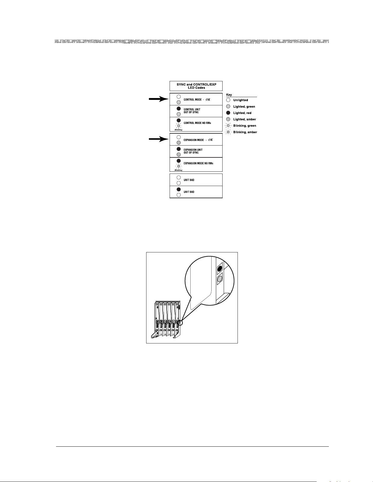
Install ing Multiple Carriers Model 117A4 Carrier Installati on Instructions
3
At this stage of your installation, the LE Ds di splayed should match the first or
fourth lines of th e SYNC and CONTROL/EXP LED Codes label.
4
If an OUT OF SYNC LED is lit, power down, wa it at least 15 seconds, and then
repower the carr ie rs in or der from le ft to rig ht, as described in Step 8 in
“Inst al li n g a Si ng l e Ra d io M od u le in Eac h Car r i er.” If the LED is s t il l li t, call
Customer Suppor t as described on the inside fr ont cover of this book.
OUT OF S YNC
CONTROL/
T
4
1 2 3 4
RANSTALK
21
O N
21
O N
5
EXPANSION
N
A
H
R
T
P
A
E
O
N
N
R
M
G
R
E
T
P
A
H
K
O
-
E
T
I
C
A
R
P
E
R
U
R
M
A
F
T
R
E
X
O
L
N
E
I
R
A
L
K
M
U
S
P
I
M
E
R
O
L
K
O
-
E
T
I
C
A
R
P
E
R
U
R
M
A
F
T
R
E
X
O
L
N
E
I
R
A
L
K
M
U
S
P
I
M
E
R
O
L
K
O
-
E
T
I
C
A
R
P
E
R
K
O
-
E
T
I
C
A
R
P
E
R
N
TIO
U
A
C
Y
L
N
O
E
SE
L
U
B
A
6
T C
89
T&
A
667
47
8
⁄N
P
IN
T
OU
C
N
Y
S
F
O
OUT
6
Model 117A4 Car rier Installa tion Instructions
503-801-180
Issue 2 February 1999 35
Page 42
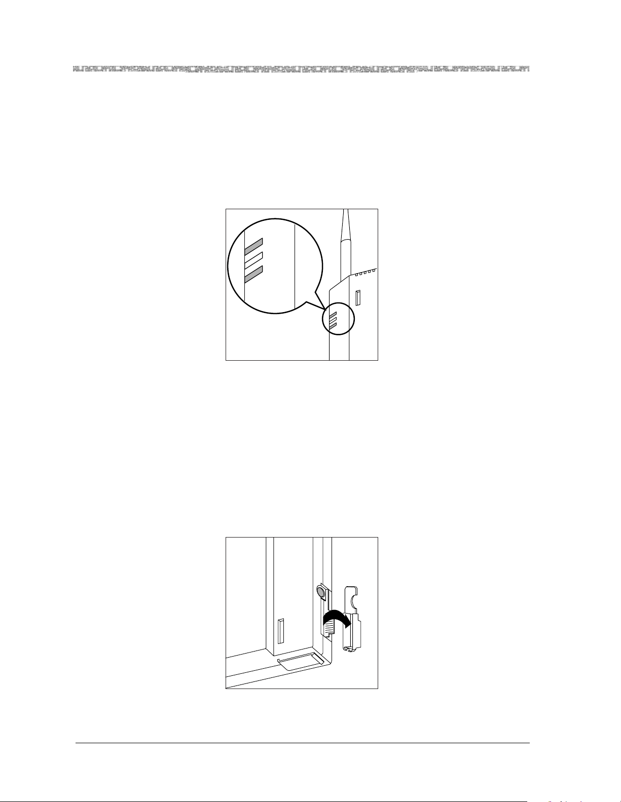
Model 117A4 Carrier Installation Instructions Installing Multiple Carriers
5
The PASS and POWER LEDs on all radio modules should be lit and green. If a
radio module’s PASS LED is not lit:
a
Power down the carriers.
b
Unplug from the wall outl et the power cord/AC adapter of the radio module
that did not light.
c
Wait 15 seconds.
d
Plug in the radio module’s power cord again.
e
Repower the carriers again, following the proper le ft-to-right order.
POWER
RADIO
PASS
Radio
Module
POWER
RADIO
PASS
6
If your LEDs matc h th e patt ern in the il lust ration in St ep 2 , you c an fee l conf i dent
that th e carriers are cabled corr ectly and that the installed radio modules are all
functional.
7
Now go on to "Instal ling the Remaining Ra dio Modules" (page 36).
Installing the Remaining Radio Modules
1
Power down the carriers.
2
Remove the plastic cap covering each radio module’s card edge before inserting
the radio modules into the carriers.
Model 117A4 Car rier Installa tion Instructions
503-801-18036 Issue 2 February 1999
Page 43

Install ing Multiple Carriers Model 117A4 Carrier Installati on Instructions
3
Beginning with the first em pty slot and working from left to right, insert a rad io
module into each slot of the control carrie r. Hook each radio module onto a
mounting rod. Slowly swing the radio module’s card edge into the card edge
connector on the back of the carrier.
Note:
Slot 6 of a Model 117A3 control carri er m us t always contain a radio
module to pass the synchronization sig nal to the next carrier.
A Model 117A4 carrier does not require Slot 6 to be filled.
4
When the card edge is ful ly sea ted, a snap lock on the botto m of t he radio modul e
will engage.
5
Repeat Steps 3 and 4 for each expansion carrier, until each radio module is
inserted into a carrier.
Note:
Fill all six slots of the current carrier before inserting radio modules into
the next carrier.
Model 117A4 Car rier Installa tion Instructions
503-801-180
Issue 2 February 1999 37
Page 44

Model 117A4 Carrier Installation Instructions Installing Multiple Carriers
6
Insert a telephone line cord into the bottom of each radio module.
7
Slide the tele phone line cords through t he ca ble manager slot on the left front of
the car rier.
Model 117A4 Car rier Installa tion Instructions
503-801-18038 Issue 2 February 1999
Page 45
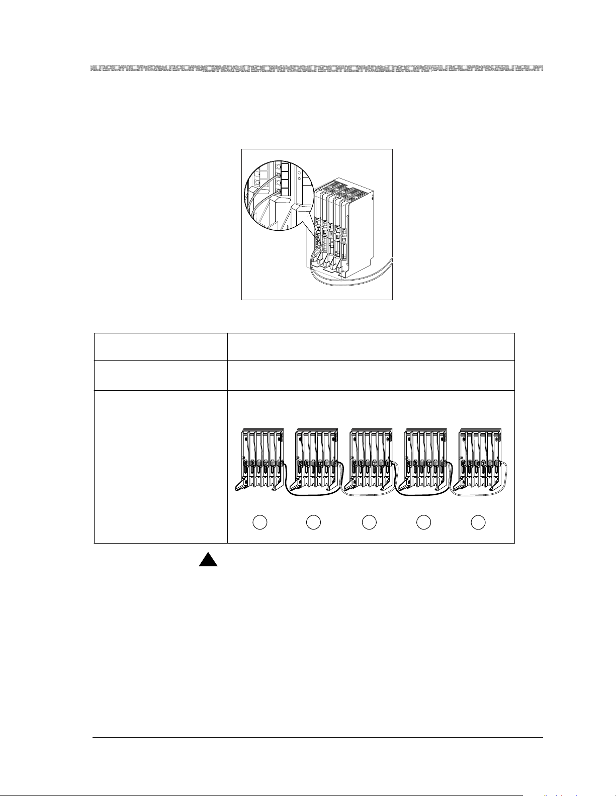
Install ing Multiple Carriers Model 117A4 Carrier Installati on Instructions
MUSIC
ON
HOLD
N
S
I
O
N
S
X
T
E
N
S
I
O
N
S
8
Insert the free end of each telephone line cord into the appropriate extension jack
or termina l/st ation con nector on y our communi cati ons sys tem switch/c ont rol unit
(refer to your communications system manual for the prope r location).
PFT
L
I
N
PFT
E
L
S
I
N
PFT
E
L
PAGE
S
I
N
PFT
E
L
SMDR
S
I
N
PFT
E
L
S
I
N
206
MODULE
E
S
PFT
206
MODULE
PFT
PROCESSOR
E
MODULE
X
T
400
E
E
MODULE
X
N
T
S
400
VOL
E
MODULE
I
N
O
S
N
E
I
S
X
MUSIC
O
ON
T
N
HOLD
E
E
S
X
N
T
S
E
I
N
O
S
N
I
S
O
N
S
9
Power the carriers as follows:
If the c a rriers are
plugged into... Then...
One surge suppressor strip Power the strip
Result: All carriers will turn on sim u ltaneously.
Wall outlets Plug in the power for the Carriers in this order:
T
!
CAUTION:
21
O N
1 2 3 4
Control
Carrier
1
RANSTALK
N
A
H
TR
P
A
E
O
N
N
R
M
G
R
TE
P
A
H
K
-O
ITE
C
A
R
P
E
R
U
R
M
A
TF
R
E
X
LO
N
IE
R
LA
K
M
U
S
IP
EM
R
O
L
K
-O
ITE
C
A
R
P
E
R
U
R
M
A
TF
R
E
X
O
L
N
IE
R
LA
K
M
U
S
IP
M
E
R
LO
K
ITE-O
C
A
R
P
E
R
K
-O
E
IT
C
A
R
EP
R
N
UTIO
CA
LY
N
O
E
E
S
L
U
21
B
A
C
6
T
O N
T&
A
84766789
⁄N
P
IN
T
U
O
C
N
Y
S
F
O
T
U
O
5
1 2 3 4
6
Expansion
Carrier #1
T
RANSTALK
N
A
H
TR
P
A
E
O
N
N
R
M
G
R
TE
P
A
H
K
-O
ITE
C
A
R
P
E
R
U
R
M
A
TF
R
E
X
LO
N
IE
R
LA
K
M
U
S
IP
EM
R
O
L
K
-O
ITE
C
A
R
P
E
R
U
R
M
FA
T
R
E
X
O
L
N
IE
R
LA
K
M
U
S
IP
M
E
R
LO
K
ITE-O
C
A
R
P
E
R
K
-O
E
IT
C
A
R
EP
R
N
TIO
U
21
O N
CA
Y
L
N
O
E
E
S
L
U
21
B
A
C
T
96
&
O N
T
A
6678
7
84
⁄N
P
IN
T
U
O
C
N
Y
S
F
O
T
U
O
5
1 2 3 4
6
Expansion
Carrier #2
2 3
T
RANSTALK
N
A
H
TR
P
A
E
O
N
N
R
M
G
R
TE
P
A
H
K
-O
ITE
C
A
R
P
E
R
U
R
M
A
TF
R
E
X
LO
N
IE
R
LA
K
M
U
S
IP
M
E
R
O
L
K
-O
ITE
C
A
R
P
E
R
U
R
M
A
TF
R
E
X
O
L
N
IE
R
LA
K
M
U
S
IP
M
E
R
LO
K
-O
ITE
C
A
R
P
E
R
K
-O
ITE
C
A
R
EP
R
N
UTIO
21
O N
21
O N
5
21
CA
O N
Y
L
N
O
E
E
S
L
U
B
A
C
T
T&
A
47667896
8
⁄N
P
IN
T
U
O
C
N
Y
S
F
O
T
U
O
1 2 3 4
6
Expansion
Carrier #3
Never connect or disconnect expansion cables or telephone line cords, or insert or
remove radio modules, while the carrier is plugged into the wall outlet.
10
Now go to "Installation Self Test for Remaining Radio Modules" (page 40).
T
RANSTALK
N
A
H
TR
P
A
E
O
N
N
R
M
G
R
TE
P
A
H
K
-O
ITE
C
A
R
P
E
R
U
R
M
A
TF
R
E
X
O
L
IEN
R
LA
K
M
U
S
IP
EM
R
O
L
K
-O
ITE
C
A
R
P
E
R
U
R
M
A
TF
R
E
X
O
L
N
IE
R
LA
K
M
U
S
IP
M
E
R
LO
K
-O
ITE
C
A
R
P
E
R
K
-O
ITE
C
A
R
P
E
R
N
UTIO
CA
LY
N
O
E
S
LE
U
21
B
A
T C
96
&
O N
T
A
6678
847
⁄N
P
IN
T
U
O
C
N
Y
S
F
O
T
U
O
5
6
1 2 3 4
T
RANSTALK
N
A
H
R
PT
A
E
O
N
N
R
M
G
R
E
T
P
A
H
K
-O
ITE
C
A
R
P
E
R
U
R
M
A
TF
R
E
X
O
L
N
IE
R
A
L
K
M
U
S
IP
M
E
R
LO
K
E-O
IT
C
A
R
P
E
R
U
R
M
TFA
R
E
X
LO
N
IE
R
LA
K
M
U
S
IP
M
E
R
LO
K
-O
E
IT
C
A
R
P
E
R
K
-O
ITE
C
A
R
EP
R
N
UTIO
21
CA
O N
Y
L
N
O
E
E
S
L
U
21
B
A
C
T
&
O N
T
7896
A
66
47
8
⁄N
P
IN
T
U
O
C
N
Y
S
F
O
T
U
O
5
6
Expansion
Carrier #4
4
5
Model 117A4 Car rier Installa tion Instructions
503-801-180
Issue 2 February 1999 39
Page 46
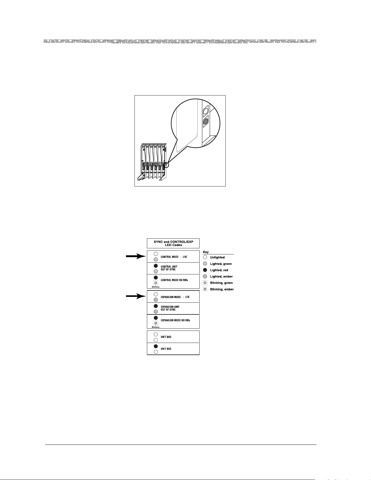
Model 117A4 Carrier Installation Instructions Installing Multiple Carriers
Installation Self Test for Remaining Radio Modules
1
Wait a few second s after po wering the carriers, th en veri fy that the carriers ’ OUT
OF SYNC LEDs are not lit.
OUT OF S YNC
CONTROL/
T
4
1 2 3 4
2
At this stage of you r install at ion, the LEDs displa yed shou ld agai n matc h the f irst
or fourth lines of the SYNC and CONTROL/EXP LED Codes label, depending
on whether the carrier is the control or an expansion carrier. (Keep in mind that a
Model 117A3 carrier does not have a CONTROL/EXPANSION LED.)
RANSTALK
21
O N
21
O N
5
EXPANSION
N
A
H
R
T
P
A
E
O
N
N
R
M
G
R
E
T
P
A
H
K
O
-
E
T
I
C
A
R
P
E
R
U
R
M
A
F
T
R
E
X
O
L
N
E
I
R
A
L
K
M
U
S
P
I
M
E
R
O
L
K
O
-
E
T
I
C
A
R
P
E
R
U
R
M
A
F
T
R
E
X
O
L
N
E
I
R
A
L
K
M
U
S
P
I
M
E
R
O
L
K
O
-
E
T
I
C
A
R
P
E
R
K
O
-
E
T
I
C
A
R
P
E
R
N
TIO
U
A
C
Y
L
N
O
E
E
S
L
U
B
A
C
6
T
89
&
7
T
6
A
76
4
8
⁄N
P
IN
OUT
F SYNC
O
UT
O
6
Model 117A4 Car rier Installa tion Instructions
503-801-18040 Issue 2 February 1999
Page 47
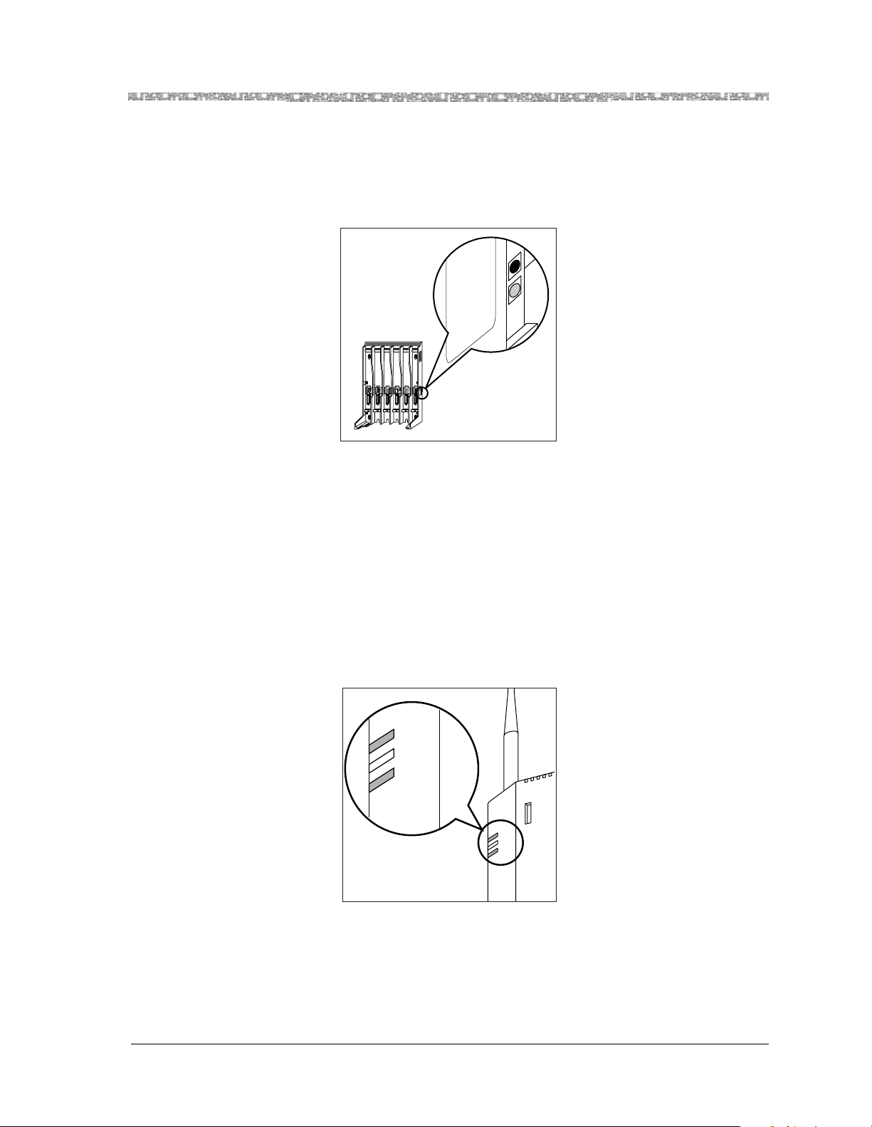
Install ing Multiple Carriers Model 117A4 Carrier Installati on Instructions
3
If an OUT OF SYNC LED is lit, power down, wa it at least 15 seconds, and then
repower the carr ie rs in or der from le ft to rig ht, as described in Step 9 in
“Installing the Remaini ng Radio Modules.” If the LED is still lit, cal l Customer
Support as described on the inside front cover of this book.
OUT OF S YNC
CONTROL/
T
4
1 2 3 4
4
The PASS and POWER LEDs on all radio modules should be lit and green,
indicating that all of the radio modules are functional. If a radio module’s PASS
LED is not lit:
RANSTALK
21
O N
21
O N
5
EXPANSION
N
A
H
R
T
P
A
E
O
N
N
R
M
G
R
E
T
P
A
H
K
O
-
E
T
I
C
A
R
P
E
R
U
R
M
A
F
T
R
E
X
O
L
N
E
I
R
A
L
K
M
U
S
P
I
M
E
R
O
L
K
O
-
E
T
I
C
A
R
P
E
R
U
R
M
A
F
T
R
E
X
O
L
N
E
I
R
A
L
K
M
U
S
P
I
M
E
R
O
L
K
O
-
E
T
I
C
A
R
P
E
R
K
O
-
E
T
I
C
A
R
P
E
R
N
TIO
U
A
C
Y
L
N
O
E
S
LE
U
B
A
T C
96
&
8
T
7
A
66
47
8
⁄N
P
IN
OUT
C
YN
F S
OUT O
6
a
Power down the carrie r s .
b
Unplug from the wall outlet the po wer cord/AC ada pter of the radio module
that did not light.
c
Wait 15 seconds .
d
Plug in the radio module’ s power cord again.
e
Repower the carriers again, following the proper left-to-right order.
If the LED is still not lit, call Customer Support as described on the inside
front cover of this book.
POWER
RADIO
PASS
Radio
Module
POWER
RADIO
PASS
Model 117A4 Car rier Installa tion Instructions
503-801-180
Issue 2 February 1999 41
Page 48

Page 49

A Warran ty and Repair Information
Lucent Technologies Limited Warranty and Limitation of Liability
Lucent Technologies warrants to you, the customer, that your wireless telephone system will be in good working
order on the date Luc ent Technologie s or its Authorize d Dea ler delivers or installs the system, whichever is later
(“Warranty Date”). If you notify Lucent Technologies or its Authorized Dealer within one year of the Warranty
Date that your system is not in good working order, Lucent Technologies will without charge to you repair or
replace, at i ts opt ion , the sys tem compone nts th at are not i n good working ord er. Repair or replacement pa rts may
be new or refurbished and will be prov ided on an exchange basis. If Lucent Technologies determines tha t your
system cannot be repai red or replaced, Lucent Technologies will remove the system and, at your option, refund
the purchase price of your sys tem or apply the purchase price towards the purchase of another Lucent
Technologi es sy stem.
If you purchased your system directly from Lucent Technologies, Lucent Technologies will perform warranty
repair in accordance with the terms and conditions of the specific type of Lucent Technologies maintenanc e
coverage you selected. A written explanation of Lucent Technologies’s types of maintena nce coverage may be
obtained from Lucent Technologies by calling 1 800 247-7000 (in the continental U.S. only). If you purchased
your system from an Lucent Technologies Authorized Dealer, contact your dealer for the details of the
maintenance plan applicable to your system.
This Lucent Technologies limited warranty covers damage to the system caused by power surges . Unless
otherwise expressly agreed to in a writ ten agreement signed by Lucent Technologies, Lucent Technologies will
not be responsible under this limited warranty for damages resulting from:
•
Failure to follow Lucent Technologies’s install ation, operation, or maintenance
instructions;
•
Unauthorized system modification, movement, or alteration;
•
Unauthorized use of common carrier communication services accessed through
the system;
•
Abuse, misuse, or negligent acts or omissi ons of the customer an d pers ons under
the customer’s control; or
•
Acts of third parties and acts of God. LUCENT TECHNOLOGIES’S
OBLIGATION TO REPAIR, REPLACE, OR REFUND, AS SET FORTH
ABOVE, IS YOUR EXCLUSIVE REMEDY.
EXCEPT AS SPECIFICALLY SET FOR TH ABOVE, Lucent Technologies, I TS AFFILIATES,
SUPPLIERS , AND D EALERS MAKE NO WARRANTIES, EXPRESS OR IMPLIED, AND
SPECIFICALLY DISCLAIM ANY WARRANTIES OF MERCHANTABILITY OR FITNESS FOR A
PARTICULAR PURPOSE.
Model 117A4 Carrier installation Instructions
503-801-180
Issue 2 February 1999 43
Page 50

A
Warranty and Repair I nfor m ation Repair Informat ion
Limitation of Liability
Except as provided below, the liability of Lucent Technologies and its affiliates and suppliers for any claims,
losses, damages, or expenses from any cause whatsoever (including acts or omissions of third parties), regardless
of the form of actio n, w hether i n contract, tor t, or oth erwis e, shall not ex ceed t he less er of: (1) the direct damages
proven; or (2) the repair cost, replacement cost, license f ee, annual rental charge, or purchase price, as the case
may be, of the equipment that dir ectly gi ves rise to the cl aim. Except as provided below, Lucent Technologies and
its affiliates and suppliers shall not be liable for any incidental, special, reliance, consequential, or indirect loss
or damage incurred in connection with the equipment. As used in this paragraph, consequential damages
include, b ut a r e not li mite d to, t he followi ng: l ost p r o f it s, l ost revenues, and losses aris ing out o f un autho riz ed use
(or charges for such use) of common carr ier telecommunic ations services or faciliti es accessed through or
connected to the equipment. For personal inju ry caused by Lucent Technologies’s negligence, Lucent
Technologies’s liability shall be limited to proven damages to person. No acti on or procee ding against Lucent
Technologies or its affiliates or suppliers may be commenced more than twenty-four (24) months after the cause
of action accrues. THIS PA RAGRAPH SHALL SURVIVE FAILURE OF AN EXCLUSIVE REMEDY.
Repair Information
Outside the continental U.S., contact your Lucent Technologies Representative or local Authorized Dealer for
warranty and repair information applicable to your syste m.
In-Warranty Repairs
If you purchased or lease d your sy st em directly from Lucent Technologies, Lucent Technologies will repair it
free of charge during the one-year warranty period. Simply call for custome r support as instructed on the inside
front cover of this book.
Business-Da y service is standard during the warranty period. Business-Day serv ice is performed during normal
business hours. (Around-the-Clock service is not available for phones.)
If you purchased or leased your system through a Lucent Technologies Authorized Deal er, contact your dealer
for repairs.
Po st- Warranty Repairs
If you purchased the sy st em fr om Lucent Technologi es and you have a post-w arranty service contract, Lucent
Technologi es service is provide d under the terms of that contract.
To significantly reduce unexpe cted repair costs after the warranty period, you can purchase a post-warranty
service contra ct from Lucent Technologies. If you do not have a contra ct, Lucent Technologies service is
provided on a time-and-materials basis by calling for customer support as instructed on the inside front cover of
this book. A contract provides to you, within the applicable coverage period and response times, service calls
with no charge for parts and labor on covered repairs. To order a post-warranty service contract,
call 1 800 247-7000 (in the continental U.S. only).
If you leased your system from Lucent Technologies, Business-Day service is included in your lease.
If you purchased or leased your system through a Lucent Technologies Authorized Dealer, contact your dealer
for repairs.
Model 117A4 Carrier installation Instructions
503-801-18044 Issue 2 February 1999
Page 51

B Regulatory Information
This appendix contains infor ma tion about the Federal Communications Commission and Industry Canada.
FCC Part 15 Rules
The Lucent Technologies MDW telephone products have been tested and have been found to comply with FCC
Part 15 Rules. These sp ecifications are des igned to provi de reasonable protection against harmful interference in
a commercial or residential installation. This wireless telephone product generates, uses , and can radiate radio
frequency e nergy and, if not in stalled and used in accordance with the instructions, may cause harmful
interference to radio communications. However, there is no guarantee that interference will not occur in a
particula r inst allat io n. If the t elepho ne does cause harmfu l inte rfer ence to ra dio or t ele vis ion rec eptio n, wh ich ca n
be determined b y turning the teleph one of f and on, the use r is encourag ed to tr y to correc t the inte rference b y one
or more of the following measures:
•
Where it can be done safely, reorient the receiving television or radio ante nna.
•
T o the ex te nt p ossi ble , relo cate th e t ele v ision , r adi o, or ot her rec ei v er with re spec t
to the telephone.
•
Plug the telephone into an electri cal outlet that is not on the same circuit as one
used by the radio or television.
IC RSS-210 Compliance
This device complies with RSS-210 of Industry Canada. Operation is subject to the following two conditions:
1
This device may not cause interference.
2
This device must accept any interference including interference that may cause
undesirable operation of the device.
The user is cautioned that modif ications to this telephone, not expressly approved by L ucent Technologies,
could void the user’s authority to operate the equipment.
Model 117A4 Car rier Installa tion Instructions
503-801-180
Issue 2 February 1999 45
Page 52

Page 53

General
C Specifications
Model:
Dimensions
and Weights:
Operating
Temperature
Electrical
Specifications:
(Power)
Electrical
Requirements
117A4 Carrier
Carrier 14.0"(L) x 2.5"(H) x 9.0"(W)
35.56 x 6.35 x 22.86 cm
Carrier w/6 RMs 14.0"(L) x 2.5"(H) x 9.0"(W)
35.56 x 6.35 x 22.86 cm
Power Supply 5.13"(L) x 1.6"(H) x 1.6"(W)
13.03 x 4.06 x 4.06 cm
Temperature range:
Relative Humidity:
Carrier w/6 RMs
Power supply
•
105–130VAC, 50–60 Hz, 3-prong outlet separate ground, separately fused
at 15 amps .
•
Outlet must not be controlled by an on/off switch
•
Grounding to comply with Underwriters Laboratories (UL) 1459
4.4° C (40° F) to 40° C (104° F)
15% to 95%
24.0 watts
30.0 watts (9V)
3.00 lbs
1.36 kgs
12.00 lbs
5.44 kgs
1.70 lbs
0.77 kgs
Model 117A4 Car rier Installa tion Instructions
503-801-180
Issue 2 February 1999 47
Page 54

 Loading...