

Page 1

CALLMASTER® V Telephone Console
User’s Guide
The CALLMASTER V Telephone Console. . . . . . . . . . . . . 1
Headset Connections with the CALLMASTER V. . . . . . 2
Compatible Headpieces. . . . . . . . . . . . . . . . . . . . . . . . . . 3
The CALLMASTER V Recorder Interface . . . . . . . . . . . . 3
The Softkeys. . . . . . . . . . . . . . . . . . . . . . . . . . . . . . . . . . . 3
Using the Softkey Feature Menus. . . . . . . . . . . . . . . . . . 4
Other Softkey Features That May Be On Your Display. 4
Call-Handling Features . . . . . . . . . . . . . . . . . . . . . . . . . . . . 4
Getting Messages . . . . . . . . . . . . . . . . . . . . . . . . . . . . . . . . 7
Selecting a Personalized Ring . . . . . . . . . . . . . . . . . . . . . . 8
Voice and Display Features . . . . . . . . . . . . . . . . . . . . . . . . 8
Operating Range Requirements. . . . . . . . . . . . . . . . . . . . . 9
Telephone Installation. . . . . . . . . . . . . . . . . . . . . . . . . . . . . 9
Important Safety Warnings for Installation . . . . . . . . . 10
Desktop Installation. . . . . . . . . . . . . . . . . . . . . . . . . . . . 11
Wall Installation . . . . . . . . . . . . . . . . . . . . . . . . . . . . . . . 12
Installing the Designation Card . . . . . . . . . . . . . . . . . . 13
Orderable Cards and Equipment . . . . . . . . . . . . . . . . . 14
555-233-735
Comcode 108488222
Issue 1
September 1999
Page 2

CALLMASTER® V Telephone Console User’s Guide
NOTICE
While reasonable efforts were made to ensure that the information in this
document was complete and accurate at the time of printing, Lucent
Technologies can assume no responsibility for any errors. Changes or
corrections to the in form ati on co ntai ned in this document may be in cor pora t ed
into future issues.
TO ORDER COPIES OF THIS DOCUMENT
Contact: Lucent Technologies BCS Publications Center
Order: Document No. 555-233-735
HEARING AID COMPATIBILITY
2855 N. Franklin Road
Indianapolis, IN 46219
Domestic: 1 800 457-1235 International: 1 317 322-6791
Domestic Fax: 1 800 457-1764 International Fax: 1 317 322-6699
Issue 1, September 1999
The CALLMASTER V telephone console is Hearing Aid Compatible (HAC)
when used with HAC headse ts, and thus all units have “HAC” printe d on th em .
YOUR RESPONSIBILITY FOR YOUR SYSTEM’S SECURITY
Y ou are res ponsi ble for the s ecurity of your sy stem. Lucent Technologies does
not warrant that this product is immune from or will prevent unauthorized use
of common-carrier telecommunication services or facilities accessed through
or connected to it. Luce nt Technologies will not be re spons ible fo r any c harges
that result from such unauthorized use. Product administration to preve nt
unauthorized use is your responsibility and your system manager should read
all documents provided with this product to fully understand the features
available that may reduce your risk of incurring charges.
TRADEMARKS
DEFINITY, AUDIX, and CALLMASTER are registered trademarks of Lucent
Technologies.
Mirage, Star Set, and Supra are registered trademarks of Plantronics, Inc.
FCC REGULATIONS
The FCC requires us to provide the following warning for Class B residential
installations.
WARNING: This equipment has been tested and found to comply with the
limits for a Class B digital dev ice, purs uant to Part 15 of the FCC Ru les. These
limits are designed to provide reasonable protection against harmful
interference in a residential installation. This equipment generates, uses, and
can radiate radio frequency energy and, if not installed and used in
accordance with the instructions, may cause harmful interference to radio and
television communications. However, there is no guarantee that interference
will not occur in a particular installation. If this equipment does cause harmful
interference to radio or television reception, which can be determined by
turning the equipment off and on, the user is encouraged to try to correct the
interference by one or more of the following measures:
• Reorient or relocate the receiving antennae.
• Increase the separation between the equipment and receiver.
• Connect the equipment into an outlet on a circuit different from that
to which the receiver is connected.
• Consult the dealer or an experienced radio/tv technician for help.
ii
Page 3

CALLMASTER® V Telephone Console User’s Guide
OBTAINING PRODUCTS
To learn more about Lucent Technologies products and to order any of these
products, contact Lucent Direct, the direct-market organization of Lucent
Technologies Business Communications System. Access their web site at
www.lucentdirect.com or call the following numbers: customers should call
1 800 451-2100 or account executives can contact Lucent Direct at
1 800 778 1880 (voice) or 1 800 778-1881 (fax).
THE “CE” MARK
If the “CE” mark is affixed to this equipment. it means that it conforms to the
European Union Electromagnetic Compatibility Directive (89/336/EEC) and
the Low Voltage Directive (73/23/EEC).
Prepared by © 1999 Lucent Technologies
BCS Product Publications All Rights Reserved
Middletown, New Jersey 07748-1998 Printed in USA
IMPORTANT USER SAFETY
INSTRUCTIONS
iii
The most careful attention has been devoted to quality standards in the
manufacture of your new telephone. Safety is a major factor in the design of
every set. But, safety is YOUR responsibility too.
Please read carefully the hel pful tip s liste d below and on the next pa ge. Thes e
suggestions will enable you to take full advantage of your new voice terminal.
Then, retain these tips for later use.
!
CAUTION:
This telephone is NOT for residential use. It is for business systems
applications ONLY. It will NOT operate on public networks. It MUST
BE connected to a DEFINITY Enterprise Communications Server.
Use in a residential environment could result in an electrical short
circuit when the telephone wiring is set up to provide other
applications, for example, for appliance control or power
transformers. The AC power us ed in these ap plica tions may create a
safety hazard by placing a direct short circuit across the telephone
wiring.
Use
When using your telephone equipment, the following safety precautions
should always b e follow ed to re duce the risk of fir e, ele ctric shoc k, and i njury to
persons.
• Read and understand all instructions.
• Follow all warnings and instructions marked on the telephone.
Page 4

CALLMASTER® V Telephone Console User’s Guide
This telephone can be hazardous if immersed in water. To avoid the
•
possibility of electric shock, do not use it while you are wet. If you
accidentally drop the tel ephon e into w ater, do not retrieve it until you have
first unplugged the line cord from the modular wall jac k. Then, call se rvice
personnel to ask about a replacement.
• Avoid using the telephone d uring ele ctrical storms i n your i mmediate area.
There is a risk of electric shock from lightning. Urgent calls should be
brief. Even though protective measures may have been installed to limit
electrical surges from entering your business, absolute protection from
lightning is impossible.
• If you suspect a natural gas leak, report it immediately, but use a
telephone away from the area in question. The telephone’s electrical
contacts could generate a tiny spark. While unlikely, it is possible that this
spark could ignite heavy concentrations of gas.
• Never push objects of any kind into the equipment through housing slots
since they may touch hazardous voltage points or short out parts that
could result in a risk of electric shock. Never spill liquid of any kind on the
telephone. If liquid is spilled, however, refer servicing to proper service
personnel.
• To reduce the risk of electric shock, do not disassemble this telephone.
There are no user serviceable parts. Opening or removing covers m ay
expose you to hazardous voltages. Incorrect reassembly can cause
electric shock when the telephone is subsequently used.
Service
1. Before cleaning, unplug the telephone from the modular wall jack. Do
not use liquid cleaners or aerosol cleaners. Use a damp cloth for
cleaning.
2. Unplug the telephone from the modular wall jack. Be sure to refer
servicing to qualified service personnel when these conditions exist:
— If liquid has been spilled into the telephone.
— If the telephone has been exposed to rain or water.
— If the telephone has been dropped or the housing has been
damaged.
— If you note a distinct change in the performance of the telephone.
iv
SAVE THESE INSTRUCTIONS
When you see this wa rning sym bol on the p roduct, refer
!
to this instructions booklet packed with the product for
more information before proceeding.
Page 5
CALLMASTER® V Telephone Console User’s Guide 555-233-735 Issue 1
The CALLMASTER V Telephone Console 1
The CALLMASTER V Telephone Console
The CALLMASTER® V telephone has b een spec ially desig ned for use with the
Automatic Call Distribution (ACD) system and the many features of the
DEFINITY® Enterprise Communications Server (ECS) and the DEFINITY
Communications System Generic 1, Generic 2, and Generic 3. This
telephone is designed to be use d wi th a hea dse t i n a 2-wir e en vironment.
Note: Power for the CALLMASTERV telephone, including the headset,
comes from the DEFINITY switch through the 2-wire DCP line.
The CALLMASTER V also has a built-in Recorder Interface which allows you
to connect the telephone to a recordin g dev ic e so that you can reco rd a ll v oic e
interactions. For more information about this interface, see “The
CALLMASTER V Recorder Interface” on page 3.
Note: The tape recorder used with the CALLMASTER V telephone must be
not
purchased by the user; it is
provided with the telephone.
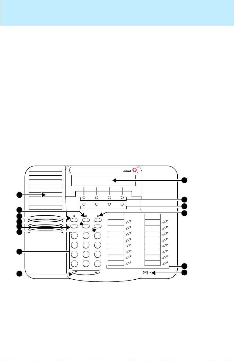
Figure 1 below shows a front view of the CALLMASTER V telephone. The
features of the telephone are explained after the figure.
Note: For a rear view of the telephone, see Figure 4 on page 9.
®
1
2
3
4
5
6
7
CALLMASTER V
8
Menu Exit Prev Next
Speaker
Mute Hold
Redial
Transfer
Conf
Test
Ring
DEF
ABC
GHI
PQRS
1
4
7
*
3
2
MNOJKL
56
TUV
WXYZ
8
9
#
O
Volume
Tel #
FIGURE 1 The CALLMASTER V Telephone Console, Front View
9
10
11
12
13
14
Page 6
CALLMASTER® V Telephone Console User’s Guide 555-233-735 Issue 1
The CALLMASTER V Telephone Console 2
The following features correspond to the numbers in Figure 1.
1) Telephone Notepad 8) Volume control button
2) Mute (or ) button 9) Display
3) Speaker (or ) button 10) Softkeys
4) Transfer/Test (or ) button 11) Display control buttons
5) Redial (or ) button 12) Hold (or ) button
6) Conf/Ring (or ) butto n 13) Call appearance/ fe at ur e buttons
(See Note immediately below)
7) Dial pad 14) Message light — labeled
Note: Two feature buttons must be administered in the following ways:
• One of the feature buttons must be designated as the
Headset On/Off button;
• The Release feature must be administered on a second feature
button.
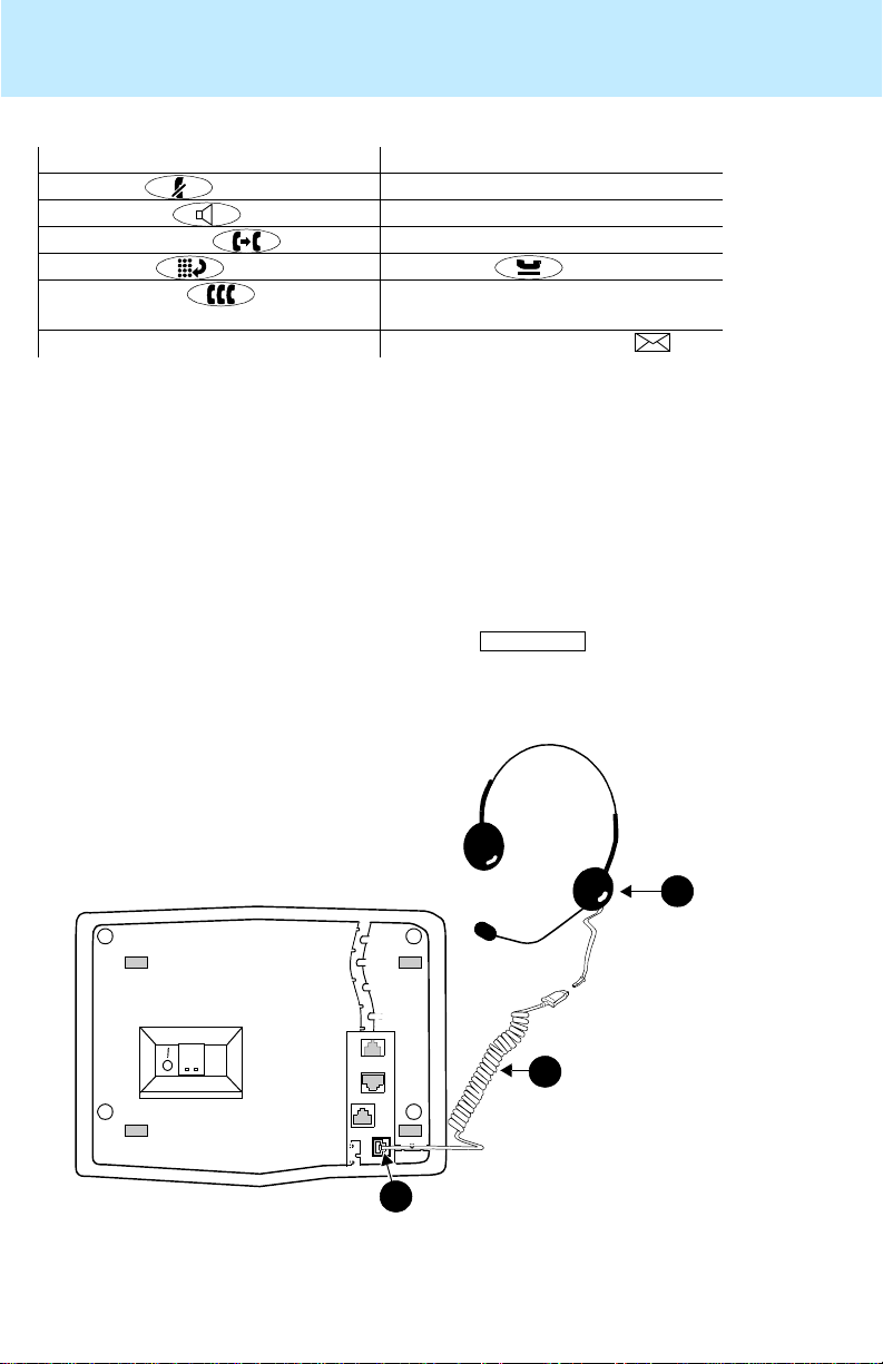
Headset Connections with the CALLMASTER V
The headset connection for the CALLMASTER V consists of a headpiece
(shown as 1 in Figure 2 below) which is plugged into an adapter cord (shown
as 2).
Note: Your system manager MUST administer a button on your
set. Use this button to turn your headset on and off. For instructions for
using this feature button, see “Headset On/Off” in the section titled
Call-Handling Features.
Headset On/Off
1
2
3
FIGURE 2 The Headset Connecte d to On e of the Headset Jacks (sho wn
as 3) on the CALLMASTER V Telephone
Page 7

CALLMASTER® V Telephone Console User’s Guide 555-233-735 Issue 1
The CALLMASTER V Telephone Console 3
Compatible Headpieces
The following Lucent Technologies headpieces can be used with these
telephones:
®
— Mirage
— Receiver fits over either ear. Not for noisy environments.
— StarSet® — Eartip fits in ear canal.
— Supra® — Adjustable headband and soft ear cushion.
— Encore
®
— Advanced sound technology with adjustable headband
and soft ear cushion.
— TriStar
®
— Advanced headpiece which fits over the ear.
The CALLMASTER V Recorder Interface
The CALLMASTER V’s R ecorder In terface is desig ned for r eco rding cal ls on a
standard tape recorder. (A recorder with AGC [Automatic Gain Control] is
recommended.) With th is interfa ce, a warni ng tone, a soft beep rep eated ev ery
13.5 seconds, notifies the agent and the calling party that the call is being
recorded.
IMPORTANT: The use of service observing features and call recording
features may be subject to federal , state, and local law s, rules, or regulations
and may be prohibited pursuant to the laws, rules, or regulations or require
the consent of one or both of the parties to the conversation. Customers
should familiarize them selves with and comply with all applicable laws , rules,
and regulations before using these features.
Be aware that this tone may be a legal requirement.
The Softkeys
The softkeys are the four unlabeled round keys located directly below the
display. The four ro un d di sp lay c ont rol buttons, labeled Menu , Exit , Prev, and
Next are located under the softkeys. See Figure 3.
Display
Softkeys
NextPrevMenu Exit
FIGURE 3 The Display, Softkeys, and Display Control Buttons
Display
control buttons
Page 8

CALLMASTER® V Telephone Console User’s Guide 555-233-735 Issue 1
Call-Handling Features 4
Using the Softkey Feature Menus
There are three separate softkey feature menus. Each of these menus allows
you to select from four different features.
You can enter Softkey Mode (and view the softkey feature menu) by pressing
the display control button labeled Menu or . The following is an example
of a softkey feature menu.
Dir Drop HFAns Timer
The top line of each softkey feature menu screen shows you the status of
each of the four features. An arrow appears above the feature name or
abbreviation if that feature is active. In the above example, the arrow above
the Timer feature indicates that feature is active.
The second line on each softkey feature menu shows the features you can
access. To use any of these fe atures, you must p ress the softkey b elow the
feature name or abbreviation.
Press the Next or Prev button unti l the fe ature y ou want to use appe ars on the
display.
Note: An error tone (one beep) sounds when you have made an
inappropriate softkey entry.
Press the Exit button at any time to exit the softkey feature menus a nd
return to normal call-handling operation.
Other Softkey Features That May Be On Your Display
There are 12 default features that can be accessed with the softkeys on a
CALLMASTER V telephone. However, the system manager may substitute
other softkey features in their place.
Call-Handling Features
HEADSET ON/OFF
The system administra tor shoul d have admi nistered a button on
your CALLMASTER V telephone.
To turn on your headset
1. Press .
Headset On/Off
The green light next to the button goes on to remind you the headset is
active.
To turn off your headset
1. Press again.
Headset On/Off
Headset On/Off
Page 9

CALLMASTER® V Telephone Console User’s Guide 555-233-735 Issue 1
Call-Handling Features 5
The green light next to the button goes off.
CONFERENCE
The Conference feature allows you to conference up to six parties (including
yourself) on a call.
To add another party to a call (for a total of six parties)
1. Press (or
Conf
2. Dial the number of the new party and wait for an answer.
3. When you want to add the new person, press (or
again.
4. Repeat Steps 1 through 3 for additional conference connections.
To add a call you have put on hold to another call you are connected to
1. Press (or
Conf
2. Press the call appearance button of the call on hold (first call).
3. Press (or
Conf
To drop the last person added to the conference call
1. With a display: Press the Menu button and then press the softkey
below Drop.
Without a display: Press the button (if administered).
). [dial tone]
). [dial tone]
) again.
Drop
Conf
)
HOLD
The Hold feature puts a call on hold until you can return to it.
To put a call on hold while you answer another call or perform another
task
1. Press (or
Hold
).
To answer a new call while active on another
1. Press (or ).
Hold
2. Press the call appearance button of the incoming call.
To return to the held call
1. Press the call appearance button of the held call.
REDIAL
The Redial (or Last Number Dialed) feature automatically redials the last
extension or outside number (up to 24 digits) you dialed.
To redial the last number that you dialed
1. Press (or
Redial
).
Page 10

Release
Release
Release
CALLMASTER® V Telephone Console User’s Guide 555-233-735 Issue 1
Call-Handling Features 6
RELEASE
An ACD agent can press to disconnect from a call.
To disconnect from a call
1. Press .
Release
Note: Pressing is faster than waiting for a caller or trunk to
disconnect and enables you to perform other ACD or voice
do not
terminal procedures soo ner. You
hear dial tone aft er y ou
press .
If you want to disconnect from a call and then place another
call, you can press instead.
Drop
SPEAKER (LISTEN-ONLY) and GROUP LISTEN
The Speaker feature allow s you to pl ace calls or access other features without
using the headset. Howev er, in order to speak to the othe r party, you must use
the headset. With the Group Listen feature, the headset and speaker are
active at the same time.
T o use the liste n-only spea ker to pla ce a ca ll wi thout us ing the heads et
or for any listening-only feature (such as monitoring a call on which
you have been put on hold or for group listening)
1. Press (or
Spkr
2. Place a call or access the selected feature.
3. Adjust speaker volume if necessary:
To raise the volum e, pres s the righ t ha lf of the Speaker V o lum e c on trol
button labeled ; to lower the volume, press the left half of the
Speaker Volume control button labeled .
The display shows the volume level: (There are eight volume levels.)
).
->>>>>> +
To end a call (while the headset is off and only the speaker is active)
1. Press (or
Spkr
).
T o activate the speak er wh ile using the headse t so that both are a ctive at
the same time (the Group Listen feature)
1. While you are using the headset, activate the speaker by pressing
Spkr
(or
).
To turn off the speaker and return to headset use
Spkr
1. Press (or ).
Page 11

Trnsfr
Trnsfr
CALLMASTER® V Telephone Console User’s Guide 555-233-735 Issue 1
Getting Messages 7
TEST
The Test feature allows you to test the lights and display on your telephone.
To test the lights and display on your telephone
1. With the headset off, press and hold down (or
Trnsfr
).
Lights go on in columns, and all the display segments fill in.
2. To end test, release (or ).
Lights return to normal operation.
Note: If the lights or the display segments do not respond during the test,
see your system manager.
TRANSFER
The Transfer feature allows you to transfer a call from your telephone to
another extension or outside number.
To send the present call to another extension
1. While on a call, press (or ). [dial tone]
2. Dial the number to which the call is to be transferred. [ringing tone]
3. Remain on the line and announce the call.
(If the line is busy or if there is no answer, you can return to the held
call by pressing its call appearance button.)
4. Press (or
Note: To cancel an attempted transfer, press the original call appearance. If
your system has auto-hold activated, use to cancel a transfer so
that the potential transfer recipient is not left on hold.
Trnsfr
) again to complete the transfer.
Drop
Getting Messages
MESSAGE
Your Message light goes on when a caller has left a message for you.
Note: You may also be able to use the Me ssage Retrieval display feature.
For directions on retrieving your messages, see your system manager.
Page 12

CALLMASTER® V Telephone Console User’s Guide 555-233-735 Issue 1
Selecting a Personalized Ring 8
Selecting a Personalized Ring
SELECT RING
The Select Ring feature allows you to choose your own personalized ringing
pattern for your telephone from among eight different patterns.
To select a personalized ringing pattern
1. With the headset off, press (or
Conf
Current ringing pattern plays and repeats every three seconds.
2. Continue to press (and then release) (or ) to cycle
through all eight ringing patterns.
3. If you want to save the ringing pattern currently being played, do not
press (or ) anymore. Y ou will hear the s elected ring ing
pattern two more times, and then it will be automatically saved.
Conf
Conf
You will hear a confirmation tone (two rising tones), and your new
ringing pattern is set.
Note: If you turn on the headset, receive a call, or lose power during
selection, the process is canceled and you must start again.
).
Voice and Display Features
For direc tions on using th e voice features on your telepho ne such as
Abbreviated Dialing , Cal l Forwardi ng, an d Send A ll Ca lls, s ee the sect ion tit led
Basic Voice Terminal Procedures in either of two user’s guides:
•
DEFINITY® Enterprise Commun ic ati ons Server Ge neri c 1, Gen eri c 3,
and System 75 Automatic Call Distribution (ACD) Agent Instructions,
555-230-722
•
DEFINITY® Enterprise Commun ic ati ons Server Ge neri c 1, Gen eri c 3,
and System 75 Autom ati c Call D i stri but ion (AC D) Supervisor Instruction s,
555-230-724
You can order both of these books from the Lucent Technologies BCS
Publications Center by calling 1 800 457-1235 (within the United States)
or 1 317 322-6791 (outside the United States).
Page 13

CALLMASTER® V Telephone Console User’s Guide 555-233-735 Issue 1
Operating Range Requirements 9
Operating Range Re qu ire m e nt s
The total distance between the CALLMASTER V telephone (with Recorder
Interface active) and the recording device should not exceed
200 feet/ 60.96 meters.
The distance between the CALLMASTER V tel ephone and the PBX must NO T
exceed the following:
With 22-gauge wire, the distance between the CALMASTER V and the PBX
should not exceed 5,500 feet/ 1,676.4 meters; with 24-gauge wire, the
distance should not exceed 3,500 feet/ 1,066.8 meters; with 26-gauge wire,
the distance should not exceed 2,200 feet/ 670.56 meters.
The record output impedance is approximately 600 ohms and the output
channel is isolated from the telephone via a voice transformer that meets the
UL 1950 Dielectric Breakdown requirement of 1,000 URMS for one minute.
Telephone Installation
The CALLMASTER V tele phone can be either desk-m ounted or wa ll-mou nted.
Read the following safety instructions and use the following directions and
refer to the following figure of the rear of the telephone for installing these
telephones.
1
2
7
3
4
6
5
FIGURE 4 The CALLMASTER V Telephone Console, Rear View
Page 14

CALLMASTER® V Telephone Console User’s Guide 555-233-735 Issue 1
Telephone Installation 10
Important Safety Warnings for Installation
When this product is located in a separate building from the telephone
communications system, a line current protector MUST be installed at the
entry/exit points of ALL buildings through which the line passes. Only one
protector is needed at each installation point.
For 2-wire installations, the following is recommended:
• Lucent Technologies 4-type protectors
• ITW LINX LP-type protectors.
Lucent Technologies 3BIC (carbon block) or Lucent 3BEW (gas tube)
protectors are also acceptable in a 2-wire installation.
INSTALLATION WARNING
(for the CALLMASTER V)
12345678
MODULAR WALL JACK WIRING
Pin
4
5
1
2
Pair Name
1
1
2
2
BL-W
W-BL
W-O
O-W
Description
2-Wire (Tip)
2-Wire (Ring)
Record Output
Record Output
FAILURE TO FOLLOW THESE INSTRUCTIONS CAN CAUSE DAMAGE
TO THE TELEPHONE OR CAUSE THE ASSOCIATED DEFINITY ECS
CIRCUIT PACK TO REMOVE POWER TO THE TELEPHONE. IN EITHER
CASE, THE TELEPHONE WILL NOT FUNCTION CORRECTLY.
For 2-wire operation, if you need to plug the telephone into a 4-pin or 6-pin
wall jack, instead of a standard 8-pin modular jack, see the Modular Wall
Jack Wiring table above to ensure that the wires from the 4-pin or 6-pin
wall jack are connected to the correct pins on the telephone LINE jack.
Two-wire installations must have only PBX connections on pair 1.
Page 15

CALLMASTER® V Telephone Console User’s Guide 555-233-735 Issue 1
Telephone Installation 11
Desktop Installation
Note: You can use the telephone without the desktop stand, if you so
choose.
If you do not use the telephone with attached desktop stand, it is
suggested that y ou pl ac e s m all round feet (included in a pl as tic b ag in
the box in which the telephone was packed) on each corner of the
bottom of the telephone housing.
1. Turn the telephone face down on a flat surface.
2. Remove the desktop stand (the upper tabs on the stand are shown as
2 in Figure 4; the lower tab slots are shown as 6 in Figure 4). Also see
Figure 5 which shows removing the desktop stand.
3. Snap one end of the line cord i nto the “LINE” j ack (4 in Figure 4) on the
bottom of the telephone.
4. Connect the expansion module by snapping one end of the expansion
module cord into the “XM24” jack on the back of the telephone (3 in
Figure 4).
5. Thread the line cord (and expansion module cord, if appropriate)
through the routing channel leading to the top of the desktop stand
(1 in Figure 4). Make sure that the line cord is placed securely under
the square tab (7 in Figure 4) to the left of the “LINE” jack and that the
line cord (and the exp ansion mo dule cord, if appropria te) is also placed
under the square tabs in the routing channel.
Note: If you are using an auxiliary power supply such as the 1151A1
or 1 151A2 Powe r Unit, plug th e line co rd into the “PH ONE” jac k
on the auxiliary power supply.
6. Turn the telephone right side up, with the front facing you.
7. Plug the quick-disconnect (QD) connector on the headset into the
QD connector on the headset cord already plugged into one of the
Headset jacks (5 in Figure 4) on the back of your telephone.
8. If appropriate, sna p the free e nd of the expansion module c ord int o the
TEL SET jack on the expansion module.
9. Snap the free end of the line cord into the modular wall jack.
Note: If you are usi ng an auxil iary pow er sup ply suc h as an 1151A1 or
1 15 1A2 Powe r Unit, plug the power s upp ly c ord f rom t he po w er
unit’s “LINE” jack into the modular wall jack.
10. Turn on the headset OR press (or
tone. If there is no dial tone, check all wire connections to make sure
they are secure.
Spkr
) and listen for dial
Page 16

CALLMASTER® V Telephone Console User’s Guide 555-233-735 Issue 1
Telephone Installation 12
Wall Installation
Note: For wall-mounting, you will need a 1-foot line cord. (This cord is
supplied with the telephone, but can be ordered by using this
comcode: 103786760.)
1. Make sure the 8-conductor wall mount plate is in place.
2. Place the telephone face down on a flat surface.
3. Remove the desktop stand which is attached to the base of the
telephone by tabs on the top and back of the stand, shown as 2 and 6
in Figure 4.
— Press inward on the top of the stand until you can lift the uppe r tab(s)
of the stand (shown as 1 in Figure 5 below) out of the tab slot(s)
(shown as 2 in Figure 5 below) on the telephone.
— Lift the bottom of the stand out of the lower tab slot(s).
not
1
3
2
4
FIGURE 5 Removing the Desktop Stand
4. Snap the line cord into the “LINE” jack in the bottom of the telephone.
5. Reverse the desktop stand so that the larger end is facing down and
coil the excess line cord in the back of the deskstand.
6. Engage the upper tabs (1 in Figure 5) of the deskstand into the slots
(4 in Figure 5). Slowly lower the reversed desks tand onto the bott om of
the telephone until the lower tabs (shown as 3 in Figure 5) snap into
the appropriate slots on the bottom of the telephone (2 in Figure 5).
7. Install two screws (part of Kit #108170366 that is packaged with the
telephone) to fasten the base to the bottom of the telephone. See
Figure 6 for the location of the two areas in which these screws must
be installed.
8. Place the free end of t he line cord through the openin g in the middle of
the deskstand and then snap the free end of the line cord into the wall
jack.
9. Place the base of the telephone on the wall-jack mounting studs, and
2
RRe
Page 17

CALLMASTER® V Telephone Console User’s Guide 555-233-735 Issue 1
Telephone Installation 13
pull downward until it is secure. (See Figure 6.)
FIGURE 6 Placing the Telephone on the Wall Jack Mounting Studs
10. Plug the quick-disconnect (QD) connector on the headset into the
QD connector on the headset cord already plugged into one of the
Headset jacks on the back of your telephone.
11. Turn on the headset OR press (or ) and listen for dial
tone. If there is no dial tone, check all wire connections to make sure
they are secure.
Spkr
Installing the Designation Card
Use the button designation card, already installed on your CALLMASTER V
when it is shipped from the factory to write the telephone number, extension,
name, or feature that each call appearance/feature button can access. On the
left side of the phone is a Notepad on which you can write frequently-dialed
numbers or extensions.
To label and install the designation card and telephone Notepad
1. The transparent designation card and Notepad covers are attached to
the frame of the telephone by tabs on the top and bottom of the cover.
Remove either or both of these covers by pulling the top tab forward
and then lifting the bottom of the transparent cover from the telephone.
2. Print the numbers/features on the button designation card that
corresponds with the telephone you are using. On the Notepad write
frequently-called numbers or extensions or any other information that
will help you use your telephone in your daily work.
3. Place the button des ignati on ca rd and /or the Not epad u nder t he pla stic
card cover on the telephone by inserting the tabs at the bottom and
then pressing the top down until it clicks.
Page 18

CALLMASTER® V Telephone Console User’s Guide 555-233-735 Issue 1
Telephone Installation 14
Orderable Cards and Equipment
The following cards and equipment are orderable.
• Y ou can order addi tional desi gnatio n cards in quanti ties of 25 cards
per package. Notepads can also be ordered in quantities of 25 per
package. Use the following comcodes when you place your order.
— 25 sheets of designation cards (8-1/2” x 11”)
Comcode 847991650
— 25 sheets of designation cards (A4-size)
Comcode 848020749
— 25 sheets of Notepads with 9 Notepads per sheet (8-1/2” x 11”)
Comcode 108562570
— 25 sheets of Notepads with 9 Notepads per sheet ((A4-size)
Comcode 108562588
— Designation card covers can be ordered in quantities of 25 per
package
Comcode 108272402
— Notepad covers can be ordered in quantities of 25 per package
Comcode 108573304
• You may also order an optional handset D-Kit, so that you can
connect a K-type handset to the telephone. This kit includes the
handset and a handset cord, and can be ordered with one of the
following numbers: (PEC 31293 & 31293A,
Comcode 407904309).
Note: This handset is the only handset that can be used with the
CALLMASTER V telephone.
• A tray with five quic k refere nce c ards can b e ins erted i n the gro oves
located under the base of the CALLMASTER V telephone. The tray
and the cards are ordered separately with the following numbers:
the tray = PEC 33111, Comcode 108272584;
the cards = Comcode 108032178).
• An XM24 Expansion Module can be connected to the
CALLMASTER V to extend t he number of av ailable call appe arance
and/or feature buttons. The XM24 module can be ordered with the
following numbers:
A gray XM24 = PEC 33071/A, Comcode 108544511
 Loading...