


Top of Guide
PacketStar
®
PSAX 1-Port Channelized OC-3/STM-1 CES
Module
User Guide
Model 23N13 (Single-Mode) and 23N12 (Multimode)
®
for the PacketStar
Issue 1, July 2005
System Software Release 11.0.0
PSAX Multiservice Media Gateways
Doc. No.: 255-700-714R11.0

Copyright © 2005 by Lucent Technologies. All rights reserved.
For trademark, regulatory compliance, and related legal information, see
the "Legal Notices, Safety, and Regulatory Information" section.

Legal Notices, Safety, and Regulatory
Copyright
Trademarks
Information
Copyright © 2005 by Lucent Technologies. All rights reserved.
This material is protected by the copyright laws of the United States and
other countries. It may not be reproduced, distributed, or altered in any fashion by any entity (either internal or external to Lucent Technologies), except
in accordance with applicable agreements, contracts or licensing, without the
express written consent of the originating organization and the business
management owner of the material.
PacketStar, Lucent, Lucent Technologies, and the Lucent Technologies logo are
registered trademarks of Lucent Technologies in the USA. Other product and
brand names mentioned in this guide are trademarks or registered trademarks of their respective owners. APX-8000, CellPipe, and ConnectStar are
trademarks; and 7R/E, ConnectReach, STINGER, PacketStar, Navis, Lucent,
Lucent Technologies, and the Lucent Technologies logo are registered trademarks of Lucent Technologies in the USA. Other product and brand names
mentioned in this guide are trademarks or registered trademarks of their
respective owners.
Notices
The information in this document is for informational use only, is subject to
change without notice, and should not be construed as a commitment by
Lucent Technologies, Inc. This document is without warranty of any kind,
either expressed or implied. Lucent Technologies, Inc. assumes no responsibility for any errors, inaccuracies, or omissions. Neither is any liability
assumed for damages resulting from the use of the information or instructions contained herein. Lucent Technologies, Inc. is not responsible for any
damage or loss to your data or equipment resulting either directly or indirectly from use of this document.
Warranty Information
Lucent Technologies provides a 90-day limited software warranty, and a oneyear limited hardware warranty on this product. Refer to the Software License
and Limited Warranty Agreement and the Lucent Technologies InterNetworking Sys-
tems Global Warranty that accompanied your package for more information.
PacketStar® PSAX 1-Port Channelized OC-3/STM-1 CES Module User Guide, Issue 1 Release 11.0.0
255-700-714R11.0 iii

Legal Notices, Safety, and Regulatory Information
Safety Information
Safety Information
When installing and operating the 1-Port Channelized OC-3/STM-1 CES, follow the safety guidelines provided in the PacketStar
Gateway Safety Guidelines, which accompanies this product, to help prevent
serious personal injury and damage to the 1-Port Channelized OC-3/STM-1
CES. Please read all warnings and instructions supplied before beginning
installation or configuration of this module. In addition to the general safety
information provided, you should also refer to the appropriate PSAX installation guide for other important safety information and procedures.
When installing and operating the modules, follow the safety guidelines provided in the PacketStar
which accompanies this product, to help prevent serious personal injury and
damage to the modules. Please read all warnings and instructions supplied
before beginning installation or configuration of this module.
®
PSAX Multiservice Media Gateway Safety Guidelines,
Regulatory Standards Compliance
The following PacketStar PSAX systems are compliant with applicable safety
and EMC standards when configured with both the 23N12 (MM)/23N13
(SM) modules, respectively:
• PSAX 1000 system
• PSAX 1250 system
• PSAX 2300 system
• PSAX 4500 system
®
PSAX Multiservice Media
Refer to the PacketStar PSAX 1000, PSAX 1250, PSAX 2300, or PSAX 4500
installation guide for details on safety and EMC standards compliance.
PacketStar® PSAX 1-Port Channelized OC-3/STM-1 CES Module User Guide, Issue 1 Release 11.0.0
iv 255-700-714R11.0

Table of Contents
Legal Notices, Safety, and Regulatory Information . . . . . . . . . . . . . . . . . . iii
Copyright . . . . . . . . . . . . . . . . . . . . . . . . . . . . . . . . . . . . . . . . . . . . . . . . . . . . . . . . . . . . . iii
Trademarks . . . . . . . . . . . . . . . . . . . . . . . . . . . . . . . . . . . . . . . . . . . . . . . . . . . . . . . . . . . . iii
Notices . . . . . . . . . . . . . . . . . . . . . . . . . . . . . . . . . . . . . . . . . . . . . . . . . . . . . . . . . . . . . . . iii
Warranty Information . . . . . . . . . . . . . . . . . . . . . . . . . . . . . . . . . . . . . . . . . . . . . . . . . . . . . iii
Safety Information . . . . . . . . . . . . . . . . . . . . . . . . . . . . . . . . . . . . . . . . . . . . . . . . . . . . . . .iv
Regulatory Standards Compliance . . . . . . . . . . . . . . . . . . . . . . . . . . . . . . . . . . . . . . . . . . . iv
List of Figures . . . . . . . . . . . . . . . . . . . . . . . . . . . . . . . . . . . . . . . . . . . . . . . . . ix
List of Tables . . . . . . . . . . . . . . . . . . . . . . . . . . . . . . . . . . . . . . . . . . . . . . . . . xi
1 Getting Started . . . . . . . . . . . . . . . . . . . . . . . . . . . . . . . . . . . . . . . . . . . . . . . 1-1
Purpose of This Guide . . . . . . . . . . . . . . . . . . . . . . . . . . . . . . . . . . . . . . . . . . . . . . . . . . . .1-1
Audience for This Guide . . . . . . . . . . . . . . . . . . . . . . . . . . . . . . . . . . . . . . . . . . . . . . . . . .1-1
What You Should Know . . . . . . . . . . . . . . . . . . . . . . . . . . . . . . . . . . . . . . . . . . . . . . . . . .1-1
Related Reading . . . . . . . . . . . . . . . . . . . . . . . . . . . . . . . . . . . . . . . . . . . . . . . . . . . . . . . .1-2
Product Information Library . . . . . . . . . . . . . . . . . . . . . . . . . . . . . . . . . . . . . . . . . . . .1-2
Printed Documents . . . . . . . . . . . . . . . . . . . . . . . . . . . . . . . . . . . . . . . . . . . . . . . . . . .1-2
Other Publications . . . . . . . . . . . . . . . . . . . . . . . . . . . . . . . . . . . . . . . . . . . . . . . . . . .1-2
About Lucent Technologies . . . . . . . . . . . . . . . . . . . . . . . . . . . . . . . . . . . . . . . . . . . . . . . .1-2
About the PacketStar PSAX Product Family . . . . . . . . . . . . . . . . . . . . . . . . . . . . . . . . . . . .1-2
PSAX 1000 Multiservice Media Gateway. . . . . . . . . . . . . . . . . . . . . . . . . . . . . . . . . . .1-3
PSAX 1250 Multiservice Media Gateway. . . . . . . . . . . . . . . . . . . . . . . . . . . . . . . . . . .1-3
PSAX 2300 Multiservice Media Gateway. . . . . . . . . . . . . . . . . . . . . . . . . . . . . . . . . . .1-3
PSAX 4500 Multiservice Media Gateway. . . . . . . . . . . . . . . . . . . . . . . . . . . . . . . . . . .1-4
Document Conventions . . . . . . . . . . . . . . . . . . . . . . . . . . . . . . . . . . . . . . . . . . . . . . . . . .1-4
Text Types Used in This Document. . . . . . . . . . . . . . . . . . . . . . . . . . . . . . . . . . . . . . . .1-4
Icons and Symbols . . . . . . . . . . . . . . . . . . . . . . . . . . . . . . . . . . . . . . . . . . . . . . . . . . .1-5
Use of Command Description Tables. . . . . . . . . . . . . . . . . . . . . . . . . . . . . . . . . . . . . .1-5
Use of Field Description Tables . . . . . . . . . . . . . . . . . . . . . . . . . . . . . . . . . . . . . . . . . .1-6
General Document Navigational Guidelines. . . . . . . . . . . . . . . . . . . . . . . . . . . . . . . . . . . .1-6
Selecting Options, Fields, and Commands Using the Console Interface . . . . . . . . . . . .1-6
Help Information. . . . . . . . . . . . . . . . . . . . . . . . . . . . . . . . . . . . . . . . . . . . . . . . . . . . . . . .1-8
iii
ix
xi
1-1
.1-1
.1-1
.1-1
.1-2
.1-2
.1-2
.1-2
.1-2
.1-2
.1-3
.1-3
.1-3
.1-4
.1-4
.1-4
.1-5
.1-5
.1-6
.1-6
.1-6
1-8
iii
iii
iii
iii
iv
iv
PacketStar® PSAX 1-Port Channelized OC-3/STM-1 CES Module User Guide, Issue 1 Release 11.0.0
255-700-714R11.0 v

Table of Contents
Technical Support . . . . . . . . . . . . . . . . . . . . . . . . . . . . . . . . . . . . . . . . . . . . . . . . . . . . . . 1-9
Before You Begin. . . . . . . . . . . . . . . . . . . . . . . . . . . . . . . . . . . . . . . . . . . . . . . . . . . . . . . 1-9
Comments on This Guide . . . . . . . . . . . . . . . . . . . . . . . . . . . . . . . . . . . . . . . . . . . . . . . 1-10
2 Module Description . . . . . . . . . . . . . . . . . . . . . . . . . . . . . . . . . . . . . . . . . . . . 2-1
Overview of This Chapter . . . . . . . . . . . . . . . . . . . . . . . . . . . . . . . . . . . . . . . . . . . . . . . . 2-1
Functional Description . . . . . . . . . . . . . . . . . . . . . . . . . . . . . . . . . . . . . . . . . . . . . . . . . . . 2-1
Software Features . . . . . . . . . . . . . . . . . . . . . . . . . . . . . . . . . . . . . . . . . . . . . . . . . . . . . . 2-2
Automatic Protection Switching (APS) Feature. . . . . . . . . . . . . . . . . . . . . . . . . . . . . . 2-3
SPVC Prioritization Support . . . . . . . . . . . . . . . . . . . . . . . . . . . . . . . . . . . . . . . . . . . . 2-3
Module Specifications . . . . . . . . . . . . . . . . . . . . . . . . . . . . . . . . . . . . . . . . . . . . . . . . . . . 2-3
Hardware Specifications . . . . . . . . . . . . . . . . . . . . . . . . . . . . . . . . . . . . . . . . . . . . . . 2-3
Optical Specifications . . . . . . . . . . . . . . . . . . . . . . . . . . . . . . . . . . . . . . . . . . . . . . . . 2-4
Power Consumption and Memory Allocation Specificaions . . . . . . . . . . . . . . . . . . . . 2-5
Module Status Indicators . . . . . . . . . . . . . . . . . . . . . . . . . . . . . . . . . . . . . . . . . . . . . . . . . 2-5
3 Configuring the OC-3 Mode Ports and Channels Using the Console . . . . . 3-1
Overview of This Chapter . . . . . . . . . . . . . . . . . . . . . . . . . . . . . . . . . . . . . . . . . . . . . . . . 3-1
Preparatory Steps Before Configuring the Module . . . . . . . . . . . . . . . . . . . . . . . . . . . . . . 3-1
Setting Up the Working and Protection Modules . . . . . . . . . . . . . . . . . . . . . . . . . . . . . . . 3-1
Loopback Option. . . . . . . . . . . . . . . . . . . . . . . . . . . . . . . . . . . . . . . . . . . . . . . . . . . . . . . 3-4
Obtaining General Module Data and Accessing Ports and Channels. . . . . . . . . . . . . . . . . 3-6
Configuring All Channels on an OC-3 Port . . . . . . . . . . . . . . . . . . . . . . . . . . . . . . . . . . 3-10
Accessing the Channelized OC3 STS1 Port Configuration Window . . . . . . . . . . . . . . . . 3-16
Configuring All Channels on a Virtual DS1 Port on the Channelized OC-3
CES Module (No Strapping) . . . . . . . . . . . . . . . . . . . . . . . . . . . . . . . . . . . . . . . . . . . . 3-17
Configuring the Channelized OC-3 Virtual DS1 Channels . . . . . . . . . . . . . . . . . . . . . . . 3-22
Configuring One or More Channels On A Port (Strapping) . . . . . . . . . . . . . . . . . . . . . . . 3-26
Configuring a Port with One or More Channels, (Accessing the Channelized OC-3
Virtual DS1 Channel Configuration Window) (Strapping) . . . . . . . . . . . . . . . . . . . . . . 3-27
Configuring the OC-3 Working and Standby Module Pair . . . . . . . . . . . . . . . . . . . . . . . 3-29
Configuring J1 Trace . . . . . . . . . . . . . . . . . . . . . . . . . . . . . . . . . . . . . . . . . . . . . . . . . . . 3-35
Configuring J2 Trace . . . . . . . . . . . . . . . . . . . . . . . . . . . . . . . . . . . . . . . . . . . . . . . . . . . 3-41
Saving the Equipment Configuration and Logging Off . . . . . . . . . . . . . . . . . . . . . . . . . . 3-48
Viewing the Channelized OC-3 Statistics . . . . . . . . . . . . . . . . . . . . . . . . . . . . . . . . . . . . 3-50
Viewing the Port Statistics . . . . . . . . . . . . . . . . . . . . . . . . . . . . . . . . . . . . . . . . . . . . 3-50
Viewing the Channelized OC-3 Virtual DS1 Port Statistics . . . . . . . . . . . . . . . . . . . . 3-53
Viewing the Channelized OC-3 STS1 Port Statistics . . . . . . . . . . . . . . . . . . . . . . . . . 3-56
Provisioning Interfaces and Connections . . . . . . . . . . . . . . . . . . . . . . . . . . . . . . . . . . . . 3-58
1-9
1-9
1-10
2-1
2-1
2-1
2-2
2-3
2-3
2-3
2-3
2-4
2-5
2-5
3-1
3-1
3-1
3-1
3-4
3-6
3-10
3-16
3-17
3-22
3-26
3-27
3-29
3-35
3-41
3-48
3-50
3-50
3-53
3-56
3-58
PacketStar® PSAX 1-Port Channelized OC-3/STM-1 CES Module User Guide, Issue 1 Release 11.0.0
vi 255-700-714R11.0

Table of Contents
4 Configuring the STM-1 Mode Ports and Channels Using the Console . . . 4-1
Overview of This Chapter . . . . . . . . . . . . . . . . . . . . . . . . . . . . . . . . . . . . . . . . . . . . . . . . .4-1
Preparatory Steps Before Configuring the Module. . . . . . . . . . . . . . . . . . . . . . . . . . . . . . .4-1
Loopback Option . . . . . . . . . . . . . . . . . . . . . . . . . . . . . . . . . . . . . . . . . . . . . . . . . . . . . . .4-4
Obtaining General Module Data and Accessing Ports and Channels . . . . . . . . . . . . . . . . .4-6
Configuring All Channels on a Port (Channelization Disabled) . . . . . . . . . . . . . . . . . . . . .4-10
Configuring All Channels on a Port . . . . . . . . . . . . . . . . . . . . . . . . . . . . . . . . . . . . . . . . .4-16
Configuring All Virtual E1 Port and Channels on a Port . . . . . . . . . . . . . . . . . . . . . . . . . .4-18
Configuring All Virtual E1 Channels on a Port (Without Strapping) . . . . . . . . . . . . . . . . .4-23
Configuring a Virtual Port with One or More E1 Channels. . . . . . . . . . . . . . . . . . . . . . . .4-27
Strapping One or More Channels on A Virtual Port . . . . . . . . . . . . . . . . . . . . . . . . . . . . .4-32
Configuring the 1+1 Protection Parameters. . . . . . . . . . . . . . . . . . . . . . . . . . . . . . . . . . .4-35
Configuring J1 Trace . . . . . . . . . . . . . . . . . . . . . . . . . . . . . . . . . . . . . . . . . . . . . . . . . . . .4-40
Configuring J2 Trace . . . . . . . . . . . . . . . . . . . . . . . . . . . . . . . . . . . . . . . . . . . . . . . . . . . .4-46
Saving the Equipment Configuration and Logging Off. . . . . . . . . . . . . . . . . . . . . . . . . . .4-53
Viewing the Channelized STM-1 Statistics . . . . . . . . . . . . . . . . . . . . . . . . . . . . . . . . . . . .4-55
Viewing the Channelized STM-1 Port Statistics . . . . . . . . . . . . . . . . . . . . . . . . . . . . .4-55
Viewing the Channelized STM-1 AU-3 Port Statistics . . . . . . . . . . . . . . . . . . . . . . . .4-58
Viewing the Channelized STM-1 Virtual E1 Port Statistics . . . . . . . . . . . . . . . . . . . . .4-60
Provisioning Interfaces and Connections . . . . . . . . . . . . . . . . . . . . . . . . . . . . . . . . . . . . .4-63
4-1
4-1
4-1
4-4
4-6
4-10
4-16
4-18
4-23
4-27
4-32
4-35
4-40
4-46
4-53
4-55
4-55
4-58
4-60
4-63
A Reference Information . . . . . . . . . . . . . . . . . . . . . . . . . . . . . . . . . . . . . . . . . A-1
Overview of This Appendix . . . . . . . . . . . . . . . . . . . . . . . . . . . . . . . . . . . . . . . . . . . . . . . A-1
Avoiding Common Errors When Configuring Interfaces. . . . . . . . . . . . . . . . . . . . . . . . . . A-1
Optimizing SVC Call Performance . . . . . . . . . . . . . . . . . . . . . . . . . . . . . . . . . . . . . . . . . . A-1
Connection Type by Interface Type . . . . . . . . . . . . . . . . . . . . . . . . . . . . . . . . . . . . . . . . . A-2
Interface Type by I/O Module Type. . . . . . . . . . . . . . . . . . . . . . . . . . . . . . . . . . . . . . . . . . A-3
Module Alarm Status Descriptions. . . . . . . . . . . . . . . . . . . . . . . . . . . . . . . . . . . . . . . . . . A-7
Minimum AAL2 Trunk Size Requirements . . . . . . . . . . . . . . . . . . . . . . . . . . . . . . . . . . . . A-8
Standard AAL2 Calculation Example . . . . . . . . . . . . . . . . . . . . . . . . . . . . . . . . . . . . . A-8
Fax Relay Using AAL2 Requirements . . . . . . . . . . . . . . . . . . . . . . . . . . . . . . . . . . . . . A-9
ATM Service Categories in the PSAX System . . . . . . . . . . . . . . . . . . . . . . . . . . . . . . . . . . A-9
ATM Service Category Descriptions. . . . . . . . . . . . . . . . . . . . . . . . . . . . . . . . . . . . . . A-9
Priority of ATM Service Categories in the PSAX System . . . . . . . . . . . . . . . . . . . . . . A-10
ATM TS, UPC, and VI Configuration Compatibilities . . . . . . . . . . . . . . . . . . . . . . . . . . . A-11
B Laser Safety Information . . . . . . . . . . . . . . . . . . . . . . . . . . . . . . . . . . . . . . . B-1
Overview of this Appendix . . . . . . . . . . . . . . . . . . . . . . . . . . . . . . . . . . . . . . . . . . . . . . . .B-1
General Laser Information . . . . . . . . . . . . . . . . . . . . . . . . . . . . . . . . . . . . . . . . . . . . . . . . .B-1
Lasers and Eye Damage. . . . . . . . . . . . . . . . . . . . . . . . . . . . . . . . . . . . . . . . . . . . . . . . . . .B-1
Classification of Lasers . . . . . . . . . . . . . . . . . . . . . . . . . . . . . . . . . . . . . . . . . . . . . . . . . . .B-2
A-1
A-1
A-1
A-1
A-2
A-3
A-7
A-8
A-8
A-9
A-9
A-9
A-10
A-11
B-1
B-1
B-1
B-1
B-2
PacketStar® PSAX 1-Port Channelized OC-3/STM-1 CES Module User Guide, Issue 1 Release 11.0.0
255-700-714R11.0 vii

Table of Contents
Lightwave Safety Precautions for Optical Fiber Telecommunication Systems . . . . . . . . . . . B-2
Laser Safety Precautions for Enclosed Systems . . . . . . . . . . . . . . . . . . . . . . . . . . . . . . . . . B-3
Laser Safety Precautions for Unenclosed Systems . . . . . . . . . . . . . . . . . . . . . . . . . . . . . . . B-3
Module Transceiver Specifications . . . . . . . . . . . . . . . . . . . . . . . . . . . . . . . . . . . . . . . . . . B-4
B-2
B-3
B-3
B-4
PacketStar® PSAX 1-Port Channelized OC-3/STM-1 CES Module User Guide, Issue 1 Release 11.0.0
viii 255-700-714R11.0

List of Figures
1-1 Field Description Table Example . . . . . . . . . . . . . . . . . . . . . . . . . . . . . . . . . . . . . . . . . . . . . . .1-6
1-2 Main Menu Help Window . . . . . . . . . . . . . . . . . . . . . . . . . . . . . . . . . . . . . . . . . . . . . . . . . . .1-9
2-1 1-Port Channelized OC-3/STM-1 CES Modules . . . . . . . . . . . . . . . . . . . . . . . . . . . . . . . . . . . .2-2
3-1 Working and Protection Modules in a PSAX 1250 Chassis . . . . . . . . . . . . . . . . . . . . . . . . . . .3-2
3-2 Working and Protection Module Pairs in a PSAX 2300 Chassis . . . . . . . . . . . . . . . . . . . . . . . .3-3
3-3 Fiber Optic Links Between Working and Protection Modules on a PSAX 1250
and a PSAX 2300 Chassis . . . . . . . . . . . . . . . . . . . . . . . . . . . . . . . . . . . . . . . . . . . . . . . . . .3-4
3-4 Loopback Configuration Options . . . . . . . . . . . . . . . . . . . . . . . . . . . . . . . . . . . . . . . . . . . . . .3-5
3-5 Console Interface Main Menu (Equipment Configuration Selected) . . . . . . . . . . . . . . . . . . . . .3-6
3-6 Sample Equipment Configuration Window on a PSAX 4500 System (Page 1) . . . . . . . . . . . . .3-7
3-7 Sample Equipment Configuration Window on a PSAX 1000, PSAX 2300, or PSAX 4500
System (Page 2) . . . . . . . . . . . . . . . . . . . . . . . . . . . . . . . . . . . . . . . . . . . . . . . . . . . . . . . . . .3-7
3-8 Channelized OC-3 Port Configuration Window (Before Configuration) . . . . . . . . . . . . . . . . .3-11
3-9 Channelized OC-3 Port Configuration Window (After Configuration) . . . . . . . . . . . . . . . . . .3-12
3-10 Channelized OC-3 STS1 Port Configuration Window . . . . . . . . . . . . . . . . . . . . . . . . . . . . . .3-16
3-11 Channelized OC-3 Virtual DS1 Port Configuration Window . . . . . . . . . . . . . . . . . . . . . . . . .3-18
3-12 Channelized OC-3 Virtual DS1 Channel Configuration Window for Channelization
Disabled Default . . . . . . . . . . . . . . . . . . . . . . . . . . . . . . . . . . . . . . . . . . . . . . . . . . . . . . . .3-24
3-13 Strapped Channels 1 Through 5 Displaying After Apply Configuration Command Has
Been Applied . . . . . . . . . . . . . . . . . . . . . . . . . . . . . . . . . . . . . . . . . . . . . . . . . . . . . . . . . . .3-28
3-14 Displays Strapping on the Channelized OC-3 Virtual DS1 DS0s Strap
Display Window . . . . . . . . . . . . . . . . . . . . . . . . . . . . . . . . . . . . . . . . . . . . . . . . . . . . . . . .3-28
3-15 Module Configured for 1+1 Protection (Working Module) . . . . . . . . . . . . . . . . . . . . . . . . . .3-31
3-16 Channelized OC-3 APS Configuration Window . . . . . . . . . . . . . . . . . . . . . . . . . . . . . . . . . . .3-31
3-17 Channelized OC-3 SM STS-1 Port Configuration Window . . . . . . . . . . . . . . . . . . . . . . . . . . .3-40
3-18 Higher Order Path Trace - J1 Byte Configuration Window . . . . . . . . . . . . . . . . . . . . . . . . . . .3-40
3-19 Channelized OC-3 SM STS-1 Port Configuration Window . . . . . . . . . . . . . . . . . . . . . . . . . . .3-46
3-20 Channelized OC-3 SM Virtual Ds1 Port Configuration Window . . . . . . . . . . . . . . . . . . . . . . .3-46
3-21 Lower Order Path Trace - J2 Byte Configuration . . . . . . . . . . . . . . . . . . . . . . . . . . . . . . . . . .3-47
3-22 Save Configuration [Modified] (Before Saving) . . . . . . . . . . . . . . . . . . . . . . . . . . . . . . . . . . .3-49
3-23 Channelized OC-3 Port Statistics Window . . . . . . . . . . . . . . . . . . . . . . . . . . . . . . . . . . . . . . .3-51
3-24 Channelized OC-3 STS1 Port Configuration Window . . . . . . . . . . . . . . . . . . . . . . . . . . . . . .3-54
3-25 Channelized OC-3 STS1 Port Statistics Window . . . . . . . . . . . . . . . . . . . . . . . . . . . . . . . . . .3-57
4-1 Working and Protection Modules in a PSAX 1250 Chassis . . . . . . . . . . . . . . . . . . . . . . . . . . .4-2
4-2 Working and Protection Module Pairs in a PSAX 2300 Chassis . . . . . . . . . . . . . . . . . . . . . . . .4-3
4-3 Fiber Optic Links Between Working and Protection Modules on a PSAX 1250
and a PSAX 2300 Chassis . . . . . . . . . . . . . . . . . . . . . . . . . . . . . . . . . . . . . . . . . . . . . . . . . .4-4
1-6
1-9
2-2
3-2
3-3
3-4
3-5
3-6
3-7
3-7
.3-11
.3-12
.3-16
.3-18
.3-24
.3-28
3-28
.3-31
.3-31
.3-40
.3-40
.3-46
.3-46
.3-47
.3-49
.3-51
.3-54
.3-57
4-2
4-3
4-4
PacketStar® PSAX 1-Port Channelized OC-3/STM-1 CES Module User Guide, Issue 1 Release 11.0.0
255-700-714R11.0 ix

List of Figures
4-4 Loopback Configuration Options . . . . . . . . . . . . . . . . . . . . . . . . . . . . . . . . . . . . . . . . . . . . . 4-5
4-5 Console Interface Main Menu (Equipment Configuration Selected) . . . . . . . . . . . . . . . . . . . . 4-6
4-6 Sample Equipment Configuration Window on a PSAX 4500 System (Page 1) . . . . . . . . . . . . 4-7
4-5
4-6
4-7
4-7 Sample Equipment Configuration Window on a PSAX 1000, PSAX 2300, or PSAX 4500
System (Page 2) . . . . . . . . . . . . . . . . . . . . . . . . . . . . . . . . . . . . . . . . . . . . . . . . . . . . . . . . . 4-7
4-8 Channelized OC-3 SM Port Configuration Window (Before Configuration) . . . . . . . . . . . . . 4-12
4-7
4-12
4-9 Channelized STM-1 Port Configuration Window (After the Apply
Port Configuration Command Is Applied) . . . . . . . . . . . . . . . . . . . . . . . . . . . . . . . . . . . . . 4-12
4-10 Channelized STM-1 SM AU-3 Port Configuration Window . . . . . . . . . . . . . . . . . . . . . . . . . 4-17
4-11 Channelized STM-1 SM Virtual E1 Port and Channel Configuration Window . . . . . . . . . . . . 4-19
4-12
4-17
4-19
4-12 Channelized STM1 Virtual E1 Channel Configuration Window - the Channelization Disabled by
Default . . . . . . . . . . . . . . . . . . . . . . . . . . . . . . . . . . . . . . . . . . . . . . . . . . . . . . . . . . . . . . 4-24
4-24
4-13 Channelized STM-1 SM Virtual E1 Port and Channel Configuration
Window (Channelization Enabled) . . . . . . . . . . . . . . . . . . . . . . . . . . . . . . . . . . . . . . . . . 4-28
4-28
4-14 Strapped Channels 1 Through 5 Displaying After Apply Configuration Command Has
Been Applied . . . . . . . . . . . . . . . . . . . . . . . . . . . . . . . . . . . . . . . . . . . . . . . . . . . . . . . . . . 4-33
4-15 Displays Strapped E1 DS0 Channels . . . . . . . . . . . . . . . . . . . . . . . . . . . . . . . . . . . . . . . . . . 4-34
4-16 Module Configured for 1+1 Protection (Working Module) . . . . . . . . . . . . . . . . . . . . . . . . . 4-36
4-17 Channelized STM-1 SM MSP Configuration Window (Before Configuration) . . . . . . . . . . . . 4-36
4-18 Channelized STM-1 SM AU-3 Port Configuration Window . . . . . . . . . . . . . . . . . . . . . . . . . 4-45
4-19 Higher Order Path Trace - J1 Byte Configuration Window . . . . . . . . . . . . . . . . . . . . . . . . . . 4-45
4-20 Channelized STM-1 SM AU-3 Port Configuration Window . . . . . . . . . . . . . . . . . . . . . . . . . 4-51
4-21 Channelized STM-1 SM Virtual E1 Port Configuration Window . . . . . . . . . . . . . . . . . . . . . . 4-51
4-22 Save Configuration [Modified] (Before Saving) . . . . . . . . . . . . . . . . . . . . . . . . . . . . . . . . . . 4-54
4-23 Channelized STM-1 Port Statistics Window . . . . . . . . . . . . . . . . . . . . . . . . . . . . . . . . . . . . . 4-56
4-24 Channelized STM-1 SM AU-3 Port Statistics Window . . . . . . . . . . . . . . . . . . . . . . . . . . . . . 4-59
4-25 Channelized OC-3 STS1 Port Configuration Window . . . . . . . . . . . . . . . . . . . . . . . . . . . . . 4-61
A-1 Combining the UPC Feature and Either the TS or VI Feature on a Connection . . . . . . . . . . . A-12
4-33
4-34
4-36
4-36
4-45
4-45
4-51
4-51
4-54
4-56
4-59
4-61
A-12
PacketStar® PSAX 1-Port Channelized OC-3/STM-1 CES Module User Guide, Issue 1 Release 11.0.0
x 255-700-714R11.0

List of Tables
1-1 Text Conventions . . . . . . . . . . . . . . . . . . . . . . . . . . . . . . . . . . . . . . . . . . . . . . . . . . . . . . . . . .1-5
1-2 Command Description Table Example . . . . . . . . . . . . . . . . . . . . . . . . . . . . . . . . . . . . . . . . . . .1-6
1-3 System Responses to Selecting Options, Fields, or Commands . . . . . . . . . . . . . . . . . . . . . . . .1-7
1-4 Shortcut Keys for Navigating Console Interface Windows . . . . . . . . . . . . . . . . . . . . . . . . . . . .1-7
2-1 Physical Hardware Specifications for the PSAX I/O Module . . . . . . . . . . . . . . . . . . . . . . . . . . .2-3
2-2 1-Port Channelized OC-3/STM-1 CES Module Optical Specifications . . . . . . . . . . . . . . . . . . . .2-4
2-3 Performance and Power Specifications for the Modules . . . . . . . . . . . . . . . . . . . . . . . . . . . . .2-5
2-4 LED Indicators for the 1-Port Channelized OC-3/STM-1 CES Modules . . . . . . . . . . . . . . . . . . .2-6
3-1 Equipment Configuration Window Commands . . . . . . . . . . . . . . . . . . . . . . . . . . . . . . . . . . . .3-8
3-2 Equipment Configuration Window Field Descriptions . . . . . . . . . . . . . . . . . . . . . . . . . . . . . . .3-8
3-3 Alarm Status Descriptions for Modules on the Equipment Configuration Window . . . . . . . . .3-9
3-4 Channelized OC-3 Port Configuration Window Commands . . . . . . . . . . . . . . . . . . . . . . . . .3-12
3-5 Channelized OC-3 or STM-1 CES Port Configuration Window Field Descriptions . . . . . . . . . .3-13
3-6 Channelized OC-3 STS-1/STM-1 AU-3 Port Configuration Window Commands . . . . . . . . . .3-17
3-7 Channelized OC-3/STM-1 STS-1/AU-3 Port Configuration Window Field Descriptions . . . . . .3-17
3-8 Channelized OC-3 Virtual DS1 Port Configuration Window Commands . . . . . . . . . . . . . . . .3-18
3-9 Channelized OC-3 SM Virtual DS1 Port Configuration Window
Field Descriptions . . . . . . . . . . . . . . . . . . . . . . . . . . . . . . . . . . . . . . . . . . . . . . . . . . . . . . .3-19
3-10 Channelized OC-3/STM-1 Virtual DS1/E1 Channel Configuration Window Commands . . . . .3-24
3-11 Channelized OC-3/STM-1 Virtual DS1/E1 Channel Configuration Window
Field Descriptions . . . . . . . . . . . . . . . . . . . . . . . . . . . . . . . . . . . . . . . . . . . . . . . . . . . . . . .3-25
3-12 Channelized OC-3/STM-1 Virtual DS1/E1 DS0s Strap Display Window Commands . . . . . . . .3-29
3-13 Channelized OC-3/STM-1 Virtual DS1/E1 DS0s Strap Display Window
Field Descriptions . . . . . . . . . . . . . . . . . . . . . . . . . . . . . . . . . . . . . . . . . . . . . . . . . . . . . . .3-29
3-14 Channelized OC-3STM-1 APS/MSP Configuration Window Commands . . . . . . . . . . . . . . . .3-31
3-15 Channelized OC-3 MM APS Configuration Window Field Descriptions . . . . . . . . . . . . . . . . .3-32
3-16 Channelized OC-3 or STM-1 CES Port Configuration Window Field Descriptions . . . . . . . . . .3-36
3-17 Higher Order Path Trace - J1 Byte Configuration Window Commands . . . . . . . . . . . . . . . . .3-40
3-18 Higher Order Path Trace - J1 Byte Configuration Window Field Descriptions . . . . . . . . . . . .3-41
3-19 Channelized OC-3 or STM-1 CES Port Configuration Window Field Descriptions . . . . . . . . . .3-42
3-20 Lower Order Path Trace -J2 Byte Configuration Window Commands . . . . . . . . . . . . . . . . . .3-47
3-21 Lower Order Path Trace - J2 Byte Configuration Window
Field Descriptions . . . . . . . . . . . . . . . . . . . . . . . . . . . . . . . . . . . . . . . . . . . . . . . . . . . . . . .3-47
3-22 Messages Generated after the Save Configuration Process . . . . . . . . . . . . . . . . . . . . . . . . . .3-49
3-23 Channelized OC-3/STM-1 Port Statistics Window Commands . . . . . . . . . . . . . . . . . . . . . . . .3-51
3-24 1-Port Channelized OC-3/STM-1 CES Port Statistics Window Field Descriptions . . . . . . . . . . .3-51
3-25 Channelized OC-3/STM-1 Virtual DS1/E1 Port Statistics Window Commands . . . . . . . . . . . .3-54
1-5
1-6
1-7
1-7
2-3
2-4
2-5
2-6
3-8
3-8
3-9
.3-12
.3-13
.3-17
.3-17
.3-18
.3-19
.3-24
.3-25
.3-29
.3-29
.3-31
.3-32
.3-36
.3-40
.3-41
.3-42
.3-47
.3-47
.3-49
.3-51
.3-51
.3-54
PacketStar® PSAX 1-Port Channelized OC-3/STM-1 CES Module User Guide, Issue 1 Release 11.0.0
255-700-714R11.0 xi

List of Tables
3-26 Channelized OC-3 Virtual DS1 Port Statistics Window Field Descriptions . . . . . . . . . . . . . . . 3-55
3-27 Channelized OC-3/STM-1 STS1/AU-3 Port Statistics Window Commands . . . . . . . . . . . . . . 3-57
3-28 Channelized OC-3/STM-1 STS1/AU-3 Port Statistics Window Field Descriptions . . . . . . . . . . 3-57
4-1 Equipment Configuration Window Commands . . . . . . . . . . . . . . . . . . . . . . . . . . . . . . . . . . . 4-8
4-2 Equipment Configuration Window Field Descriptions . . . . . . . . . . . . . . . . . . . . . . . . . . . . . . 4-8
4-3 Module Alarm Status Descriptions on the Equipment Configuration Window . . . . . . . . . . . . 4-9
4-4 Channelized OC-3 Port Configuration Window Commands . . . . . . . . . . . . . . . . . . . . . . . . 4-13
4-5 Channelized OC-3 or STM-1 CES Port Configuration Window Field Descriptions . . . . . . . . . 4-13
4-6 Channelized OC-3 STS-1/STM-1 AU-3 Port Configuration Window Commands . . . . . . . . . . 4-17
4-7 Channelized OC-3/STM-1 STS-1/AU-3 Port Configuration Window Field Descriptions . . . . . 4-18
3-55
3-57
3-57
4-8
4-8
4-9
4-13
4-13
4-17
4-18
4-8 Channelized STM-1 SM Virtual E1 Port and Channel Configuration
Window Commands . . . . . . . . . . . . . . . . . . . . . . . . . . . . . . . . . . . . . . . . . . . . . . . . . . . . 4-19
4-19
4-9 Channelized STM-1 SM Virtual E1 Port and Channel Configuration Window
Field Descriptions . . . . . . . . . . . . . . . . . . . . . . . . . . . . . . . . . . . . . . . . . . . . . . . . . . . . . . 4-20
4-10 Channelized OC-3/STM-1 Virtual DS1/E1 Channel Configuration Window Commands . . . . 4-24
4-20
4-24
4-11 Channelized OC-3/STM-1 Virtual DS1/E1 Channel Configuration Window
Field Descriptions . . . . . . . . . . . . . . . . . . . . . . . . . . . . . . . . . . . . . . . . . . . . . . . . . . . . . . . 4-25
4-25
4-12 Channelized STM-1 SM Virtual E1 Port and Channel Configuration
Window Commands . . . . . . . . . . . . . . . . . . . . . . . . . . . . . . . . . . . . . . . . . . . . . . . . . . . . 4-28
4-28
4-13 Channelized STM-1 SM Virtual E1 Port and Channel Configuration Window
Field Descriptions . . . . . . . . . . . . . . . . . . . . . . . . . . . . . . . . . . . . . . . . . . . . . . . . . . . . . . 4-29
4-14 Channelized OC-3/STM-1 Virtual DS1/E1 DS0s Strap Display Window Commands . . . . . . . . 4-34
4-29
4-34
4-15 Channelized OC-3/STM-1 Virtual DS1/E1 DS0s Strap Display Window
Field Descriptions . . . . . . . . . . . . . . . . . . . . . . . . . . . . . . . . . . . . . . . . . . . . . . . . . . . . . . . 4-34
4-16 Channelized OC-3STM-1 APS/MSP Configuration Window Commands . . . . . . . . . . . . . . . . 4-36
4-17 Channelized STM-1 SM MSP Configuration Window Field Descriptions . . . . . . . . . . . . . . . . 4-37
4-18 Channelized OC-3 or STM-1 CES Port Configuration Window Field Descriptions . . . . . . . . . 4-41
4-19 Higher Order Path Trace - J1 Byte Configuration Window Commands . . . . . . . . . . . . . . . . . 4-45
4-34
4-36
4-37
4-41
4-45
4-20 Higher Order Path Trace - J1 Byte Configuration Window
Field Descriptions . . . . . . . . . . . . . . . . . . . . . . . . . . . . . . . . . . . . . . . . . . . . . . . . . . . . . . . 4-46
4-21 Channelized OC-3 or STM-1 CES Port Configuration Window Field Descriptions . . . . . . . . . 4-47
4-22 Lower Order Path Trace -J2 Byte Configuration Window Commands . . . . . . . . . . . . . . . . . . 4-52
4-46
4-47
4-52
4-23 Lower Order Path Trace - J2 Byte Configuration Window
Field Descriptions . . . . . . . . . . . . . . . . . . . . . . . . . . . . . . . . . . . . . . . . . . . . . . . . . . . . . . 4-52
4-24 Messages Generated after the Save Configuration Process . . . . . . . . . . . . . . . . . . . . . . . . . 4-54
4-25 Channelized OC-3/STM-1 Port Statistics Window Commands . . . . . . . . . . . . . . . . . . . . . . . 4-56
4-26 1-Port Channelized OC-3/STM-1 CES Port Statistics Window Field Descriptions . . . . . . . . . . 4-56
4-27 Channelized OC-3/STM-1 STS1/AU-3 Port Statistics Window Commands . . . . . . . . . . . . . . 4-59
4-28 Channelized OC-3/STM-1 STS1/AU-3 Port Statistics Window Field Descriptions . . . . . . . . . . 4-59
4-29 Channelized OC-3/STM-1 Virtual DS1/E1 Port Statistics Window Commands . . . . . . . . . . . . 4-61
4-30 Channelized STM-1 SM/MM Virtual E1 Port Statistics Window Field Descriptions . . . . . . . . . 4-62
A-1 Connection Type by Interface Type . . . . . . . . . . . . . . . . . . . . . . . . . . . . . . . . . . . . . . . . . . . . A-2
4-52
4-54
4-56
4-56
4-59
4-59
4-61
4-62
A-2
PacketStar® PSAX 1-Port Channelized OC-3/STM-1 CES Module User Guide, Issue 1 Release 11.0.0
xii 255-700-714R11.0

List of Tables
A-2 Interface Type by I/O Module Type . . . . . . . . . . . . . . . . . . . . . . . . . . . . . . . . . . . . . . . . . . . . A-4
A-3 Module Alarm Status Descriptions on the Equipment Configuration Window . . . . . . . . . . . . A-7
A-4 Standard (Multiplexed) AAL2 Bandwidth Calculation . . . . . . . . . . . . . . . . . . . . . . . . . . . . . . A-8
A-5 Non-Multiplexed AAL2 Transmission Rates . . . . . . . . . . . . . . . . . . . . . . . . . . . . . . . . . . . . . . A-9
A-6 Standard AAL2 Bandwidth Calculation for Fax Relay Mode Using DSP AlgoSets 4 or 6 . . . . . A-9
A-7 PSAX System-Supported Quality of Service Categories . . . . . . . . . . . . . . . . . . . . . . . . . . . . A-10
A-8 Mapping ATM Service Categories to PSAX System Priority Levels . . . . . . . . . . . . . . . . . . . . A-10
A-9 ATM Traffic Shaping, UPC Support, and VI Support Configuration Compatibility . . . . . . . . A-11
A-10 ATM Traffic Shaping CPS Calculation Table . . . . . . . . . . . . . . . . . . . . . . . . . . . . . . . . . . . . A-12
B-1 Optical Specifications for the Single-Mode Module . . . . . . . . . . . . . . . . . . . . . . . . . . . . . . . . .B-4
A-4
A-7
A-8
A-9
A-9
A-10
A-10
A-11
A-12
B-4
PacketStar® PSAX 1-Port Channelized OC-3/STM-1 CES Module User Guide, Issue 1 Release 11.0.0
255-700-714R11.0 xiii

List of Tables
PacketStar® PSAX 1-Port Channelized OC-3/STM-1 CES Module User Guide, Issue 1 Release 11.0.0
xiv 255-700-714R11.0

Purpose of This Guide
The PacketStar® PSAX 1-Port Channelized OC-3/STM-1 CES Module User Guide
provides a description of the 1-Port Channelized OC-3/STM-1 CES. It also
provides information on how to configure the module ports and channels.
The PacketStar
provides a description of the 1-Port Channelized OC-3/STM-1 CES modules
(23N12 (MM)/23N13 (SM)). It also provides information on how to configure the module ports and channels.
1 Getting Started
®
PSAX 1-Port Channelized OC-3/STM-1 CES Module User Guide
For information on configuring interfaces and provisioning connections
through the PSAX console interface, see the PacketStar
visioning Guide. If the Navis
®
Navis
EMS-PSAX Interface and Connection Provisioning Guide.
Note: If you are using this module for the first time, you should read
through this guide in its entirety before beginning the configuration process. The chapters in this guide are arranged in the logical
order of normal configuration and should be performed in that
order for the module to operate successfully.
Audience for This Guide
The information in this guide is intended for users who will configure ports
and channels for the 1-Port Channelized OC-3/STM-1 CES modules, in the
PSAX Multiservice Media Gateway system.
The information in this guide is intended for users who will configure ports
and channels for the 1-Port Channelized OC-3/STM-1 CES in the PSAX Multiservice Media Gateway system.
What You Should Know
Before you use this document or operate a PSAX system, you should already
understand and have experience with the following:
• ATM Forum, Frame Relay Forum, and other telecommunications specifica-
tions
• Ethernet network capabilities
• Internet Protocol capabilities
• Data network design
• Telephony network design
®
®
EMS-PSAX interface is being used, see the
PSAX Connections Pro-
PacketStar® PSAX 1-Port Channelized OC-3/STM-1 CES Module User Guide, Issue 1 Release 11.0.0
255-700-714R11.0 1-1

Chapter 1 Getting Started
Related Reading
Related Reading
Product Information Library
To install, operate, and configure your PSAX system and I/O and server modules, read the PSAX publications provided on your Lucent Technologies
PacketStar
CD-ROM.
Printed Documents
For your convenience, many of the documents included on the PacketStar
PSAX Multiservice Media Gateways Product Information Library CD-ROM are also
available in printed form. You can order these documents through the Lucent
Technologies Customer Information Center Web site at:
http://www.lucentdocs.com.http://www.lucentdocs.com.
Other Publications
®
PSAX Multiservice Media Gateways Product Information Library
®
Numerous books are currently available on the subject of basic telecommunications technology and specific protocols. In addition to such general reading,
you should also be familiar with the industry specifications identified in this
guide.
About Lucent Technologies
Lucent Technologies is the communications systems and technology company formed through the restructuring of AT&T. We bring with us a tradition
of more than 125 years of experience and a dedication to superior customer
service.
Lucent Technologies manufactures, sells, and services a complete line of customer premises communications units, and commercial and multimedia
communications and messaging systems designed and supported by our
research and development unit, Bell Laboratories.
Our legacy and our spirit of innovation allow Lucent to provide our customers with the tools needed to communicate effectively, any time and anywhere, and to integrate the latest technologies into real-life solutions that
help make business work.
About the PacketStar PSAX Product Family
Lucent Technologies provides a complete range of PSAX Multiservice Media
Gateways in the PacketStar PSAX family.
PacketStar® PSAX 1-Port Channelized OC-3/STM-1 CES Module User Guide, Issue 1 Release 11.0.0
1-2 255-700-714R11.0

PSAX 1000 Multiservice Media Gateway
The PacketStar PSAX 1000 Multiservice Media Gateway is designed to provide
a full range of central office-based multiservice media gateway functions in a
small, competitively-priced package suitable for customer premise deployment. Ideal for central office, large enterprise, or wireless cell site multiservice media gateway applications, the PSAX 1000 system provides highly reliable network access for time-division multiplex voice, frame relay,
10/100BASE-T Ethernet, and ATM data applications.
When it is functioning in a redundant operating mode and after it has experienced a single-point failure, the PSAX 1000 system provides up to 630 Mbps
of ATM cell bus capacity. The total ATM cell bus capacity of the system may
also be scaled to provide nonblocking, nonredundant chassis bandwidths
beyond 630 Mbps.
Supporting up to five slots (19–inch chassis) for I/O and server modules—with a full range of interfaces such as DS0A, DS1/E1, DS3/E3, OC-3,
OC-3c/STM-1, OC-12c/STM-4c, 10/100BASE-T Ethernet, and serial—the
PSAX 1000 system is a cost-effective access switch solution for connecting to
legacy equipment.
Chapter 1 Getting Started
About the PacketStar PSAX Product Family
PSAX 1250 Multiservice Media Gateway
The PacketStar PSAX 1250 Multiservice Media Gateway is designed to provide
a full range of central office-based multiservice ATM access functions. Ideal
for the central office or a large enterprise’s multiservice media gateway, the
PSAX 1250 system provides highly reliable network access for time-division
multiplex voice, frame relay, 10/100BASE-T Ethernet, and ATM data applications.
When it is functioning in a redundant operating mode and after it has experienced a single-point failure, the PSAX 1250 system provides up to 600 Mbps
of ATM cell bus capacity. The total ATM cell bus capacity of the system may
also be scaled to provide nonblocking, nonredundant chassis bandwidths
beyond 600 Mbps.
Supporting 10 slots (19-inch chassis) or 14 slots (23-inch chassis) for I/O and
server modules—with a full range of interfaces such as DS0A, DS1/E1,
DS3/E3, OC-3, OC-3c/STM-1, OC-12c/STM-4c, 10/100BASE-T Ethernet,
and serial—the PSAX 1250 system is a cost-effective access switch solution
for interworking with legacy equipment.
PSAX 2300 Multiservice Media Gateway
The PacketStar PSAX 2300 Multiservice Media Gateway offers carrier-grade,
high-density multiservice ATM access functions. Designed as the multiservice
media gateway for the central office or for a large enterprise customer, the
PSAX 2300 system provides network access for time-division multiplex
voice, frame relay, 10/100BASE-T Ethernet, and ATM data applications.
PacketStar® PSAX 1-Port Channelized OC-3/STM-1 CES Module User Guide, Issue 1 Release 11.0.0
255-700-714R11.0 1-3

Chapter 1 Getting Started
Document Conventions
When it is functioning in a redundant operating mode and after it has experienced a single-point failure, the PSAX 2300 system provides up to 1.9 Gbps
of ATM cell bus capacity. The total ATM cell bus capacity of the system may
also be scaled to provide nonblocking, nonredundant chassis bandwidths
beyond 1.9 Gbps.
Supporting 15 slots for I/O and server modules—with provisions for OC-3,
OC-3c/STM-1, and OC-12c/STM-4c interfaces with 1:1 protection, 1:1 DS1
module protection switching, and a full range of interfaces such as DS0A,
DS1/E1, DS3/E3, 10/100BASE-T Ethernet, and serial—the PSAX 2300 system solves demanding and diverse network design challenges with ease.
PSAX 4500 Multiservice Media Gateway
The PacketStar PSAX 4500 Multiservice Media Gateway provides carrier-class
reliability, with an unmatched range of service capabilities, end-to-end traffic
prioritization, “any-service, any-channel” flexibility, and breakthrough voice
technology. Ideal for the central office or a large enterprise multiservice
media gateway, the PSAX 4500 system provides highly reliable network
access for time-division multiplex voice, frame relay, 10/100BASE-T Ethernet, and ATM data applications.
When it is functioning in a redundant operating mode and after it has experienced a single-point failure, the PSAX 4500 system provides up to 4.2 Gbps
of ATM cell bus capacity. The total ATM cell bus capacity of the system may
also be scaled to provide nonblocking, nonredundant chassis bandwidths
beyond 4.2 Gbps.
The high-performance midplane design supports 15 interface slots. Module
protection for two groups of four or six multiport DS3, STS-1e, or E3 modules is provided via an N:1 protection scheme using rear access line interface
modules. The protection module provides backup so that on the failure of
any one of the modules in a group, traffic is maintained. A single PSAX 4500
system at the edge of the carrier network can transition traffic from a large
number of network customers over high-speed DS1/E1 IMA, DS3/E3, OC-3,
OC-3c/STM-4c, and OC-12c/STM-4c trunks into the ATM core, managing
the whole quickly and efficiently, down to the individual permanent virtual
circuit.
Through the use of the latest DSP voice technology, the PSAX 4500 system
supports advanced voice traffic over ATM (VToA) services for up to 6048 DS0
channels. As a multiservice media gateway—with H.248 call control, CAS,
PRI, GR-303, and V5.2 protocols, 3-Port DS3/STS-1e, 1-Port OC-3/STM-1
CES, and Tones and Announcements modules—the PSAX 4500 system provides packet solutions for voice over xDSL, trunking, tandem, and PRI offload
switching.
Document Conventions
Text Types Used in This Document
Table 1-1 shows how each typographical convention is used.
PacketStar® PSAX 1-Port Channelized OC-3/STM-1 CES Module User Guide, Issue 1 Release 11.0.0
1-4 255-700-714R11.0

Chapter 1 Getting Started
Document Conventions
Table 1-1. Text Conventions
Appearance How it is used
SANS SERIF BOLD, ALL CAPS
Fixed-width normal Message text displayed on the user interface window
Serif bold • Button name (GUI interface) or command name
Fixed-width bold System prompts displayed on the user interface window
Serif italics • A variable name or string for which you will substi-
Labels on module panels, chassis faceplates, or other
hardware
(console interface) on the user interface window
• Literal text for values that the user types or selects
from predefined sets of values for fields
• Commands or literal argument values
tute your own information
• An argument or parameter on a command line for
which you will substitute your own information
Icons and Symbols
Refer to the procedures within this guide for important safety information
and proper procedures.
Standard icons and symbols to alert you to dangers, warnings, cautions, and
notes are described as follows:
!
DANGER:
Warnings for a personal injury hazard are identified by this format.
!
WARNING:
Warnings relating to risk of equipment damage or failure are identified
by this format.
!
CAUTION:
Warnings relating to risk of data loss or other general precautionary
notes are identified by this format.
Note: Identifies additional information pertinent to the text preceding
this note.
Use of Command Description Tables
All illustrations for configuration windows in this guide for the PSAX system
console interface are followed by a command description table describing the
command functions displayed on the window (near the bottom of the window). You should read all the information in the command description table,
especially when first using a window, because these descriptions may have
special instructions or configuration constraints provided in the Function column by use of the
Note: text convention (see Table 1-2).
PacketStar® PSAX 1-Port Channelized OC-3/STM-1 CES Module User Guide, Issue 1 Release 11.0.0
255-700-714R11.0 1-5

Chapter 1 Getting Started
General Document Navigational Guidelines
Table 1-2. Command Description Table Example
Command Function
Bring All Interfaces
Into Service
Brings the out-of-service configured interfaces to in-service status.
Note: In GR-303 configuration, it is critical to bring into service
only those channels actively configured with DS1 ports.
Use of Field Description Tables
For all illustrations for configuration windows in this guide for both the
PSAX system console interface and the EMS-PSAX, the field description
tables normally follow the command description tables. Field description
tables define the editable and the display-only fields, their functions, valid
values, and constraints, if applicable. As in the command description tables,
the
Note: text convention is also used, where appropriate, in the field descrip-
tion tables to alert the user to special instructions or configuration constraints
(see Figure 1-1).
Identifies editable fields
or display-only fields on
screens
Identifies initial field
value default
Describes the function of the field
and special instructions for
configuring modules
Field Name Field Values Description
Interface Type Default: 0
Range: 0-22
Format: Numeric
Specifies the type of end-to-end connection
protocol that governs the transmission parameters
for this configured port and channel interface.
Note: When certain types of interfaces are selected in this field, other configuration fields are displayed on this window.
Identifies available
range for field value
when applicable
Figure 1-1. Field Description Table Example
Identifies field value format as
Numeric, Predefined Alphanumeric,
Hexadecimal, or Valid Dotted Quad.
Decribes special instructions or
configuration constraints
General Document Navigational Guidelines
Selecting Options, Fields, and Commands Using the Console Interface
Follow these guidelines to select an option, field, or command on the PSAX
console interface windows and to navigate through the windows:
• To select an option, field, or command, do one of the following:
PacketStar® PSAX 1-Port Channelized OC-3/STM-1 CES Module User Guide, Issue 1 Release 11.0.0
1-6 255-700-714R11.0

Chapter 1 Getting Started
General Document Navigational Guidelines
~ Press the Up, Down, Left, or Right Arrow to highlight (reverse video
image) the option name, field name, or command you want to select and
press Enter as many times as necessary until the field choice you want is
displayed.
~ Use the alternate keys, K=UP, H=LEFT, L=RIGHT to highlight (reverse
video image) the option name, field name, or command you want to
select and press Enter. (You can optionally redefine these alternate keys
from the User Options window, which is accessible from the Console
Interface Main Menu window.)
~ To quickly select a command, you can also simultaneously press Ctrl and
the letter underlined in the command.
Once an option name, field, or command is selected, the system responds
as described in Table 1-3.
Table 1-3. System Responses to Selecting Options, Fields, or Commands
For a selected... the following occurs:
option name The window corresponding to the option name is displayed.
field The following variations occur:
• The field entry area is blank or contains the default or previously
entered value. Press Enter to enter or change data in this field. Press
Enter again to exit edit mode.
• The field entry area, like the field name, is displayed in reverse video
image and contains a predefined set of values, which you can view or
select by pressing Enter to navigate forward through these values. To
navigate backward through these field values, press Ctrl+H or the
Backspace key.
Read-only fields, which you cannot change, are enclosed in square brackets (example: [LineStatus]).
command The following variations occur:
• A message in the information line indicating an error or successful com-
pletion of the command is displayed.
• The next higher level or previous window (window name) is displayed.
• The next lower level or succeeding window (window name) is displayed.
• To navigate through the Console windows, use the shortcuts listed in
Table 1- 4 .
Table 1-4. Shortcut Keys for Navigating Console Interface Windows
If you want to... press...
redisplay the previous window Ctrl+B on the window.
redisplay the Console Interface Main Menu window Ctrl+G on the window.
refresh the window Ctrl+R on the window.
PacketStar® PSAX 1-Port Channelized OC-3/STM-1 CES Module User Guide, Issue 1 Release 11.0.0
255-700-714R11.0 1-7

Chapter 1 Getting Started
Help Information
On all the PSAX system windows, each command or menu option has an
underlined letter. The control key plus an underlined letter is a shortcut to
that command or menu option. You can use the navigation keys and hotkeys
with the Caps Lock key on or off. Always observe the status line at the bottom of the window for instructions and information.
Help Information
The Help windows are accessible from any window in the PSAX system console interface. To access the Help windows, press the ? (Question Mark) key
on any window. In addition to the Help windows, the Console Interface windows display contextual help in the information line at the bottom of each
window. Contextual help provides information about the command or field
currently highlighted on that window. The information line also displays
error codes and responses to commands. All responses and notifications are
recorded in a trap log. See the PacketStar
Protocol (SNMP) Trap Reference Guide for details on displaying the trap log and
obtaining explanations of the trap messages.
To view the Help windows from the Console Interface Main Menu window,
perform the following procedure.
®
PSAX Simple Network Management
Begin
1 On the window for which help is desired, press the ? (question mark)
key.
The Help window for the current console window is displayed (see
Figure 1-2).
PacketStar® PSAX 1-Port Channelized OC-3/STM-1 CES Module User Guide, Issue 1 Release 11.0.0
1-8 255-700-714R11.0

d
Your site name appears here
after initial configuration
Chapter 1 Getting Started
Technical Support
Information Line
Figure 1-2. Main Menu Help Window
2 To display the remaining Help windows for the current console window,
3 To scroll backward through the Help windows for the current console
4 To exit Help and return to the current console window, press the Enter
En
Technical Support
If you experience a problem with the 1-Port Channelized OC-3/STM-1 CES
modules, refer to the Lucent Technologies Product Warranty Registration Informa-
tion, which accompanied your shipment, for instructions on obtaining support in your area.
press the Down Arrow key.
window, press the Up Arrow key.
key.
PacketStar® PSAX 1-Port Channelized OC-3/STM-1 CES Module User Guide, Issue 1 Release 11.0.0
255-700-714R11.0 1-9

Chapter 1 Getting Started
Before You Begin
Before You Begin
Before you start configuring and using the 1-Port Channelized OC-3/STM-1
CES modules, be sure you:
• Record your site-specific specifications such as the IP addresses you will
use, and the connections and interfaces you will need. Decide which user
names and passwords you will assign.
• Make sure you have IP connectivity to all PSAX devices to be managed.
• Determine the numbering scheme for any in-band management connec-
tions you will be using.
Comments on This Guide
To comment on the PacketStar® PSAX 1-Port Channelized OC-3/STM-1 CES Mod-
ule User Guide, please complete the comment card at the following web
address:
http://www.lucent-info.com/comments/
You can also email your comments to comments@lucent.com.
Include the following information:
Title: PacketStar
Release number: Release 11.0.0
Document number: 255-700-714R11.0
Issue number: Issue 1
Publication date: July 2005
®
PSAX 1-Port Channelized OC-3/STM-1 CES Module User Guide
PacketStar® PSAX 1-Port Channelized OC-3/STM-1 CES Module User Guide, Issue 1 Release 11.0.0
1-10 255-700-714R11.0

Overview of This Chapter
This chapter describes the 1-Port Channelized OC-3/STM-1 CES modules in
the following sections:
• “Functional Description”
• “Software Features” on page 2-2
• “Module Specifications” on page 2-3
• “Module Status Indicators” on page 2-5
Functional Description
The 1-Port Channelized OC-3/STM-1 CES modules (23N13 (SM) and 23N12
(MM)) offer two operating modes:
• The OC-3 operating mode supports 84 asynchronous VT1.5s (DS1s), with
each DS1 supporting 24 DS0s. In the OC-3 mode, up to 2 DS0s per T1 can
be configured for the HDLC support.
• The STM-1 operating mode supports 63 asynchronous, channelized VC-12
(E1) interfaces for circuit emulation services (ISDN) and the HDLC
Passthrough Interface. Each E1 supports 30 DS0s.
2 Module Description
The line rate of the modules is approximately 155 Mbps. The linear 1+1
APS/MSP feature provides protection against facility, port, or module failure.
The linear APS/MSP feature supports 1+1 protection only; the N:1 protection
feature is not supported by this module.
The 1+1 architecture consists of a far-end signal that is continuously bridged
(at the electrical level) to the APS/MSP working and APS/MSP protection I/O
modules so that the same payloads are transmitted identically to the nearend working and protection I/O modules. At the near-end, the working and
protection OC-3/STM-1 signals are monitored independently and identically
for failures. The receiving I/O modules select either the working or the protection signal as the one from which to select the traffic, based on switch initiation criteria. Because of the continuous far-end bridge, the 1+1 architecture does not allow an unprotected extra traffic channel to be provided.
The module is supplied with the following transmission types:
• Single-mode (SM) module (23N13) is intended for long-reach applications,
typically between LANs. This module is frequently used to connect highspeed LAN devices (such as routers) to an ATM network.
• Multimode (MM) module (23N12) is intended for short-reach applications,
for example, interoffice or intraoffice sections of a local area network
(LAN).
PacketStar® PSAX 1-Port Channelized OC-3/STM-1 CES Module User Guide, Issue 1 Release 11.0.0
255-700-714R11.0 2-1

Chapter 2 Module Description
Software Features
Figure 2-1 shows the 1-Port Channelized OC-3/STM-1 CES modules.
FA
IL
A
C
TIV
E
F
AIL
A
CT
IV
E
CH
LOS
Single-mode
(23N13)
OC-3/STM-1
CES
SM
TX
RX
OC-3/STM-1
LOS
Multimode
(23N12)
Figure 2-1. 1-Port Channelized OC-3/STM-1 CES Modules
CH
CES
MM
TX
RX
Software Features
The 1-Port Channelized OC-3/STM-1 CES module supports the following
services:
• Circuit emulation service (CES):
~ Structured DS1 signal transport
~ Nx64 Kbps circuit emulation (where 1<=N<=24)
~ Channel-associated signaling (CAS) 1x56
• AAL2 cell formatting for interworking with the DSP2x Voice Server mod-
ules.
The following feature is provided with limited support by the module:
• Integrated services digital network with primary rate interface service (PRI
ISDN) with 64 Kbps clear channel capability for the D-channel
PacketStar® PSAX 1-Port Channelized OC-3/STM-1 CES Module User Guide, Issue 1 Release 11.0.0
2-2 255-700-714R11.0

Automatic Protection Switching (APS) Feature
Module pairs may be loaded in all I/O slots of all PSAX chassis. In the
PSAX 1250 chassis (1.2 Gbps backplane capacity), you may load a maximum
of 8 modules in a non-APS configuration, or a maximum of 4 pairs in an APS
configuration.
To set up the APS feature, you must install two 1-Port Channelized
OC-3/STM-1 CES modules as an adjacent pair into the PSAX chassis. The left
module of the pair must be installed in an odd numbered slot. One module of
the pair functions as the primary module (working module), and the other
module of the pair functions as the backup module (protection module). The
APS implementation is compliant with the GR-253-CORE standard and supports linear, non-revertive APS, in both bidirectional and unidirectional
modes. Non-revertive, or non-automatic, switchback reduces a service interruption due to link failure from two interruptions to one interruption.
SPVC Prioritization Support
The PSAX 1000 and the PSAX 4500 systems provide efficient transport of
traffic transport between cell sites and the mobile switching centers (MSCs).
In cellular phone transmissions, all traffic between the cell sites and the MSC
is wireless backhaul. In North America, due to historical reasons, a cell site
supports multiple radio access technologies such as AMPS, TDMA, CDMA,
and GSM. To provide efficient statistical multiplexing gain, multiple DS1s are
grouped together using IMA over ATM in one IMA group. Furthermore, IMA
provides N:1 protection of the DS1 leased lines under many circumstances.
However, when one or more DS1s fail in the IMA group, enough bandwidth
might not be available to carry all cell site traffic from cell site to the MSC. In
the current dynamic CAC as implemented by the PSAX system, all SPVC and
SVC calls are cleared whenever one or more DS1s fail in an IMA group. PVC
connections are not affected; however, an IMA cell may get dropped but the
connection is reestablished immediately.
Chapter 2 Module Description
Module Specifications
Module Specifications
Hardware Specifications
Table 2-1 provides the general physical hardware and environmental specifications for the PSAX I/O module.
Table 2-1. Physical Hardware Specifications for the PSAX I/O Module
Specification Description
Dimensions 17.3 cm H x 2.41 cm W x 24.1 cm D
(6.8 in. H x 0.95 in. W x 9.5 in. D)
Weight 0.34 kg (0.76 lb.)
Weight 0.3 kg (0.6 lb.) Multimode or Single-Mode
Weight 0.50 kg (1.1 lb.)
Weight 0.3 kg (0.6 lb.) Multimode or Single-Mode
PacketStar® PSAX 1-Port Channelized OC-3/STM-1 CES Module User Guide, Issue 1 Release 11.0.0
255-700-714R11.0 2-3

Chapter 2 Module Description
Module Specifications
Table 2-1. Physical Hardware Specifications for the PSAX I/O Module (Continued)
Specification Description
Weight 0.26 kg (0.6 lb.)
Weight 0.32 kg (0.7 lb.)
Operating temperature range for all the
0° to 50° C (32° to 122° F)
PSAX 1250, PSAX 2300, and
PSAX 4500 systems
Operating temperature range for the
PSAX 1000 systems
For AC-powered PSAX 1000 systems:
0° to 50° C (32° to 122° F)
For DC-powered PSAX 1000 systems:
-20° to 60° C (-4° to 140° F) with a cold start minimum of
0° C (32° F)
Operating humidity range for all chassis
Operating altitude range for all chassis
5% to 85% relative humidity
60 meters (197 feet) below sea level to 4,000 meters
(13,123 feet) above sea level
Storage temperature range for all
-40° to 70° C (-40° to 158° F)
chassis
Storage humidity range for all chassis
0% to 90% noncondensing
Optical Specifications
The modules have the optical specifications shown in Table 2-2.
Table 2-2. 1-Port Channelized OC-3/STM-1 CES Module Optical Specifications
Feature
Ch OC-3/STM-1 CES SM Ch OC-3/STM-1 CES MM
Number of ports 1 1
Type of connector (two for each mod-
SC (snap-on connector) SC (snap-on connector)
ule, transmit and receive)
Type of fiber optic cable single-mode multimode
Fiber optic cable reach (approximate,
15 km (9.3 miles) 2 km (6,560 feet or 1.2
depending on fiber makeup)
Line rate, per port 155 Mbps (SONET) 155 Mbps (SONET)
Optical wavelength (nominal value) 1,310 nm 1,310 nm
Optical input sensitivity -31 to -8 dBm -30 to -14 dBm
Optical output power -15 to -8 dBm -20 to -14 dBm
Transmitter minimum optical output
-15 dBm -20 dBm
power (average)
Module
miles)
PacketStar® PSAX 1-Port Channelized OC-3/STM-1 CES Module User Guide, Issue 1 Release 11.0.0
2-4 255-700-714R11.0

Chapter 2 Module Description
Table 2-2. 1-Port Channelized OC-3/STM-1 CES Module Optical Specifications (Continued)
Feature
Transmitter maximum optical output
Ch OC-3/STM-1 CES SM Ch OC-3/STM-1 CES MM
-8 dBm -14 dBm
Module
power (average)
Receiver minimum optical input power
-31 dBm -30 dBm
(average)
Receiver maximum optical input
-8 dBm -14 dBm
power (average)
Power Consumption and Memory Allocation Specificaions
Table 2-3 provides the chassis speed, power consumption, and memory allocation specifications for these modules.
Table 2-3. Performance and Power Specifications for the Modules
Module
23N12 1-Port
Channelized
OC-3/STM-1 CES
Multimode
To ta l
Amount of
SDRAM
8MB 8MB 2cells/
Module
Program and
Data Space
Maximum
Input
*
Buffer
port
Output
Buffer
16 cells/
port
†
Module Status Indicators
Chassis
Speed
High
Maximum
‡
Power
Consumption
17 W
Speed
23N13 1-Port
Channelized
8MB 8MB 2cells/
port
16 cells/
port
High
Speed
OC-3/STM-1 CES
Single-mode
*
The I/O buffers carry 16,384 cells per megabyte.
†
Indicates the size of the output buffer followed by the maximum number of 64-byte cells in the output
buffer.
‡
This column relates only to the speed at which the module communicates within the chassis. A high-speed
module will communicate at high speed (1.2 Gbps) in a chassis that has a high-speed bus (PSAX 4500
chassis). High-speed modules will communicate at 600 Mbps in any other chassis. Low-speed modules will
always communicate at 600 Mbps in any chassis.
Module Status Indicators
Table 2-4 describes how the light-emitting diode (LED) indicators on the
module faceplates respond to different module conditions. These LEDs indicate if the module has been installed properly.
17 W
PacketStar® PSAX 1-Port Channelized OC-3/STM-1 CES Module User Guide, Issue 1 Release 11.0.0
255-700-714R11.0 2-5

Chapter 2 Module Description
Module Status Indicators
Table 2-4. LED Indicators for the 1-Port Channelized OC-3/STM-1 CES Modules
Module Status
LED
FAIL
(red) Lights
Initial
Power-On
*
briefly
No
Configured
Ports
Lights
briefly during operating mode
changeover
One or More
Configured Ports
• Lights when
the module is
not functioning
• Lights briefly
during operat-
No Cable on
Port
Not
Applicable
ing mode
changeover
ACTIVE
(green)
Lights
briefly
Not lit Lights only when
*
the module is
Not
Applicable
functioning properly
LOS (Loss of
Signal)
Lights
briefly
†
Not
Applicable
Not
Applicable
Lights • Does not light if sig-
(yellow)
*
After power is initially applied to the system and the system boot is complete, the FAIL and ACTIVE
LEDs indicate whether the module has no configured ports (red), or one or more configured ports
(green).
†
After power is initially applied to the system and the system boot is complete, the LOS LED indicates
whether the receive port is receiving a valid signal from the far end of a connected cable.
Cable on Port
Not
Applicable
Not
Applicable
nal is being received
• Lights if signal is
missing
PacketStar® PSAX 1-Port Channelized OC-3/STM-1 CES Module User Guide, Issue 1 Release 11.0.0
2-6 255-700-714R11.0

3 Configuring the OC-3 Mode Ports
and Channels Using the Console
Overview of This Chapter
This chapter describes how to set the values for the port and channel configuration for the 1-Port Channelized OC-3/STM-1 CES modules (23N12
(MM)/23N13 (SM)).
Preparatory Steps Before Configuring the Module
Before beginning to configure the 1-Port Channelized OC-3/STM-1 CES
module, be sure you have performed the following steps:
1. Set the values to configure your basic system, see PacketStar
PSAX Multiservice Media Gateway User Guide for details. Refer to “Related
Reading” on page 1-2 for additional information for the PacketStar Multiservice Media Gateway systems.
2. Set the values to configure the Stratum 3–4 module, see PacketStar
PSAX Multiservice Media Gateway User Guide for details.
®
®
3. If you are using 1+1 protection, make certain that the paired modules are
placed in the correct slots. The left module of the pair must be in an oddnumbered slot; the right module must be in an adjacent (consecutive)
even-numbered slot. In this placement, either module can serve as the
working or protection module. All PSAX chassis require this placement
scheme for 1+1 protection.
4. If you are not using 1+1 protection, place the module in any I/O slot of
the PSAX 1000, PSAX 1250, PSAX 2300, or PSAX 4500.
Note: The modules each have a separate set of windows in the console
user interface; however, the procedures for configuring them are
identical. The modules may be configured as a 1+1 protection pair,
or one module may be configured without a second module providing 1+1 protection. An 1+1 protection pair should always consist of the same module type for module hardware and network
reliability (see “Optical Specifications” on page 2-4 for signal distance reach). The pair consists of an working module and a redundant protection module. This configuration ensures that if the
working module fails, the protection module takes over.
Setting Up the Working and Protection Modules
Figure 3-1 shows a working and protection module setup on the PacketStar
PSAX 1250 chassis. The modules in protection configuration can be used in
APS/MSP protection configuration in the PSAX 1000, PSAX 2300, and
PSAX 4500 as well.
PacketStar® PSAX 1-Port Channelized OC-3/STM-1 CES Module User Guide, Issue 1 Release 11.0.0
255-700-714R11.0 3-1

Chapter 3 Configuring the OC-3 Mode Ports and Channels Using the Console
Setting Up the Working and Protection Modules
FAIL
FAIL
FAIL
FAIL
FAIL
FAIL
FAIL
FAIL
FAIL
FAIL
ACTIVE
ACTIVE
ACTIVE
ACTIVE
ACTIVE
ACTIVE
ACTIVE
ACTIVE
ACTIVE
LOS
LOS
LOS
LOS
LOS
LOS
LOS
TX
TX
TX
TX
TX
TX
TX
RX
RX
RX
RX
RX
RX
RX
LOS
LOS
TX
RX
TX
RX
LOS
TX
RX
FAIL
ACTIVE
ACTIVE
ACTIVE
ETHERNET
CONSOLE
KEY
ETHERNET
CONSOLE
LOAD
KEY
LOS
TX
RX
LOS
TX
RX
1 2 3 4 5 6 7 8 9 10 11 12 21 22 23 24
FAIL
FAIL
FAIL
ACTIVE
ACTIVE
STRATUM
STRATUM
3 4
3 4
CLK LOS
CLK LOS
LOAD
FAIL
ACTIVE
Power Supply
FAIL
ACTIVE
Power Supply
Working
Module
Protection
Module
Working
Module
Protection
Module
Working
Module
LOS
TX
RX
Protection
Module
FAIL
FAIL
ACTIVE
ACTIVE
OC-3c
OC-3c
MM
MM
APS
APS
LOS
TX
RX
FAIL
ACTIVE
OC-3c
MM
APS
LOS
TX
RX
Working
Module
FAIL
ACTIVE
OC-3c
MM
APS
LOS
LOS
TX
TX
RX
RX
Protection
Module
FAIL
FAIL
ACTIVE
ACTIVE
OC-3c
OC-3c
MM
MM
APS
APS
LOS
TX
RX
FAIL
FAIL
FAIL
ACTIVE
OC-3c
MM
APS
LOS
TX
RX
FAIL
ACTIVE
ACTIVE
ACTIVE
OC-3c
DS3
DS3
MM
ATM
ATM
APS
LOS
LOS
LOS
TX
TX
RX
RX
TX
RX
LOS
LOS
TX
TX
RX
RX
FAIL
FAIL
FAIL
FAIL
ACTIVE
ACTIVE
ACTIVE
ACTIVE
STRATUM
STRATUM
CPU
CPU
3 4
3 4
CLK LOS
CLK LOS
ETHERNET
ETHERNET
CONSOLE
CONSOLE
LOAD
LOAD
KEY
KEY
FAIL
ACTIVE
Power Supply
FAIL
ACTIVE
Power Supply
Figure 3-1. Working and Protection Modules in a PSAX 1250 Chassis
Figure 3-2 shows a working and protection module setup on the PacketStar
PSAX 2300 chassis.
PacketStar® PSAX 1-Port Channelized OC-3/STM-1 CES Module User Guide, Issue 1 Release 11.0.0
3-2 255-700-714R11.0

Chapter 3 Configuring the OC-3 Mode Ports and Channels Using the Console
Setting Up the Working and Protection Modules
FAIL
FAIL
FAIL
FAIL
FAIL
FAIL
FAIL
ACTIVE
ACTIVE
ACTIVE
ACTIVE
ACTIVE
LOS
LOS
LOS
LOS
LOS
TX
TX
TX
TX
TX
RX
RX
RX
RX
RX
FAIL
ACTIVE
ACTIVE
LOS
LOS
LOS
TX
TX
TX
RX
RX
RX
1 2 3 4 5 6 7 8 A B 9 10 11 12 13 14 15 16 17
Working
Module
Protection
Module
Working
Module
Protection
Module
Working
Module
Protection
Module
Working
Module
Protection
Module
ACTIVE
FAIL
FAIL
FAIL
FAIL
LOS
TX
RX
ACTIVE
Protection
FAIL
ACTIVE
LOS
TX
RX
Module
FAIL
FAIL
FAIL
ACTIVE
ACTIVE
LOS
LOS
1
1
2
2
3
3
4
4
5
5
6
6
FAIL
ACTIVE
ACTIVE
ETHERNET
LOS
1
CONSOLE
2
LOAD
3
KEY
4
5
6
FAIL
ACTIVE
ACTIVE
ACTIVE
LOS
TX
RX
Module
ACTIVE
LOS
TX
RX
Protection
Module
Working
Module
UNLOCKED
STRATUM
3 4
CLK LOS
LAMP TEST
UNLOCKED
STRATUM
3 4
CLK LOS
LAMP TEST
Working
ACTIVE
ETHERNET
CONSOLE
KEY
FAIL
LOAD
PSAX 2300
FAIL
FAIL
FAIL
ACTIVE
ACTIVE
ACTIVE
OC-3c
OC-3c
OC-3c
MM
MM
MM
APS
APS
APS
LOS
LOS
LOS
TX
TX
TX
RX
RX
RX
FAIL
FAIL
ACTIVE
ACTIVE
OC-3c
OC-3c
MM
MM
APS
APS
LOS
LOS
TX
TX
RX
RX
FAIL
FAIL
FAIL
FAIL
FAIL
FAIL
FAIL
FAIL
ACTIVE
ACTIVE
ACTIVE
ACTIVE
ACTIVE
UNLOCKED
UNLOCKED
OC-3c
OC-3c
OC-3c
MM
MM
MM
STRATUM
STRATUM
APS
APS
APS
3 4
3 4
CLK LOS
CLK LOS
LOS
LOS
LOS
LAMP TEST
LAMP TEST
TX
TX
TX
RX
RX
RX
FAIL
FAIL
FAIL
FAIL
FAIL
ACTIVE
ACTIVE
ACTIVE
ACTIVE
OC-3c
MM
APS
LOS
TX
RX
ACTIVE
OC-3c
OC-3c
OC-3c
DS1
MM
MM
MM
Enh
APS
APS
APS
LOS
LOS
LOS
LOS
1
2
TX
TX
TX
3
RX
RX
RX
4
5
6
FAIL
ACTIVE
ACTIVE
ACTIVE
ACTIVE
DS1
DS1
CPU
CPU
Enh
Enh
ETHERNET
ETHERNET
LOS
LOS
1
1
CONSOLE
CONSOLE
2
2
LOAD
LOAD
3
3
KEY
KEY
4
4
5
5
6
6
Figure 3-2. Working and Protection Module Pairs in a PSAX 2300 Chassis
Note: Figure 3-2 shows the maximum protection scheme for a fully non-
blocking configuration.
Figure 3-3 shows an example of fiber optic links between working and protection modules between a PSAX 1250 and a PSAX 2300 chassis. If the primary on the PSAX 2300 fails, the primary on the PSAX 1250 becomes active,
or vice versa.
PacketStar® PSAX 1-Port Channelized OC-3/STM-1 CES Module User Guide, Issue 1 Release 11.0.0
255-700-714R11.0 3-3

Chapter 3 Configuring the OC-3 Mode Ports and Channels Using the Console
Loopback Option
PSAX 2300
FAIL
FAIL
FAIL
FAIL
FAIL
ACTIVE
ACTIVE
ACTIVE
OC-3c
OC-3c
MM
APS
LOS
LOS
TX
TX
RX
RX
ACTIVE
OC-3c
SOC-3c
MM
MM
APS
MM
APS
APS
LOS
LOS
TX
TX
RX
RX
FAIL
ACTIVE
ACTIVE
STM-1
STM-1
MM
MM
MSP
MSP
LOS
LOS
TX
TX
RX
RX
Working Module (Active)
Protection Module (Redundant)
Note: All connections between chassis are fiber optic links
FAIL
FAIL
FAIL
FAIL
FAIL
ACTIVE
ACTIVE
ACTIVE
SOC-3c
OC-3c
MM
APS
LOS
LOS
TX
TX
RX
RX
ACTIVE
OC-3c
OC-3c
MM
MM
APS
MM
APS
APS
LOS
LOS
TX
TX
RX
RX
FAIL
ACTIVE
ACTIVE
OC-3c
STM-1
MM
MM
APS
MSP
LOS
LOS
LOS
TX
TX
RX
TX
RX
RX
FAIL
ACTIVE
STM-1
MM
MSP
Figure 3-3. Fiber Optic Links Between Working and Protection Modules on a PSAX 1250
and a PSAX 2300 Chassis
Loopback Option
To aid network troubleshooting and testing, loopback capability is provided
for the 1-Port Channelized OC-3/STM-1 CES modules. The loopback option
on the module’s port and channel configuration window for the module
enables you to verify the integrity of a port by transmitting a received signal
back to the source. Selecting a loopback option is described in the module
configuration procedures.
Figure 3-4 illustrates the line loop and local loop options.
PacketStar® PSAX 1-Port Channelized OC-3/STM-1 CES Module User Guide, Issue 1 Release 11.0.0
3-4 255-700-714R11.0

Chapter 3 Configuring the OC-3 Mode Ports and Channels Using the Console
Loopback Option
Figure 3-4. Loopback Configuration Options
The following modules offer loopback capability:
20N73 1-Port OC-3c 1+1 APS Single-Mode
20N72 1-Port OC-3c 1+1 APS Multimode
23N02 3-Port Unstructured DS3/E3 CES
23N12 1-Port Channelized OC-3/STM-1 CES Multimode
23N13 1-Port Channelized OC-3/STM-1 CES Single-mode
23N74 3-Port DS3/E3 ATM
23N75 1-Port Channelized OC-3/STM-1 Unstructured CES/ATM
Multimode
23N76 1-Port Channelized OC-3/STM-1 Unstructured CES/ATM
Single-Mode
24N70 2-Port OC-3c/STM-1 ATM Multimode
24N71 2-Port OC-3c/STM-1 ATM Single-Mode
24N72 4-Port OC-3c/STM-1 Multimode
24N73 4-Port OC-3c/STM-1 Single-Mode
24N74 2-Port OC-3c/STM-1 Enhanced ATM Multimode
24N75 2-Port OC-3c/STM-1 Enhanced ATM Single-Mode
PacketStar® PSAX 1-Port Channelized OC-3/STM-1 CES Module User Guide, Issue 1 Release 11.0.0
255-700-714R11.0 3-5

Chapter 3 Configuring the OC-3 Mode Ports and Channels Using the Console
d
Obtaining General Module Data and Accessing Ports and Channels
Obtaining General Module Data and Accessing Ports and
Channels
This section describes how to obtain product, model, version, and serial number data about a module from the Equipment Configuration window. In
addition, the window provides operational status and alarm conditions on
each installed module. You also use this window to access the port and channel configuration windows for the PSAX modules.
Accessing the Equipment Configuration Window
Begin
1 On the Console Interface Main Menu window (see Figure 3-5), select the
Equipment Configuration option.
The Equipment Configuration window is displayed (see Figure 3-6
through Figure 3-7). Table 3-1 describes the commands on the windows;
Table 3-2 describes the fields on the windows. Table 3-3 describes the
alarm status descriptions for the Alarm Status field on the Equipment
Configuration window.
2 View the operational and alarm status, software version, PEC, and serial
number data of the installed modules.
3 When you are ready to begin configuring the ports and channels of the
module, select the line displaying the name of the module you want to
configure.
4 Proceed to the section entitled, “Configuring All Channels on an OC-3
Port” on page 3-10 below.
En
Figure 3-5. Console Interface Main Menu (Equipment Configuration Selected)
PacketStar® PSAX 1-Port Channelized OC-3/STM-1 CES Module User Guide, Issue 1 Release 11.0.0
3-6 255-700-714R11.0

Chapter 3 Configuring the OC-3 Mode Ports and Channels Using the Console
Obtaining General Module Data and Accessing Ports and Channels
Figure 3-6. Sample Equipment Configuration Window on a PSAX 4500 System
(Page 1)
Figure 3-7. Sample Equipment Configuration Window on a PSAX 1000,
PSAX 2300, or PSAX 4500 System (Page 2)
Commands The commands on this window have the following functions.
PacketStar® PSAX 1-Port Channelized OC-3/STM-1 CES Module User Guide, Issue 1 Release 11.0.0
255-700-714R11.0 3-7

Chapter 3 Configuring the OC-3 Mode Ports and Channels Using the Console
Obtaining General Module Data and Accessing Ports and Channels
Table 3-1. Equipment Configuration Window Commands
Command Function
Update Display Refreshes the current status of the modules in the PSAX chassis.
Page Down Displays the second page of the Equipment Configuration win-
dow. This command toggles with Page Up.
Page Up Displays the first page of the Equipment Configuration window.
This command toggles with Page Down.
Interface by Name Displays the Interface Name Table window on which you can
view all the interface names in the PSAX system.
Go Back to Main Menu Redisplays the Console Interface Main Menu window.
The display-only fields on this window are described in Table 3-2.
Table 3-2. Equipment Configuration Window Field Descriptions
Field Name Field Value Description
Slot Default: N/A
Displays the slot number in the PSAX chassis.
Range: 1–25,
depends on chassis
Format: Numeric
Module Type Default: N/A
Range: N/A
Format: Predefined
Displays the type of the module in the slot. When a module
is inserted into the chassis, its name is displayed in the Module Type field next to the slot number. When the module is
removed from the chassis, its name is no longer displayed in
the Module Type field and is replaced with None.
Status Default: Unknown
Displays the operational status of the module.
Range: N/A
Format: Predefined
Unknown Indicates the module has not been configured.
Primary Indicates one of the following:
• at least one port or channel on an I/O module has been
configured.
• a CPU module is functioning as the primary CPU module.
Standby Indicates one of the following:
• a module in redundant systems is operating as the
standby (backup) module to the primary (active) module.
• a CPU module in redundant systems is functioning as the
standby (backup) CPU module.
Alarm Status Default: No Alarm
Range: N/A
Format: Predefined
Displays the present alarm condition of the module. For the
alarm status conditions, see the table “Module Alarm Status
Descriptions on the Equipment Configuration Window” following this table. The generated alarms are also displayed in
the Active Alarm Status Table when the Alarm Status Table
feature is enabled (see Chapter 11 for additional information.
PacketStar® PSAX 1-Port Channelized OC-3/STM-1 CES Module User Guide, Issue 1 Release 11.0.0
3-8 255-700-714R11.0

Chapter 3 Configuring the OC-3 Mode Ports and Channels Using the Console
Obtaining General Module Data and Accessing Ports and Channels
Table 3-2. Equipment Configuration Window Field Descriptions (Continued)
Field Name Field Value Description
SW # Default: N/A
Range: N/A
Format: Predefined
Displays the version of PSAX system software with which
the modules’ firmware was released. The software version is
encoded in the module firmware. Because not all modules
require firmware upgrades with every new PSAX system
software release, the software version that is displayed in
this window may be lower than the CPU system software
that is currently running on the PSAX system. See the most
recent Release Note document for the latest software and
firmware lineup information.
PEC Default: N/A
Range: N/A
Format: Predefined
Serial # Default: N/A
Range: N/A
Format: Predefined
Displays the product element code (PEC) used to identify
and order this type of module. The PEC is encoded in the
module bootloader.
Displays the unique serial number of the individual module.
The product serial number is encoded in the module firmware.
For PSAX System Rel. 6.5.0 and later: 12-digit number in
the format, YYVVDDnnnnnn, where YY = year of manufacture VV = vendor ID code (manufacturer and location) DD =
date code of manufacture (either month or week depending
on vendor preference) nnnnnn = sequential number, which
in conjunction with YY, VV, and DD, creates a unique num-
ber for each hardware component in the PSAX product line.
For existing products with the 10-digit serial number used
in Rel. 6.5.0 or later, this number is displayed with two preceding zeros.
For PSAX Rel. 6.3.0 and earlier: 10-digit number. For products with 12-digit serial numbers used in Rel 6.3.0 or earlier
systems, the first two digits (YY) are not displayed.
The alarm status descriptions for the Alarm Status field on the Equipment
Configuration window are provided in Table 3-3.
Table 3-3. Alarm Status Descriptions for Modules on the Equipment Configuration Window
Alarm Status
Module Type
Affected
Description
NoAlarm I/O and Server Indicates that no alarms have been detected for the mod-
ule in this slot.
WrongCardType I/O and Server Indicates that one type of module was configured in this
slot in the chassis, but a now different module occupies
this slot.
LineFailed All Indicates that the module in this slot is no longer receiv-
ing or transmitting signals because the line failed.
PacketStar® PSAX 1-Port Channelized OC-3/STM-1 CES Module User Guide, Issue 1 Release 11.0.0
255-700-714R11.0 3-9

Chapter 3 Configuring the OC-3 Mode Ports and Channels Using the Console
Configuring All Channels on an OC-3 Port
Table 3-3. Alarm Status Descriptions for Modules on the Equipment Configuration Window (Continued)
Alarm Status
Hexadecimal format,
Example:
12345678ABC
Module Type
Affected
Description
I/O and Server Indicates that one or more ports on the module in this
slot currently have a loss of signal. The numbers indicate
which ports have a loss of signal. For modules that have
more than eight ports not receiving signals, the value in
this field is in hexadecimal format.
CardRemoved All Indicates that one of the following events occurred:
• The module in this slot was configured and then
removed from the slot.
• Connections on the OC-3, OC-12, STM-1, or STM-4
APS/MSP primary module in this slot were transferred
to the standby module. After the transfer occurs, the
former primary module then displays CardRemoved
in the Alarm Status field; the former standby module
then displays Primary in the Status field.
ReferenceClockFailed Stratum 3–4 Indicates that the timing reference clock on the Stratum
module in this slot failed.
CompositeClockFailed Stratum 3–4 Indicates that the timing composite clock on the Stratum
module in this slot failed.
Overload Power Supply Indicates that the Power Supply module is operating
under an overload condition.
PowerFailed Power Supply Indicates that the power has failed.
Minus48vFailed Power Supply Indicates that the -48 V dc Power Supply module output
failed.
UnknownAlarm I/O and Server Indicates that the reason for failure is not known.
CompleteClockFailed Stratum 3–4 Indicates that the backplane detected a clock error.
PowerFailed Power Supply Indicates that no power is coming into the PSAX chassis.
Configuring All Channels on an OC-3 Port
To configure one or more ports on the module with only one channel for a
port, use the following procedure.
Note: The following procedures display the single-mode OC-3 configura-
tion windows. The multimode modules have the same fields and
commands and display a “MM” in the title rather than a “SM”, but
are not shown in this user guide.
Configuring a Port with One Channel, Part 1 (Acce ssing the Port Configuration Window)
Begin
1 From the Equipment Configuration window select a Ch-OC3STM1-MM
or Ch-OC3STM1-SM module. The Channelized OC-3 Port Configuration
window is displayed in Figure 3-8. Table 3-2 describes the commands on
this window. Table 3-5 describes the fields on this window.
2 Select the values for the fields on this window from Table 3-5.
PacketStar® PSAX 1-Port Channelized OC-3/STM-1 CES Module User Guide, Issue 1 Release 11.0.0
3-10 255-700-714R11.0
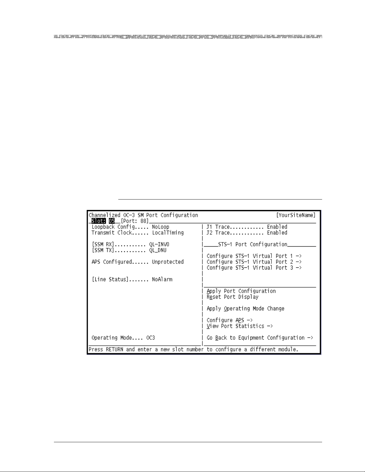
Chapter 3 Configuring the OC-3 Mode Ports and Channels Using the Console
d
Configuring All Channels on an OC-3 Port
3 After you have set all the values, select the Apply Port Configuration
command. A line status message displays:
The port and channel configuration has been applied.
See Figure 3-9. Note that two new fields are displayed:
[Working Slot].....xx , Active, (where “xx” is the even-numbered
chassis slot number where the working module is located, and
[Protection Slot]...xx , Standby
If you are configuring APS, Figure 3-9 indicates that the chassis CPU has
determine that have the correct modules in the even- and odd-numbered slots, as explained in Step 3 of the “Module Configuration Preparatory Steps” section earlier.
The active module is not ready to pass traffic in APS configuration at this
time. This occurs only after the active module is completely configured
and brought into service.
4 Remain on this window and continue with the “Accessing the Channel-
ized OC3 STS1 Port Configuration Window” procedure.
En
Figure 3-8. Channelized OC-3 Port Configuration Window (Before Configuration)
PacketStar® PSAX 1-Port Channelized OC-3/STM-1 CES Module User Guide, Issue 1 Release 11.0.0
255-700-714R11.0 3-11
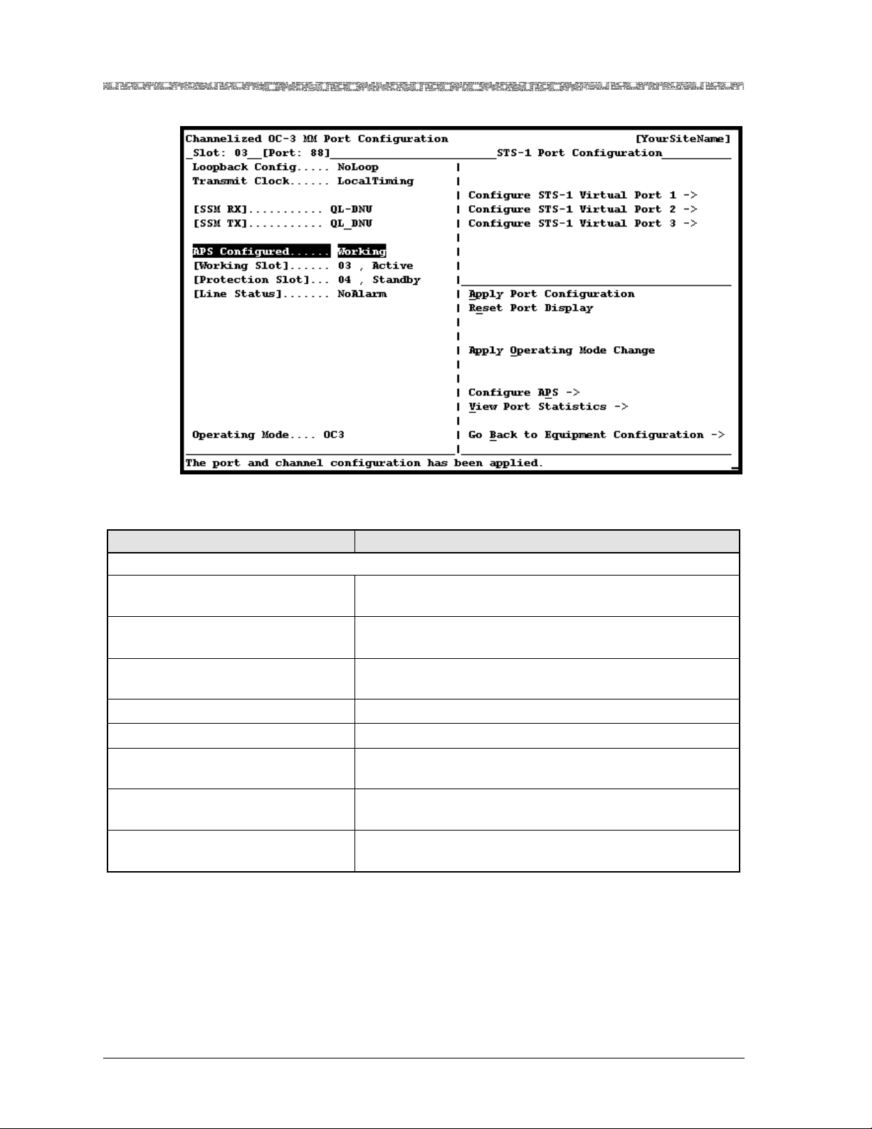
Chapter 3 Configuring the OC-3 Mode Ports and Channels Using the Console
Configuring All Channels on an OC-3 Port
Figure 3-9. Channelized OC-3 Port Configuration Window (After Configuration)
Table 3-4. Channelized OC-3 Port Configuration Window Commands
Command Function
STS-1/AU-3 Port Configuration (Right Panel)
Configure STS-1 or AU-3 Virtual
Port 1
Configure STS-1 or AU-3 Virtual
Port 2
Configure STS-1 or AU-3 Virtual
Port 3
Displays the OC-3 STS1 or the STM-1 AU-3 Port Configuration window for virtual port 1.
Displays the OC-3 STS1 or the STM-1 AU-3 Port Configuration window for virtual port 2.
Displays the OC-3 STS1 or the STM-1 AU-3 Port Configuration window for virtual port 3.
Apply Port Configuration Applies the configuration values you set on the window.
Reset Port Display Resets the fields to the last set of saved values.
Configure APS or Configure MSP Displays the Channelized OC-3 APS or STM-1 MSP Config-
uration window.
View Port Statistics Displays the Channelized OC-3 or STM-1 Port Statistics
window.
Go Back to Equipment Configu-
Redisplays the Equipment Configuration window.
ration
PacketStar® PSAX 1-Port Channelized OC-3/STM-1 CES Module User Guide, Issue 1 Release 11.0.0
3-12 255-700-714R11.0

Chapter 3 Configuring the OC-3 Mode Ports and Channels Using the Console
Configuring All Channels on an OC-3 Port
Table 3-5. Channelized OC-3 or STM-1 CES Port Configuration Window Field Descriptions
Field Name Field Value Description
Loopback Config Default: NoLoop
Range: N/A
Specifies whether and what kind of loopback configuration
is used on the signal on this connection.
Format: Predefined
NoLoop Indicates that no loopback is to be done on the signal.
LocalLoop Indicates that the received signal at this interface enters
through the backplane, is looped through the device, and
exits through the backplane.
LineLoop Indicates that received signal at this interface does not pass
through the device but is looped back out through the external port.
Transmit Clock Default: LocalTim-
ing
Range: N/A
Indicates what type of synchronization is used by the interface to maintain proper data flow through the PSAX system
and the remote devices connected to the system.
Format: Predefined
LocalTiming Selects a synchronization source (CompositeClock, T1BITS,
E1ETSI, CompositeClockDS0A, Freerun, or LineTiming) that
is provided through the Stratum 3–4 module. For GR-303
configuration, select this default.
LoopTiming This value is currently not supported.
[SSM RX] Default: QL_DNU
Range: N/A
Format: Predefined
Displays the contents of the incoming SSM bits on the port
the Stratum 3–4 module is using for line timing. The field
values represent the clock source quality level (QL) of the
SSMs.
QL-DNU
GL-INVn
GL-PRC
GL-SEC
GL-SSUL
GL-SSUT
Indicates the signal carrying this SSM shall not be used for
synchronization because a timing loop situation could result
if it is used.
Indicates an unallocated SSM value is received where n=0,
1, 3, 5, 6, 7, 9, 12, 13, or 14.
Indicates the source of the trail is a PRC clock as defined in
Recommendation ITU-T G.811.
Indicates the source of the trail is a SEC clock as defined in
Recommendation ITU-T G.813, Option I.
Indicates the source of the trail is a Type VI SSU clock as
defined in Recommendation ITU-T G.812.
Indicates the source of the trail is a Type I or V SSU clock as
defined in Recommendation ITU-T G.812.
PacketStar® PSAX 1-Port Channelized OC-3/STM-1 CES Module User Guide, Issue 1 Release 11.0.0
255-700-714R11.0 3-13

Chapter 3 Configuring the OC-3 Mode Ports and Channels Using the Console
Configuring All Channels on an OC-3 Port
Table 3-5. Channelized OC-3 or STM-1 CES Port Configuration Window Field Descriptions (Continued)
Field Name Field Value Description
[SSM TX] Default: QL_DNU
Range: N/A
Format: Predefined
Displays the contents of the SSM bits transmitted by all the
OCn/STMn module ports. The port which is active for the
purpose of stratum line timing transmits QL-DNU. All of the
other OCn/STMn modules transmit the SSM bits shown in
this field.
APS or MSP
Configured
QL-DNU
GL-INVn
GL-PRC
GL-SEC
GL-SSUL
GL-SSUT
Default: Unprotected
Range: N/A
Format: Predefined
Unprotected
Indicates the signal carrying this SSM shall not be used for
synchronization because a timing loop situation could result
if it is used.
Indicates an unallocated SSM value is received where n=0,
1, 3, 5, 6, 7, 9, 12, 13, or 14.
Indicates the source of the trail is a PRC clock as defined in
Recommendation ITU-T G.811.
Indicates the source of the trail is a SEC clock as defined in
Recommendation ITU-T G.813, Option I.
Indicates the source of the trail is a Type VI SSU clock as
defined in Recommendation ITU-T G.812.
Indicates the source of the trail is a Type I or V SSU clock as
defined in Recommendation ITU-T G.812.
Specifies whether two module(s) are to be set up in adjacent
odd- and even-numbered slots for APS/MSP protection
mode or not.
Select this value if the module is being configured as a standalone unprotected module, and
not being paired with
another module in a 1+1 protection configuration.
Working
Select this value when the module is being paired with
another identical 1+1 APS-compatible module (single-mode
or multimode with the same operating mode (see Operating
Mode field)) in a 1+1 APS configuration. Before selecting
this value, the modules must be installed as an adjacent,
consecutively numbered, pair in the PSAX chassis. To verify
the module placement, return to the Equipment Configuration window and locate the modules. The 1+1 protection
modules can only be configured when they are installed in a
consecutively numbered odd/even order, such as slots 9 and
10, 11 and 12, and so on, and not in an even/odd numbered
order, such as slots 10 and 11. In this arrangement, either
module can serve as the primary (working) module or the
standby (protection) module. After selecting this value, click
the Apply Port Configuration command. The [Working
Slot] and [Protection Slot] fields appear with the appropriate
slot numbers listed, the status of the modules, and the APS
Configuration window is available through the Configure
APS command.
PacketStar® PSAX 1-Port Channelized OC-3/STM-1 CES Module User Guide, Issue 1 Release 11.0.0
3-14 255-700-714R11.0

Chapter 3 Configuring the OC-3 Mode Ports and Channels Using the Console
Configuring All Channels on an OC-3 Port
Table 3-5. Channelized OC-3 or STM-1 CES Port Configuration Window Field Descriptions (Continued)
Field Name Field Value Description
[WorkingSlot] Default: Active
Range: N/A
Format: Predefined
Active
Displays the slot number and status of the working module
in a 1+1 APS configured module pair. This field is displayed
only when the APS Configured field is set to Workin g.
Indicates the working module is functioning properly and
the protection module is in standby.
Standby
[ProtectionSlot] Default: Standby
Range: N/A
Format: Predefined
Active
Standby
[Line Status] Default: NoAlarm
Range: N/A
Format: Predefined
Operating Mode Default: OC3
Range: N/A
Format: Predefined
Indicates the working module is in standby and the protection module is active.
Displays the slot number and status of the protection module in a 1+1 APS configured module pair. This field is displayed only when the APS Configuration field is set to
Working .
Indicates the protection module is functioning properly and
the working module is in standby.
Indicates the protection module is in standby and the working module is active.
Indicates the line status of the interface: loopback, failure,
received and transmitted alarm information. For a list of all
possible line status codes and their corresponding descriptions, see the Module Line Status Table in the Reference
Information Appendix of this guide.
Specifies the operating mode of the module. To change from
one mode to another, select this field and press Enter to display the apprpriate mode. Use the Apply Operating Mode
Change command to load the displayed operating mode.
After applying the command, approximately 25 seconds
elapse until the PSAX system recognizes the change in operating mode. After the change, it may be necessary to refresh
and display the appropriate wording on the window by toggling between this window, the previous window, and back
to this window again. When configuring the two modules
for 1+1 protection, the same operating mode must be
applied to both modules first before configuring 1+1 protection.
Note: All interfaces must be out of service, deleted, and
unconfigured before changing the operating mode.
OC3 The processing and transmission protocol is Japanese/North
American.
STM1 The processing and transmission protocol is European.
Right Panel
J1 Trace Default: Disabled
Range: N/A
Specifies whether the J1 Trace feature is enabled or disabled
for this port.
Disabled Indicates the J1 Trace feature is disabled.
Enabled Indicates the J1 Trace feature is enabled.
PacketStar® PSAX 1-Port Channelized OC-3/STM-1 CES Module User Guide, Issue 1 Release 11.0.0
255-700-714R11.0 3-15
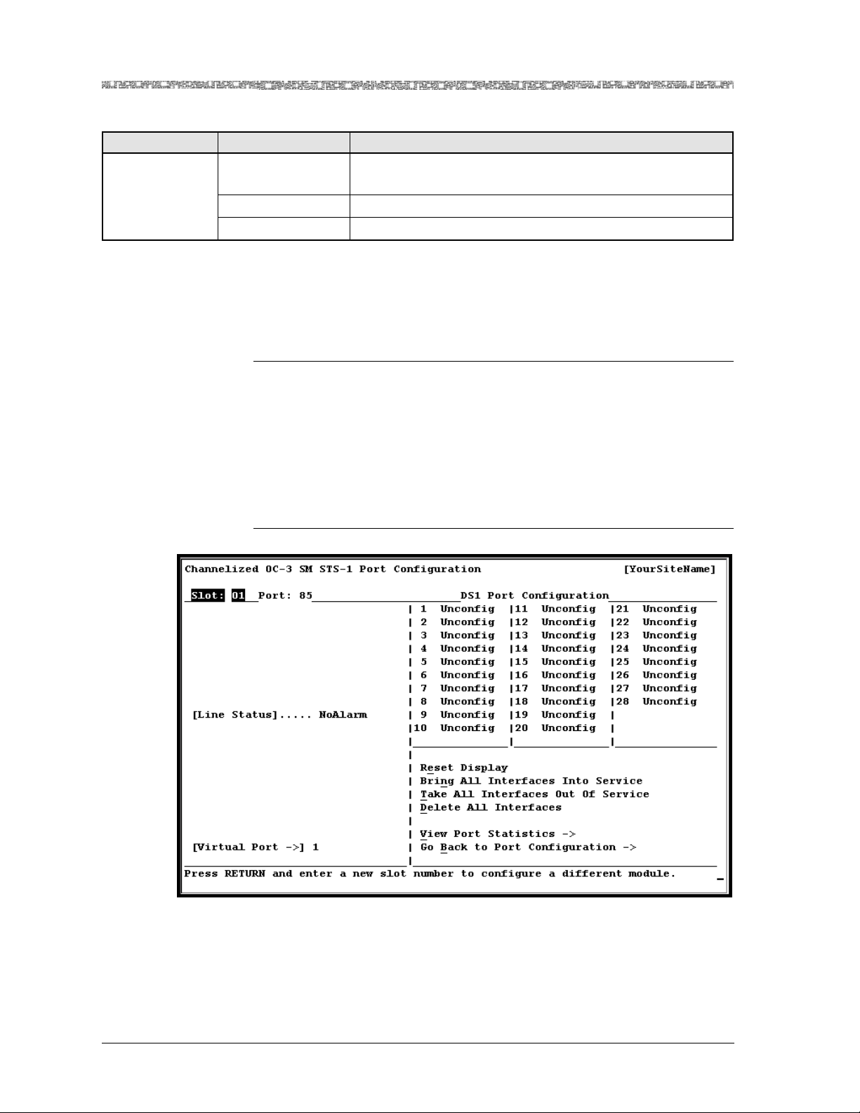
Chapter 3 Configuring the OC-3 Mode Ports and Channels Using the Console
d
Accessing the Channelized OC3 STS1 Port Configuration Window
Table 3-5. Channelized OC-3 or STM-1 CES Port Configuration Window Field Descriptions (Continued)
Field Name Field Value Description
J2 Trace Default: Disabled
Range: N/A
Specifies whether the J2 Trace feature is enabled or disabled
for this port.
Disabled Indicates the J2 Trace feature is disabled.
Enabled Indicates the J2 Trace feature is enabled.
Accessing the Channelized OC3 STS1 Port Configuration
Window
Configuring a Port with One Channel, Part 2 (Acce ssing the Channelized OC-3 STS1 Port Co nfiguration Window)
Begin
1 From the Channelized OC-3 Port Configuration window (see
Figure 3-8), select the Configure STS1 Virtual Port 1 command. The
Channelized OC-3 is displayed in Figure 3-10. Table 3-6 describes the
commands on the window. Table 3-7 describes the display only fields on
the window.
2 Remain on this window and continue with the next procedure.
En
Figure 3-10. Channelized OC-3 STS1 Port Configuration Window
PacketStar® PSAX 1-Port Channelized OC-3/STM-1 CES Module User Guide, Issue 1 Release 11.0.0
3-16 255-700-714R11.0

Chapter 3 Configuring the OC-3 Mode Ports and Channels Using the Console
Configuring All Channels on a Virtual DS1 Port on the Channelized OC-3 CES Module (No Strapping)
Table 3-6. Channelized OC-3 STS-1/STM-1 AU-3 Port Configuration Window Commands
Command Function
Reset Display Resets the fields to the last set of saved values.
Bring All Interfaces Into
Service
Brings the out-of-service, configured virtual DS1 interfaces for the
port to in-service status.
Take All Interfaces Out Of
Service
Takes the in-service configured virtual DS1 interfaces for the port to
out-of-service status. You must use this command first before using
the Delete All Interfaces command.
J1 Trace Configuration Displays the Higher Order Trace - J1 Byte Configuration window.
Delete All Interfaces Deletes the configured virtual DS1 interfaces for the port. You must
take all interfaces out of service (using the Take All Interfaces
Out Of Service command) before you can use this command to
delete all the configured interfaces.
View Port Statistics Displays the Channelized OC-3 or STM-1 Port Statistics window.
Go Back to Port Configuration
Table 3-7. Channelized OC-3/STM-1 STS-1/AU-3 Port Configuration Window Field Descriptions
Field Name Field Value Description
[Line Status] Default: NoAlarm
Range: N/A
Redisplays the 1-Port Channelized OC-3 or STM-1 Port Configuration window.
Indicates an error, if applicable. See the Reference
Information Appendix for a list of line statuses.
Format: Predefined
NoAlarm No alarm is present.
[Virtual Port –>] Default: User depen-
dent
Range: 1–3
Displays the Virtual Port selected by the user on the
right panel of the previous Channelized STM-1
SM/MM Port Configuration window.
Format: Predefined
Right Panel
E1 or DS1 Port
Configuration
Default: N/A
Range: STM-1: 1–21,
Displays the number of channels available on the
STM-1 E1 or the OC-3 DS1 port.
OC-3: 1–28
Format: Predefined
Configuring All Channels on a Virtual DS1 Port on the
Channelized OC-3 CES Module (No Strapping)
Configuring a Virtual Port with One Channel, Part 3 (Access ing the Channelized OC-3 Virtual DS1 Port Con figuration Window)
Begin
1 From the Channelized OC-3 STS1 Port Configuration window (see
Figure 3-10), select an unconfigured Virtual DS1 Port in the right panel.
The Channelized OC-3 Virtual DS1 Port Configuration window is displayed (see Figure 3-11). Table 3-8 describes the commands on this window. Table 3-9 describes the fields on the window.
PacketStar® PSAX 1-Port Channelized OC-3/STM-1 CES Module User Guide, Issue 1 Release 11.0.0
255-700-714R11.0 3-17

Chapter 3 Configuring the OC-3 Mode Ports and Channels Using the Console
d
Configuring All Channels on a Virtual DS1 Port on the Channelized OC-3 CES Module (No Strapping)
2 Select the values for the fields on this window. Since you are configuring
all the channels on the virtual DS1 port, you
must leave the default
value in the Channelization field set to its default value Disabled.
3 Select the Apply Port Configuration command. If the port configura-
tion is successful, a line status message confirms that the configuration
has been applied:
The port configuration has been applied.
4 Remain on the window and continue with the procedure “Configuring
the Channelized OC-3 Virtual DS1 Channels” on page 3-22 below.
En
Figure 3-11. Channelized OC-3 Virtual DS1 Port Configuration Window
Table 3-8. Channelized OC-3 Virtual DS1 Port Configuration Window Commands
Command Function
Show Straps Displays the Channelized OC-3 SM Virtual DS1 DS0s Strap Dis-
play window.
Apply Port Configuration For a specified virtual port number, applies the virtual port con-
figuration values you set.
Reset Display Resets the virtual port configuration fields to the last set of saved
values.
View Port Statistics Displays the Channelized OC3 STS1 Virtual Port DS1 Statistics
window.
J2 Trace Configuration Displays the Lower Order Trace - J2 Byte Configuration window.
Go to H.248 TID Configura-
Displays the Terminal ID Configuration window.
tion
PacketStar® PSAX 1-Port Channelized OC-3/STM-1 CES Module User Guide, Issue 1 Release 11.0.0
3-18 255-700-714R11.0

Chapter 3 Configuring the OC-3 Mode Ports and Channels Using the Console
Configuring All Channels on a Virtual DS1 Port on the Channelized OC-3 CES Module (No Strapping)
Table 3-8. Channelized OC-3 Virtual DS1 Port Configuration Window Commands (Continued)
Command Function
Delete All Interfaces On This
Port
Deletes the configured interfaces for all channels on the specified
virtual port. The value Unconfigured is displayed in the OperStatus field. You must first take all interfaces out of service, using
the Take All Interfaces Out Of Service command, before you
can use this command to delete all the interfaces.
Bring All Interfaces Into Service
Brings the out-of-service configured interfaces for all the channels for the specified virtual port to in-service status. The displayed asterisk is removed from all configured channels.
Take All Interfaces Out Of
Service
Takes the in-service configured interfaces for all the channels for
the specified virtual port to out-of-service status. An asterisk is
displayed beside all configured interfaces. You must use this
command first before using the Delete All Interfaces On This
Port command.
Go to Port Diagnostics Displays the DS1 Port Diagnostics window. This command works
only when the Loopback field is set to TestMode.
Go Back to Previous Window Redisplays the Channelized OC-3 SM STS-1 Port Configuration
window.
Table 3-9. Channelized OC-3 SM Virtual DS1 Port Configuration Window
Field Descriptions
Field Name Field Value Description
Line Type Default: Esf
Range: N/A
Specifies the format used in line coding transmission on
this port.
Format: Predefined
Esf Selects Extended Super Frame DS1 format.
D4 Selects D4 format.
Loopback Default: NoLoop
Range: N/A
Specifies what type of data loopback is used, if any on
this port.
Format: Predefined
NoLoop The port is not in loopback state.
LocalLoop Indicates that data is to be received from the backplane
(another module in the chassis), sent through the module circuitry, including the segmentation and reassembly
(SAR) function, and transmitted back to the backplane
(to the originating module).
LineLoop Indicates that data is to be received from the physical
port, is sent through the receiver and the line driver, and
then back out to the physical port.
PacketStar® PSAX 1-Port Channelized OC-3/STM-1 CES Module User Guide, Issue 1 Release 11.0.0
255-700-714R11.0 3-19

Chapter 3 Configuring the OC-3 Mode Ports and Channels Using the Console
Configuring All Channels on a Virtual DS1 Port on the Channelized OC-3 CES Module (No Strapping)
Table 3-9. Channelized OC-3 SM Virtual DS1 Port Configuration Window
Field Descriptions (Continued)
Field Name Field Value Description
Transmit Clock Default: LocalTim-
ing
Range: N/A
Indicates what type of synchronization is used by the
interface to maintain proper data flow through the PSAX
system and the remote devices connected to the system.
Format: Predefined
LocalTiming Selects a synchronization source (CompositeClock,
T1BITS, E1ETSI, CompositeClockDS0A, Freerun, or
LineTiming) that is provided through the Stratum 3–4
module. For GR-303 configuration, select this default.
LoopTiming Selects the recovered clock from the received data and is
used as the transmit clock on the selected interface.
[Data Tx Type]
(Data Transfer
Type)
Default: Struc-
tured
Range: N/A
Allows structured unchannelized and channelized interfaces for this port.
Format: Predefined
Channelization Default: Disabled
Specifies whether the port is channelized or not.
Range: N/A
Format: Predefined
Disabled Instructs the system not to divide the T1 line into 24
channels. Use this setting to set up only one channel for
the port. When you apply the port configuration, only
channel 1 displays the value Unconfigured.
Enabled Instructs the system to divide the T1 line into 24 chan-
nels. Use this setting to bundle (or strap together) several
DS0s into one channel and then set up one or more
channels, each having several strapped DS0s in each
channel.
Note: When you apply the port configuration, all 24
channels are displayed with the value Unconfigured.
PacketStar® PSAX 1-Port Channelized OC-3/STM-1 CES Module User Guide, Issue 1 Release 11.0.0
3-20 255-700-714R11.0

Chapter 3 Configuring the OC-3 Mode Ports and Channels Using the Console
Configuring All Channels on a Virtual DS1 Port on the Channelized OC-3 CES Module (No Strapping)
Table 3-9. Channelized OC-3 SM Virtual DS1 Port Configuration Window
Field Descriptions (Continued)
Field Name Field Value Description
UpStrm Intrworking
Default: Trunk-
Cond
Range: N/A
Format: Predefined
Specifies whether DS0 failures will affect the specific DS0
that has failed or the entire DS1 that the failed DS0 is
located in. This field allows you to select the type of
interworking to be done with the circuit emulation end
point whenever there is an alarm for the ATM side of
any CE-to-ATM connection on a given port.
TrunkCond Indicates that trunk conditioning will be done for each
channel of this port whose corresponding ATM side is
alarmed. Trunk Conditioning improves the communication of the trunk status for TDM traffic. The PSAX system
will return a busy signal only for the DS0 (each DS0 contains one time slot, i.e., one phone line) that is affected
by the connection that is not working. For more information, see the Trunk Conditioning Application Note for
PacketStar
®
PSAX Multiservice Media Gateways.
Unframed1s Indicates that unframed 1’s are to be used on the virtual
DS1. If you select this value, a sequence of Unframed All
1’s (AIS) will be transmitted to the CE end point whenever there is an alarm or the ATM side for any circuit
emulation-to-ATM connection on this port. The PSAX
system will return a busy signal for the DS1 (each DS1
contains 24 DS0s), and generate a T1 level alarm when
any of the DS0s is disconnected. The PSAX system will
also forward T1 alarms from one PBX to another. For
more information, see the Trunk Conditioning Application
®
PSAX Multiservice Media Gateways.
SG Feature Default: Disabled
Range: N/A
Note for PacketStar
Specifies whether the signaling gateway feature is
enabled or disabled for this port.
Format: Predefined
Disabled Indicates that the connection gateway feature is disabled.
Enabled
H.248 Applications and 1-Port ChOC-3/ STM-1 CES module:
The connection gateway feature is enabled. You
must use this value to use the Connection Gateway API
feature. For more information, see the PacketStar
nection Gateway API Customer Implementation Guide.
®
Con-
PacketStar® PSAX 1-Port Channelized OC-3/STM-1 CES Module User Guide, Issue 1 Release 11.0.0
255-700-714R11.0 3-21

Chapter 3 Configuring the OC-3 Mode Ports and Channels Using the Console
Configuring the Channelized OC-3 Virtual DS1 Channels
Table 3-9. Channelized OC-3 SM Virtual DS1 Port Configuration Window
Field Descriptions (Continued)
Field Name Field Value Description
CT Mode Default: Four-wire
Range: N/A
Format: Predefined
This field is currently not supported.
Continuity Test Mode:
The SG Feature field must be set
H.248 Applications,
to Enabled to use any setting in this field. The CT Mode
specifies the remote continuity test mode, where you can
select Four-Wire or Two- Wi r e. This parameter supports
the H.248 Basic Continuity Package. In a local- and
remote-end PSAX system configuration, either with
other PSAX systems or non-PSAX switches, the PSAX
can act as either the tester
*
or testee. See the “PSAX System as Tester/Testee” tables after this Field Description
Table for a summary of signal strengths that are
exchanged in the above configurations, and other pertinent information.
Four-wire This value is currently not supported. As the tester, the
PSAX applies a 2010Hz signal if the other termination is
4-wire. As the testee, the PSAX acts in loopback mode if
the other termination is 4-wire.
Two- wi re This value is currently not supported. As the tester, the
PSAX applies a 1780Hz signal if the other termination is
2-wire. As the testee, the PSAX acts in transponder mode
if the other termination is 2-wire.
[Line Status] Default: NoAlarm
Range: N/A
Format: Predefined
*
The PSAX System side of a local/remote configuration can function as the tester or the testee in configuration with another PSAX, a non-PSAX switch, and a media gateway controller (MGC). Regardless of
tester or testee status, the PSAX system side is always 4-wire. When interfacing with a 2-wire device, the
PSAX converts its 4-wire signal (2010-Hz) to a 2-wire (1780-Hz) signal when replying to a 2-wire device,
thus operating in transponder mode. As the testee, the PSAX system can act in loopback mode if the
remote end is 4-wire. The loopback mode is configured on the Media Gateway Controller configured with
the PSAX system. The signaling call progress tones (dial, ringing, busy, congestion, special information,
caller waiting) are generated from the TAS module in CAS mode in configuration with the MGC. All
other signals, such as continuity check and the 10x tests (102, 105, and 108) are generated from the TAS
module in TAS mode. See the Tones and Announcements Server Module User Guide for more information.
Specifies a line status failure or constraint if applicable.
See the reference information appendix in this user
guide.
Configuring the Channelized OC-3 Virtual DS1 Channels
Perform the following procedure to configure the virtual DS1 channels.
Begin
1 On the Channelized OC-3 Virtual DS1 Port Configuration window (see
Figure 3-11), select the unconfigured channel 1 on the right panel of the
window. The Channelized OC-3 Virtual DS1 Channel Configuration win-
PacketStar® PSAX 1-Port Channelized OC-3/STM-1 CES Module User Guide, Issue 1 Release 11.0.0
3-22 255-700-714R11.0

Chapter 3 Configuring the OC-3 Mode Ports and Channels Using the Console
d
Configuring the Channelized OC-3 Virtual DS1 Channels
dow is displayed (see Figure 3-12). Table 3-10 describes the commands
on the window. Table 3-11 describes the configurable fields on the window.
Note: You must have selected the value Disabled in the Channelization
field on the module’s Port and Channel Configuration window (see
Figure 3-11).
2 In the Interface Type field on Table 3-11, select one of the following
interface types available.
If you select CircuitEmulation as the interface type, the Signaling field
displays. In the Signaling field, select either Disabled (default) or
Enabled, and press Enter.
3 Select the Apply Configuration command.
4 Select the Configure Interface command.
One of the following interface configuration windows displays:
~ Circuit Emulation Interface Configuration window.
~ GR303 Interface and DS0 Configuration window
5 Proceed to Chapter 5 in this User Guide for instructions on configuring
your chosen interface type.
6 Repeat Steps 1–5 under “Configuring the Channelized OC-3 Virtual DS1
Channels” on page 3-22, and steps 1–4 in this procedure for the remainder of the ports, as needed.
Note: Be sure to complete the module port and channel configuration
and then the interface configuration for each port before beginning
the configuration of a new port.
En
PacketStar® PSAX 1-Port Channelized OC-3/STM-1 CES Module User Guide, Issue 1 Release 11.0.0
255-700-714R11.0 3-23

Chapter 3 Configuring the OC-3 Mode Ports and Channels Using the Console
Configuring the Channelized OC-3 Virtual DS1 Channels
Figure 3-12. Channelized OC-3 Virtual DS1 Channel Configuration Window for
Channelization Disabled Default
Table 3-10. Channelized OC-3/STM-1 Virtual DS1/E1 Channel Configuration Window Commands
Command Function
Apply Configuration Applies the interface configuration you selected for a specified
port and channel number value.
Reset Display Resets the fields to the last set of saved values.
Bring Interface Into Service Brings the out-of-service configured interface to in-service sta-
tus. The value InService is displayed in the [Operational Status] and the [Administrative Status] fields.
Take Interface Out Of Service Takes the in-service configured interface to out-of-service sta-
tus. The value OutOfService is displayed in the Operational
Status and the Administrative Status fields.
Configure Interface Displays an interface configuration window for the selected
port.
Go Back to Port Configuration Redisplays the Channelized STS1 Virtual Port Configuration
window.
PacketStar® PSAX 1-Port Channelized OC-3/STM-1 CES Module User Guide, Issue 1 Release 11.0.0
3-24 255-700-714R11.0

Chapter 3 Configuring the OC-3 Mode Ports and Channels Using the Console
Configuring the Channelized OC-3 Virtual DS1 Channels
Table 3-11. Channelized OC-3/STM-1 Virtual DS1/E1 Channel Configuration Window
Field Descriptions
Field Name Field Value Description
[Slot: nn] Default: selected
slot
Indicates the PSAX chassis slot that the selected module occupies.
Range: 1-16
Format: Numeric
Port: nn Default: Va ri able
Range: 1–3
Indicates one of three ports selected; 1, 2, or 3. Each port offers
28 virtual channels.
Format: Numeric
Channel: 00n Default: Var i a b l e
Range: 1-24
Format: Numeric
Interface Type Default: Uncon-
figured
Indicates the channel selected. Only channel 001 is available
when the Channelization field is disabled on the Channelized
OC-3/STM-1 Virtual DS1 Port Configuration window.
Specifies which end-to-end interface protocol the connection
will operate under.
Range: N/A
Format: Predefined
Unconfigured This interface is not configured.
Circuit Emulation
64 Kbps DS0 connection.
Note: When this type is selected, the Signaling field below the
Interface Type field is display only and not configurable.
Gr303 Telcordia General Requirement 303 standard for LES. The Sig-
naling field does not display for this value.
Pri-isdn-user The PSAX system will provide full support for this interface
over the H.248 protocol in a future release. Primary Rate Interface ISDN for the user side.
Note: When this type is selected, the Signaling field below the
Interface Type field displays with the default Disabled. The
Signaling field is configurable as Enabled or Disabled.
Pri-isdn-network
The PSAX system will provide full support for this interface
over the H.248 protocol in a future release. Primary Rate Interface ISDN for the network side.
Note: When this type is selected, the Signaling field below the
Interface Type field displays with the default Disabled. The
Signaling field is configurable as Enabled or Disabled.
CasTrunkLine This interface is currently not supported.
[Signaling] or
Signaling
Default: Disabled
Range: N/A
Signaling is always separate from the bearer channel in CE and
ISDN.
Format: Predefined
Disabled Disables signaling. If configuring the interface as IDSN without
a signaling gateway, you must select Disabled for this field and
configure the module interface as CES.
Enabled Enables signaling.
PacketStar® PSAX 1-Port Channelized OC-3/STM-1 CES Module User Guide, Issue 1 Release 11.0.0
255-700-714R11.0 3-25

Chapter 3 Configuring the OC-3 Mode Ports and Channels Using the Console
Configuring One or More Channels On A Port (Strapping)
Table 3-11. Channelized OC-3/STM-1 Virtual DS1/E1 Channel Configuration Window
Field Descriptions (Continued)
Field Name Field Value Description
[Admin Status] Unconfigured
Range: N/A
The interface is not administratively in service because it is not
configured.
Format: Predefined
Unconfigured The interface is not configured to pass traffic.
InService Indicates that no conditions are preventing the port from being
fully operational.
OutOfService Indicates that some condition is preventing the port from being
configured with an interface
[Oper Status] Default: Uncon-
Specifies whether the interface is operational or not.
figured
Range: N/A
Format: Predefined
Unconfigured The interface is not configured to pass traffic.
InService The configured interface is currently operational (that is, capa-
ble of receiving and sending signals).
OutOfService The configured interface is not currently operational (that is,
not capable of receiving and sending signals).
[Available
DS0s]:
[DS0s
Strapped]
Default: N/A
Range: 1–24
Format: Numeric
Default: N/A
Range: 1–24
Format: Numeric
Indicates the number of DS0s available to be strapped to a particular channel. DS0s are only available when channelization is
Enabled.
Indicates the number of DS0s strapped to a particular channel.
When channelization is disabled, all 24 DS0s are strapped to
channel 001.
Configuring One or More Channels On A Port (Strapping)
Configuring a Port with Several Channels, Part 1 ( Accessing the Ch OC-3 Virtual DS1 Port Configura tion Window)
Begin
1 From the previous Channelized OC-3 STS1 Port Configuration window
(see Figure 3-10), select an Unconfigured Virtual DS1 Port and press
Enter. The Channelized OC-3 Virtual DS1 Port Configuration window is
displayed. Table 3-8 describes the commands on the window. Table 3-9
describes the configurable fields on the window.
2 Select the values for the fields on this window from Table 3-9. In the
Channelization field, you
value Enabled.
3 Select the Apply Port Configuration command. As soon as the config-
uration is applied, you will see 24 unconfigured channels on the right
panel. A line status message should confirm the configuration is applied:
PacketStar® PSAX 1-Port Channelized OC-3/STM-1 CES Module User Guide, Issue 1 Release 11.0.0
3-26 255-700-714R11.0
must change the default value on the default

Chapter 3 Configuring the OC-3 Mode Ports and Channels Using the Console
d
Configuring a Port with One or More Channels, (Accessing the Channelized OC-3 Virtual DS1 Channel Configuration
The port configuration has been applied.
4 Remain on this window and continue with the next procedure, “Config-
uring a Port with One or More Channels, (Accessing the Channelized
OC-3 Virtual DS1 Channel Configuration Window) (Strapping)”.
En
Configuring a Port with One or More Channels, (Accessing the Channelized OC-3 Virtual DS1 Channel Configuration Window) (Strapping)
Configuring a Port with Several Channels, Part 2, (Accessing the Channe lized OC-3 Virtual DS1 Channel Configuration Window)
Begin
1 On the Channelized OC-3 STS1 Port Configuration window (see
Figure 3-10), select an unconfigured channel on the right panel of the
window. The Channelized OC-3 Virtual DS1 Channel Configuration window is displayed (see Figure 3-11). Table 3-8 describes the commands on
the window. Table 3-9 describes the configurable fields on the window.
Note: You must have selected the value Enabled in the Channelization
field on the Channelized OC-3 Virtual DS1 Port Configuration window (see Figure 3-11).
2 In the Interface Type field, select one of the following types of interface
types from Table 3-9.
If you select CircuitEmulation as the interface type, the Signaling field
displays. If you want to strap any channels together, do not change the
Signaling field default, which is Disabled.
3 Begin the strapping process by using the arrow key to highlight an Avail-
able DS0 that you want to strap with other DS0s in the [Available DS0s]
field.
4 Press Enter. This action displays an X below DS0 number. Repeat steps 3
and 4 until you have strapped all the DS0s you want to strap for the
selected channel. (In the sample configuration shown in Figure 3-13,
channels 1 through 5 have been strapped).
5 Select the Apply Configuration command and press Enter.
In the [DS0s Strapped] field (display only), the values for the DS0s you
just selected are displayed (see Figure 3-14). This first group of strapped
DS0s are now shown as Channel 1 on the Ch OC-3 Virtual DS1 Channel
Configuration window.
6 To strap together more DS0s for another channel in the selected port,
reselect the Channel field and enter the next channel number you want
to strap.
7 Repeat step 2-6 for the rest of the available DS0s (or as many as you
want to use).
PacketStar® PSAX 1-Port Channelized OC-3/STM-1 CES Module User Guide, Issue 1 Release 11.0.0
255-700-714R11.0 3-27

Chapter 3 Configuring the OC-3 Mode Ports and Channels Using the Console
d
Configuring a Port with One or More Channels, (Accessing the Channelized OC-3 Virtual DS1 Channel Configuration
8 To view the strapped DS0s and their associated channels at any time,
select the Show Straps command on the Ch OC-3 Virtual DS1 Port
Configuration window (see Figure 3-14).
En
Figure 3-13. Strapped Channels 1 Through 5 Displaying After Apply
Configuration Command Has Been Applied
Figure 3-14. Displays Strapping on the Channelized OC-3 Virtual DS1 DS0s Strap
Display Window
PacketStar® PSAX 1-Port Channelized OC-3/STM-1 CES Module User Guide, Issue 1 Release 11.0.0
3-28 255-700-714R11.0

Chapter 3 Configuring the OC-3 Mode Ports and Channels Using the Console
Configuring the OC-3 Working and Standby Module Pair
Table 3-12. Channelized OC-3/STM-1 Virtual DS1/E1 DS0s Strap Display Window Commands
Command Function
Update Display Updates the display of strapped DS0 channels.
Go Back to DS1 or E1 Port Configuration
Redisplays the Channelized OC-3 SM Virtual DS1 Port Configuration or Channelized STM-1 SM Virtual E1 Port and Channel Configuration window.
Table 3-13. Channelized OC-3/STM-1 Virtual DS1/E1 DS0s Strap Display Window
Field Descriptions
Field Name Field Value Description
[Slot: ] Default: selected
slot
Specifies the slot where the module resides with
virtual strapped DS0s.
Range: Variable
Format: Numeric
Port: Default: User-
assigned
Enter the number of the virtual port for which
you want to view the strapped DS0s.
Range: DS1: 1–24 or
E1: 1–31
Format: Numeric
Ch DS0s
(display only)
Default: N/A
Range: DS1: 1–24 or
The strapped DS0s are grouped into channels.
E1: 1–31
Format: Numeric
Configuring the OC-3 Working and Standby Module Pair
Note: Make sure that you have selected and applied the APS Configured
setting of working to the correct module as shown in Figure 3-15
before starting APS configuration. This window was displayed after
the Apply Port Configuration command in the “Configuring All
Channels on an OC-3 Port” on page 3-10 procedure earlier in this
chapter (if the modules are not in the correct slots, your window
will not look like Figure 3-15).
Begin
1 From the Channelized OC-3 Port Configuration window (see
Figure 3-15), select the Configure APS command. The Channelized
OC-3 APS Configuration window is displayed (see Figure 3-16).
Table 3-14 describes the commands for this window. Table 3-15 describes
the configurable fields on the right panel and the display only statistics
fields on the left panel.
2 Select the values for the fields on the window in Figure 3-15 from
Table 3-15.
PacketStar® PSAX 1-Port Channelized OC-3/STM-1 CES Module User Guide, Issue 1 Release 11.0.0
255-700-714R11.0 3-29

Chapter 3 Configuring the OC-3 Mode Ports and Channels Using the Console
d
Configuring the OC-3 Working and Standby Module Pair
3 After selecting the field options you want, select the Apply Port Con-
figuration command (see Figure 3-16).
The port and channel configuration has been applied.
If you have completed the configuration of the primary working module,
the module pair is now configured for MSP protection and the working
module is ready to pass traffic.
After you configured the first Channelized STM-1 ATM MM/SM MSP
module, in an even- or odd-numbered slot, it is designated the “working” module and is now functioning in active status. The module in the
adjacent slot is designated the “standby protection” module and is now
functioning in standby status. As the signal is received in the working
(active) module, it is also being sent to the protection (standby) module,
which drops the signal because is it not needed. If the working module in
active status fails, the system puts the protection module into active status, and the working module into standby status. At a later time when
the working module is replaced or otherwise made operational, the
active status cannot revert automatically to the working module. To
cause the active status to revert to the working module, you must apply a
command on the Channelized STM-1 ATM MM/SM MSP Configuration
window (see Figure 3-16 and Table 3-14).
With the conclusion of this procedure, your module pair(s) are ready to
pass traffic.
4 If you have finished all configuration on the active module, you should
save the configuration by completing “Saving the Equipment Configuration and Logging Off”, the next procedure.
This chapter concludes with the procedures for viewing the connection
statistics, which are after the “Saving the Equipment Configuration and
Logging Off” procedure.
En
PacketStar® PSAX 1-Port Channelized OC-3/STM-1 CES Module User Guide, Issue 1 Release 11.0.0
3-30 255-700-714R11.0

Chapter 3 Configuring the OC-3 Mode Ports and Channels Using the Console
Configuring the OC-3 Working and Standby Module Pair
Figure 3-15. Module Configured for 1+1 Protection (Working Module)
Figure 3-16. Channelized OC-3 APS Configuration Window
Table 3-14. Channelized OC-3STM-1 APS/MSP Configuration Window Commands
Command Function
APS/MSP Statistics (Left Panel)
Continuous Update Updates the values in the fields every second.
Reset APS/MSP Statistics Sets all field values to 0.
PacketStar® PSAX 1-Port Channelized OC-3/STM-1 CES Module User Guide, Issue 1 Release 11.0.0
255-700-714R11.0 3-31

Chapter 3 Configuring the OC-3 Mode Ports and Channels Using the Console
Configuring the OC-3 Working and Standby Module Pair
Table 3-14. Channelized OC-3STM-1 APS/MSP Configuration Window Commands (Continued)
Command Function
APS/MSP Commands (Left Panel)
Apply APS/MSP Command Runs the command you selected in the APS Command or
MSP Command field.
Configuration Commands (Right Panel)
Apply APS/MSP Parameters Applies the configuration values for both the primary and the
standby OC-3c APS or MSP modules.
Reset APS/MSP Display Resets the fields to the last set of saved values.
Go Back to Port Configura-
Redisplays the Port and Channel Configuration window.
tion
Table 3-15. Channelized OC-3 MM APS Configuration Window Field Descriptions
Field Name Field Value Description
APS Statistics Panel (display only)
Working Port SF
Dur
Default: 00000000
Range: 0–99999999
Format: Numeric
(seconds)
Working Port SD
Dur
Default: 00000000
Range: 0–99999999
Format: Numeric
(seconds)
Prot. Port SF Duration
Default: 00000000
Range: 0–99999999
Format: Numeric
(seconds)
Prot. Port SD Duration
Default: 00000000
Range: 0–99999999
Format: Numeric
(seconds)
Switch Over Counts Default: 00000
Range: 0–99999
Format: Numeric
Displays the amount of time in seconds that the working port has had a failed signal (SF) above the selected
threshold bit error rate. This value changes dynamically for the life of the connection.
The amount of time in seconds that the working port
has had a degraded signal (SD) above the selected
threshold bit error rate. This value changes dynamically for the life of the connection.
The amount of time in seconds that the protection port
has had a failed signal (SF) above the selected threshold bit error rate. This value changes dynamically for
the life of the connection.
The amount of time in seconds that the protection port
has had a degraded signal (SD) above the selected
threshold bit error rate. This value changes dynamically for the life of the connection.
The number of times that switchover of active status
from one module to the other in the pair has occurred.
This is an incrementing value displayed as an integer.
(integer)
TX K1/K2
*
Default: 00/00
Range: 99/99
Format: Hexadecimal
bytes
For the transmit port, the protocol for the APS channel, carried in the K1 and K2 bytes, in the signal in the
protection line. The K1 byte is used to indicate a
request by a channel for a switch action. The K2 byte is
used to indicate the bridging actions performed at the
LTE, and the provisioned architecture and mode of
operation
PacketStar® PSAX 1-Port Channelized OC-3/STM-1 CES Module User Guide, Issue 1 Release 11.0.0
3-32 255-700-714R11.0

Chapter 3 Configuring the OC-3 Mode Ports and Channels Using the Console
Configuring the OC-3 Working and Standby Module Pair
Table 3-15. Channelized OC-3 MM APS Configuration Window Field Descriptions (Continued)
Field Name Field Value Description
RX K1/K2
*
Default: 00/00
Range: 99/99
Format: Hexadecimal
For the receive port, the protocol for the APS channel,
carried in the K1 and K2 bytes, in the signal in the protection line. See the description in the preceding row.
bytes
APS Commands Panel
Note: Use the commands in this panel as needed to manage the primary and standby modules in
adjacent slots.
[Cur. St.] Default: NoRequest,
Localprotect-
Indicates which command listed for the APS Command field below are currently applied.
DoNotRevert
APS Command Default: NoAction
Range: N/A
Format: Predefined
Allows the system software to perform switchover of
active status between the module pair automatically, as
needed.
Typically, the following APS switch-over commands
are used for testing and maintenance activities.
ManualSwitchToWorkPort
ManualSwitchToProtPort
ForcedSwitchToWorkPort
ForcedSwitchToProtPort
Switches the active status from the protection module
to the working module (lowest priority command).
Switches the active status from the working module to
the protection module (lowest priority command).
Switches the active status from the protection module
to the working module (higher priority command).
Switches the active status from the working module to
the protection module (higher priority command).
LockoutProtection Regardless of whether the working module has failed,
prevents the switchover of active status from the working module to the active module.
Clear Clears the currently applied command. Use this com-
mand to clear an existing command (other than NoAc-
tion) before applying another switchover command.
Configuration Parameters/Status Panel
APS Mode Default: Unidirec-
tional
Range: N/A
Format: Predefined
Specifies whether traffic flow is one-way or two-way.
Prior to entering bidirectional mode from unidirectional mode, you should clear outstanding manual
commands and line status. Otherwise you may have to
manually synchronize the two nodes.
Unidirectional APS switchover is governed by conditions on which-
ever end of the termination is set to unidirectional in
the send direction.
Bidirectional APS switchover is governed by both near-end and far-
end conditions. The active (or non-standby) port of the
termination must remain in synchronization with the
far-end active (or non-standby) port for successful
switchover to occur.
PacketStar® PSAX 1-Port Channelized OC-3/STM-1 CES Module User Guide, Issue 1 Release 11.0.0
255-700-714R11.0 3-33

Chapter 3 Configuring the OC-3 Mode Ports and Channels Using the Console
Configuring the OC-3 Working and Standby Module Pair
Table 3-15. Channelized OC-3 MM APS Configuration Window Field Descriptions (Continued)
Field Name Field Value Description
[APS Option] Default: Nonrever-
tive
Range: N/A
Format: Predefined
Working SF BER Default: TenToMinu
s4
Range: N/A
Format: Predefined
TenToMinus4
Indicates that once the active status has switched from
the working module to the protection module, the
active status cannot revert automatically to the working module.
Specifies the signal-failure bit error rate (SF BER)
threshold on the working module port. When the BER
exceeds the threshold, the system switches the active
status from the working module to the protection
module.
Selects an SF BER of 10
-4
for an extremely low quality
signal threshold.
TenToMinus5
Selects an SF BER of 10
-5
for a very low quality signal
threshold, which indicates a signal failure (SF).
Working SD BER Default: Default:
TenToMinus5
Range: N/A
Format: Predefined
TenToMinus5 10
TenToMinus6 10
TenToMinus7 10
TenToMinus8 10
Protection SF BER Default: TenToMinu
s4
-4
Range: 10
– 10
-5
Format: Predefined
TenToMinus4 10
TenToMinus5 10
Protection SD BER Default: TenToMinu
s5
Range: N/A
Format: Predefined
TenToMinus5 10
TenToMinus6 10
TenToMinus7 10
TenToMinus8 10
Specifies the signal-degraded bit error rate (SD BER)
value on the working module port.
-5
(lowest quality threshold, indicates that the signal
is “signal degraded” (SD).
-6
(lower than 10-7 quality threshold).
-7
(lower than 10-8 quality threshold).
-8
(low quality).
Specifies the signal-failure bit error rate (SF BER) for
the protection module port. When the BER value on
the protection port exceeds the threshold value, the
system switches the active status from the protection
module to the working module.
-4
(extremely low quality signal).
-5
(very low quality signal, indicates a failed signal
(SF)).
Specifies the signal-degraded bit error rate (SD BER)
value on the APS protection module port.
5
(lowest quality threshold, indicates a “signal
degraded” (SD) status).
6,
(lower than 10-7 quality threshold).
5
, (lower than 10-8 quality threshold).
-8
(low quality).
PacketStar® PSAX 1-Port Channelized OC-3/STM-1 CES Module User Guide, Issue 1 Release 11.0.0
3-34 255-700-714R11.0

Chapter 3 Configuring the OC-3 Mode Ports and Channels Using the Console
Configuring J1 Trace
Table 3-15. Channelized OC-3 MM APS Configuration Window Field Descriptions (Continued)
Field Name Field Value Description
[Working Line] Default: NoAlarm
Indicates the status of the port on the working module.
Range: N/A
Format: Predefined
NoAlarm No alarms exist on the working module.
ModuleFailure The working module has failed.
[Protection Line] Default: NoAlarm
Range: N/A
Indicates the status of the port on the protection module.
Format: Predefined
NoAlarm No alarms exist on the protection module.
ModuleFailure The protection module has failed.
[APS Status] Default: NoFailure
Range: N/A
Indicates whether a switchover has occurred from one
module to the other module in the pair.
Format: Predefined
*
For the STM-1 MSP and STM-4 MSP modules, the ITU-T G.841 Transmission Systems and Media, Digital
Systems and Networks, Section 7.1 (formerly G.783 Annex A) mandates channel 0 to indicate the switch
configuration and channel 1 to indicate the bridge configuration. The PSAX system is compliant with
G.841 Section 7.1 by using channel 0 and 1 coding in both the uni- and bi-directional modes. For the OC3c APS and OC-12c APS modules, the Telcordia GR-253-CORE Synchronous Optical Network (SONET)
Transport Systems: Common Generic Criteria (formerly G.783 Annex B) mandates channel 1 to indicate
the switch configuration and channel 2 to indicate the bridge configuration (0 indicates no request). The
PSAX is not compliant with G.841 Annex B. The APS and MSP protocol are using the K1/K2 byte in the
SONET/SDH overhead to exchange information between multiplexed section endpoints. The protocols
are using bit 6 to 8 of the K2 byte in a different way: The STM-1 MSP and STM-4 MSP modules are using
these bits from the K2 byte to indicate an MS-AIS or MS-RDI alarm. The OC-3 APS and OC-12 APS module are using these bits from the K2 byte to indicate the mode of operation. On the Msp-STM-1SM MSP
Configuration menu, the PSAX system menu displays the K1/K2 byte values it is transmitting and/or
receiving, but those values do not include the values for the K2 bits 6-8. For interworking between a CBX
500® system and a PSAX system, the CBX and the PSAX use different state machines for bi-directional
transmission, causing the MSP function to lock up. In links from the PSAX to the CBX, the state machines
are compatible for unidirectional links.
Configuring J1 Trace
The J1 and J2 byte configuration ensures that data reaches the correct destination and also helps in long term data monitoring.
Perform the following procedure to configure the J1 Trace on the Channelized OC-3 SM STS1 Port Configuration window.
Begin
1 From the OC-3 SM Port Configuration window (see Figure 3-8), set the
J1 Trace field to Enabled (see Table 3-16).
Note: From the Channelized OC-3 SM Port Configuration window,
verify that the J1 Trace field is set to Enabled.
PacketStar® PSAX 1-Port Channelized OC-3/STM-1 CES Module User Guide, Issue 1 Release 11.0.0
255-700-714R11.0 3-35

Chapter 3 Configuring the OC-3 Mode Ports and Channels Using the Console
d
Configuring J1 Trace
2 After applying the Port Configuration command in the OC-3 SM Port
Configuration window (see Figure 3-8), select the Configure STS1 Vir-
tual Port 1.
The Channelized OC-3 SM STS1 Port Configuration window is displayed
(see Figure 3-17). Table 3-6 describes the commands on the window.
Table 3-7 describes the fields on the window.
3 Remain on the same window, select the J1 Trace Configuration com-
mand.
The Higher Order Path Trace - J1 Byte Configuration window is displayed (see Figure 3-18). Table 3-17 describes the commands on this
window. Table 3-18 describes the configurable fields on this window.
4 Select the values for the fields on the window in Figure 3-18 from
Table 3- 1 8 .
5 Select the Apply Configuration command and press Enter.
En
Table 3-16. Channelized OC-3 or STM-1 CES Port Configuration Window Field Descriptions
Field Name Field Value Description
Loopback Config Default: NoLoop
Range: N/A
Specifies whether and what kind of loopback configuration
is used on the signal on this connection.
Format: Predefined
NoLoop Indicates that no loopback is to be done on the signal.
LocalLoop Indicates that the received signal at this interface enters
through the backplane, is looped through the device, and
exits through the backplane.
LineLoop Indicates that received signal at this interface does not pass
through the device but is looped back out through the external port.
Transmit Clock Default: LocalTim-
ing
Range: N/A
Indicates what type of synchronization is used by the interface to maintain proper data flow through the PSAX system
and the remote devices connected to the system.
Format: Predefined
LocalTiming Selects a synchronization source (CompositeClock, T1BITS,
E1ETSI, CompositeClockDS0A, Freerun, or LineTiming) that
is provided through the Stratum 3–4 module. For GR-303
configuration, select this default.
LoopTiming This value is currently not supported.
PacketStar® PSAX 1-Port Channelized OC-3/STM-1 CES Module User Guide, Issue 1 Release 11.0.0
3-36 255-700-714R11.0

Chapter 3 Configuring the OC-3 Mode Ports and Channels Using the Console
Configuring J1 Trace
Table 3-16. Channelized OC-3 or STM-1 CES Port Configuration Window Field Descriptions (Continued)
Field Name Field Value Description
[SSM RX] Default: QL_DNU
Range: N/A
Format: Predefined
Displays the contents of the incoming SSM bits on the port
the Stratum 3–4 module is using for line timing. The field
values represent the clock source quality level (QL) of the
SSMs.
QL-DNU
GL-INVn
GL-PRC
GL-SEC
GL-SSUL
GL-SSUT
[SSM TX] Default: QL_DNU
Range: N/A
Format: Predefined
QL-DNU
Indicates the signal carrying this SSM shall not be used for
synchronization because a timing loop situation could result
if it is used.
Indicates an unallocated SSM value is received where n=0,
1, 3, 5, 6, 7, 9, 12, 13, or 14.
Indicates the source of the trail is a PRC clock as defined in
Recommendation ITU-T G.811.
Indicates the source of the trail is a SEC clock as defined in
Recommendation ITU-T G.813, Option I.
Indicates the source of the trail is a Type VI SSU clock as
defined in Recommendation ITU-T G.812.
Indicates the source of the trail is a Type I or V SSU clock as
defined in Recommendation ITU-T G.812.
Displays the contents of the SSM bits transmitted by all the
OCn/STMn module ports. The port which is active for the
purpose of stratum line timing transmits QL-DNU. All of the
other OCn/STMn modules transmit the SSM bits shown in
this field.
Indicates the signal carrying this SSM shall not be used for
synchronization because a timing loop situation could result
if it is used.
GL-INVn
Indicates an unallocated SSM value is received where n=0,
1, 3, 5, 6, 7, 9, 12, 13, or 14.
GL-PRC
Indicates the source of the trail is a PRC clock as defined in
Recommendation ITU-T G.811.
GL-SEC
Indicates the source of the trail is a SEC clock as defined in
Recommendation ITU-T G.813, Option I.
GL-SSUL
Indicates the source of the trail is a Type VI SSU clock as
defined in Recommendation ITU-T G.812.
GL-SSUT
Indicates the source of the trail is a Type I or V SSU clock as
defined in Recommendation ITU-T G.812.
PacketStar® PSAX 1-Port Channelized OC-3/STM-1 CES Module User Guide, Issue 1 Release 11.0.0
255-700-714R11.0 3-37

Chapter 3 Configuring the OC-3 Mode Ports and Channels Using the Console
Configuring J1 Trace
Table 3-16. Channelized OC-3 or STM-1 CES Port Configuration Window Field Descriptions (Continued)
Field Name Field Value Description
APS or MSP
Configured
Default: Unpro-
tected
Range: N/A
Specifies whether two module(s) are to be set up in adjacent
odd- and even-numbered slots for APS/MSP protection
mode or not.
Format: Predefined
Unprotected
Select this value if the module is being configured as a standalone unprotected module, and
not being paired with
another module in a 1+1 protection configuration.
Working
[WorkingSlot] Default: Active
Range: N/A
Format: Predefined
Active
Select this value when the module is being paired with
another identical 1+1 APS-compatible module (single-mode
or multimode with the same operating mode (see Operating
Mode field)) in a 1+1 APS configuration. Before selecting
this value, the modules must be installed as an adjacent,
consecutively numbered, pair in the PSAX chassis. To verify
the module placement, return to the Equipment Configuration window and locate the modules. The 1+1 protection
modules can only be configured when they are installed in a
consecutively numbered odd/even order, such as slots 9 and
10, 11 and 12, and so on, and not in an even/odd numbered
order, such as slots 10 and 11. In this arrangement, either
module can serve as the primary (working) module or the
standby (protection) module. After selecting this value, click
the Apply Port Configuration command. The [Working
Slot] and [Protection Slot] fields appear with the appropriate
slot numbers listed, the status of the modules, and the APS
Configuration window is available through the Configure
APS command.
Displays the slot number and status of the working module
in a 1+1 APS configured module pair. This field is displayed
only when the APS Configured field is set to Working.
Indicates the working module is functioning properly and
the protection module is in standby.
Standby
Indicates the working module is in standby and the protection module is active.
[ProtectionSlot] Default: Standby
Range: N/A
Format: Predefined
Active
Displays the slot number and status of the protection module in a 1+1 APS configured module pair. This field is displayed only when the APS Configuration field is set to
Working .
Indicates the protection module is functioning properly and
the working module is in standby.
Standby
Indicates the protection module is in standby and the working module is active.
PacketStar® PSAX 1-Port Channelized OC-3/STM-1 CES Module User Guide, Issue 1 Release 11.0.0
3-38 255-700-714R11.0

Chapter 3 Configuring the OC-3 Mode Ports and Channels Using the Console
Configuring J1 Trace
Table 3-16. Channelized OC-3 or STM-1 CES Port Configuration Window Field Descriptions (Continued)
Field Name Field Value Description
[Line Status] Default: NoAlarm
Range: N/A
Format: Predefined
Indicates the line status of the interface: loopback, failure,
received and transmitted alarm information. For a list of all
possible line status codes and their corresponding descriptions, see the Module Line Status Table in the Reference
Information Appendix of this guide.
Operating Mode Default: OC3
Range: N/A
Format: Predefined
Specifies the operating mode of the module. To change from
one mode to another, select this field and press Enter to display the apprpriate mode. Use the Apply Operating Mode
Change command to load the displayed operating mode.
After applying the command, approximately 25 seconds
elapse until the PSAX system recognizes the change in operating mode. After the change, it may be necessary to refresh
and display the appropriate wording on the window by toggling between this window, the previous window, and back
to this window again. When configuring the two modules
for 1+1 protection, the same operating mode must be
applied to both modules first before configuring 1+1 protection.
Note: All interfaces must be out of service, deleted, and
unconfigured before changing the operating mode.
OC3 The processing and transmission protocol is Japanese/North
STM1 The processing and transmission protocol is European.
J1 Trace Default: Disabled
Range: N/A
Disabled Indicates the J1 Trace feature is disabled.
Enabled Indicates the J1 Trace feature is enabled.
J2 Trace Default: Disabled
Range: N/A
Disabled Indicates the J2 Trace feature is disabled.
Enabled Indicates the J2 Trace feature is enabled.
American.
Right Panel
Specifies whether the J1 Trace feature is enabled or disabled
for this port.
Specifies whether the J2 Trace feature is enabled or disabled
for this port.
PacketStar® PSAX 1-Port Channelized OC-3/STM-1 CES Module User Guide, Issue 1 Release 11.0.0
255-700-714R11.0 3-39

Chapter 3 Configuring the OC-3 Mode Ports and Channels Using the Console
Configuring J1 Trace
Figure 3-17. Channelized OC-3 SM STS-1 Port Configuration Window
Figure 3-18. Higher Order Path Trace - J1 Byte Configuration Window
Table 3-17. Higher Order Path Trace - J1 Byte Configuration Window Commands
Command Function
Apply Configuration Applies the J1 configuration you selected for a specified port
and channel number value.
Reset Display Resets the fields to the last set of saved values.
Go Back to Previous Screen Redisplays the previous Port Configuration window.
PacketStar® PSAX 1-Port Channelized OC-3/STM-1 CES Module User Guide, Issue 1 Release 11.0.0
3-40 255-700-714R11.0

Chapter 3 Configuring the OC-3 Mode Ports and Channels Using the Console
Configuring J2 Trace
Table 3-18. Higher Order Path Trace - J1 Byte Configuration Window Field Descriptions
Field Name Field Value Description
J1 Transmit Msg Default: User-
assigned
Range: N/A
Format: AlphaNumeric
Indicates the message transmitted from the nearend to near-end switch of the same port. The user
can configure 62 bytes in OC3 mode and 15 bytes
in STM-1 mode.
Note: The user can enter ASCII characters ranging from 0X21 - 0X7F.
J1 Expected Msg Default: User-
assigned
Range: N/A
Indicates the message that is expected to be
received from the near-end switch of the same
port.
Format: AlphaNumeric
[J1 Received Msg]
(display only)
Default: User-
assigned
Indicates the actual message received from the
near-end switch of the same port.
Range: N/A
Format: AlphaNumeric
[J1 Trace]
(display only)
Default: Mismatch
Range: N/A
Format: AlphaNumeric
Indicates whether the near-end message received
matches with the near-end expected message
which is configured for the same port. If the message matches then it displays as match, if it does
not match then it displays as mismatch.
Mismatch Indicates the near-end message received mis-
matches with the near-end expected message.
Match Indicates the near-end message received matches
with the near-end expected message.
Configuring J2 Trace
Perform the following procedure to configure the J2 Trace on the Channelized OC-3 SM STS1Port Configuration window.
Begin
1 From the OC-3 SM Port Configuration Window (see Figure 3-8), set the
J2 Trace field to Enabled (see Table 3-19).
Note: From the Channelized OC-3 SM Port Configuration window,
verify that the J2 Trace field is set to Enabled.
2 After applying the Port Configuration command in the OC-3 SM Port
Configuration window (see Figure 3-8), select the Configure STS1 Vir-
tual Port 1.
The Channelized OC-3 SM STS1 Port Configuration window is displayed
in Figure 3-17. Table 3-6 describes the commands on the window.
Table 3-7 describes the fields on the window.
PacketStar® PSAX 1-Port Channelized OC-3/STM-1 CES Module User Guide, Issue 1 Release 11.0.0
255-700-714R11.0 3-41

Chapter 3 Configuring the OC-3 Mode Ports and Channels Using the Console
d
Configuring J2 Trace
3 Select one of the DS1 port from DS1Port Configuration section (see
Figure 3-19).
The Channelized STM1SM Virtual DS1 Port and Channel Configuration
window is displayed in Figure 3-20. Table 3-8 describes the commands
on the window. Table 3-9 describes the fields on the window.
4 Select the J2 Trace Configuration command.
The Lower Order Path Trace - J2 Byte Configuration window is displayed
(see Figure 3-21). Table 3-20 describes the commands on this window.
Table 3-21 describes the configurable fields on this window.
5 Select the values for the fields on the window in Figure 3-21 from
Table 3- 2 1 .
6 Select the Apply Configuration command and press Enter.
En
Table 3-19. Channelized OC-3 or STM-1 CES Port Configuration Window Field Descriptions
Field Name Field Value Description
Loopback Config Default: NoLoop
Range: N/A
Specifies whether and what kind of loopback configuration
is used on the signal on this connection.
Format: Predefined
NoLoop Indicates that no loopback is to be done on the signal.
LocalLoop Indicates that the received signal at this interface enters
through the backplane, is looped through the device, and
exits through the backplane.
LineLoop Indicates that received signal at this interface does not pass
through the device but is looped back out through the external port.
Transmit Clock Default: LocalTim-
ing
Range: N/A
Indicates what type of synchronization is used by the interface to maintain proper data flow through the PSAX system
and the remote devices connected to the system.
Format: Predefined
LocalTiming Selects a synchronization source (CompositeClock, T1BITS,
E1ETSI, CompositeClockDS0A, Freerun, or LineTiming) that
is provided through the Stratum 3–4 module. For GR-303
configuration, select this default.
LoopTiming This value is currently not supported.
PacketStar® PSAX 1-Port Channelized OC-3/STM-1 CES Module User Guide, Issue 1 Release 11.0.0
3-42 255-700-714R11.0

Chapter 3 Configuring the OC-3 Mode Ports and Channels Using the Console
Configuring J2 Trace
Table 3-19. Channelized OC-3 or STM-1 CES Port Configuration Window Field Descriptions (Continued)
Field Name Field Value Description
[SSM RX] Default: QL_DNU
Range: N/A
Format: Predefined
Displays the contents of the incoming SSM bits on the port
the Stratum 3–4 module is using for line timing. The field
values represent the clock source quality level (QL) of the
SSMs.
QL-DNU
GL-INVn
GL-PRC
GL-SEC
GL-SSUL
GL-SSUT
[SSM TX] Default: QL_DNU
Range: N/A
Format: Predefined
QL-DNU
Indicates the signal carrying this SSM shall not be used for
synchronization because a timing loop situation could result
if it is used.
Indicates an unallocated SSM value is received where n=0,
1, 3, 5, 6, 7, 9, 12, 13, or 14.
Indicates the source of the trail is a PRC clock as defined in
Recommendation ITU-T G.811.
Indicates the source of the trail is a SEC clock as defined in
Recommendation ITU-T G.813, Option I.
Indicates the source of the trail is a Type VI SSU clock as
defined in Recommendation ITU-T G.812.
Indicates the source of the trail is a Type I or V SSU clock as
defined in Recommendation ITU-T G.812.
Displays the contents of the SSM bits transmitted by all the
OCn/STMn module ports. The port which is active for the
purpose of stratum line timing transmits QL-DNU. All of the
other OCn/STMn modules transmit the SSM bits shown in
this field.
Indicates the signal carrying this SSM shall not be used for
synchronization because a timing loop situation could result
if it is used.
GL-INVn
Indicates an unallocated SSM value is received where n=0,
1, 3, 5, 6, 7, 9, 12, 13, or 14.
GL-PRC
Indicates the source of the trail is a PRC clock as defined in
Recommendation ITU-T G.811.
GL-SEC
Indicates the source of the trail is a SEC clock as defined in
Recommendation ITU-T G.813, Option I.
GL-SSUL
Indicates the source of the trail is a Type VI SSU clock as
defined in Recommendation ITU-T G.812.
GL-SSUT
Indicates the source of the trail is a Type I or V SSU clock as
defined in Recommendation ITU-T G.812.
PacketStar® PSAX 1-Port Channelized OC-3/STM-1 CES Module User Guide, Issue 1 Release 11.0.0
255-700-714R11.0 3-43

Chapter 3 Configuring the OC-3 Mode Ports and Channels Using the Console
Configuring J2 Trace
Table 3-19. Channelized OC-3 or STM-1 CES Port Configuration Window Field Descriptions (Continued)
Field Name Field Value Description
APS or MSP
Configured
Default: Unpro-
tected
Range: N/A
Specifies whether two module(s) are to be set up in adjacent
odd- and even-numbered slots for APS/MSP protection
mode or not.
Format: Predefined
Unprotected
Select this value if the module is being configured as a standalone unprotected module, and
not being paired with
another module in a 1+1 protection configuration.
Working
[WorkingSlot] Default: Active
Range: N/A
Format: Predefined
Active
Select this value when the module is being paired with
another identical 1+1 APS-compatible module (single-mode
or multimode with the same operating mode (see Operating
Mode field)) in a 1+1 APS configuration. Before selecting
this value, the modules must be installed as an adjacent,
consecutively numbered, pair in the PSAX chassis. To verify
the module placement, return to the Equipment Configuration window and locate the modules. The 1+1 protection
modules can only be configured when they are installed in a
consecutively numbered odd/even order, such as slots 9 and
10, 11 and 12, and so on, and not in an even/odd numbered
order, such as slots 10 and 11. In this arrangement, either
module can serve as the primary (working) module or the
standby (protection) module. After selecting this value, click
the Apply Port Configuration command. The [Working
Slot] and [Protection Slot] fields appear with the appropriate
slot numbers listed, the status of the modules, and the APS
Configuration window is available through the Configure
APS command.
Displays the slot number and status of the working module
in a 1+1 APS configured module pair. This field is displayed
only when the APS Configured field is set to Working.
Indicates the working module is functioning properly and
the protection module is in standby.
Standby
Indicates the working module is in standby and the protection module is active.
[ProtectionSlot] Default: Standby
Range: N/A
Format: Predefined
Active
Displays the slot number and status of the protection module in a 1+1 APS configured module pair. This field is displayed only when the APS Configuration field is set to
Working .
Indicates the protection module is functioning properly and
the working module is in standby.
Standby
Indicates the protection module is in standby and the working module is active.
PacketStar® PSAX 1-Port Channelized OC-3/STM-1 CES Module User Guide, Issue 1 Release 11.0.0
3-44 255-700-714R11.0

Chapter 3 Configuring the OC-3 Mode Ports and Channels Using the Console
Configuring J2 Trace
Table 3-19. Channelized OC-3 or STM-1 CES Port Configuration Window Field Descriptions (Continued)
Field Name Field Value Description
[Line Status] Default: NoAlarm
Range: N/A
Format: Predefined
Indicates the line status of the interface: loopback, failure,
received and transmitted alarm information. For a list of all
possible line status codes and their corresponding descriptions, see the Module Line Status Table in the Reference
Information Appendix of this guide.
Operating Mode Default: OC3
Range: N/A
Format: Predefined
Specifies the operating mode of the module. To change from
one mode to another, select this field and press Enter to display the apprpriate mode. Use the Apply Operating Mode
Change command to load the displayed operating mode.
After applying the command, approximately 25 seconds
elapse until the PSAX system recognizes the change in operating mode. After the change, it may be necessary to refresh
and display the appropriate wording on the window by toggling between this window, the previous window, and back
to this window again. When configuring the two modules
for 1+1 protection, the same operating mode must be
applied to both modules first before configuring 1+1 protection.
Note: All interfaces must be out of service, deleted, and
unconfigured before changing the operating mode.
OC3 The processing and transmission protocol is Japanese/North
STM1 The processing and transmission protocol is European.
J1 Trace Default: Disabled
Range: N/A
Disabled Indicates the J1 Trace feature is disabled.
Enabled Indicates the J1 Trace feature is enabled.
J2 Trace Default: Disabled
Range: N/A
Disabled Indicates the J2 Trace feature is disabled.
Enabled Indicates the J2 Trace feature is enabled.
American.
Right Panel
Specifies whether the J1 Trace feature is enabled or disabled
for this port.
Specifies whether the J2 Trace feature is enabled or disabled
for this port.
PacketStar® PSAX 1-Port Channelized OC-3/STM-1 CES Module User Guide, Issue 1 Release 11.0.0
255-700-714R11.0 3-45

Chapter 3 Configuring the OC-3 Mode Ports and Channels Using the Console
Configuring J2 Trace
Figure 3-19. Channelized OC-3 SM STS-1 Port Configuration Window
Figure 3-20. Channelized OC-3 SM Virtual Ds1 Port Configuration Window
PacketStar® PSAX 1-Port Channelized OC-3/STM-1 CES Module User Guide, Issue 1 Release 11.0.0
3-46 255-700-714R11.0

Chapter 3 Configuring the OC-3 Mode Ports and Channels Using the Console
Figure 3-21. Lower Order Path Trace - J2 Byte Configuration
Table 3-20. Lower Order Path Trace -J2 Byte Configuration Window Commands
Configuring J2 Trace
Command Function
Apply Configuration Applies the J2 configuration you selected for a specified port
and channel number value.
Reset Display Resets the fields to the last set of saved values.
Go Back to Previous Screen Redisplays the previous Port Configuration window.
Table 3-21. Lower Order Path Trace - J2 Byte Configuration Window
Field Descriptions
Field Name Field Value Description
J2 Transmit Msg Default: User-assigned
Range: N/A
Format: AlphaNumeric
Indicates the message transmitted from the near-end
to near-end switch of the same port. The user can
configure 15 bytes.
Note: The user can enter ASCII characters ranging
from 0X21 - 0X7F.
J2 Expected Msg Default: User-assigned
Range: N/A
Indicates the message that is expected to be received
from the near-end switch of the same port.
Format: AlphaNumeric
[J2 Received Msg]
(display only)
Default: User-assigned
Range: N/A
Indicates the actual message received from the nearend switch of the same port.
Format: AlphaNumeric
PacketStar® PSAX 1-Port Channelized OC-3/STM-1 CES Module User Guide, Issue 1 Release 11.0.0
255-700-714R11.0 3-47

Chapter 3 Configuring the OC-3 Mode Ports and Channels Using the Console
Saving the Equipment Configuration and Logging Off
Table 3-21. Lower Order Path Trace - J2 Byte Configuration Window
Field Descriptions
Field Name Field Value Description
[J2 Trace]
(display only)
Default: Mismatch
Range: N/A
Format: AlphaNumeric
Indicates whether the near-end message received
matches with the near-end expected message which
is configured for the same port. If the message
matches then it displays as match, if it does not
match then it displays as mismatch.
Mismatch Indicates the near-end message received mismatches
with the near-end expected message.
Match Indicates the near-end message received matches
with the near-end expected message.
Saving the Equipment Configuration and Logging Off
After configuring the module ports and channels, the interface types for each
port and channel, and the connections, you must save the values to the
PSAX system database. It is recommended that you save your values frequently as you progress through your work, at a minimum, after finishing
each stage of work:
• Configuring each module in your system
• Configuring the connections in your system
• Before exiting your current console session
Perform the following procedure to permanently save the values for your
system.
!
CAUTION:
If your system loses power or if you reboot the chassis, and you have not
yet saved the values permanently, you will lose all unsaved values you
have applied on the various windows.
Begin
1 Press Ctrl+G, to return to the Console Interface Main Menu window.
On the Console Interface Main Menu window, [Modified] is displayed
next to the Save Configuration command, indicating you have made
changes to the system that are not yet saved to the PSAX system database
(see Figure 3-22).
PacketStar® PSAX 1-Port Channelized OC-3/STM-1 CES Module User Guide, Issue 1 Release 11.0.0
3-48 255-700-714R11.0

Chapter 3 Configuring the OC-3 Mode Ports and Channels Using the Console
Saving the Equipment Configuration and Logging Off
Figure 3-22. Save Configuration [Modified] (Before Saving)
2 Select the Save Configuration command or press Ctrl+A.
Wait a few seconds while the system writes the values to the PSAX system database. The system displays the following message while it is executing this command:
Saving the equipment and connection information
Note: In PSAX systems with redundant CPUn modules, the standby
CPUn module reboots every time you save the configuration on
the primary CPUn module. This event is a function of the SVC
retention feature and the result of saving the configuration
changes you have made.
When the save configuration function is completed, the system displays
an appropriate message as described in Table 3-22.
Table 3-22. Messages Generated after the Save Configuration Process
When a PSAX
system is...
the system displays...
nonredundant T-SaveConfiguration: saveConfigurationReasonCode=All-OK
redundant
T-SaveConfiguration: saveConfigurationReasonCode =
Expect2ndCPUCardFailedOrRemoved
*
The standby CPUn module is rebooted when the save command is issued.
After the standby CPUn module reboots, the system displays the following
message:
Code=FileTransferCompleted
T-SaveConfiguration: saveConfigurationReason-
*
This message indicates that while the standby CPUn module reboots after you select the Save
Configuration command, the standby CPUn module is temporarily unavailable.
PacketStar® PSAX 1-Port Channelized OC-3/STM-1 CES Module User Guide, Issue 1 Release 11.0.0
255-700-714R11.0 3-49

Chapter 3 Configuring the OC-3 Mode Ports and Channels Using the Console
d
d
Viewing the Channelized OC-3 Statistics
After saving the configuration values, the indicator [Modified] is no
longer displayed next to the Save Configuration command. The module(s) are now ready to pass traffic in APS or MSP configuration. After
passing some traffic, traffic statistics are available to view.
!
CAUTION:
Always exit the PSAX system by using the Leave Console Interface command. Do not just close your HyperTerminal or Telnet window without
first using this command because doing so might cause access problems
at a later time.
3 Select the Leave Console Interface command.
En
Viewing the Channelized OC-3 Statistics
Viewing the Port Statistics
Note: The following windows: Port Statistics, Virtual DS1 Port Statistics,
and STS-1 Port Statistics, are accessible from windows you have
already seen. The following procedures provide instructions on
returning to those windows.
Viewing Channelized OC-3 Port Statistics
Begin
1 From the Channelized OC-3 Port Configuration window (see
Figure 3-8), select the View Port Statistics command. The Channelized
OC-3 SM or MM Port Statistics window is displayed. Table 3-23 describes
the commands table for the window. Table 3-24 describes the displayonly fields on the window.
2 View the statistics by using the appropriate command.
En
PacketStar® PSAX 1-Port Channelized OC-3/STM-1 CES Module User Guide, Issue 1 Release 11.0.0
3-50 255-700-714R11.0

Chapter 3 Configuring the OC-3 Mode Ports and Channels Using the Console
Viewing the Channelized OC-3 Statistics
Figure 3-23. Channelized OC-3 Port Statistics Window
Table 3-23. Channelized OC-3/STM-1 Port Statistics Window Commands
Command Function
Continuous Update Updates the values in the fields every second.
Reset Statistics Sets all field values to 0.
Go Back to Port Configuration Redisplays the Port and Channel Configuration window.
Table 3-24. 1-Port Channelized OC-3/STM-1 CES Port Statistics Window Field Descriptions
Field Name Field Value Description
Section Statistics Panel (display only)
Status Default: NoAlarm
Range: N/A
Displays whether there is an alarm condition or not on
the section layer of the connection.
Format: Predefined
NoAlarm No alarm condition is present on the line section.
Alarm An alarm condition is present on the line section.
Err. Sec. Default: 0
Range: 1–9999999999
Format: Numeric
Displays a second with one or more coding violations
at the section layer of the transmission, or one or more
incoming defects: (for example, a severely errored
frame (SEF), a LOS, an AIS, or LOP).
Severely Err. Sec Default: 0
Range: 1–9999999999
Format: Numeric
Displays a second with 32 or more coding violations in
the section, line, and/or path layer of the transmission;
or a second during which at least one or more incoming defects (for example, LOS, AIS, and so on) on the
section layer has occurred.
PacketStar® PSAX 1-Port Channelized OC-3/STM-1 CES Module User Guide, Issue 1 Release 11.0.0
255-700-714R11.0 3-51

Chapter 3 Configuring the OC-3 Mode Ports and Channels Using the Console
Viewing the Channelized OC-3 Statistics
Table 3-24. 1-Port Channelized OC-3/STM-1 CES Port Statistics Window Field Descriptions (Continued)
Field Name Field Value Description
Severely Err. Fram.
Sec.
Default: 0
Range: 1–9999999999
Format: Numeric
Displays severely errored framing seconds contain one
or more severely errored frame defects. A severely
errored frame defect occurs when four errored frame
alignment cells are contiguous. The severely errored
frame defect is terminated when two contiguous errorfree frame cells are detected on the section layer.
CodingViolations Default: 0
Range: 1–9999999999
Displays a bipolar violation or excessive zeros error
event on the incoming connection.
Format: Numeric
Line Statistics Panel (display only)
Status Default: NoAlarm
Range: N/A
Displays whether there is an alarm condition or not on
the line layer.
Format: Predefined
NoAlarm No alarm condition is present on the line layer.
Alarm An alarm condition is present on the line layer.
Err. Sec Default: 0
Range: 1–9999999999
Format: Numeric
Displays a second with at least one of the following:
• Path code violations
• Controlled slip events
• Detected alarm indication signal (AIS) defects
• Bipolar violations
Severly Err. Sec. Default: 0
Range:
Format: Numeric
Displays severely errored framing seconds at the line
layer. A second containing one or more severely
errored frame defects. A severely errored frame defect
is the occurrence of four contiguous errored frame
alignment cells. The severely errored frame defect is
terminated when two contiguous error free frame cells
are detected.
Coding Violations Default: 0
Range: 1–9999999999
Displays a bipolar violation or excessive zeros error
event on the incoming connection.
Format: Numeric
Unavailable Sec Default: 0
Range: 1–9999999999
Format: Numeric
Displays the number of seconds the interface is
unavailable at the onset of ten contiguous severely
errored seconds. The interface becomes available at the
onset of ten contiguous seconds with no severely
errored seconds.
Path Statistics Panel (display only)
Width Default: Module
Displays the type and speed of the SONET/SDH path.
dependent
Range: N/A
Format: Predefined
PacketStar® PSAX 1-Port Channelized OC-3/STM-1 CES Module User Guide, Issue 1 Release 11.0.0
3-52 255-700-714R11.0

Chapter 3 Configuring the OC-3 Mode Ports and Channels Using the Console
d
Viewing the Channelized OC-3 Statistics
Table 3-24. 1-Port Channelized OC-3/STM-1 CES Port Statistics Window Field Descriptions (Continued)
Field Name Field Value Description
Status Default: NoAlarm
Range: N/A
Displays whether there is an alarm condition or not on
the path layer.
Format: Predefined
NoAlarm No alarm condition is present on the path layer.
Alarm An alarm condition is present on the path layer.
Err. Sec Default: 0
Range: 1–9999999999
Format: Numeric
Displays a second with at least one of the following on
the path layer:
• Path code violations
• Controlled slip events
• Detected alarm indication signal (AIS) defects
• Bipolar violations
Severely Err. Sec Default: 0
Range: 1–9999999999
Format: Numeric
Coding Violations Default: 0
Range:
Displays a second with 32 or more coding violations at
the path layer; or a second during which at least one or
more incoming defects (for example, LOS, AIS, and so
on) on the path layer.
Displays a bipolar violation or excessive zeros error
event on the incoming connection.
Format:
Unavailable Sec Default: 0
Range:
Format: Numeric
Displays the number of seconds the interface is
unavailable at the onset of ten contiguous severely
errored seconds. The interface becomes available at the
onset of ten contiguous seconds with no severely
errored seconds.
Viewing the Channelized OC-3 Virtual DS1 Port Statistics
Viewing Virtual DS1 Port Statistics
Begin
1 To view statistics for this port, from the Channelized OC-3 Virtual Port
Configuration window, and select the View Port Statistics command. The
Channelized OC-3 Virtual DS1 Port Statistics window is displayed (see
Figure 3-24). Table 3-25 describes the commands on the window.
Table 3-26 describes the display-only fields on the window.
2 View the statistics by using the appropriate command.
En
PacketStar® PSAX 1-Port Channelized OC-3/STM-1 CES Module User Guide, Issue 1 Release 11.0.0
255-700-714R11.0 3-53

Chapter 3 Configuring the OC-3 Mode Ports and Channels Using the Console
Viewing the Channelized OC-3 Statistics
Figure 3-24. Channelized OC-3 STS1 Port Configuration Window
Table 3-25. Channelized OC-3/STM-1 Virtual DS1/E1 Port Statistics Window Commands
Command Function
Continuous Update Updates the values in the fields every second.
Reset Statistics Sets all field values to 0.
Go Back to Virtual Port
Configuration
Redisplays the Channelized OC-3 Virtual DS1 Port
Configuration window.
PacketStar® PSAX 1-Port Channelized OC-3/STM-1 CES Module User Guide, Issue 1 Release 11.0.0
3-54 255-700-714R11.0

Chapter 3 Configuring the OC-3 Mode Ports and Channels Using the Console
Viewing the Channelized OC-3 Statistics
Table 3-26. Channelized OC-3 Virtual DS1 Port Statistics Window Field Descriptions
Field Name Field Value Description
Errored Seconds Default: 0
Range: 0–9999999999
Format: Numeric (sec)
Displays the number of errored seconds with at least
one of the following characteristics per second:
• Path code violations
• Controlled slip events
• Detected alarm indication signal (AIS) defect
• Presence of bipolar violations.
Severely Errored
Seconds
Default: 0
Range: 0–9999999999
Format: Numeric
Displays the number of severely errored seconds with
at least one of the following characteristics per second:
• 320 or more path code violation error events
• Out-of-frame (OOF) defects
• Detected AIS defect
• A count of one-second intervals with framing error
events, an OOF defect, or a minimum of 1,544 line
code violations.
Severely Errored
Framing Seconds
Default: 0
Range: 0–9999999999
Format: Numeric
Displays the number of severely errored framing seconds encountered by the virtual DS1 port in one of the
previous 96, individual 15-minute intervals. A
severely errored framing second has one or more outof-frame defects or a detected AIS (alarm indication
signal) defect.
Unavailable Seconds
Default: 0
Range: 0–9999999999
Format: Numeric
The number of unavailable seconds encountered by
the virtual DS1 port in one of the previous 96 individual 15-minute intervals. Unavailable seconds (UAS)
are calculated by the number of seconds that the interface is unavailable.
Controlled Slip Seconds
Path Coding Violations
(display only
Default: 0
Range: 0–9999999999
Format: Numeric
Default: 0
Range: 0–9999999999
Format: Numeric
Displays a one-second interval containing one or more
controlled slips. The number of controlled slip seconds
encountered by DS1 in the previous 24-hour period.
Displays a frame synchronization bit error in the D4
and E1-noCRC formats, or a CRC error in the ESF
(Extended Super Frame) and E1-CRC formats. The
number of Path Coding Violations encountered by DS1
in the previous 24-hour period.
Line Errored Seconds
Bursty Errored Seconds
Default: 0
Range: 0–9999999999
Format: Numeric
Default: 0
Range: 0–9999999999
Format: Numeric
Displays a second in which one or more Line Code
Violation error events were detected. The number of
Line Errored Seconds encountered by DS1 in the previous 24-hour period.
Displays a second with fewer than 320 and more than
1 Path Coding Violation error events, no Severely
Errored Frame defects, and no detected incoming AIS
defects. The number of bursty errored seconds
encountered by DS1 in the previous 24-hour period.
Line Coding Violations
Default: 0
Range: 0–9999999999
Displays a bipolar violation or excessive zeroes error
event.
Format: Numeric
PacketStar® PSAX 1-Port Channelized OC-3/STM-1 CES Module User Guide, Issue 1 Release 11.0.0
255-700-714R11.0 3-55

Chapter 3 Configuring the OC-3 Mode Ports and Channels Using the Console
d
Viewing the Channelized OC-3 Statistics
Table 3-26. Channelized OC-3 Virtual DS1 Port Statistics Window Field Descriptions
Field Name Field Value Description
VT Errored Seconds Default: 0
Range: 0–9999999999
Displays the current count of errored seconds in the
virtual tributary.
Format: Numeric
VT Severely
Errored Seconds
Default: 0
Range: 0–9999999999
Displays the current count of severely errored seconds
in the virtual tributary.
Format: Numeric
VT Coding Violations
Default: 0
Range: 0–9999999999
Displays the current count of coding violations in the
virtual tributary.
Format: Numeric
VT Unavailable Seconds
Default: 0
Range: 0–9999999999
Displays the current count of unavailable seconds in
the virtual tributary.
Format: Numeric
Viewing the Channelized OC-3 STS1 Port Statistics
Viewing Channelized OC-3 STS-1 Port Statistics
Begin
1 From the Channelized OC-3 STS1 Port Configuration window, select the
View Port Statistics command. The Channelized OC-3 STS1 Port Statistics
window is displayed (see Figure 3-24). Table 3-27 describes the commands on this window. Table 3-28 describes the display-only fields on
the window.
2 View the statistics by using the appropriate command.
En
PacketStar® PSAX 1-Port Channelized OC-3/STM-1 CES Module User Guide, Issue 1 Release 11.0.0
3-56 255-700-714R11.0

Chapter 3 Configuring the OC-3 Mode Ports and Channels Using the Console
Viewing the Channelized OC-3 Statistics
Figure 3-25. Channelized OC-3 STS1 Port Statistics Window
Table 3-27. Channelized OC-3/STM-1 STS1/AU-3 Port Statistics Window Commands
Command Function
Continuous Update Updates the values in the fields every second.
Reset Statistics Sets all field values to 0.
Go Back to STS1 or AU-3 Port
Configuration
Table 3-28. Channelized OC-3/STM-1 STS1/AU-3 Port Statistics Window Field Descriptions
Field Name Field Value Description
Path Statistics (display only)
Width Default: Module
Redisplays the Channelized OC-3 STS-1 or
STM-1 AU-3 Port Configuration window.
Indicates the type and speed of the SONET/SDH path.
dependent
Range: N/A
Format: Predefined
Status Default: NoAlarm
Range: N/A
Displays whether there is an alarm condition or not on the
line section.
Format: Predefined
NoAlarm No alarm condition is present on the line section.
Alarm An alarm condition is present on the line section.
Err. Sec Default: 0
Range: 1–9999999999
Format: Numeric
Displays a second with at least one of the following:
• Path code violations
• Controlled slip events
• Detected alarm indication signal (AIS) defects
• Bipolar violations
PacketStar® PSAX 1-Port Channelized OC-3/STM-1 CES Module User Guide, Issue 1 Release 11.0.0
255-700-714R11.0 3-57

Chapter 3 Configuring the OC-3 Mode Ports and Channels Using the Console
Provisioning Interfaces and Connections
Table 3-28. Channelized OC-3/STM-1 STS1/AU-3 Port Statistics Window Field Descriptions (Continued)
Field Name Field Value Description
Severely Err.
Sec
Coding Violations
Unavailable
Sec
Default: 0
Range: 1–9999999999
Format: Numeric
Default: 0
Range: 1–9999999999
Format: Numeric
Default: 0
Range: 1–9999999999
Format: Numeric
Displays a second with 32 or more coding violations at that
layer; or a second during which at least one or more incoming defects (for example, LOS, AIS, and so on) at that layer
has occurred.
Displays a bipolar violation or excessive zeros error event
has occurred.
The number of seconds the interface is unavailable at the
onset of ten contiguous severely errored seconds. The interface becomes available at the onset of ten contiguous seconds with no severely errored seconds.
Provisioning Interfaces and Connections
After configuring the ports and channels of the modules, the port/channel
interface must be configured. The 1-Port Channelized OC-3/STM-1 CES
modules support the following interfaces:
• AtmUni3-0
• AtmUni3-1
• AtmUni4-0
• IispUser
• IispNetwork
• AtmPnni1-0
• Circuit Emulation
• GR-303
After configuring the port/channel inteface, the connections between PSAX
modules are configured. The 1-Port Channelized OC-3/STM-1 CES modules
support the following types of connections:
• PVC connections:
~ ATM-to-ATM VCC
~ ATM-to-ATM VPC
~ Circuit Emulation-to-ATM VCC
~ Circuit Emulation-to-Circuit Emulation
~ VBR-to-ATM VCC
~ Bridge-to-ATM VCC
~ Frame Relay-to-ATM VCC
~ In-Band Management IP PVC
~ AAL2 Trunk (PVC only)
• SVC connections:
~ ATM-to-ATM VCC/VPC
~ ATM I ISP VB R
PacketStar® PSAX 1-Port Channelized OC-3/STM-1 CES Module User Guide, Issue 1 Release 11.0.0
3-58 255-700-714R11.0

Chapter 3 Configuring the OC-3 Mode Ports and Channels Using the Console
Provisioning Interfaces and Connections
~ ATM IISP CB R
Note: SVC connections are not directly configurable on a PSAX chassis.
Configure them through an interface with a call controller, such
as the Lucent Softswitch–T
3
(Toll/Tandem/Transit), a 7R/E™, or
a ConnectStar™ Interworking Call Router. Call controllers send
call setup information to the PSAX.
• SPVC connections:
~ Circuit Emulation-to-ATM VCC
~ ATM-to-ATM VCC
~ VBR-to-ATM VCC
~ Frame Relay-to-ATM VCC
~ ATM-to-ATM VPC
~ CE-to-ATM Std AAL2 VCC
~ VBR-to-ATM Std AAL2 VCC
For instructions on configuring the interfaces and connections, see the
PacketStar
®
PSAX Connections Provisioning Guide.
PacketStar® PSAX 1-Port Channelized OC-3/STM-1 CES Module User Guide, Issue 1 Release 11.0.0
255-700-714R11.0 3-59

Chapter 3 Configuring the OC-3 Mode Ports and Channels Using the Console
Provisioning Interfaces and Connections
PacketStar® PSAX 1-Port Channelized OC-3/STM-1 CES Module User Guide, Issue 1 Release 11.0.0
3-60 255-700-714R11.0

4 Configuring the STM-1 Mode Ports
and Channels Using the Console
Overview of This Chapter
This chapter describes how to set the values for the port and channel configuration for the 1-Port Channelized OC-3/STM-1 CES modules (23N12
(MM)/23N13 (SM)).
Preparatory Steps Before Configuring the Module
Before beginning to configure the 1-Port Channelized OC-3/STM-1 CES
module, be sure you have performed the following steps:
1. Set the values to configure your basic system, see PacketStar
PSAX Multiservice Media Gateway User Guide for details. Refer to “Related
Reading” on page 1-2 for additional information for the PacketStar Multiservice Media Gateway systems.
2. Set the values to configure the Stratum 3–4 module, see PacketStar
PSAX Multiservice Media Gateway User Guide for details.
®
®
3. If you are using 1+1 protection, make certain that the paired modules are
placed in the correct slots. The left module of the pair must be in an oddnumbered slot; the right module must be in an adjacent (consecutive)
even-numbered slot. In this placement, either module can serve as the
working or protection module. All PSAX chassis require this placement
scheme for 1+1 protection.
4. If you are not using 1+1 protection, place the module in any I/O slot of
the PSAX 1000, PSAX 1250, PSAX 2300, or PSAX 4500.
Note: The modules each have a separate set of windows in the console
user interface; however, the procedures for configuring them are
identical. The modules may be configured as a 1+1 protection pair,
or one module may be configured without a second module providing 1+1 protection. An 1+1 protection pair should always consist of the same module type for module hardware and network
reliability (see “Optical Specifications” on page 2-4 for signal distance reach). The pair consists of an working module and a redundant protection module. This configuration ensures that if the
working module fails, the protection module takes over.
Figure 4-1 shows a working and protection module setup on the PacketStar
PSAX 1250 chassis. The modules in protection configuration can be used in
APS/MSP protection configuration in the PSAX 1000, PSAX 2300, and
PSAX 4500 as well.
PacketStar® PSAX 1-Port Channelized OC-3/STM-1 CES Module User Guide, Issue 1 Release 11.0.0
255-700-714R11.0 4-1
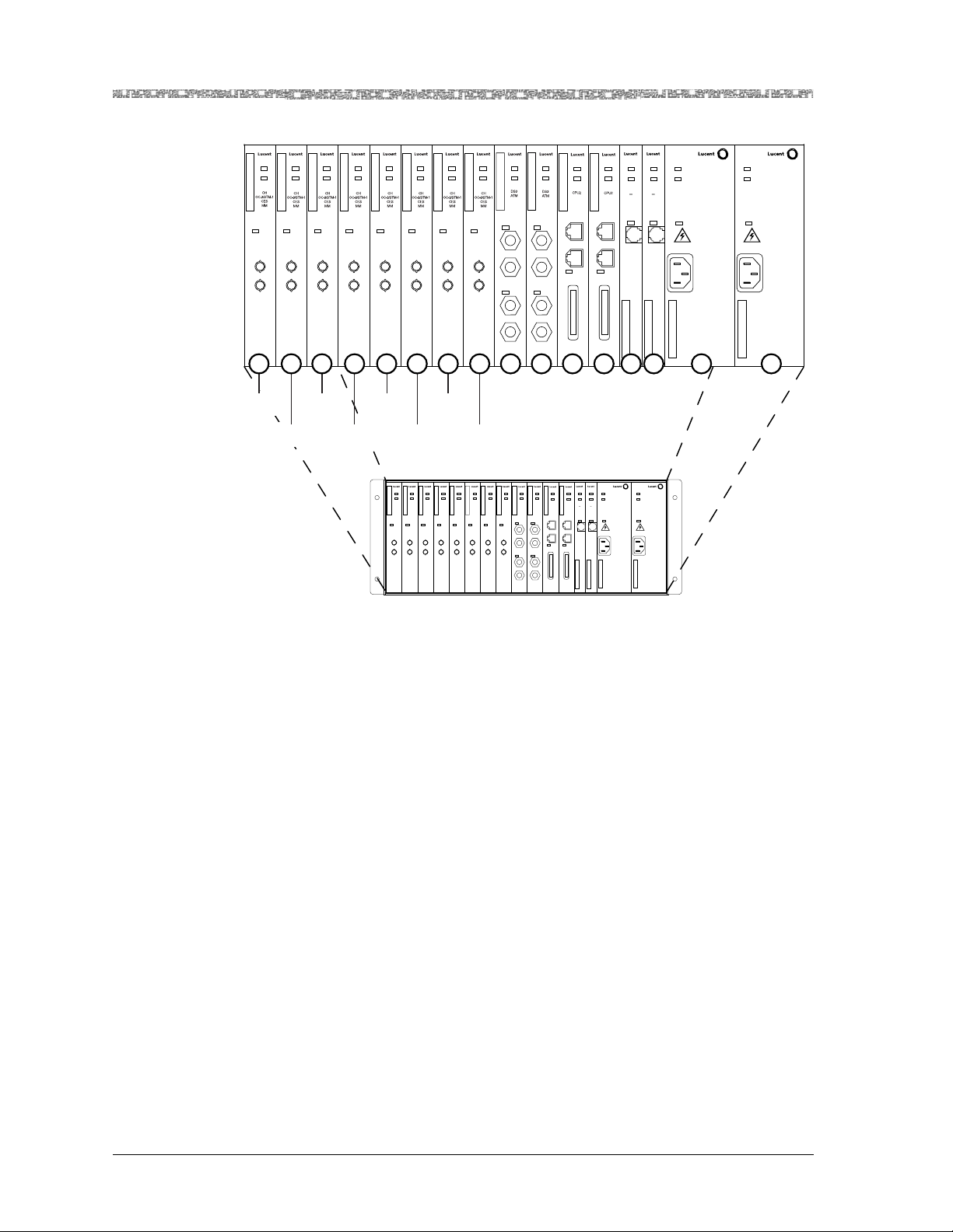
Chapter 4 Configuring the STM-1 Mode Ports and Channels Using the Console
Preparatory Steps Before Configuring the Module
FAIL
FAIL
FAIL
FAIL
FAIL
FAIL
FAIL
FAIL
FAIL
FAIL
ACTIVE
ACTIVE
ACTIVE
ACTIVE
ACTIVE
ACTIVE
ACTIVE
ACTIVE
ACTIVE
LOS
LOS
LOS
LOS
LOS
LOS
LOS
TX
TX
TX
TX
TX
TX
TX
RX
RX
RX
RX
RX
RX
RX
LOS
LOS
TX
RX
TX
RX
LOS
TX
RX
FAIL
ACTIVE
ACTIVE
ACTIVE
ETHERNET
CONSOLE
KEY
ETHERNET
CONSOLE
LOAD
KEY
LOS
TX
RX
LOS
TX
RX
1 2 3 4 5 6 7 8 9 10 11 12 21 22 23 24
FAIL
FAIL
FAIL
ACTIVE
STRATUM
CLK LOS
ACTIVE
ACTIVE
STRATUM
Power Supply
3 4
3 4
CLK LOS
LOAD
FAIL
FAIL
ACTIVE
Power Supply
Working
Module
Protection
Module
Working
Module
Protection
Module
Working
Module
LOS
TX
RX
Protection
Module
FAIL
FAIL
ACTIVE
ACTIVE
OC-3c
OC-3c
MM
MM
APS
APS
LOS
TX
RX
FAIL
ACTIVE
OC-3c
MM
APS
LOS
TX
RX
Working
Module
FAIL
ACTIVE
OC-3c
MM
APS
LOS
LOS
TX
TX
RX
RX
Protection
Module
FAIL
FAIL
ACTIVE
ACTIVE
OC-3c
OC-3c
MM
MM
APS
APS
LOS
TX
RX
FAIL
FAIL
FAIL
ACTIVE
OC-3c
MM
APS
LOS
TX
RX
FAIL
ACTIVE
ACTIVE
ACTIVE
OC-3c
DS3
DS3
MM
ATM
ATM
APS
LOS
LOS
LOS
TX
TX
RX
RX
TX
RX
LOS
LOS
TX
TX
RX
RX
FAIL
FAIL
FAIL
FAIL
ACTIVE
ACTIVE
ACTIVE
ACTIVE
STRATUM
STRATUM
CPU
CPU
3 4
3 4
CLK LOS
CLK LOS
ETHERNET
ETHERNET
CONSOLE
CONSOLE
LOAD
LOAD
KEY
KEY
FAIL
ACTIVE
Power Supply
FAIL
ACTIVE
Power Supply
Figure 4-1. Working and Protection Modules in a PSAX 1250 Chassis
Figure 4-2 shows a working and protection module setup on the PacketStar
PSAX 2300 chassis.
PacketStar® PSAX 1-Port Channelized OC-3/STM-1 CES Module User Guide, Issue 1 Release 11.0.0
4-2 255-700-714R11.0

Chapter 4 Configuring the STM-1 Mode Ports and Channels Using the Console
Preparatory Steps Before Configuring the Module
FAIL
FAIL
FAIL
FAIL
FAIL
FAIL
FAIL
ACTIVE
ACTIVE
ACTIVE
ACTIVE
ACTIVE
LOS
LOS
LOS
LOS
LOS
TX
TX
TX
TX
TX
RX
RX
RX
RX
RX
FAIL
ACTIVE
ACTIVE
LOS
LOS
LOS
TX
TX
TX
RX
RX
RX
1 2 3 4 5 6 7 8 A B 9 10 11 12 13 14 15 16 17
Working
Module
Protection
Module
Working
Module
Protection
Module
Working
Module
Protection
Module
Working
Module
Protection
Module
ACTIVE
FAIL
FAIL
FAIL
FAIL
LOS
TX
RX
ACTIVE
Protection
FAIL
ACTIVE
LOS
TX
RX
Module
FAIL
FAIL
FAIL
ACTIVE
ACTIVE
LOS
LOS
1
1
2
2
3
3
4
4
5
5
6
6
FAIL
ACTIVE
ACTIVE
ETHERNET
LOS
1
CONSOLE
2
LOAD
3
KEY
4
5
6
FAIL
ACTIVE
ACTIVE
ACTIVE
LOS
TX
RX
Module
ACTIVE
LOS
TX
RX
Protection
Module
Working
Module
UNLOCKED
STRATUM
3 4
CLK LOS
LAMP TEST
UNLOCKED
STRATUM
3 4
CLK LOS
LAMP TEST
Working
ACTIVE
ETHERNET
CONSOLE
KEY
FAIL
LOAD
PSAX 2300
FAIL
FAIL
FAIL
ACTIVE
ACTIVE
ACTIVE
OC-3c
OC-3c
OC-3c
MM
MM
MM
APS
APS
APS
LOS
LOS
LOS
TX
TX
TX
RX
RX
RX
FAIL
FAIL
ACTIVE
ACTIVE
OC-3c
OC-3c
MM
MM
APS
APS
LOS
LOS
TX
TX
RX
RX
FAIL
FAIL
FAIL
FAIL
FAIL
FAIL
FAIL
FAIL
ACTIVE
ACTIVE
ACTIVE
ACTIVE
ACTIVE
UNLOCKED
UNLOCKED
OC-3c
OC-3c
OC-3c
MM
MM
MM
STRATUM
STRATUM
APS
APS
APS
3 4
3 4
CLK LOS
CLK LOS
LOS
LOS
LOS
LAMP TEST
LAMP TEST
TX
TX
TX
RX
RX
RX
FAIL
FAIL
FAIL
FAIL
FAIL
ACTIVE
ACTIVE
ACTIVE
ACTIVE
OC-3c
MM
APS
LOS
TX
RX
ACTIVE
OC-3c
OC-3c
OC-3c
DS1
MM
MM
MM
Enh
APS
APS
APS
LOS
LOS
LOS
LOS
1
2
TX
TX
TX
3
RX
RX
RX
4
5
6
FAIL
ACTIVE
ACTIVE
ACTIVE
ACTIVE
DS1
DS1
CPU
CPU
Enh
Enh
ETHERNET
ETHERNET
LOS
LOS
1
1
CONSOLE
CONSOLE
2
2
LOAD
LOAD
3
3
KEY
KEY
4
4
5
5
6
6
Figure 4-2. Working and Protection Module Pairs in a PSAX 2300 Chassis
Note: Figure 4-2 shows the maximum protection scheme for a fully non-
blocking configuration.
Figure 4-3 shows an example of fiber optic links between working and protection modules between a PSAX 1250 and a PSAX 2300 chassis. If the primary on the PSAX 2300 fails, the primary on the PSAX 1250 becomes active,
or vice versa.
PacketStar® PSAX 1-Port Channelized OC-3/STM-1 CES Module User Guide, Issue 1 Release 11.0.0
255-700-714R11.0 4-3

Chapter 4 Configuring the STM-1 Mode Ports and Channels Using the Console
Loopback Option
PSAX 2300
FAIL
FAIL
FAIL
FAIL
FAIL
ACTIVE
ACTIVE
ACTIVE
OC-3c
OC-3c
MM
APS
LOS
LOS
TX
TX
RX
RX
ACTIVE
OC-3c
SOC-3c
MM
MM
APS
MM
APS
APS
LOS
LOS
TX
TX
RX
RX
FAIL
ACTIVE
ACTIVE
STM-1
STM-1
MM
MM
MSP
MSP
LOS
LOS
TX
TX
RX
RX
Working Module (Active)
Protection Module (Redundant)
Note: All connections between chassis are fiber optic links
FAIL
FAIL
FAIL
FAIL
FAIL
FAIL
ACTIVE
ACTIVE
ACTIVE
ACTIVE
SOC-3c
OC-3c
OC-3c
MM
MM
APS
APS
LOS
LOS
LOS
TX
TX
RX
TX
RX
RX
ACTIVE
OC-3c
OC-3c
MM
MM
APS
MM
APS
APS
LOS
LOS
TX
TX
RX
RX
FAIL
ACTIVE
ACTIVE
STM-1
STM-1
MM
MM
MSP
MSP
LOS
LOS
TX
TX
RX
RX
Figure 4-3. Fiber Optic Links Between Working and Protection Modules on a PSAX 1250
and a PSAX 2300 Chassis
Loopback Option
To aid network troubleshooting and testing, loopback capability is provided
for the 1-Port Channelized OC-3/STM-1 CES modules. The loopback option
on the module’s port and channel configuration window for the module
enables you to verify the integrity of a port by transmitting a received signal
back to the source. Selecting a loopback option is described in the module
configuration procedures.
Figure 4-4 illustrates the line loop and local loop options.
PacketStar® PSAX 1-Port Channelized OC-3/STM-1 CES Module User Guide, Issue 1 Release 11.0.0
4-4 255-700-714R11.0

Chapter 4 Configuring the STM-1 Mode Ports and Channels Using the Console
Loopback Option
Figure 4-4. Loopback Configuration Options
The following modules offer loopback capability:
20N73 1-Port OC-3c 1+1 APS Single-Mode
20N72 1-Port OC-3c 1+1 APS Multimode
23N02 3-Port Unstructured DS3/E3 CES
23N12 1-Port Channelized OC-3/STM-1 CES Multimode
23N13 1-Port Channelized OC-3/STM-1 CES Single-mode
23N74 3-Port DS3/E3 ATM
23N75 1-Port Channelized OC-3/STM-1 Unstructured CES/ATM
Multimode
23N76 1-Port Channelized OC-3/STM-1 Unstructured CES/ATM
Single-Mode
24N70 2-Port OC-3c/STM-1 ATM Multimode
24N71 2-Port OC-3c/STM-1 ATM Single-Mode
24N72 4-Port OC-3c/STM-1 Multimode
24N73 4-Port OC-3c/STM-1 Single-Mode
24N74 2-Port OC-3c/STM-1 Enhanced ATM Multimode
24N75 2-Port OC-3c/STM-1 Enhanced ATM Single-Mode
PacketStar® PSAX 1-Port Channelized OC-3/STM-1 CES Module User Guide, Issue 1 Release 11.0.0
255-700-714R11.0 4-5

Chapter 4 Configuring the STM-1 Mode Ports and Channels Using the Console
d
Obtaining General Module Data and Accessing Ports and Channels
Obtaining General Module Data and Accessing Ports and
Channels
This section describes how to obtain product, model, version, and serial number data about a module from the Equipment Configuration window. In
addition, the window provides operational status and alarm conditions on
each installed module. You also use this window to access the port and channel configuration windows for the PSAX modules.
Accessing the Equipment Configuration Window
Begin
1 On the Console Interface Main Menu window (see Figure 4-5), select the
Equipment Configuration option.
The Equipment Configuration window is displayed (see Figure 4-5
through Figure 4-7). Table 4-1 describes the commands on the windows;
Table 4-2 describes the fields on the windows. The alarm status descriptions for the Alarm Status field on the Equipment Configuration window
are provided in Table 4-3.
2 View the operational and alarm status, software version, PEC, and serial
number data of the installed modules.
3 When you are ready to begin configuring the ports and channels of the
module, select the line displaying the name of the module you want to
configure.
4 Proceed to the section entitled, “Configuring All Channels on a Port
(Channelization Disabled)” on page 4-10.
En
Figure 4-5. Console Interface Main Menu (Equipment Configuration Selected)
PacketStar® PSAX 1-Port Channelized OC-3/STM-1 CES Module User Guide, Issue 1 Release 11.0.0
4-6 255-700-714R11.0

Chapter 4 Configuring the STM-1 Mode Ports and Channels Using the Console
Obtaining General Module Data and Accessing Ports and Channels
Figure 4-6. Sample Equipment Configuration Window on a PSAX 4500 System
(Page 1)
Figure 4-7. Sample Equipment Configuration Window on a PSAX 1000,
PSAX 2300, or PSAX 4500 System (Page 2)
Commands The commands on this window have the following functions.
PacketStar® PSAX 1-Port Channelized OC-3/STM-1 CES Module User Guide, Issue 1 Release 11.0.0
255-700-714R11.0 4-7

Chapter 4 Configuring the STM-1 Mode Ports and Channels Using the Console
Obtaining General Module Data and Accessing Ports and Channels
Table 4-1. Equipment Configuration Window Commands
Command Function
Update Display Refreshes the current status of the modules in the PSAX chassis.
Page Down Displays the second page of the Equipment Configuration win-
dow. This command toggles with Page Up.
Page Up Displays the first page of the Equipment Configuration window.
This command toggles with Page Down.
Interface by Name Displays the Interface Name Table window on which you can
view all the interface names in the PSAX system.
Go Back to Main Menu Redisplays the Console Interface Main Menu window.
The display-only fields on this window are described in Table 4-2.
Table 4-2. Equipment Configuration Window Field Descriptions
Field Name Field Value Description
Slot Default: N/A
Displays the slot number in the PSAX chassis.
Range: 1–25,
depends on chassis
Format: Numeric
Module Type Default: N/A
Range: N/A
Format: Predefined
Displays the type of the module in the slot. When a module
is inserted into the chassis, its name is displayed in the Module Type field next to the slot number. When the module is
removed from the chassis, its name is no longer displayed in
the Module Type field and is replaced with None.
Status Default: Unknown
Displays the operational status of the module.
Range: N/A
Format: Predefined
Unknown Indicates the module has not been configured.
Primary Indicates one of the following:
• at least one port or channel on an I/O module has been
configured.
• a CPU module is functioning as the primary CPU module.
Standby Indicates one of the following:
• a module in redundant systems is operating as the
standby (backup) module to the primary (active) module.
• a CPU module in redundant systems is functioning as the
standby (backup) CPU module.
Alarm Status Default: No Alarm
Range: N/A
Format: Predefined
Displays the present alarm condition of the module. For the
alarm status conditions, see the table “Module Alarm Status
Descriptions on the Equipment Configuration Window” following this table. The generated alarms are also displayed in
the Active Alarm Status Table when the Alarm Status Table
feature is enabled (see Chapter 11 for additional information.
PacketStar® PSAX 1-Port Channelized OC-3/STM-1 CES Module User Guide, Issue 1 Release 11.0.0
4-8 255-700-714R11.0

Chapter 4 Configuring the STM-1 Mode Ports and Channels Using the Console
Obtaining General Module Data and Accessing Ports and Channels
Table 4-2. Equipment Configuration Window Field Descriptions (Continued)
Field Name Field Value Description
SW # Default: N/A
Range: N/A
Format: Predefined
Displays the version of PSAX system software with which
the modules’ firmware was released. The software version is
encoded in the module firmware. Because not all modules
require firmware upgrades with every new PSAX system
software release, the software version that is displayed in
this window may be lower than the CPU system software
that is currently running on the PSAX system. See the most
recent Release Note document for the latest software and
firmware lineup information.
PEC Default: N/A
Range: N/A
Format: Predefined
Serial # Default: N/A
Range: N/A
Format: Predefined
Displays the product element code (PEC) used to identify
and order this type of module. The PEC is encoded in the
module bootloader.
Displays the unique serial number of the individual module.
The product serial number is encoded in the module firmware.
For PSAX System Rel. 6.5.0 and later: 12-digit number in
the format, YYVVDDnnnnnn, where YY = year of manufacture VV = vendor ID code (manufacturer and location) DD =
date code of manufacture (either month or week depending
on vendor preference) nnnnnn = sequential number, which
in conjunction with YY, VV, and DD, creates a unique num-
ber for each hardware component in the PSAX product line.
For existing products with the 10-digit serial number used
in Rel. 6.5.0 or later, this number is displayed with two preceding zeros.
For PSAX Rel. 6.3.0 and earlier: 10-digit number. For products with 12-digit serial numbers used in Rel 6.3.0 or earlier
systems, the first two digits (YY) are not displayed.
The Alarm Status field on the Equipment Configuration window is described
in Table 4-3.
Table 4-3. Module Alarm Status Descriptions on the Equipment Configuration Window
Alarm Status
Module Type
Affected
Description
NoAlarm I/O and Server Indicates that no alarms have been detected for the module
in this slot.
WrongCardType I/O and Server Indicates that one type of module was configured in this
slot in the chassis, but a now different module occupies this
slot.
LineFailed All Indicates that the module in this slot is no longer receiving
or transmitting signals because the line failed.
PacketStar® PSAX 1-Port Channelized OC-3/STM-1 CES Module User Guide, Issue 1 Release 11.0.0
255-700-714R11.0 4-9

Chapter 4 Configuring the STM-1 Mode Ports and Channels Using the Console
Configuring All Channels on a Port (Channelization Disabled)
Table 4-3. Module Alarm Status Descriptions on the Equipment Configuration Window (Continued)
Alarm Status
Hexadecimal format,
Example:
12345678ABC
CardRemoved All Indicates that one of the following events occurred:
ReferenceClockFailed Stratum 3–4 Indicates that the timing reference clock on the Stratum
CompositeClockFailed Stratum 3–4 Indicates that the timing composite clock on the Stratum
Overload Power Supply Indicates that the Power Supply module is operating under
PowerFailed Power Supply Indicates that the power has failed.
Minus48vFailed Power Supply Indicates that the -48 V dc Power Supply module output
UnknownAlarm I/O and Server Indicates that the reason for failure is not known.
CompleteClockFailed Stratum 3–4 Indicates that the backplane detected a clock error.
PowerFailed Power Supply Indicates that no power is coming into the PSAX chassis.
Module Type
Affected
I/O and Server Indicates that one or more ports on the module in this slot
currently have a loss of signal. The numbers indicate which
ports have a loss of signal. For modules that have more
than eight ports not receiving signals, the value in this field
is in hexadecimal format.
• The module in this slot was configured and then
removed from the slot.
• Connections on the OC-3, OC-12, STM-1, or STM-4
APS/MSP primary module in this slot were transferred to
the standby module. After the transfer occurs, the former
primary module then displays CardRemoved in the
Alarm Status field; the former standby module then displays Primary in the Status field.
module in this slot failed.
module in this slot failed.
an overload condition.
failed.
Description
Configuring All Channels on a Port (Channelization
Disabled)
To configure all channels on a port (channelization disabled), use the following procedure.
Note: The window samples in this chapter display “SM” in the window
titles, for the single-mode module. The multimode modules have
the same window fields and commands on their windows, but display “MM” in the window titles. This guide shows only the SM
windows, for illustration purposes only. If you are configuring the
MM module, you will see “MM” instead of “SM”.
PacketStar® PSAX 1-Port Channelized OC-3/STM-1 CES Module User Guide, Issue 1 Release 11.0.0
4-10 255-700-714R11.0
 Loading...