

Page 1

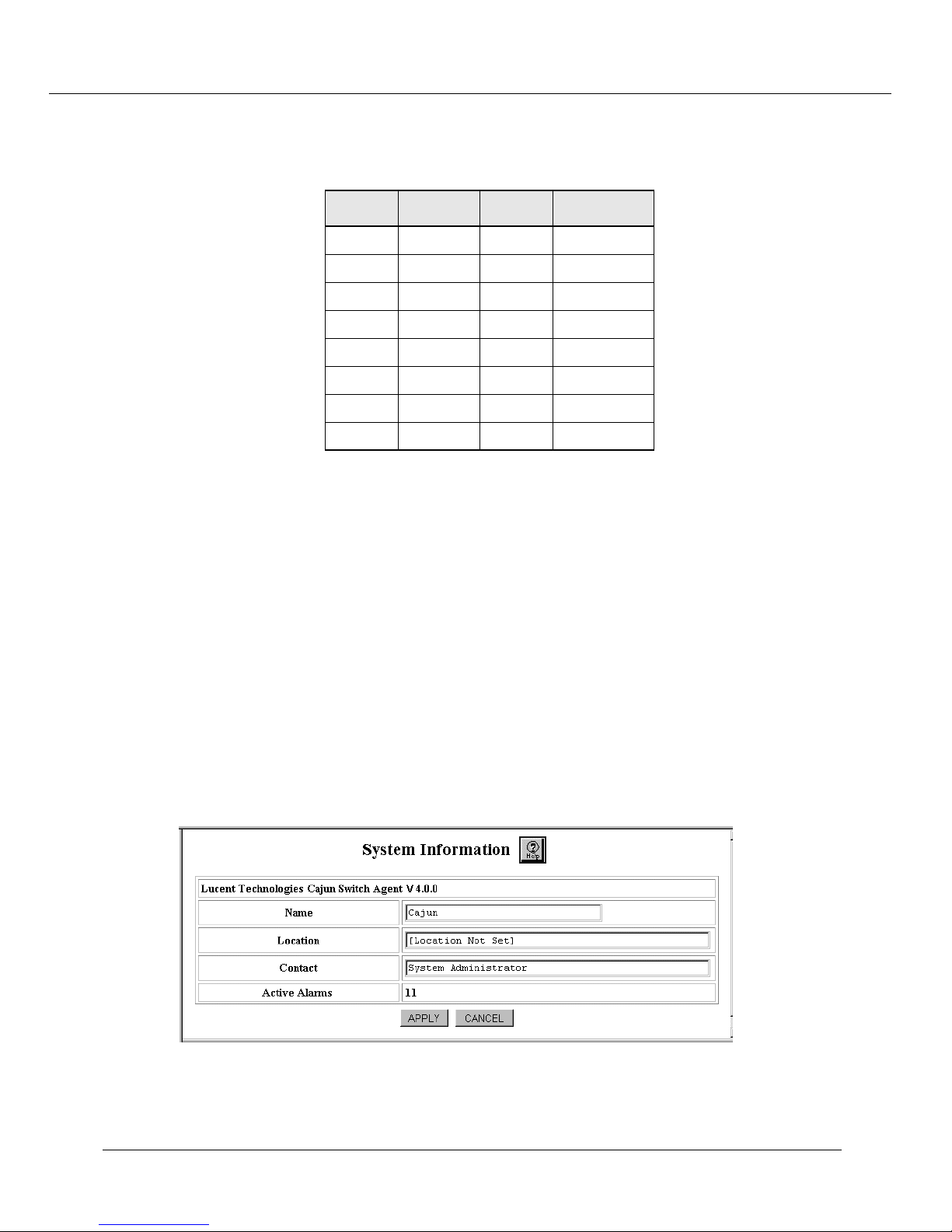
Cajun™ P550™ Switch
Installation Guide
Version 4.0
Page 2

Cajun P550 Switch 4.0 Installation Guide
© Copyright LUCENT TECHNOLOGIES 1999 ALL RIGHTS RESERVED
Printed in USA, November 1999
The products, specifications , and other technical inf ormation regarding the products contained in this document are subject to
change without notice. All information in this document is bel ieved to be accurate and reliable, but is pres ented witho ut warrant y
of any kind, express or implied, and users must take full responsibility for their applica tion of any products speci fied in this
document. Lucent disclaims responsibility for errors which may appear in this document, and it reserves the right, in its sole
discretion and without notice, to make substitutions and modifications in the products and practices described in this document.
Lucent, Cajun, CajunDocs, OpenT runk, P550, and CajunView are trademar ks of Lucent Technologies.
Microsoft , Wind ow s, Win dow s NT , Wind ow s 95, Win dow s 98, and Internet Explor er are trademarks or registered trademarks o f
Microsoft Corporation in the U.S. and/or other countries.
OpenView is a trademark of Hewlett Packard Comapny.
Netscape and Netscape N avigator are registered trademarks of N etscape Commu nications Corpor ation in the U nited States and
other countries.
3Com is a registered trademark and PACE is a trademark of 3Com or its subsidiaries.
Sun, Sun Micro systems, and Solaris are trademarks or registered trademarks of Sun Microsystems, Inc. in the U.S. and certain
other countries.
Bay Networks and System 5000 are registered trade marks of Nort el Networks .
Cisc o Ca ta ly st 5000 is a registere d trademar k of Cisco Sy stem Incorporat ed .
Adobe is a registered trademark of Adobe Systems Incorporated.
ALL OTHER TRADEMARKS MENTIONED IN THIS DOCUMENT ARE PROPERTY OF THEIR RESPECTIVE OWNERS.
Document Number - 610-0117-061
Page 3

Contents
Preface
Overview of The Contents . . . . . . . . . . . . . . . . . . . . . . . . . . . . . . . . . . . . . . . . . . . . . . . . . . . . vii
Documentation Feedback . . . . . . . . . . . . . . . . . . . . . . . . . . . . . . . . . . . . . . . . . . . . . . . . . . . . . vii
Online Documentation . . . . . . . . . . . . . . . . . . . . . . . . . . . . . . . . . . . . . . . . . . . . . . . . . . . . . . . vii
Conventions . . . . . . . . . . . . . . . . . . . . . . . . . . . . . . . . . . . . . . . . . . . . . . . . . . . . . . . . . . . . . . . viii
Audience . . . . . . . . . . . . . . . . . . . . . . . . . . . . . . . . . . . . . . . . . . . . . . . . . . . . . . . . . . . . . . . . . . viii
Related Documents . . . . . . . . . . . . . . . . . . . . . . . . . . . . . . . . . . . . . . . . . . . . . . . . . . . . . . . . . . viii
Lucent Documents . . . . . . . . . . . . . . . . . . . . . . . . . . . . . . . . . . . . . . . . . . . . . . . . . . . . . . . .ix
Reference Documents . . . . . . . . . . . . . . . . . . . . . . . . . . . . . . . . . . . . . . . . . . . . . . . . . . . . . . ix
Terminology . . . . . . . . . . . . . . . . . . . . . . . . . . . . . . . . . . . . . . . . . . . . . . . . . . . . . . . . . . . . . . . . ix
Contacting Lucent Corporation . . . . . . . . . . . . . . . . . . . . . . . . . . . . . . . . . . . . . . . . . . . . . . . . .ix
Chapter 1 — Unpacking and Installing the Cajun P550 Switch
Overview . . . . . . . . . . . . . . . . . . . . . . . . . . . . . . . . . . . . . . . . . . . . . . . . . . . . . . . . . . . . . . . . . .1-1
Unpacking the System . . . . . . . . . . . . . . . . . . . . . . . . . . . . . . . . . . . . . . . . . . . . . . . . . . . . . . .1-1
Selecting a Location . . . . . . . . . . . . . . . . . . . . . . . . . . . . . . . . . . . . . . . . . . . . . . . . . . . . . . . . .1-2
Installing the System . . . . . . . . . . . . . . . . . . . . . . . . . . . . . . . . . . . . . . . . . . . . . . . . . . . . . . . . . 1-3
Preventing Electrostatic Discharge . . . . . . . . . . . . . . . . . . . . . . . . . . . . . . . . . . . . . . . . . . .1-3
Installing the Chassis . . . . . . . . . . . . . . . . . . . . . . . . . . . . . . . . . . . . . . . . . . . . . . . . . . . . . .1-3
Rack Mounting the System . . . . . . . . . . . . . . . . . . . . . . . . . . . . . . . . . . . . . . . . . . . . . .1-4
Installing the System on a Table Top . . . . . . . . . . . . . . . . . . . . . . . . . . . . . . . . . . . . . .1-5
Installing the Modules . . . . . . . . . . . . . . . . . . . . . . . . . . . . . . . . . . . . . . . . . . . . . . . . . . . .1-6
Auto Negotiation Issues . . . . . . . . . . . . . . . . . . . . . . . . . . . . . . . . . . . . . . . . . . . . . . . .1-7
Installing the Cables . . . . . . . . . . . . . . . . . . . . . . . . . . . . . . . . . . . . . . . . . . . . . . . . . . . . . .1-7
Recommended Cable Distances . . . . . . . . . . . . . . . . . . . . . . . . . . . . . . . . . . . . . . . . . .1-8
Ensuring that You Have Enough Power Available . . . . . . . . . . . . . . . . . . . . . . . . . . . . . . .1-9
Connecting the Power Supplies . . . . . . . . . . . . . . . . . . . . . . . . . . . . . . . . . . . . . . . . . . . .1-10
Powering On the System . . . . . . . . . . . . . . . . . . . . . . . . . . . . . . . . . . . . . . . . . . . . . . . . .1-10
Power-On Sequence . . . . . . . . . . . . . . . . . . . . . . . . . . . . . . . . . . . . . . . . . . . . . . . . . .1-10
Post Power-on Configuration . . . . . . . . . . . . . . . . . . . . . . . . . . . . . . . . . . . . . . . . . . .1-11
Chapter 2 — Configuring the Cajun P550 Switch (Layer 2 & Layer 3)
Terminal Settings . . . . . . . . . . . . . . . . . . . . . . . . . . . . . . . . . . . . . . . . . . . . . . . . . . . . . . . . . . .2-1
Configuring the Supervisor Module Using the CLI . . . . . . . . . . . . . . . . . . . . . . . . . . . . . . . . .2-1
Configuring the Switch Using the Web Agent . . . . . . . . . . . . . . . . . . . . . . . . . . . . . . . . . . . . .2-5
Logging In to the Web Agent . . . . . . . . . . . . . . . . . . . . . . . . . . . . . . . . . . . . . . . . . . . . . . .2-6
Setting Up User Accounts . . . . . . . . . . . . . . . . . . . . . . . . . . . . . . . . . . . . . . . . . . . . . . . . . .2-6
Configuring Port Parameters Using the Web Agent . . . . . . . . . . . . . . . . . . . . . . . . . . . . . . . . .2-7
Configuring Physical Port Parameters on Gigabit Ports . . . . . . . . . . . . . . . . . . . . . . . . . . .2-7
Configuring Physical Port Parameters on Fast Ethernet Ports . . . . . . . . . . . . . . . . . . . . . .2-9
Using the All Ports Configuration Dialog Box . . . . . . . . . . . . . . . . . . . . . . . . . . . . . . . . .2-12
Viewing Switch Port Parameters . . . . . . . . . . . . . . . . . . . . . . . . . . . . . . . . . . . . . . . . . . . .2-13
Cajun P550 Switch Installation Guide
iii
Page 4

Configuring Switch Port Parameters . . . . . . . . . . . . . . . . . . . . . . . . . . . . . . . . . . . . . . . . .2-13
Configuring Port VLAN Parameters . . . . . . . . . . . . . . . . . . . . . . . . . . . . . . . . . . . . . . . . .2-16
Configuring VTP Snooping . . . . . . . . . . . . . . . . . . . . . . . . . . . . . . . . . . . . . . . . . . . . . . . .2-18
Configuring Non-VLAN Switch Port Parameters . . . . . . . . . . . . . . . . . . . . . . . . . . . . . . .2-19
Examples of Switch Ports Settings for Various VLAN Connection Types . . . . . . . . . .2-20
Configuring Fast Start Mode . . . . . . . . . . . . . . . . . . . . . . . . . . . . . . . . . . . . . . . . . . . .2-21
Using the All Ports Configuration Dialog Box . . . . . . . . . . . . . . . . . . . . . . . . . . . . . . . . .2-22
Setting Up SNMP Communities . . . . . . . . . . . . . . . . . . . . . . . . . . . . . . . . . . . . . . . . . . . .2-23
Changing the Console Serial Port Settings . . . . . . . . . . . . . . . . . . . . . . . . . . . . . . . . . . . .2-24
Configuring the Serial Console Port as a TTY Console . . . . . . . . . . . . . . . . . . . . . . . .2-25
Connecting a Modem . . . . . . . . . . . . . . . . . . . . . . . . . . . . . . . . . . . . . . . . . . . . . . . . .2-25
Configuring the Serial Console Port as a PPP Console . . . . . . . . . . . . . . . . . . . . . . . .2-26
Regaining Configuration Access to the PPP Serial Port Console . . . . . . . . . . . . . . . . .2-27
Configuring Dial-Up Networking . . . . . . . . . . . . . . . . . . . . . . . . . . . . . . . . . . . . . . . .2-28
Using Dial-Up Networking with a PPP Serial Port Console . . . . . . . . . . . . . . . . . . . .2-29
Configuring the IP Interface for the PPP Console . . . . . . . . . . . . . . . . . . . . . . . . . . . .2-29
Configuring a Static Route for the PPP Console . . . . . . . . . . . . . . . . . . . . . . . . . . . . .2-30
Hardware Requirements for Routing . . . . . . . . . . . . . . . . . . . . . . . . . . . . . . . . . . . . . . . .2-30
Configuring IP Routing on the Switch . . . . . . . . . . . . . . . . . . . . . . . . . . . . . . . . . . . . . . .2-31
Minimum IP Routing Configuration Requirements . . . . . . . . . . . . . . . . . . . . . . . . . .2-31
Routing Configuration Quickstart . . . . . . . . . . . . . . . . . . . . . . . . . . . . . . . . . . . . . . . .2-31
Configuring System Information . . . . . . . . . . . . . . . . . . . . . . . . . . . . . . . . . . . . . . . . . . . . . .2-32
Entering General System Information . . . . . . . . . . . . . . . . . . . . . . . . . . . . . . . . . . . . . . .2-32
Enabling SNTP . . . . . . . . . . . . . . . . . . . . . . . . . . . . . . . . . . . . . . . . . . . . . . . . . . . . . . . . .2-33
Setting Summer Time Hours . . . . . . . . . . . . . . . . . . . . . . . . . . . . . . . . . . . . . . . . . . . . . . .2-34
Setting Recurring Summer Time Hours . . . . . . . . . . . . . . . . . . . . . . . . . . . . . . . . . . .2-34
Setting One-Time Summer Time Hours . . . . . . . . . . . . . . . . . . . . . . . . . . . . . . . . . . .2-36
Setting the System Clock . . . . . . . . . . . . . . . . . . . . . . . . . . . . . . . . . . . . . . . . . . . . . . . . .2-38
Setting the Temperature System . . . . . . . . . . . . . . . . . . . . . . . . . . . . . . . . . . . . . . . . . . . .2-39
Displaying the Power System Statistics . . . . . . . . . . . . . . . . . . . . . . . . . . . . . . . . . . . . . . .2-39
Displaying Cooling System Statistics . . . . . . . . . . . . . . . . . . . . . . . . . . . . . . . . . . . . . . . . .2-40
Configuring Redundant Hardware . . . . . . . . . . . . . . . . . . . . . . . . . . . . . . . . . . . . . . . . . .2-40
Installing Redundant Hardware . . . . . . . . . . . . . . . . . . . . . . . . . . . . . . . . . . . . . . . . .2-41
Replacing the Primary Controller . . . . . . . . . . . . . . . . . . . . . . . . . . . . . . . . . . . . . . . .2-43
Replacing an Element . . . . . . . . . . . . . . . . . . . . . . . . . . . . . . . . . . . . . . . . . . . . . . . . .2-44
Performing a System Reset . . . . . . . . . . . . . . . . . . . . . . . . . . . . . . . . . . . . . . . . . . . . . . . .2-45
Managing Configuration Files . . . . . . . . . . . . . . . . . . . . . . . . . . . . . . . . . . . . . . . . . . . . . . . . .2-45
Viewing Your Running Configuration . . . . . . . . . . . . . . . . . . . . . . . . . . . . . . . . . . . . . . .2-46
Viewing Your Startup Configuration . . . . . . . . . . . . . . . . . . . . . . . . . . . . . . . . . . . . . . . .2-46
Viewing Your Script Execution Log File . . . . . . . . . . . . . . . . . . . . . . . . . . . . . . . . . . . . . .2-46
Copying Configuration Files . . . . . . . . . . . . . . . . . . . . . . . . . . . . . . . . . . . . . . . . . . . . . . .2-46
Copying Running Configuration to Startup Configuration . . . . . . . . . . . . . . . . . . . .2-47
Copying Files . . . . . . . . . . . . . . . . . . . . . . . . . . . . . . . . . . . . . . . . . . . . . . . . . . . . . . . . . . .2-47
Viewing the Status of a TFTP Transfer . . . . . . . . . . . . . . . . . . . . . . . . . . . . . . . . . . . .2-50
iv Cajun P550 Switch Installation Guide
Page 5

Appendix A — Product Specifications
Power . . . . . . . . . . . . . . . . . . . . . . . . . . . . . . . . . . . . . . . . . . . . . . . . . . . . . . . . . . . . . . . . . . . A-1
Operating/Physical . . . . . . . . . . . . . . . . . . . . . . . . . . . . . . . . . . . . . . . . . . . . . . . . . . . . . . . . . A-1
Safety . . . . . . . . . . . . . . . . . . . . . . . . . . . . . . . . . . . . . . . . . . . . . . . . . . . . . . . . . . . . . . . . . . . A-1
EMI . . . . . . . . . . . . . . . . . . . . . . . . . . . . . . . . . . . . . . . . . . . . . . . . . . . . . . . . . . . . . . . . . . . . . A-1
Index
Cajun P550 Switch Installation Guide v
Page 6

vi Cajun P550 Switch Installation Guide
Page 7

Prefac e
This guide explains how to install, configure, and operate the Lucent P550 Cajun Switch.
It also includes information on the Command Line Interface (CLI) and information on
downloading new operational code to your switch.
Overview of The Contents
This guide contains the following chapters:
Chapter 1, Unpacking and Installing the Cajun P550 Switch
unpack and assemble your switch.
Chapter 2, Configuring the P550 Cajun Switch - Explains how to perform the initial
configuration of your switch, create users, and configure ports.
Appendix A, Product Specifications - Shows the specifications of your switch.
Index
Documentation Feedback
If you have comments about the technical accuracy or general quality of this document
please contact us at:
Please cite the document title, part number, and page reference, if appropriate.
Online Documentation
- Explains how to
Lucent Technologies maintains copies of all technical documentation on the corporate
web server. To access online documentation, including HTML and PDF documents, use
Netscape Navigator version 3.x or above or Internet Explorer version 3.x or above and
type the URL:
http: //pubs.lucentctc. com/
Cajun P550 Switch Installation Guide vii
Page 8

Preface
Conventions
This document uses the following conventions:
Convention Represents Examples
User Input User entered text. To create a new password, type
store password owl
Emphasis
Boldface Text Menu command
System Output Text displayed by
A new term, text
emphasis, or a
document title.
or button name.
the system.
The system settings are
saved to NVRAM if you use the store
command.
File | Save
Select
current work session.
Cancel
Click
installation.
If you attempt the find the physical
location of port 30, the system
displays
to cancel the
permanently
to save your
Unit 2 Port 2
Note: Provides additional information about a procedure or topic.
CAUTION:Indicates a condition that may damage hardware or software.
WARNING:Indicates a condition that may cause bodily injury or death. Before
working on equipment, ensure that you turn the power off and unplug
the equipment in question.
Failure to follow proper safety precautions can result in electrical shock.
Audience
This guide is intended for the following people at your site:
❒ Network manager or administrator
❒ Hardware installer
Related Documents
This section provides information on supporting documentation, including:
❒ Lucent Documents
viii
Cajun P550 Switch Installation Guide
Page 9

❒ Reference Documents
Lucent Documents
The following documents provide additional information on Lucent products:
Lucent CajunView User’s Guide - Describes the installation and use of Lucent’s Java-based,
multiswitch element management system.
Lucent Cajun P550 Operation Guide - Describes the configuration and operation of the
Cajun P550 switch.
Reference Documents
The following documents supply related background information:
❒ Internetworking with TCP/IP Volume I — 3rd Edition, Douglas E. Comer, ISBN
0-13-216987-8.
Preface
❒ Internet Routing Architectures — Cisco Press, Bassam Halabi
❒ Routing in the Internet — Christian Huitema, ISBN 0-13-132192-7
❒ Interconnections: Bridges and Routers — Radia Perlman, ISBN 0-201-56332-0
Terminology
Throughout the book, the term Layer 2, often followed by the abbreviation L2, is used to
indicate switching capabilities. For example, the name, Layer 2 Supervisor Module,
indicates a supervisor module that enables switching.
The terms, Multilayer and Layer 3, often followed by the abbreviation L3, refer to the
combined ability to switch and route. For example, the name, Multilayer Supervisor
Module, indicates a supervisor module that provides switching and routing capabilities.
Contacting Lucent Corporation
For information about Lucent Data Networking products and services, please consult the
Lucent World Wide Web site at http://www.lucent.com/dns.
If you have any questions, please call Technical Support:
Within the United States - 1-800-237-0016, press 0 at the prompt, then dial ext. 73300.
From outside the United States - 1-813-217-2425.
Cajun P550 Switch Installation Guide ix
Page 10

Preface
x
Cajun P550 Switch Installation Guide
Page 11

1
Unpacking and Installing the
Cajun P550 Switch
Overview
This chapter describes:
❒ Unpacking the System
❒ Installing the System
Unpacking the System
To unpack the system, check for the following components:
❒ Chassis, including:
• Power supply (installed in the switch)
• Fan tray
• Supervisor module
• Blank faceplates
❒ I/O modules (shipped separately)
❒ Rack mount kit (rack installation)
❒ Rubber feet (table top installation)
❒ Power cords (one for each power supply)
❒ 10Base-T crossover cable (for connecting to Ethernet Console Port)
❒ Out-of-Band connection kit, including:
• Male DCE-to-RJ-45 connector (connects to switch)
• Female DTE-to-RJ-45 connector (connects to computer)
• Male DTE-to-RJ-45 null modem connector (connects to a modem)
• Straight-through RJ-45 cable for connecting between connectors
Cajun P550 Switch Installation Guide 1-1
Page 12
Unpacking and Installing the Cajun P550 Switch
❒ Product documentation
❒ Options (as ordered)
Unpack the shipment and report any lost or damaged items to your shipping carrier or
Lucent representative.
Selecting a Location
The location you select for installing the system hardware must meet the following
requirements:
❒ 19-inch EIA-standard grounded rack or table capable of supporting at least 60 kg
(130 lb). A fully-loaded switch weighs 30 kg (65 lbs).
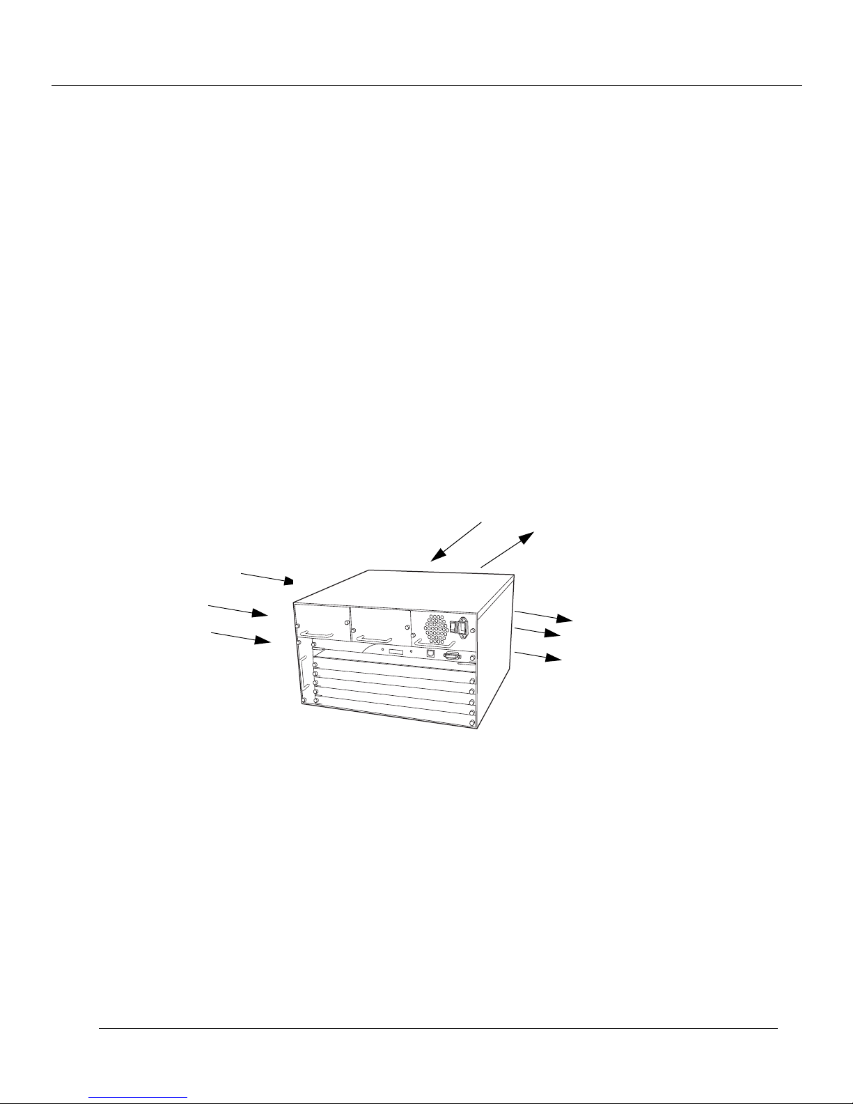
❒ At least 2 inches (5.2 cm) on either side of the system, and from the rear of the
system, to allow adequate airflow through the system (Figure 1-1.).
Figure 1-1. Selecting a Location
1-2
Air Flow
❒ AC power source(s) within 2 m (6 ft.) (separate sources, on separate circuits, if you
require maximum fault tolerance)
❒ Ambient temperature between 0°C and 40°C (32°F to 104°F)
❒ Relative humidity less than 95%, non-condensing
Cajun P550 Switch Installation Guide
Page 13

Installing the System
The process for installing the system requires the following tasks:
Preventing Electrostatic Discharge
1.
Installing the Chassis
2.
Installing the Modules
3.
Installing the Cables
4.
Ensuring that You Have Enough Power Available
5.
Connecting the Power Supplies
6.
Powering On the System
7.
Unpacking and Installing the Cajun P550 Switch
Note:
The Cajun P550 switch requires 16MB RAM for proper functioning.
Preventing Electrostatic Discharge
Protect the modules against damage from electrostatic discharge (ESD) by using a
grounded ESD wrist strap while installing and removing modules. While installing the
P550 Cajun Switch:
Ground the unit. The unit is grounded through the power cord when it is
1.
connected between the unit and the primary power source.
Lay out the static-dissipative work surface (ESD mat) on a flat surface.
2.
Connect the ground cord assembly to the ESD mat and to the ground plug on the
3.
switch fan tray.
Wear the ESD wrist strap and attach it to the ground cord assembly.
4.
Installing the Chassis
The system can be installed by:
❒ Rack Mounting the System
❒ Installing the System on a Table Top
Cajun P550 Switch Installation Guide 1-3
Page 14
Unpacking and Installing the Cajun P550 Switch
Rack Mounting the System
A fully loaded P550 Cajun Switch weighs 30 kg (65 lbs). Safe rackmount installation
requires three people: two to lift the system into place, and a third to screw the system to
the rack using a Phillips-head screwdriver.
WARNING:
Do not use the handles on the power supplies or fan assembly to lift the
system.
To rack mount the system:
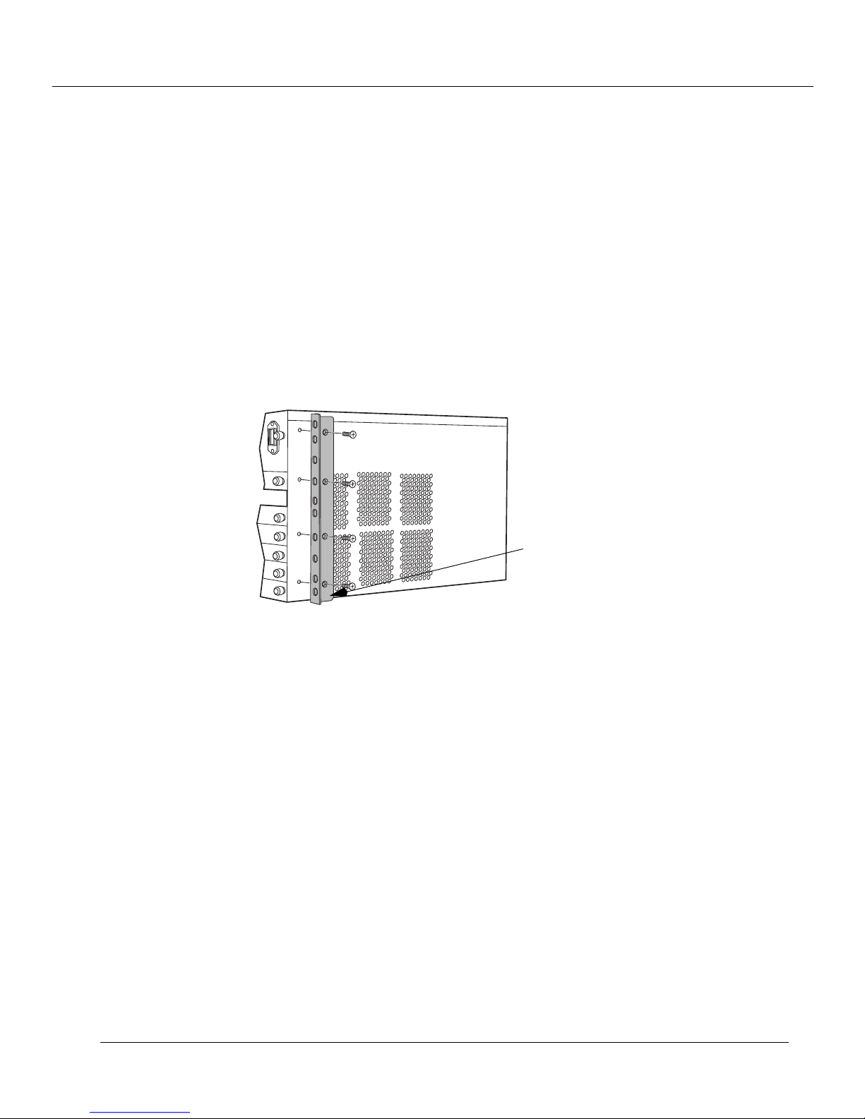
Install the rack mount flanges onto the system (Figure 1-2.).
1.
Figure 1-2. Rack Mounting the Switch
Rack Mounting
Flanges
1-4
2. Check that all pre-installed modules are securely installed:
• Check that the supervisor module is firmly installed.
• Check that the power supply and fan are securely in place.
• Tighten the large black screws on the module, power supply, and fan tray
faceplates.
3. With one person at each end of the system, lift the system into position. Use the
supplied screws to install the system into the rack (Figure 1-3.).
Cajun P550 Switch Installation Guide
Page 15
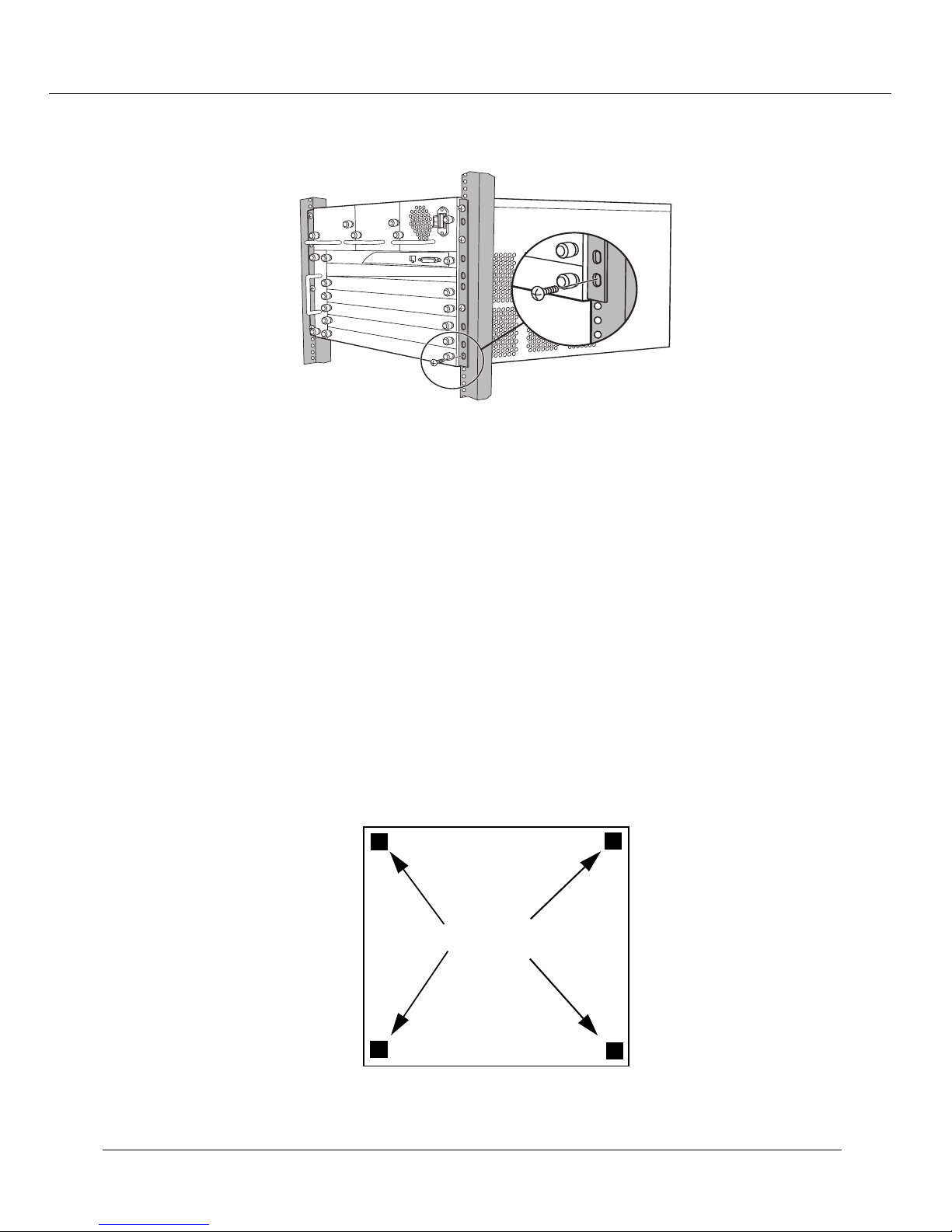
Figure 1-3. Securing the Modules
Installing the System on a Table Top
Unpacking and Installing the Cajun P550 Switch
To install the system on a table top:
WARNING:Do not use the handles on the power supplies or fan assembly to lift the
system.
1. Place the system on a surface that supports at least 60 kg (130 lb). The switch itself
weighs about 30 kg (65 lbs) fully loaded.
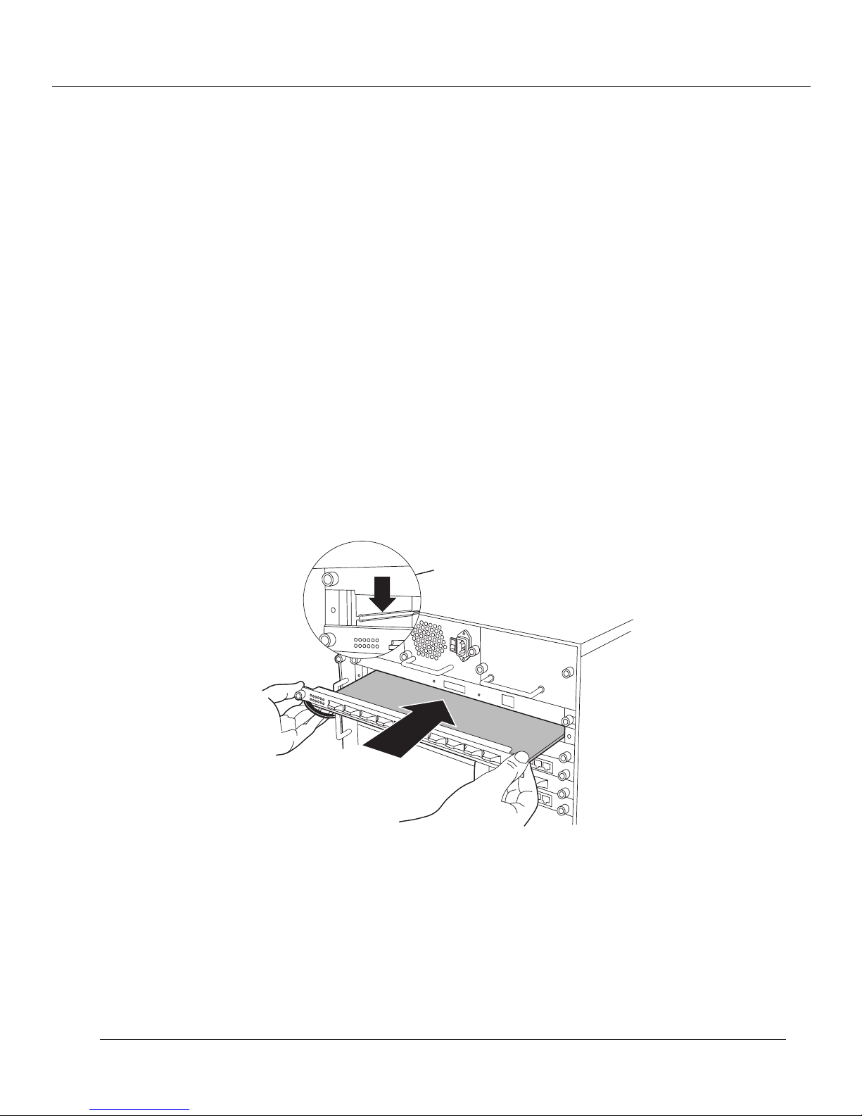
2. Apply the supplied rubber feet to the bottom of the unit, placing the feet about 1.3
cm (1/2 in.) from each corner of the unit (Figure 1-4.).
Figure 1-4. Table Top Installation
Rubber Feet
Cajun P550 Switch Installation Guide 1-5
Page 16
Unpacking and Installing the Cajun P550 Switch
3. Check that all pre-installed modules are securely installed:
• Check that the supervisor module is firmly installed
• Check that the power supply and fan are securely in place
• Tighten the large black screws on the module, power supply, and fan tray
faceplates.
Installing the Modules
To install modules in the system chassis:
1. Carefully remove each module from its box, leaving the module in its antistatic
wrapping.
2. After taking appropriate antistatic precautions, as described in "Preventing
Electrostatic Discharge”, earlier in the chapter, carefully remove the module from
the antistatic wrap.
3. Insert the module into the system (Figure 1-5.).
Figure 1-5. Inserting the Modules
4. Push the module most of the way into the system chassis. Use the ejectors to insert
the module into the system backplane (Figure 1-6.).
1-6
Cajun P550 Switch Installation Guide
Page 17
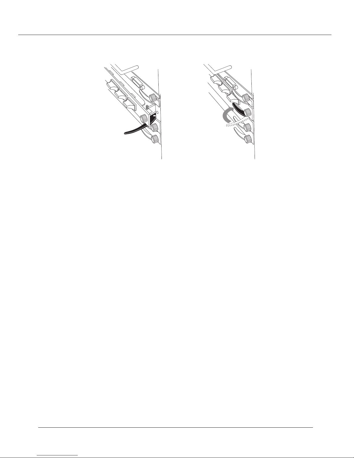
Figure 1-6. Using the Ejectors
5. Tighten the black captive screws.
Unpacking and Installing the Cajun P550 Switch
Ejector ClosedEjector Open
Auto Negotiation Issues
You may experience difficulties with auto-negotiation between some versions of the
10/100Base-TX module and adapter cards using physical interfaces manufactured by
National Semiconductor. The symptom is loss of connectivity.
You can address this problem by either disabling auto-negotiation and manually
configuring the speed and duplex of the mirror port and network card, or using a patch
cable longer than 5 meters.
Installing the Cables
Install appropriate cables for your network configuration. P550 Cajun switch cable types
include:
❒ Fiber cables with SC-type connectors
❒ Straight-through Category 5 cables with male RJ-45 connectors (end station/NIC
(network interface card) card connections). All I/O ports are crossed over internally
so you can use straight-through cables to attach to end stations.
❒ Crossover cables with male RJ-45 connectors (switch-to-switch connections).
The types of cable for the ethernet console (out-of-band) are different. Refer to Chapter
2, “Configuring the Cajun Switch (Layer 2 & Layer 3),” for more information.
Cajun P550 Switch Installation Guide 1-7
Page 18
Unpacking and Installing the Cajun P550 Switch
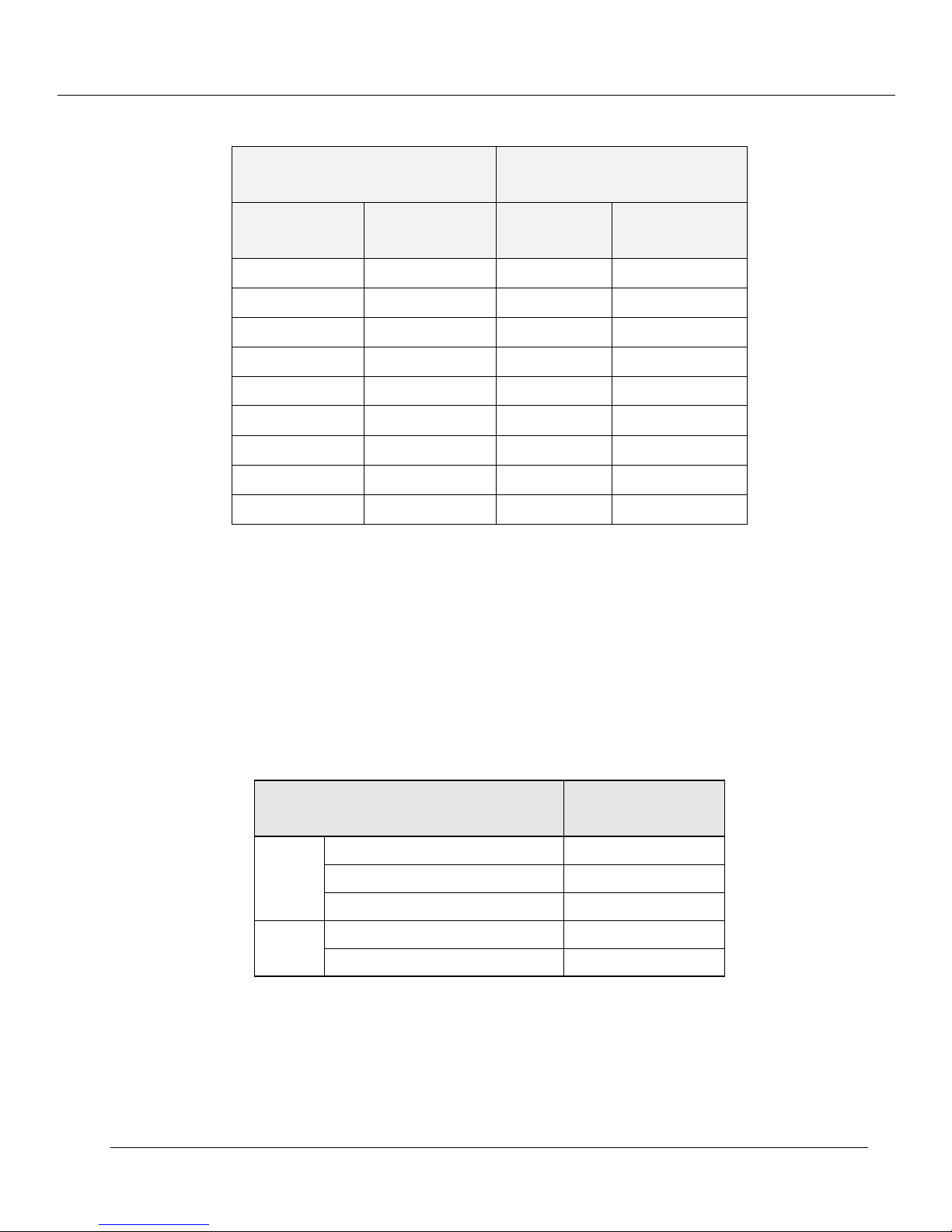
Table 1-1. Cable Pinouts
Pinout to 10Base-T Cables
Pin #
Signal
Description
1 Receive data (+) 1 DCD (output)
2 Receive data (-) 2 TX (output)
3 Transmit data (+) 3 RX (input)
4 Not used 4 DTR (input)
5 Not used 5 SGD (ground)
6 Transmit data (-) 6 DSR (not used)
7 Not used 7 RTS (not used)
8 Not used 8 CTS (output)
N/A N/A 9 RI (not used)
Recommended Cable Distances
Pinout for RS-232 DB-9
Female Console Port
Pin #
Signal
Description
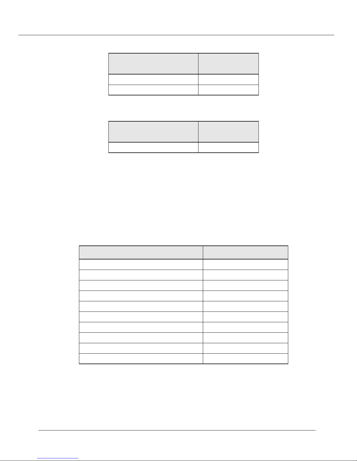
The following guidelines are based on IEEE 802.3z Draft Document, version 3.2.
Note: Tables 1-2 through 1-4 describe maximum link distances only. When building
half-duplex networks using Ethernet repeaters, you must also consider
maximum network diameter, which is not discussed in this document.
Table 1-2. Maximum Fiber Link Distances for Gigabit Links
Fiber Cable Description
50 micron multimode 550 m
1300
nm
850 nm
62.5 micron multimode 440 m
Singlemode fiber 5 km
50 micron multimode 550 m
62.5 micron multimode 260 m
Maximum Cable
Length
1-8
Cajun P550 Switch Installation Guide
Page 19
Unpacking and Installing the Cajun P550 Switch
Table 1-3. Maximum Fiber Link Distances for 100 Mb/s Links
Fiber Cable Description
Half-duplex connection 412 m
Full-duplex connection 2 km
Table 1-4. Maximum Copper Cable Lengths (10/100 Mb/sLinks)
Cable Description
Category 5 twisted pair cable 100 m
Maximum Cable
Length
Maximum Cable
Length
Ensuring that You Have Enough Power Available
Each power supply powers approximately three I/O modules. It takes two power
supplies to power a full chassis. Using three power supplies ensures that the system has
fault-tolerant load-sharing power capabilities.
Use Table 1-5 for the precise power values:
Table 1-5. Power Values for System Devices
Device Power Added/Used
Power Supply + 300 W
Backplane Elements - 50 W
20-Port 10/100 Module - 70 W
L2 Supervisor Module - 10 W
L3 Supervisor Module - 45 W
2-Port Gigabit Module (L2/L3) - 35 W
4-Port Gigabit Module - 55 W
10-Port 100Base-FX Module (L2) - 50 W
10-Port 100Base-FX Module (L3) - 60 W
12-Port 10/100Base-TX Module (L3) - 70 W
Note: See the instruction sheet included with the power supply for power supply
installation instructions.
Cajun P550 Switch Installation Guide 1-9
Page 20

Unpacking and Installing the Cajun P550 Switch
Connecting the Power Supplies
Before connecting the power cords:
Make sure that all of the power supplies are seated firmly, with the captive screws
❒
tightened.
Make sure that all of the ON/OFF switches on the power supplies are OFF.
❒
If you are using multiple power supplies to ensure fault tolerance, make sure that
❒
there is a dedicated power circuit available for each supply. The separate power
sources help ensure operation when the power source itself fails.
To connect the power supplies:
Plug the power cord into each power supply.
1.
Plug the power cord into an AC outlet.
2.
Powering On the System
To power on the system:
Check all connections.
1.
Turn on the power supplies by switching on the power switches on each supply.
2.
Power-On Sequence
As the system powers on:
Lucent P550 Cajun Switch Agent (M5500-SUP) v4.x.x
❒
LED display on the front panel of the switch.
On properly functioning modules, Port LEDs will cycle from yellow to normal
❒
operating status as the system continues through its power-on diagnostics.
When the system has completed running its internal diagnostics:
The 8-character LED display should read:
❒
Lucent Technologies Cajun Switch Agent v4.x.x
displays on the 8-character
.
-10 Cajun P550 Switch Installation Guide
1
Page 21
Unpacking and Installing the Cajun P550 Switch
The LEDs should function as described in "
❒
the Cajun P550/P220 Switch Operation Guide
Interpreting Front Panel LED Displays" in
. In general, you will observe the
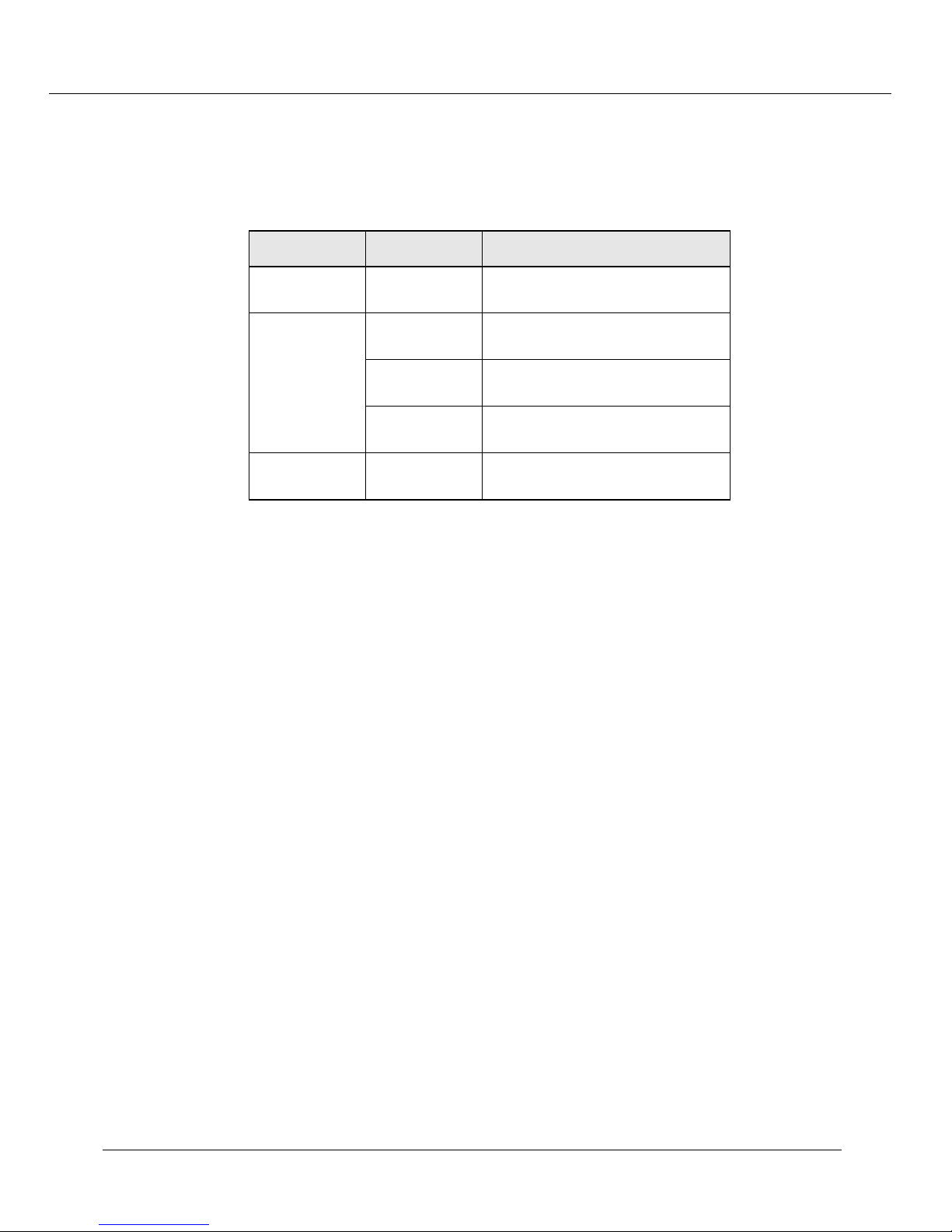
following on properly functioning modules (Table 1-6):
Table 1-6. Power-up LED Function
Module LED Normal Behavior
All Modules Module Status Solid green, indicating normal
operation.
Gigabit
Modules
10/100
Modules
TX and RX Solid green, flashing yellow
Port Solid green, indicating link
HD/FD Solid green, indicating full-duplex
Port Solid green, flashing yellow
Post Power-on Configuration
The system is now fully operational as an 802.1d spanning tree-compliant bridge. All
ports are assigned to a single VLAN (virtual local access network):
All ports can send traffic to all other ports in the system without using a router.
❒
The system is a single flood domain, so all broadcast, multicast, and unknown
❒
unicast traffic will be forwarded to all ports in the system.
intermittently to indicate traffic.
integrity.
operation.
intermittently to indicate traffic.
Cajun P550 Switch Installation Guide 1-11
Page 22

Unpacking and Installing the Cajun P550 Switch
1-12
Cajun P550 Switch Installation Guide
Page 23

2
Configuring the Cajun P550
Switch (Layer 2 & Layer 3)
This chapter and its procedures are common to both Layer 2 and Layer 3 configuration.
Included in this chapter:
❒ Terminal Settings
❒ Configuring the Supervisor Module Using the CLI
❒ Connecting to the Cajun P550 Switch Web Agent
❒ Configuring the Cajun P550 Switch Using the Web Agent
❒ Configuring System Information
❒ Managing Configuration Files
Terminal Settings
To complete initial switch setup, you need a PC with a serial line connection. It must
have the following terminal settings to communicate with the switch (Table 2-1).
Table 2-1. Terminal Settings
Baud Rate Stop Bits Data Bits
9,600 1 8 Xon/Xoff None
Flow
Control
Parity
Configuring the Supervisor Module Using the CLI
To connect to the Web Agent, you must first use the serial command line interface (CLI)
to give the supervisor module an IP address and a subnetwork mask.
To configure the supervisor module using the CLI:
Cajun P550 Switch Installation Guide 2-1
Page 24

Configuring the Cajun P550 Switch (Layer 2 & Layer 3)
1.
Attach a
serial cable
from your PC’s serial port to the serial port of the supervisor
module front panel (refer to Figure 2-1) using a 9-pin straight-through
male-to-female serial cable (refer to “Switch Features,” earlier in this guide for
pinout information).
2.
Run a terminal emulation program (HyperTerminal, for example) on the attached
PC. Ensure that the terminal settings match those listed in Table 2-1.
3.
Power up the switch by turning on the power supplies. In the terminal emulation
program, the switch displays the following startup messages:
Booting the operational system, please wait ....
Initializing the file subsystem ... done
Initializing the event subsystem ... done
Initializing the agent subsystem ... done
Initializing the platform ... done
Initializing the switch subsystem ... done
Starting up threads ...
Periodi c Ta sk
Event
Network Interface
Switch In te rf ac e
Telnet Pr oc es se s
Ping Process
Module Ma na ge r
Address Table Aging
Multica st Pru ni ng
Front Panel Display
Downloa d
Fans Poller
Power Supplies Poller
VTP Snoop in g
Redundant Controller/Element Poller Task
Command Line Parser
Powering up modules
Module 1 Powered
Waiting for power cycle to complete (
Module 2 Po we re d
Initializing the module subsystem ... done
System initialization complete.
Configuring system from Startup Config file [/nvram/startup.txt] ... done
Boot process complete - system is now operational.(3.0->4.0 conversion)
Creating Startup Config file [/nvram/startup.txt] ... done
Copyright © 1999, All rights reserved by Lucent Technologies Corporation
This software is furnished under a license and may be used in accordance
with the terms of such license and with the inclusion of the above
copyright notice. This software or any other copies thereof may
not be provided or otherwise made available to any other person.
No title to and ownership of the software is hereby transferred.
2-2 Cajun P550 Switch Installation Guide
The 17 second power cycle option
)
Page 25

Configuring the Cajun P550 Switch (Layer 2 & Layer 3)
Contains software developed by:
Epilogue Technology Corporation
Copyright (c) 1988 - 1996 Epilogue Technology Corporation
TEC Technically Elite Concepts, Inc.,
Copyright (c) 1994 by Technically Elite Concepts, Inc.,
Hermosa Beach, California, U.S.A.
ISI Integrated Systems, Inc.
Copyright 1991 - 1995, Integrated Systems, Inc.
All other trademarks used herein are the property of their respective
owners.
Lucent Technologies Cajun Switch Agent v4.0.0
Press Ctrl-P for previous command, Ctrl-N for next command,? for help.
Login:
Note:
Information you enter at the Login and Password prompts is case sensitive.
4.
5.
At the
At the
Login
Password:
Password
prompt, enter
prompt, enter
root
. The password prompt displays.
root
as the default password. The command line
interface prompt displays.
6.
Enter the command enable.
7.
Enter the command configure. This changes the command mode to configure
mode so that you can use the setup command.
8.
Enter the command setu p. This initiates a series of queries. Answer each query as
follows:
a.
When prompted to change the super user password, press
default answer of
b.
Enter your
old password
Yes
.
. The system then prompts you for a new password.
Enter
to accept the
The default password is root.
c.
Enter your
new password
, then re-enter the new password to verify your
choice.
d.
Enter the
e.
Enter the
f.
Enter the
Figure 2-1 illustrates an example setup command session.
Cajun P550 Switch Installation Guide 2-3
IP address
subnet mask
for the switch manager’s Ethernet console.
for the network’s IP address.
default gateway
for the switch.
Page 26
Configuring the Cajun P550 Switch (Layer 2 & Layer 3)
Figure 2-1. Layer 2 Setup Command Display
Welcome t o Swi tch S etu p. The br ief s eri es of q ues ti ons t hat
follows w ill h elp y ou to conf ig ure t his swit ch . A ft er co mplet in g
this pr oc ess, you w ill b e abl e to ma nag e the s wit ch us in g:
- the sw itch- bas ed HT TP serv er
- the El ement Ma na gem en t Sys te m.
Text in [ ] is the d efa ul t ans we r f or ea ch qu es tio ns . T o accep t
the def au lt, p res s ENT ER .
Would y ou like to c han ge the su per u ser pass wo rd [Y es] ? Y
Old Passw ord: xxx x
New Passw ord: xxx x
Re-type N ew Pa ssw or d: xx xx
User pa ss word cha ng ed su ccesf ul ly
What do y ou wa nt th e s wi tch m an age r' s c onsol e
Etherne t IP Ad dre ss to b e [0. 0. 0.0 ]? 10 .0.0. 1
What is t he su bne t mas k for y ou r n et wor k's
IP addr es s [0. 0.0 .0 ]? 25 5.255 .2 55. 0
What is t he IP ad dr ess o f the d efa ul t g atewa y for t his n etwor k seg me nt [0.0. 0. 0]?
You can n ow co nne ct to t he sw it ch us ing the fr ont -p ane l
out-of- ba nd 10 Bas e- T c on necti on . T hi s a llows y ou to lo g in
using e it her t he em bed de d web a gen t or the E MS .
See the Inst allation and Opera tion g uide s for ins truc tion o n est ablis hing add ition al IP
network c onnec tio ns .
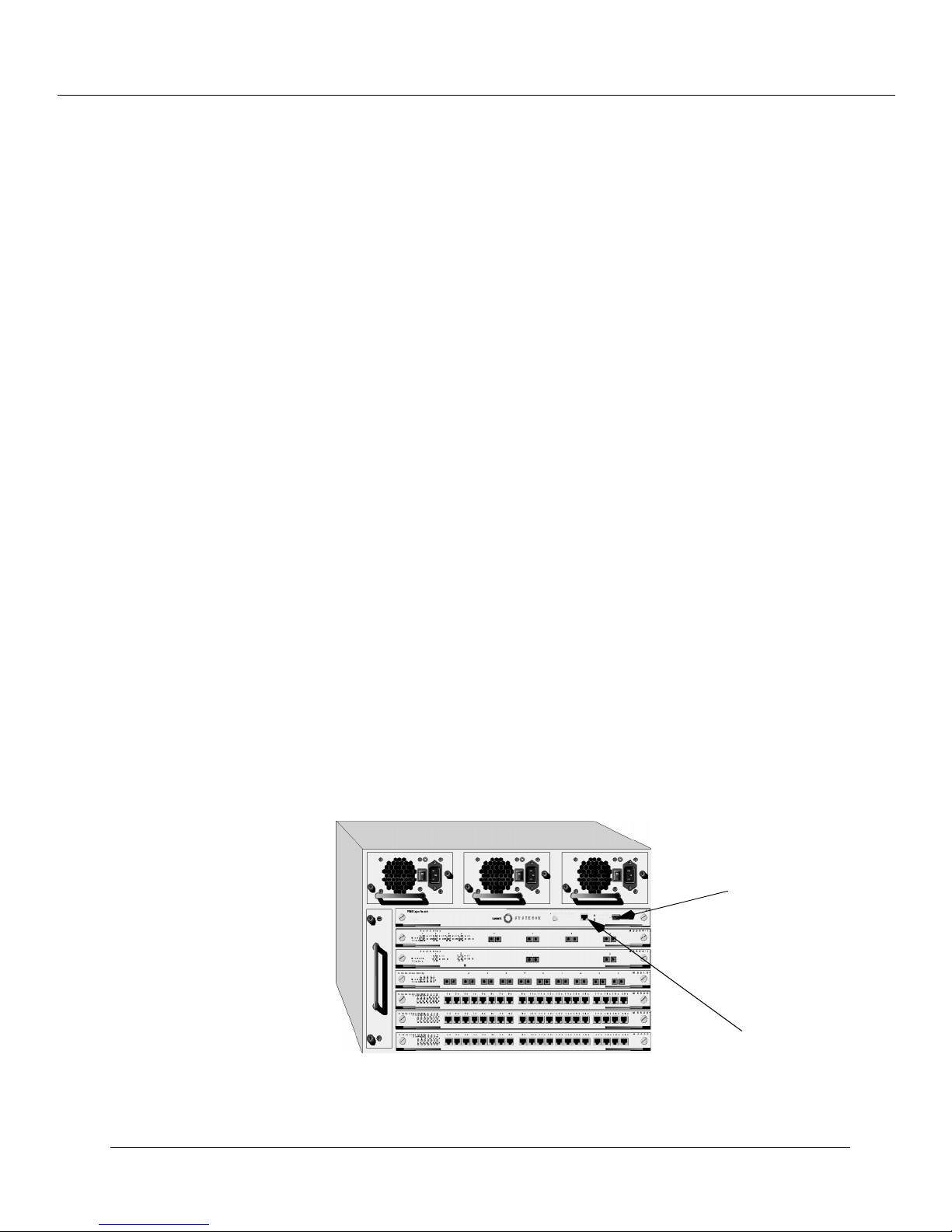
Connect to the system with an out-of-band connection using the 10Base-T port on the
supervisor module front panel for Layer 2 or 10/100Base-T port on the supervisor
module for Layer 3.
Figure 2-2. Cajun P550 Switch
Attach serial
port cable here
2-4 Cajun P550 Switch Installation Guide
Attach
Ethernet cable
here
Page 27
Configuring the Cajun P550 Switch (Layer 2 & Layer 3)
Table 2-2.
Pinouts for 10Base-T Crossover Patch Cables
Pin # Color Pin # Color
1WO3WG
2O 6G
3WG1WO
4B 4B
5WB5WB
6G 2O
7 WBr 7 WBr
8Br8Br
After your switch is connected to the network using an out-of-band connection, log in to
the switch using a Web browser, as described in “Logging In to the Web Agent”, later in
this chapter.
Configuring the Switch Using the Web Agent
The switch includes an embedded HTTP server that allows you to set all the switch’s
parameters. Use this interface for quick and simple configuration changes. Refer to the
Cajun P550 Manager User Guide for information on monitoring and configuring the Cajun
switch using the Cajun P550 Manager interface.
Figure 2-3. Cajun P550 Switch Web Agent Application
Cajun P550 Switch Installation Guide 2-5
Page 28

Configuring the Cajun P550 Switch (Layer 2 & Layer 3)
Logging In to the Web Agent
Although the Web Agent supports any frames-capable browser, the system has been
qualified with the following browsers:
❒
Netscape Navigator 4.5 or later
❒
Microsoft Internet Explorer 3.0 or later
To log in to the Web Agent:
1.
Start your browser.
2.
In the
(for example: http://127.255.255.0). Remember that each interface to the
supervisor module (console or inband) has a separate IP address. For Layer 3, this
location can be that of any of the router interfaces.
3.
Press
4.
Click
5.
Enter a valid
6.
Enter a valid
opens. (Figure 2-3)
Note:
Location
Enter
Login.
Change the root password for the system as soon as possible to optimize
security.
field, enter the
. The login window opens.
The Username/Password dialog box opens.
user name
password
Setting Up User Accounts
User accounts set up in the system allow you to access both the command line interface
and the Web Agent.
URL
of the switch you want to manage
. The default super user name is
. The default password is
root
. The Web Agent window
root
.
To add a user to this interface:
1.
Log in to the switch from your Web browser, using a user name with administrator
privileges. The default login of user
Web Agent application window opens.
2.
In the
Logins
3.
Click
4.
In the
5.
In the
6.
In the
2-6 Cajun P550 Switch Installation Guide
System Configuration
. The User Account Management dialog box opens.
Add User
User Name
Password
Re-enter Password
root
, password
section of the Web Agent window, select
. The Add User Account dialog box opens.
field, enter a
field, enter a
user name
password
field, re-enter the
for the account.
for the account.
root
same password
has this authority. The
User
.
Page 29
Configuring the Cajun P550 Switch (Layer 2 & Layer 3)
7.
From the
Access Type
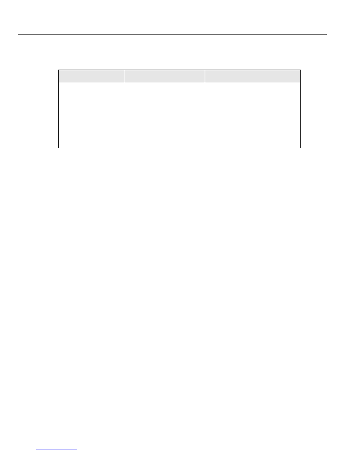
Table 2-3. User Account Access Levels
pull-down menu, select an access type (Table 2-3).
User Level Can Cannot
User (READ_ONLY) View switch configuration
settings and statistics.
Manager
(READ_WRITE)
Administrator
(ADMINISTRATOR)
8.
Click
APPLY
View and set switch
configuration settings, and
view statistics.
View and set all switch
parameters.
save your changes, or
CANCEL
View user accounts and community
strings. Change switch
configurations.
View user accounts and community
strings.
N/A
to restore previous settings.
Configuring Port Parameters Using the Web Agent
The system has two levels of port settings:
❒
Physical port parameters
- Allows you to set up rules that guide the system’s
physical layer interaction (for example, enable/disable, speed, auto-negotiation).
❒
Switch port parameters
- Allows you to specify how the port participates in
switching (for example, VLAN mode, trunking).
The sections that follow explain how to configure these ports.
Configuring Physical Port Parameters on Gigabit Ports
To configure ports on a gigabit module:
1.
In the
& Ports
2.
In the
you want to configure. The Physical Port Configuration dialog box opens.
3.
Click the
the Enable check box if you want to disable the port.
4.
Click
System Configuration
section of the Web Agent window, select
. The Module Information dialog box opens.
Ports
column, click the number (2 or 4 for gigabit modules) for the module
Enable
APPLY
check box to enable a port, or if the check box is enabled, click
to save your settings, or
CANCEL
to restore previous settings.
Modules
5.
In the
Name
Physical Port Configuration dialog box opens.
Cajun P550 Switch Installation Guide 2-7
field, click the
port name
to set additional parameters. The Detailed
Page 30

Configuring the Cajun P550 Switch (Layer 2 & Layer 3)
Refer to Table 2-4 for more information on the Gigabit port parameters.
In the
6.
If this is an end-station port, from the
7.
Port
From the
8.
Name
. For trunk ports, select
field, enter a
port name
Service Port
Flow Control Mode
.
Category
pull-down menu, select
.
pull-down menu, select
Enable
User
to use flow control
to prevent buffer overflows. Disable this feature only when flow control is causing
congestion in other areas of the network.
From the
9.
Pace Priority Mode
pull-down menu, select
Enable
to recognize and
use 3Com’s PACE priority mechanism.
From the
10.
Remote Fault Detect
pull-down menu, select
Enable
to detect remote
link errors.
Notes:
• The remote fault detection functionality should be enabled (on both ends of a
Cajun to Cajun link) in two cases. The first case is when two Cajun gigabit ports
are connected that do not support auto-negotiation. The second case is when a
Cajun gigabit port that does not support auto-negotiation is connected to a
Cajun gigabit port that does support auto-negotiation. If two gigabit ports that
support auto-negotiation are connected, you should enable auto-negotiation.
• Auto-negotiation and remote fault detection cannot be enabled concurrently.
Auto-negotiation must be disabled in order to enable remote fault detection.
When auto-negotiation is enabled, remote fault detection is automatically
disabled.
• For GMAC1 gigabit modules, auto-negotiation is always disabled.
11. Click APPLY to save your changes, or CANCEL to restore previous settings.
Table 2-4 describes the gigabit port parameters:
Table 2-4. Gigabit Port Parameters
Parameter Definition
Name
Category
A user-assigned name for this port (possibly a drop name or the
name of the station or other device connected to the port).
Allows you to select either User Port or Service Port. The User
Port is intended for use with switch connections to end user
nodes. The Service Port is intended for use with switch
connections to servers or other switches.
The primary difference between the User and Service Port
designation is that a Service Port allows the switch to generate
both log messages and alarm messages (traps). The User Port
only generates log messages. This prevents your network
management station from being overwhelmed by port up/down
messages that result from users turning workstations on and off.
2-8 Cajun P550 Switch Installation Guide
Page 31

Tab le 2-4. Gigabit Port Parameters (Continued)
Parameter Definition
Configuring the Cajun P550 Switch (Layer 2 & Layer 3)
Flow Control
Mode
Port PACE Priority
Remote Fault
Detect
Determines if IEEE 802.3z pause control is used on this port.
The pause mechanism allows the port to stop a sending station
from sending more packets if the receiving port’s buffers are full.
This helps prevent lost or dropped packets.
This feature is recommended for use primarily on end station
connections. Using this feature on trunk ports can cause
unnecessary congestion on the network.
Determines if the port detects 3Com’s copyrighted PACE format
as packets pass through the port. PACE allows a packet’s priority
(higher priority packets move through the switch faster) to be
set at the adapter.
Proprietary mechanism to detect remote link errors on Cajun
gigabit ports. The default value is Disabled.
The remote fault detection functionality should be enabled (on
both ends of a Cajun to Cajun link) in two cases:
• When two Cajun gigabit ports are connected that do not
support auto-negotiation.
• When a Cajun gigabit port that does not support
auto-negotiation is connected to a Cajun gigabit port that
does support auto-negotiation.
Configuring Physical Port Parameters on Fast Ethernet Ports
To configure ports on a Fast Ethernet module:
1. In the System Configuration section of the Web Agent window, select Modules
& Ports. The Module Information dialog box opens.
2. In the Ports column, click the number for the module you want to configure (for
example, 12 for 100Base-TX). The Physical Port Configuration dialog box opens.
3. Click Enable to enable a port, or if the check box is enabled, click Enable if you
want to disable the port.
4. Click APPLY to save your changes, or CANCEL to restore previous settings.
5. In the Name field, click the port name to set additional parameters. The Detailed
Physical Port Configuration dialog box opens.
Refer to Table 2-5 for more information on the Fast Ethernet (10/100) parameters.
6. In the Name field, enter a port name.
7. If this is an end-station port, from the Category pull-down menu, select User
Port. For trunk ports, select Service Port.
Cajun P550 Switch Installation Guide 2-9
Page 32

Configuring the Cajun P550 Switch (Layer 2 & Layer 3)
From the
8.
Speed Mode
pull-down menu, select a
speed
(10 Mb/s or 100 Mb/s) if
you want to set the port speed manually. If you set the port to auto-negotiate, this
setting is ignored. (This feature is only available for 10/10 TX).
From the
9.
Duplex Mode
pull-down menu, select a
mode
(Half-duplex or
Full-duplex) if you want to set the port’s duplex mode manually. If you set the port
to auto-negotiate, this setting is ignored.
From the
10.
Flow Control Mode
pull-down menu, select
Enable
if you want this
port to use Flow Control to prevent buffer overflows. Disable this feature only
when flow control is causing congestion in other areas of the network.
From the
11.
Auto Negotiation Mode
pull-down menu, select
Enable
. (This feature
is only available for 10/10 TX).
Note:
This feature works best when the port or device on the other end of the
connection auto-negotiates as well. If you are having problems with
auto-negotiating connections, try setting the modes manually using the
command line interface. For example,
From the
12.
Auto Negotiation Speed Advertisement
Duplex Advertisement
Advertisement
pull-down menus, set
, respectively. The switch sends these values to the device on the
set port auto 7/3 enable
and
Auto Negotiation
Speed
and
Duplex
other end of the connection at the start of the auto-negotiating process. In general,
the defaults are best, but there may be situations when you want to fix one setting,
but allow the other setting to auto-negotiate. (This feature is only available for
10/10 TX).
.
From the
13.
Rate Limit Mode
pull-down menu, select
Enable
if you want this port
to limit the number of unknown unicast and multicast (flooded) packets it tries to
forward.
From the
a.
Rate Limit Rate
pull-down menu, select the
percentage
of a port’s
traffic that can be unknown unicast and broadcast packets. Lower this value if
the port is having overflow problems.
From the
b.
Rate Limit Burst Size
pull-down menu, select a
packet limit
the number of packets allowed in a single burst. Valid values are 1 to 2048. For
Fast Ethernet ports, set this value lower than 1024 (the output buffer’s
capacity). Set this value lower if the port is experiencing overflow problems.
From the
14.
Pace Priority Mode
pull-down menu, select
Enable
if you want this
port to recognize and use 3Com’s PACE priority mechanism.
15.
Click
APPLY to
save your changes, or
CANCEL
to restore previous settings.
for
2-10 Cajun P550 Switch Installation Guide
Page 33

Configuring the Cajun P550 Switch (Layer 2 & Layer 3)
Table 2-5 describes the Fast Ethernet port parameters:
Tab le 2-5. Fast Ethernet (10/100) Port Parameters
Parameter Definition
Name A user-assigned name for this port (possibly a drop name or the
name of the station or other device connected to the port).
Category Allows you to select either User Port or Service Port.
• The User Port is intended for use with switch connections to
end user nodes.
• The Service Port is intended for use with switch connections
to servers or other switches. The Service Port allows the
switch to generate both log messages and alarm messages
(traps). The User Port only generates log messages,
preventing your network management station from being
overwhelmed by port up/down messages that result from
users turning workstations on and off.
Speed Mode Allows you to select the speed of the port manually (to either 10
or 100 Mb/s). If auto-negotiation is enabled, this setting is
ignored.
Duplex Mode Allows you set the port duplex mode (half- or full-duplex). If
auto-negotiation is enabled, this setting is ignored.
Flow Control Mode Determines if flow control is used on this port. For half-duplex
links, active backpressure jams the sending Ethernet channel
until the port’s buffers can receive more packets. This prevents
lost or dropped packets.
For full-duplex links, IEEE 802.3z pause control allows the port
to stop a sending station from sending more packets if the
receiving port’s buffers are full.
For TX and FX ports, there is an additional option for Enable
with Aggressive Backoff. This option limits the size of the bursts.
Flow Control is recommended for use primarily on end-station
connections. Using this flow control on trunk ports can cause
unnecessary congestion on the network.
Auto Negotiation
Mode
Allows you to set the port to auto-negotiate a speed and duplex
mode. Auto-negotiate works best when the connection on the
other end of the link is set to auto-negotiate as well. If you set a
port to auto-negotiate, and the connection is not successful, set
the port speed and duplex mode manually.
Auto Negotiation
Speed/Duplex
Advertisement
Determines what information the port advertises when it starts
auto-negotiating. In most cases, 10/100 and Half/Full are the
best settings, but there may be cases when you want to
auto-negotiate one parameter, while keeping the other fixed.
Cajun P550 Switch Installation Guide 2-11
Page 34
Configuring the Cajun P550 Switch (Layer 2 & Layer 3)
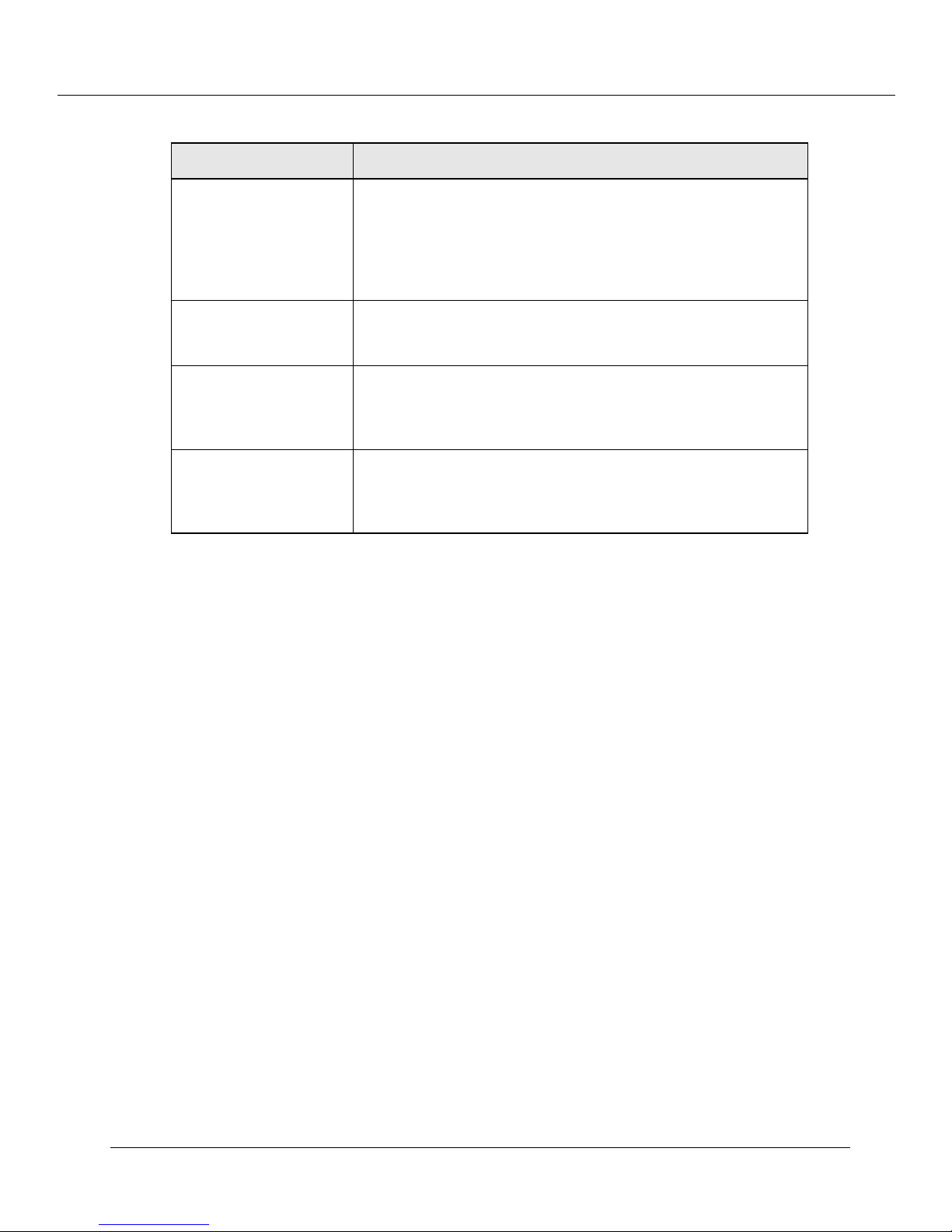
Table 2-5. Fast Ethernet (10/100) Port Parameters (Continued)
Parameter Definition
Rate Limit Mode
Rate Limit Rate
Rate Limit Burst Size
Port PACE Priority
Prevents the switch from overwhelming the output buffer on
lower-speed ports by placing a threshold on the percentage of
port traffic that can be flooded packets (unknown unicasts and
multicasts). You can optionally include known multicast packets
in this percentage to further decrease the possibility of the port’s
output buffer being overwhelmed.
Determines the percentage of a port’s forwarded traffic that can
be unknown unicast and multicast (flooded). Lower this value if
the port has overflow problems.
Determines the limit of packets allowed in a single burst.
Accepted values are 1 to 2048. For Fast Ethernet ports, set this
value lower than 1024 (output buffer capacity). Lower this
value if the port has overflow problems.
Determines if the port detects 3Com’s proprietary PACE format
as packets pass through the port. PACE allows a packet’s priority
(higher priority packets move through the switch before lower
priority packets) to be set at the adapter.
Using the All Ports Configuration Dialog Box
The All Ports Configuration dialog box allows you to apply the same parameter settings
to all switch ports for P220 switches and in a module for the P550 using a single
command.
To set all ports in a module:
1. In the System Configuration section of the Web Agent window, select Modules
& Ports. The Module Information dialog box opens.
2. In the Ports column, click the number for the module you want to configure (for
example, 10 for 100Base-FX). The Port Configuration dialog box opens.
3. Click All Module Switch Ports Configuration. The All Ports Configuration
dialog box opens.
4. Set port parameters as described beginning in “Configuring Physical Port
Parameters on Gigabit Ports” and/or “Configuring Physical Port Parameters on Fast
Ethernet Ports”, earlier in this chapter.
5. Click APPLY to save your changes, or CANCEL to restore previous settings.
2-12 Cajun P550 Switch Installation Guide
Page 35
Viewing Switch Port Parameters
To view switch port parameters:
Configuring the Cajun P550 Switch (Layer 2 & Layer 3)
In the
1.
2.
& Ports
In the
System Configuration
. The Module Information dialog box opens.
Switch Ports
column, click the
the desired module. The Switch Ports dialog box opens.
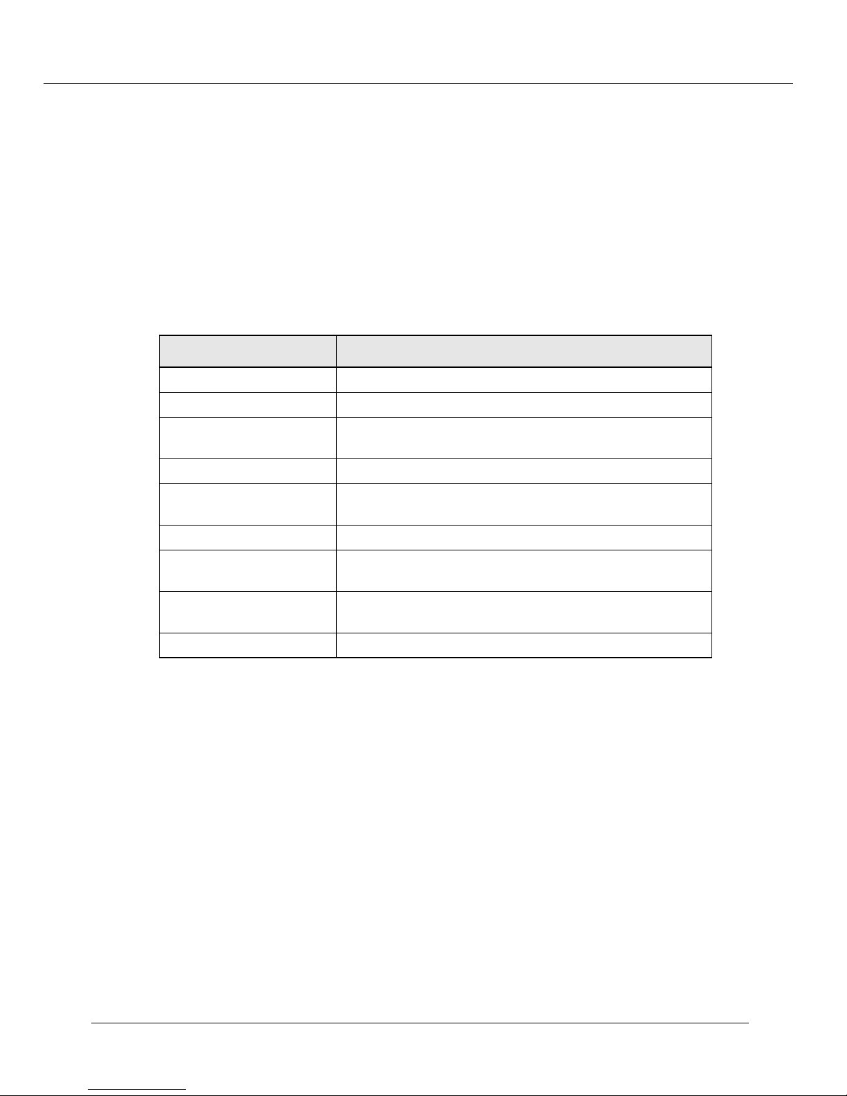
Use Table 2-6 for more information on switch port parameters:
3.
Table 2-6. Switch Port Parameters
Parameter Definition
Links
Port
Name
Port VLAN
VLAN Classification
Trunk Mode
Hunt Group
Opens associated dialog boxes.
Displays the port associated with the selected module.
Displays the port name and opens the Switch Port
Configuration dialog box for the selected module.
Displays the port VLAN for the selected module.
Displays the port VLAN classification for the selected
module.
Displays the port’s trunk mode for the selected module.
Displays the hunt group of which the port is a member for
the selected module.
section of the Web Agent window, select
number
for switch port information about
Modules
STAP Mode
MAC Address
Click one of the following for more information on switch ports:
4.
•
Next/Previous Module
Displays whether the spanning tree algorithm protocol is
enabled or disabled for the selected module.
Displays the port’s MAC address for the selected module.
- to view the next or previous module’s switch port
parameters.
•
Modules
•
All Module Switch Ports Configuration
- to return to the Module Information dialog box.
Configuration All Ports dialog box and configure all ports for the selected
module.
Configuring Switch Port Parameters
Switch port parameters set how each port performs switching functions (for example,
VLAN parameters, hunt group assignments, trunk mode, and frame tag scheme). Refer
to Table 2-7 for more information on individual switch port configuration parameters.
- to open the Switch Port
Cajun P550 Switch Installation Guide 2-13
Page 36
Configuring the Cajun P550 Switch (Layer 2 & Layer 3)
To configure switch port parameters:
In the
1.
& Ports
From the
2.
System Configuration
. The Module Information dialog box opens.
Model Number
configure ports. Click the
section of the Web Agent window, select
column, locate the
Switch Ports
Switch Ports dialog box opens.
3.
In the
Name
column, click the name for the port you want to configure. The
Switch Port Configuration dialog box opens.
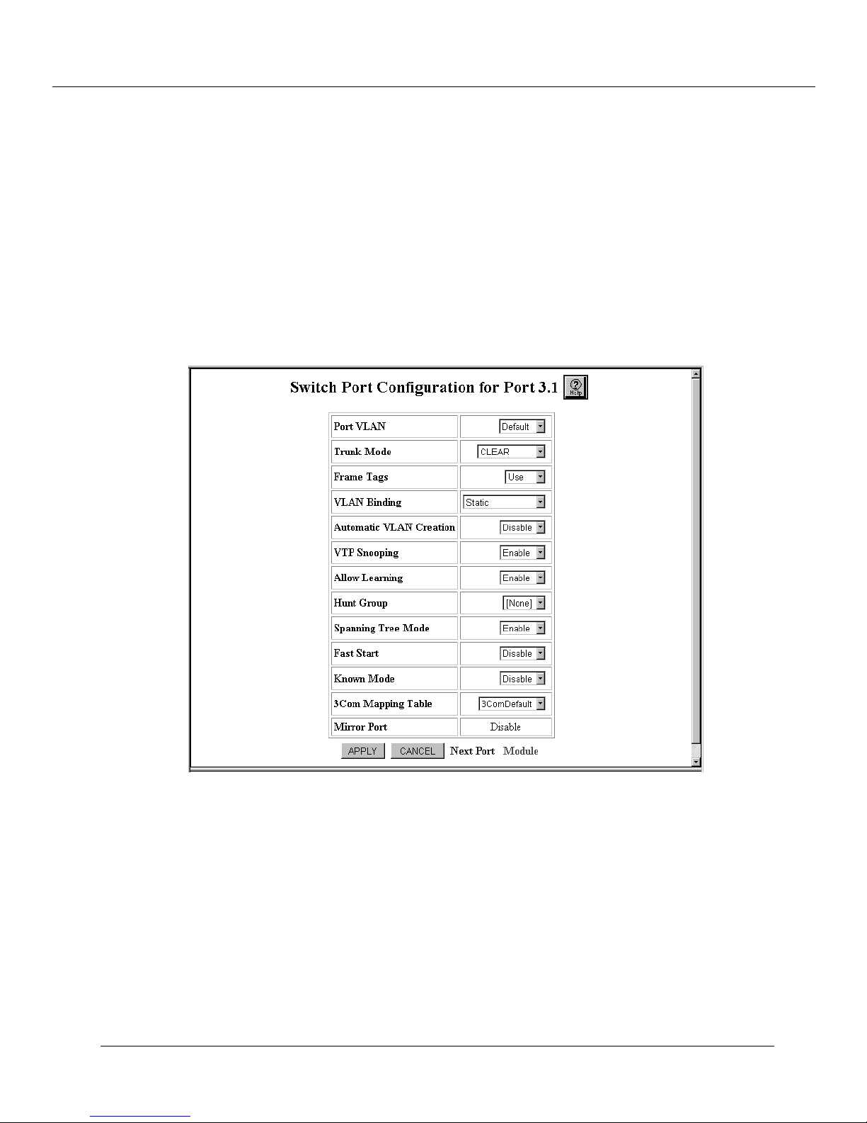
Figure 2-4. Switch Port Configuration Dialog Box
Modules
module
for which you want to
column next to the selected module. The
Refer to “Configuring Port VLAN Parameters” and “Configuring Non-VLAN Switch
Port Parameters”, later in this chapter, for your specific configuration needs.
2-14 Cajun P550 Switch Installation Guide
Page 37

Configuring the Cajun P550 Switch (Layer 2 & Layer 3)
Table 2-7 describes Switch Port configuration parameters:
Table 2-7.
Switch Port Configuration Parameters
Parameter Definition
Port VLAN
Trunk Mode
Specifies the VLAN assignment for this port.
Select the trunk mode.Allows you to define
the port as a trunk and allows you to select
the appropriate VLAN trunking format if the
port is connected to another switch. Refer to
Table 2-8 for more information on trunk
mode options.
Frame Tags
Select whether to ignore or use received
Frame VLAN tags. If you ignore VLAN tags
on incoming frames, the frames are bound to
the port’s default VLAN. The default value is
Use.
VLAN Binding
Select the port’s outgoing VLAN binding
type. Refer to Table 2-9 for more information
on VLAN binding options.
Automatic VLAN
Creation
Select to enable or disable the ability to
automatically create a VLAN each time the
port receives a frame from an unknown
VLAN. The default value is Disable.
VTP Snooping
Select to enable or disable VTP Snooping on
this port. The default value is Disable.
Allow Learning Select to enable or disable the port’s learning
of new addresses. The default value is
Enable.
Hunt Group Select a hunt group for which this port will
be a member. The default value is None.
Spanning Tree Mode Select to enable or disable spanning tree
protocol on this port. The default value is
Enable.
Note:
For the Cajun P220 switch, you
will be unable to modify this
feature on the CPU switch port.
Fast Start Select to enable or disable fast start on this
port. The default value is Disable.
Note:
For the Cajun P220 switch, you
will be unable to modify this
feature on the CPU switch port.
Cajun P550 Switch Installation Guide 2-15
Page 38
Configuring the Cajun P550 Switch (Layer 2 & Layer 3)
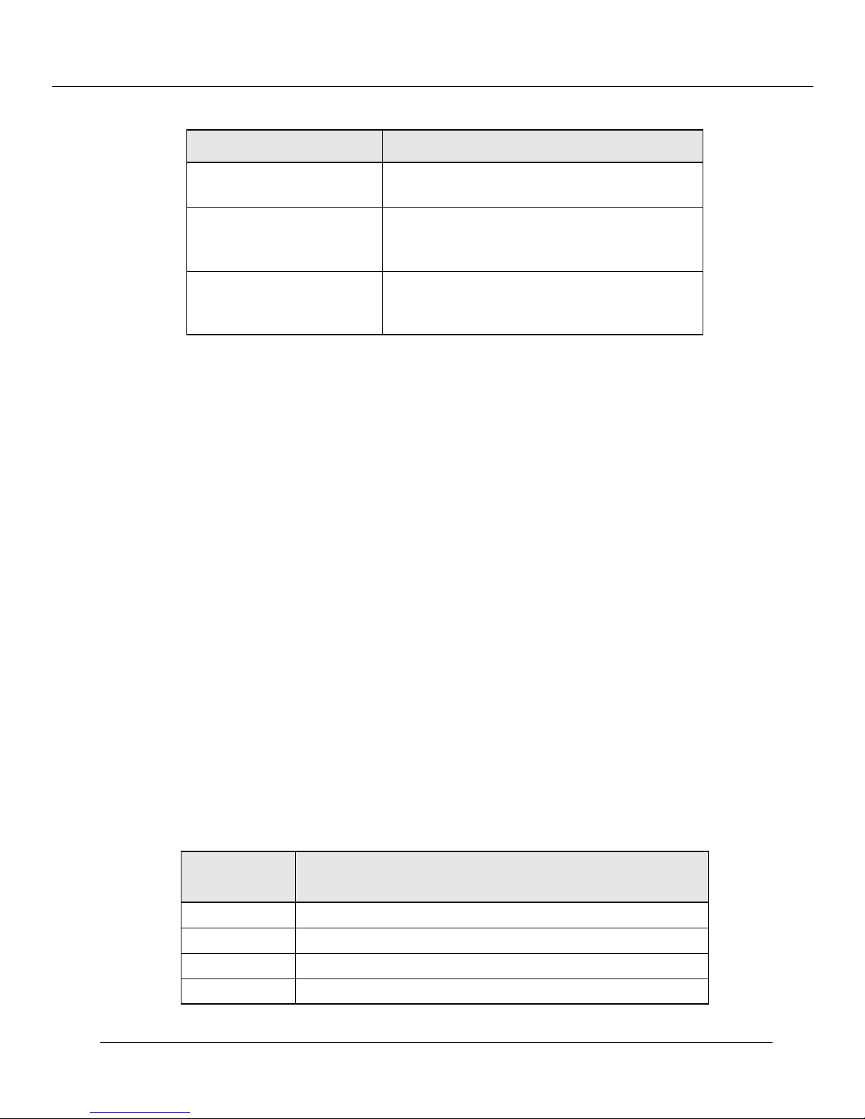
Table 2-7. Switch Port Configuration Parameters (Continued)
Parameter Definition
Known Mode Select to enable or disable known mode. The
default value is Disable.
3Com Mapping Table Select how incoming tagged frames from
3Com equipment are mapped to Lucent
VLANs. The default is 3ComDefault.
Mirror Port Displays whether the mirror port is enabled
or disabled. This is a Fast Ethernet only
option.
Configuring Port VLAN Parameters
Port VLAN parameters determine how a particular port’s traffic is flooded to VLANs
when tagged and untagged packets are received on the port. See the examples later in
this section for recommendations on settings for particular trunk port connections.
Refer to “VLAN Operation”, in the Cajun P550/P220 Switch Operation Guide, for more
information on creating VLANs.
Refer to “Viewing Switch Port Parameters”, earlier in this chapter, for information on
accessing the Switch Port dialog box.
To configure port VLAN parameters:
1. From the Port VLAN pull-down menu in the Switch Port Configuration for Port
XX dialog box, select a VLAN as the VLAN assignment for this port. This causes all
untagged frames arriving on this port to be assigned to the specified VLAN. The
port will still assign incoming tagged packets to the VLAN indicated by the tag.
2. From the Trunk Mode pull-down menu, select the option (excluding Clear) to
indicate that the port is a trunk and to select the appropriate VLAN trunking format
if the port is connected to another switch.
Table 2-8. describes the VLAN Trunking Mode options:
Table 2-8. VLAN Trunking Mode Options
VLAN Mode
Applies the following format to packets entering
this port:
Clear No VLAN tag. This is the default setting.
IEEE-802.1Q The IEEE 802.1Q Ethernet VLAN tagging scheme.
Multi-layer A widely available proprietary VLAN tagging scheme.
3Com 3Com’s VLAN tagging scheme.
2-16 Cajun P550 Switch Installation Guide
Page 39

Configuring the Cajun P550 Switch (Layer 2 & Layer 3)
From the
3.
Frame Tags pull-down menu, select whether you want to Ignore or
Use received Frame VLAN tags. If you ignore VLAN tags on incoming frames, the
frames are bound to the port’s default VLAN.
4. From the VLAN Binding pull-down menu, select a VLAN binding type for this
port.
Table 2-9 describes the VLAN Binding Options.
Table 2-9. VLAN Binding Options
Option Definition
Static
Bind to All
Assigns VLAN membership manually, using the VLAN Switch
Ports page described in “Creating and Implementing VLANs”, in
the
Cajun P550/P220 Switch Operation Guide
Binds this port to all VLANs known to the switch. This is an
appropriate mode for switch-to-switch connections.
If you use 3Com Mapping Tables, this setting is ignored.
.
Note: When a tagged IEEE 802.1Q packet arrives on a
port that is set to bind to all and the VLAN does
not exist on the switch, the packet is forwarded
on to the VLAN assigned to the port default
VLAN for that port. To prevent unintended
forwarding of unknown VLAN traffic to the
port’s default VLAN, configure the port default
VLAN to Discard. The automatic VLAN creation
feature will not work if the port’s default VLAN
is the discard VLAN, because the switch does not
learn for this VLAN.
Bind to Received Binds this port to any VLAN it receives traffic from.
Note:
If Automatic VLAN Creation is enabled, the port
binds to previously unknown VLANs, and a
VLAN entry is added to the switch VLAN table. If
Automatic VLAN Creation is disabled, the port
does not bind to any VLAN unknown to the
switch.
5. From the Automatic VLAN Creation pull-down menu, select Enable to
automatically create a VLAN each time the port receives a frame from an unknown
VLAN.
Note: This feature does not create entries in 3Com Mapping Tables. Refer to
“Creating 3Com Mapping Tables”, in Chapter 12, for more information on
3Com Mapping Tables.
6. Click APPLY to save your changes, or CANCEL to restore previous settings.
Cajun P550 Switch Installation Guide 2-17
Page 40

Configuring the Cajun P550 Switch (Layer 2 & Layer 3)
Configuring VTP Snooping
VTP is a Layer 2 protocol developed by Cisco to maintain VLAN configuration
consistency among its switches. this protocol only runs over trunk ports that have
enabled either Cisco ISL or IEEE 802.1Q tagging. VTP Snooping allows a Cajun switch to
synchronize its VLAN configuration with that of a Cisco switch running VTP in the same
network. VLAN additions, deletions, and name changes made on the network’s Cisco
VTP server will be automatically updated on Cajun switches that have VTP Snooping
enabled and have connectivity to the Cisco VTP server. VLAN changes made on a Cajun
switch are not automatically updated on any other switch.
Note:
VTP Snooping is enabled by default. You would only need to change VTP
Snooping port settings if you wanted to disable its ability to learn VLAN
changes on the network’s Cisco VTP server.
To configure switch port VTP Snooping parameters:
1.
2.
In the
Ports
In the
System Configuration
. The Module Information dialog box opens.
Switch Ports
column, click on the
section of the Web Agent, click
Switch Ports link
Modules and
for the module
which you want to enable VTP snooping. The Switch Ports dialog box for that
module opens.
3.
In the
Name
column, click the
on which you want to enable VTP Snooping
port
switch wide. The Switch Port Configuration dialog box opens for that port.
From the
4.
Multi-layer
Trunk Mode
to match the trunk mode setting of the switch port of the switch port
pull-down menu, select either
IEEE 802.1Q
at the other end of the link.
From the
5.
VTP Snooping
pull-down menu, select
Enable
. This is disabled by
default.
6.
Click
APPLY
to save your changes, or
CANCEL
to restore previous settings.
or
In the
7.
Snooping
2-18 Cajun P550 Switch Installation Guide
Switching Parameters
. The VTP Snooping Configuration dialog box opens.
section of the Web Agent window, click
VTP
Page 41
Configuring the Cajun P550 Switch (Layer 2 & Layer 3)
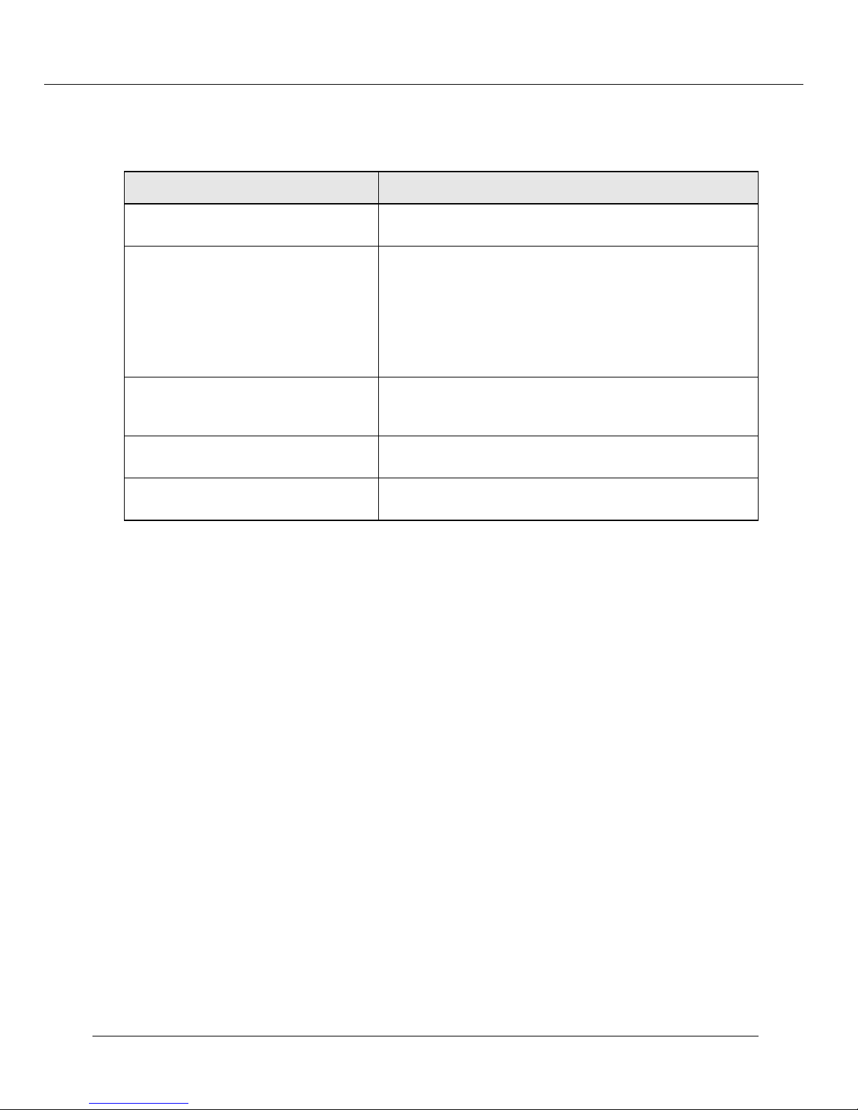
Use Table 2-10 to configure your switch VTP Snooping parameters.
8.
Table 2-10. VTP Snooping Parameters
Parameter Definition
VTP Snooping State Select to enable or disable the VTP snooping protocol
globally for the switch. The default value is Disabled.
Domain Name Enter the name associated with the Cisco VTP domain. The
default is Null.
Note:
Configuration Revision Number Displays the VTP snooping configuration revision number
associated with the last successful VTP configuration
update on the Cajun switch.
Updater Identity Displays the IP address of the Cisco switch that initiated the
configuration update.
The domain name is automatically learned
within approximately five minutes from a
Cisco VTP switch provided both the Domain
Name is Null and the VTP Snooping State is
enabled on the Cajun switch.
Update Timestamp Displays the date and time that the Cisco switch initiated
the configuration update.
9.
Click
APPLY
to save your changes, or
CANCEL
to restore previous settings.
Configuring Non-VLAN Switch Port Parameters
To configure Non-VLAN switch port parameters:
In the
1.
pull-down menu, select
Switch Port Configuration
Disable
feature can be useful for security. Selecting Enable allows the port to learn new
addresses.
For example, you can set this parameter to Disable, then add a static MAC address
entry for this port.
From the
2.
Hunt Group
pull-down menu, select a
will be a member. Refer to “Using Hunt Groups to Aggregate Bandwidth between
Switches”, in
the Cajun P550/P220 Switch Operation Guide
groups.
dialog box, from the
Allow Learning
to stop the port’s learning of new addresses. This
hunt group
for which this port
, for more information on hunt
From the
3.
Spanning Tree
tree protocol on this port.
Cajun P550 Switch Installation Guide 2-19
pull-down menu, select to
Enable
or
Disable
spanning
Page 42
Configuring the Cajun P550 Switch (Layer 2 & Layer 3)
From the
4.
Fast Start
pull-down menu, select to
Enable or Disable
. When
enabled, Fast Start mode ports begin forwarding traffic without waiting for the
spanning tree negotiation to complete. Fast start eliminates the waiting time of
listen and learn states. Ports immediately enter the forward state.
From the
5.
Known Mode
pull-down menu, select to
Enable or Disable.
Selecting
Enable suppresses the packets with unknown unicast destination addresses flooded
to this port. For example, if a known end-station or file server is connected to the
port, there’s no need to flood unknown unicasts to that port. You must manually
enter a static MAC address for the station actually attached to the port.
From the
6.
3Com Mapping Table
pull-down menu, select an
assignment
to
specify how incoming tagged frames from 3Com equipment are mapped to Lucent
VLANs. Refer to “Creating 3Com Mapping Tables”, in
Operation Guide
, for more information on 3Com Mapping Tables.
the
Cajun P550/P220 Switch
7. Click APPLY to save your changes, or CANCEL to restore previous settings.
Examples of Switch Ports Settings for Various VLAN Connection Types
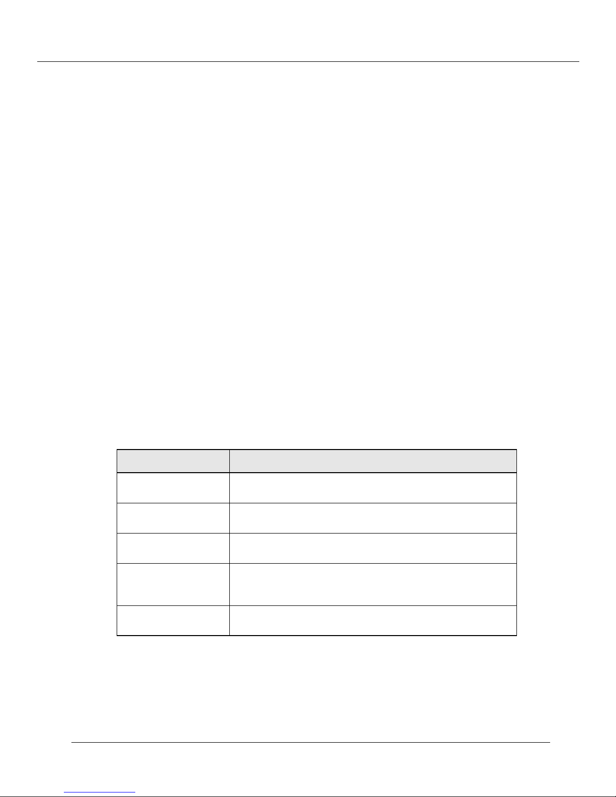
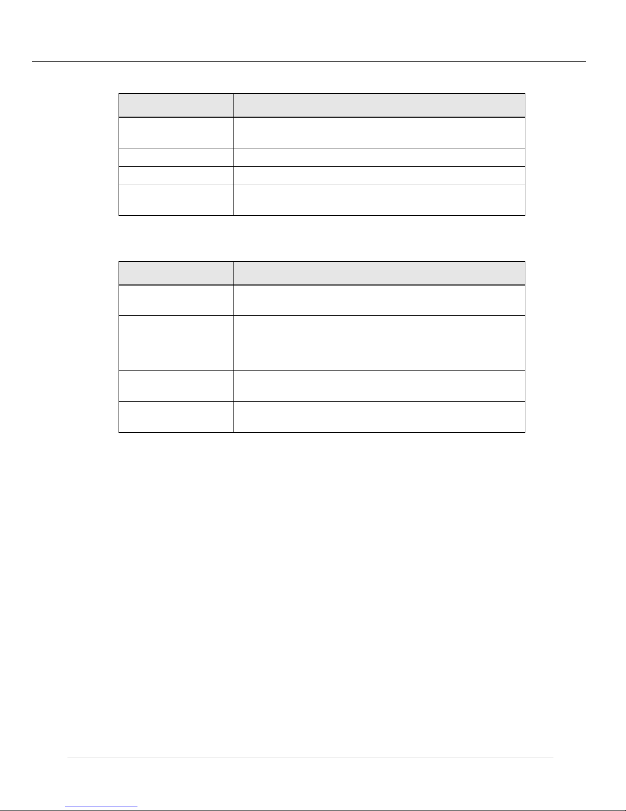
Use Table 2-11 through Table 2-13 for recommended switch port settings for each
connection type.
Note: Automatic VLAN Creation and VTP Snooping must not be enabled at the
same time.
Table 2-11. Example 1. Trunk to Cisco Catalyst 5000
TM
Parameter Recommended Setting
Port VLAN Default - causes untagged packets to be assigned to the
default VLAN.
Trunk Mode Multi-layer- causes the port to send frames using the
multi-layer format.
VLAN Binding Bind to All - binds the port to all VLANs known to the
switch.
Automatic VLAN
Creation
VTP Snooping Enable - cause the switch to update its VLANs as they are
Enable (Disable if using VTP Snooping) - causes the
switch to learn new VLAN IDs that arrive at the port, and then
bind the port to these VLANs.
created, deleted, or changed on the Catalyst.
2-20 Cajun P550 Switch Installation Guide
Page 43
Configuring the Cajun P550 Switch (Layer 2 & Layer 3)
Table 2-12. Example 2. Trunk to 3Com SuperStack
TM
Parameter Recommended Setting
Port VLAN Default - This parameter is ignored when using 3Com
VLANs.
Trunk Mode 3Com - Allows the switch to read the incoming VLAN tags.
VLAN Binding Static - This parameter is ignored when using 3Com VLANs.
Automatic VLAN
Creation
Table 2-13. Example 3. Trunk to Bay Networks System 5000
Disable - This parameter is ignored when using 3Com VLANs.
TM
Parameter Recommended Setting
Port VLAN Default - Causes untagged packets to be assigned to the
default VLAN.
Trunk Mode IEEE-802.1Q - Causes the port to send frames using the
IEEE-802.1Q format. This assumes that you have configured
the Bay Networks switch to use IEEE-802.1Q VLAN tagging as
well.
VLAN Binding Bind to All - Binds the port to all VLANs known to the
switch.
Automatic VLAN
Creation
Enable - Causes the switch to learn new VLAN IDs that arrive
at the port, and then bind the port to these VLANs.
Configuring Fast Start Mode
Fast Start mode causes ports to begin forwarding traffic without waiting for the spanning
tree negotiation to complete.
Examples of situations where you may want to set a port to Fast Start mode are:
❒
End-station ports that do not need to participate in the full spanning tree
negotiation
❒
Loop-free topologies that do not need spanning tree protocol to resolve redundant
connections
To enable Fast Start for ports on a module associated with a selected bridge:
In the
1.
& Ports
System Configuration
. The Module Information dialog box opens.
section of the Web Agent window, click
Modules
In the
2.
Switch Ports
selected module. The Switch Ports dialog box opens.
Cajun P550 Switch Installation Guide 2-21
column, click on the
switch port number
listed for the
Page 44

Configuring the Cajun P550 Switch (Layer 2 & Layer 3)
To set Fast Start mode on individual ports, in the
3.
name
for the selected module. The Switch Port Configuration dialog box opens.
Name
Or
To set Fast Start mode on all ports in a module, click
Configuration
From the
4.
. The Switch Port Configuration on All Ports dialog box opens.
Fast Start
pull-down menu, select
Enable
the selected module ports.
5.
Click
APPLY
to save your changes, or
CANCEL
to clear your selection.
Using the All Ports Configuration Dialog Box
The All Ports Configuration dialog box allows you to apply the same parameter settings
to all switch ports in a module using a single command.
To set all switch ports in a module using a single command:
In the
1.
2.
& Ports
In the
System Configuration
. The Module Information dialog box opens.
column, click the
Ports
configure (for example, 10 for 100Base-FX). The Physical Port Configuration dialog
box opens.
section of the Web Agent window, select
number
of ports listed for the module you want to
column, click the
port
All Module Switch Port
to enable Fast Start mode on
Modules
3.
Click
All Module Ports Configuration
at the bottom of the dialog box. The All
Ports Configuration dialog box opens.
Select the port on which you want your changes to occur.
4.
Set port parameters for the selected ports, as described in “Viewing Switch Port
5.
Parameters”, earlier in this chapter.
6.
Click
APPLY
to save your changes, or
CANCEL
to restore previous settings.
2-22 Cajun P550 Switch Installation Guide
Page 45
Setting Up SNMP Communities
SNMP communities are the SNMP values that an SNMP manager uses to manage the
switch. SNMP Version 2c is supported.
Table 2-14. SNMP Communities Parameters
Parameter Definition
Configuring the Cajun P550 Switch (Layer 2 & Layer 3)
Community String
This string serves as a password that you enter at the
network management station. It provides the level of
access to the switch that you specify on this page.
IP Address
Allows you
to send SNMP responses only to a station
with any or a particular IP address.
Access
Helps provide security when you use SNMP to
manage the network from a single workstation. Refer
to Table 2-15 for more information on Access options.
The default value is Read-Write.
Security Level Allows you to select the security level for this
community string. Refer to Table 2-16 for more
information on security level options. The default
value is Normal.
Trap Receiver Allows you to enable or disable the transmission of
traps to the selected IP address. The default value is
Disable.
To set SNMP communities:
In the
1.
System Configuration
Administration
. The SNMP Community Management dialog box opens.
section of the Web Agent window, select
SNMP
Click
2.
3.
4.
CREATE
In the
Community String
From the
IP Address
and enter an
Cajun P550 Switch Installation Guide 2-23
. The Create SNMP Community dialog box opens.
pull-down menu, select
IP Address
field, enter a
in the appropriate fields.
community name
for any IP address or
Any
.
Specific
Page 46
Configuring the Cajun P550 Switch (Layer 2 & Layer 3)
5. From the Access pull-down menu, select a level for this community (Table 2-15).
Table 2-15. Access Levels
Access Level Manager Can... Manager Cannot...
Read-Only View switch configuration settings
and statistics.
Read-Write View and set switch configuration
settings, and view statistics.
Read-Write with
Security Level Set
to admin
None Do nothing. This selection allows
View and set all switch parameters,
including community table.
you to disable a string without
deleting it.
View community strings.
Change switch
configurations.
View community strings.
N/A
Access any switch
features.
6. From the Security Level pull-down menu, select a security level for this
community string (Table 2-16).
Table 2-16. SNMP Security Levels
Option Allows Access to...
normal All switch configuration and reporting functions.
admin All switch configuration and reporting functions, including
access to community configuration.
7. From the Trap Receiver pull-down menu, select Enable.
8. Click APPLY to save your changes, or CANCEL to restore previous settings.
Changing the Console Serial Port Settings
You can use the Web Agent to change the communications settings for the serial port
connection on the front panel of the Layer 3 supervisor module.
Initially, the switch’s console port is configured as a TTY Console to support a TTY
connection. The Layer 2 and Layer 3 supervisor modules allow you to reconfigure the
console serial port as a PPP Console to support a dial-in PPP connection using a modem.
Note: As a PPP console, you can change only the switch’s baud rate and flow control
parameters. The flow control parameters are limited to None or Xon/Xoff.
2-24 Cajun P550 Switch Installation Guide
Page 47
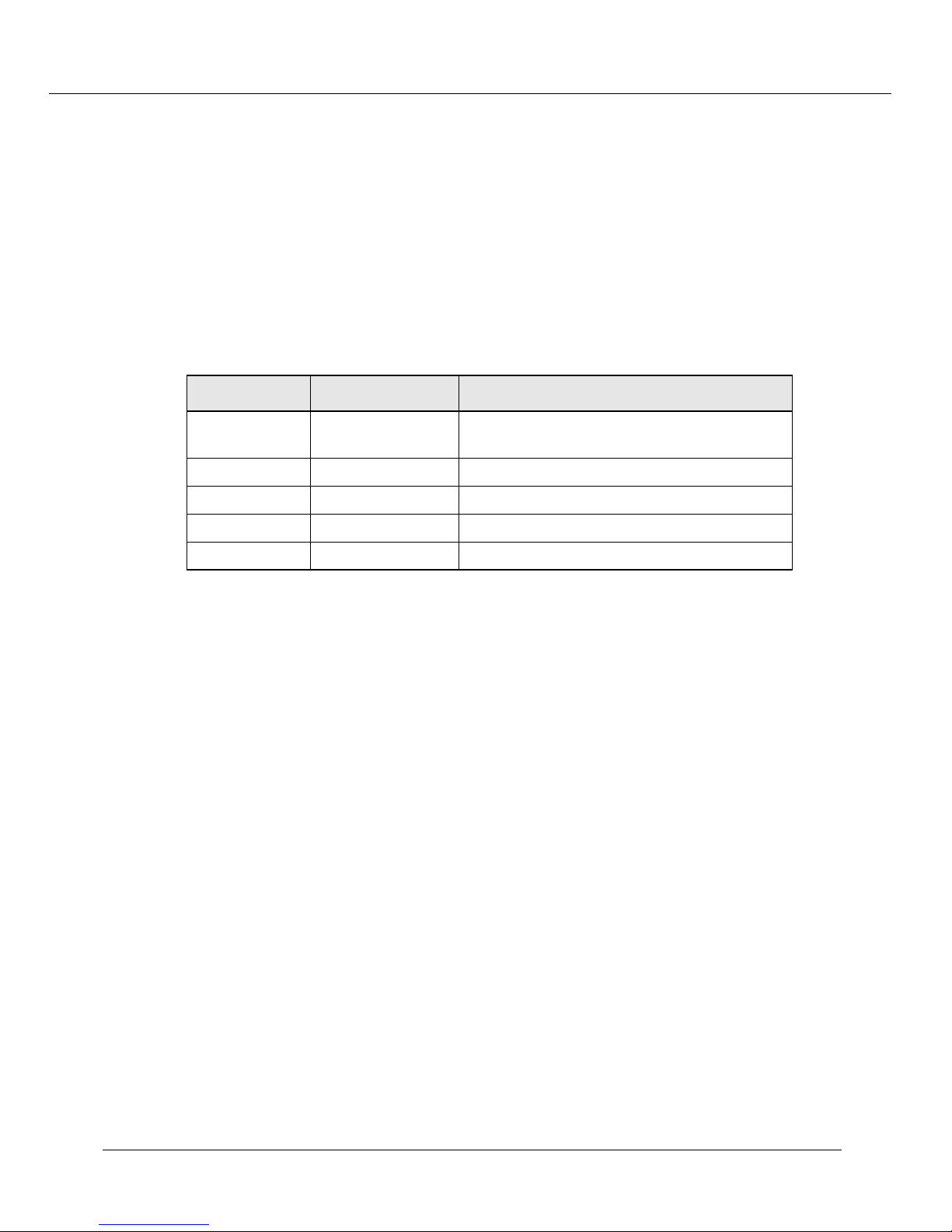
Configuring the Cajun P550 Switch (Layer 2 & Layer 3)
Configuring the Serial Console Port as a TTY Console
To configure the console serial port as a TTY Console:
1. In the System Configuration section of the Web Agent window, select Console
Configuration. The Console Configuration dialog box opens.
2. Click TTY for your console type and click SELECT. The Console Port
Configuration dialog box opens.
3. Use Table 2-17 to set your console serial port settings:
Table 2-17. Console Serial Port Options
Option Default Available Settings
Baud Rate 9600 300, 1200, 2400, 4800, 9600, 19200, 38400,
57600, 115200
Flow Control Xon/Xoff (TTY) None, Xon/Xoff (TTY)
Data Bits 87 or 8
Parity None Odd, Even, or None
Stop Bits 1 1 or 2
4. Click APPLY to save your changes, or CANCEL to restore previous settings.
Connecting a Modem
In order to use the serial console port as a PPP console, you must connect a modem to
the switch. When you use the specified serial cable and connectors, the switch will
convert the normal DCE interface to a DTE interface that is used by modems.
When the switch is configured for PPP mode, it will periodically send the modem config
string from the serial console port. This will synchronize the baud rates between the
modem and the console port and configure the modem to operate with the switch’s DTE
interface.
The switch does not use any output signals except for TXD. It uses the DTR (converted to
DSR by the specified cable and connectors) input connected to the modem DCD output,
to detect that the modem is connected. It supports XON/XOFF flow control (or none).
To connect a modem:
1. Attach a DB25M-RJ45 (P/N 38210003)connector to the modem.
2. Attach the DB9M-RJ45 MDCE connector to the switch’s serial console port on the
front panel of the switch.
Cajun P550 Switch Installation Guide 2-25
Page 48
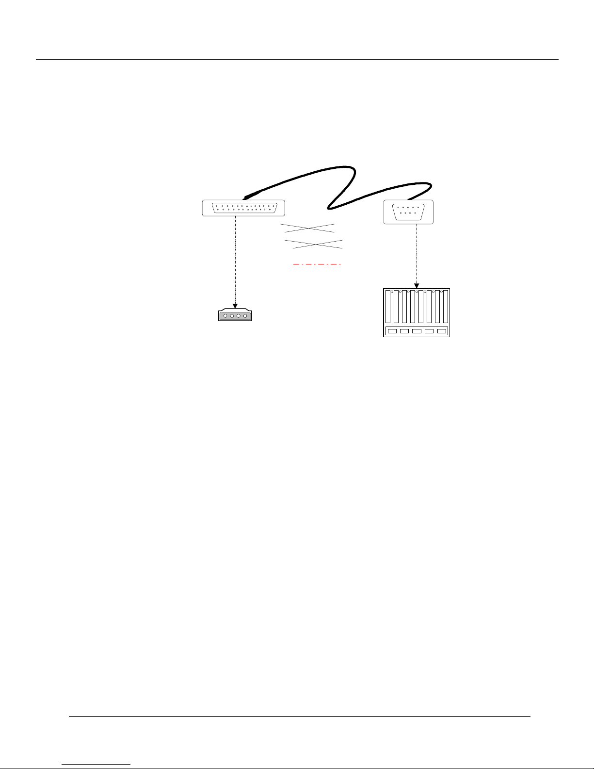
Configuring the Cajun P550 Switch (Layer 2 & Layer 3)
Figure 2-5.
DB25 M - RJ45
P/N 38210003
Typical Connection Between the Switch and a Modem
Typical Connection between Cajun
Switch and Modem
Pin 2 - TXD
Pin 3 - RXD
Pin 7 - GND
Pin 8 - DCD out
Modem
Pin 2 - TXD
Pin 3 - RXD
Pin 4 - DTR in
Pin5 - GND
pin 6 - NCpin 20 - DTR in
DB9M - RJ45
Cajun Switch
MDCE
Configuring the Serial Console Port as a PPP Console
You can reconfigure the console serial port as a PPP Console to support a dial-in PPP
connection using a modem.
Note: The lack of an IP address for the PPP serial interface causes the switch to
immediately return to sending the modem configuration string. Typing TTY
will re-access the CLI login prompt.
To configure the console serial port as a PPP console:
1. In the System Configuration section of the Web Agent window, select Console
Configuration. The Console Configuration dialog box opens.
2. Click PPP for your console type and click Select. The Console Port Configuration
dialog box opens.
3. Use Table 2-17 to change your console port settings.
Note: The only parameters you can change as a PPP console is baud rate and
flow control. The flow control settings are limited to None or Xon/Xoff.
2-26 Cajun P550 Switch Installation Guide
Page 49
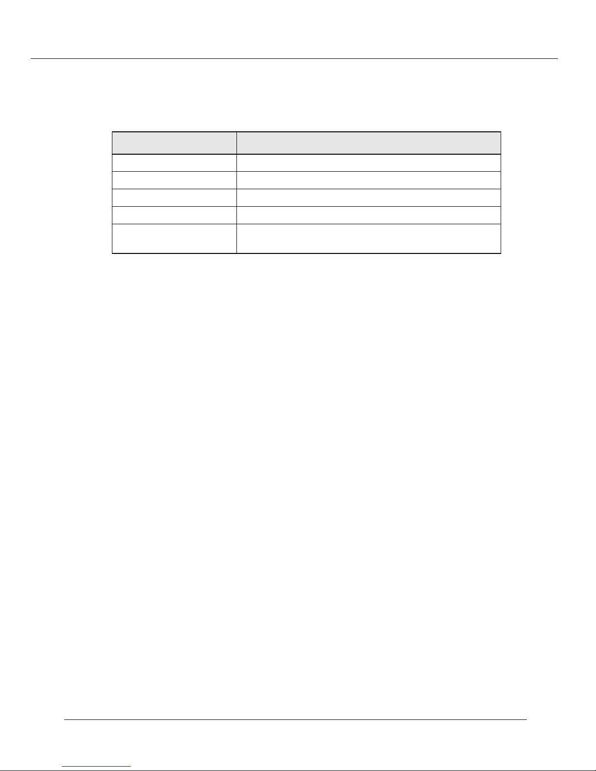
Configuring the Cajun P550 Switch (Layer 2 & Layer 3)
4. In the Modem Init Cmd field, enter your modem initialization command.
The default modem configuration string is AT&D0S0=1.
Table 2-18. Modem Configuration String Parameters
Parameter Definition
&D0 Disable DTR
S0=1 Auto-answer mode (one ring)
CD follows carrier Depends on modem
E0 Disable local echo
Software Flow Control
(Receive and Transmit)
Depends on modem
5. Click APPLY to save your changes, or CANCEL to restore previous settings.
Note: If you misconfigure your PPP serial console port, you can regain CLI access to
correct the configuration parameters. For more information, refer to
“Regaining Configuration Access to the PPP Serial Port Console”.
Safety Tip: To successfully dial-in with PPP to the switch, you must also configure an IP
address and interface for the PPP Serial Interface (Serial-Console).
Regaining Configuration Access to the PPP Serial Port Console
If the PPP serial port console is configured incorrectly, the command line interface (CLI)
becomes temporarily unavailable for reconfiguration.
To regain access to the CLI when the console port is in PPP mode:
1. In the console window, type TTY. The CLI login prompt displays. It may be
necessary to press Enter several times to see the login prompt. You may see the
modem init command string.
2. At the Login prompt, enter your user name. The password prompt displays.
3. At the Password prompt, enter your password. The Cajun CLI prompt displays.
4. Enter the PPP configuration commands necessary to start PPP. Refer to
“Configuring the Serial Console Port as a PPP Console”, earlier in this chapter, and
“Creating an IP Interface”, in Chapter 7, for more information on PPP
configuration commands.
5. After you complete your configuration settings, type exit at the CLI prompt to
reinvoke the modem control software and exit CLI mode.
Cajun P550 Switch Installation Guide 2-27
Page 50

Configuring the Cajun P550 Switch (Layer 2 & Layer 3)
Note:
You do not need to exit from CLI if the serial port console has been
configured as a TTY console, or if you do not intend to re-attempt
connecting using PPP.
Configuring Dial-Up Networking
To configure your PC for dial-up networking with a PPP serial port console:
From
1.
My Computer
Networking dialog box opens.
Note:
You must have dial-up networking installed on your PC.
2. Double-click Make New Connection to configure your modem. The Make New
Connection wizard opens.
3. In the Type a name for the computer you are dialing field, enter a
connection name for the computer you are dialing.
4. From the Select a Modem pull-down menu, select your modem and click
Configure. The Modem Properties dialog box opens.
, double-click
Dial-Up Networking
. The Dial-Up
5. Click the Connection tab. The Connection tab opens.
6. In Connection preferences, select the following:
• From the Data bits pull-down menu, select 8.
• From the Parity pull-down menu, select None.
• From the Stop bits pull-down menu, select 1.
7. Click Advanced. The Advanced Connection Settings dialog box opens.
8. In Use flow control, click Software (XON/XOFF).
9. Click OK to close the dialog box. The Modem Properties dialog box re-opens.
10. Click the Options tab. The Option tab opens.
11. In Connection control, click Bring up terminal window after dialing and
click OK. The Modem Properties dialog box closes and the wizard continues.
12. In the wizard dialog box, click Next and enter the telephone number you are
calling.
13. Click Next. The wizard reports that you have successfully configured a modem.
14. Click Finish. The wizard closes and the newly configured connection displays in
your Dial-Up networking program group.
2-28 Cajun P550 Switch Installation Guide
Page 51

Configuring the Cajun P550 Switch (Layer 2 & Layer 3)
15. Right-mouse click on your new connection and select Properties. The Properties
dialog box opens.
16. Click the Server Types tab and de-select all advanced options except TCP/IP.
17. Click TCP/IP Settings. The TCP/IP settings dialog box opens.
18. Click Specify an IP Address and enter the IP address of the serial port interface.
19. Click Server assigned name server addresses.
20. De-select Use IP header compression and Use default gateway on remote
network.
21. Click OK to close the TCP/IP dialog box.
22. Click OK to close the new connections properties dialog box.
Using Dial-Up Networking with a PPP Serial Port Console
To use TCP/IP applications (Telnet, HTTP, and SNMP) over your PPP serial port interface:
1. From My Computer, double-click Dial-Up Networking. The Dial-Up
Networking program group opens.
2. Double-click on the PPP modem previously created. The Connect To dialog box
opens.
3. Enter your password and click Connect. A Pre-Dial Terminal Screen opens.
When the modem has successfully connected, a Post-Dial Terminal Screen opens.
4. In the Post-Dial Terminal screen, login using your CLI user name and
password. It may be necessary to enter several carriage returns to view the Login
prompt.
5. At the CLI prompt, go to configuration mode and enter set console transfer PPP.
ASCII characters display below the CLI prompt. This is typical while the switch
attempts to connect via PPP.
6. In the Post-Dial Terminal screen, click Continue (F7). PPP verification
completes and the Connected To dialog box displays a message that the modem
connection has been successfully established.
Configuring the IP Interface for the PPP Console
To configure the PPP console with an IP address and mask:
1. Configure your console serial port as a PPP Console. See “Connecting a Modem”,
earlier in this chapter.
2. Connect your modem cable to the Cajun’s serial port.
Cajun P550 Switch Installation Guide 2-29
Page 52

Configuring the Cajun P550 Switch (Layer 2 & Layer 3)
3. From the IP Configuration section of the Web Agent, click Interfaces. The IP
Interfaces dialog box opens.
4. Click CREATE. The Add IP Interface dialog box opens.
5. From the VLAN pull-down menu, select Serial-Console. This specifies the
interface for the PPP console.
6. In the Network Address field, enter the IP address to be associated with the PPP
console port.
Note: If you do not enter a name for this interface, the IP address is used as the
interface name.
7. In the Mask field, enter the network mask IP address (for example,
255.255.255.0).
8. Click APPLY to save your changes, or CANCEL to restore previous settings.
Configuring a Static Route for the PPP Console
To configure a PPP Console static route:
1. Configure your console serial port as a PPP Console. Refer to “Connecting a
Modem”, earlier in this chapter.
2. From the IP Configuration section of the Web Agent window, click Static
Routes. The IP Static Routes dialog box opens.
3. Click CREATE. The Add IP Static Routes dialog box opens. This allows you to
define a static route for the PPP console.
4. In the Network Address field, enter the IP address to be associated with the PPP
console port.
5. In the Mask field, enter the network mask IP address (for example,
255.255.255.0).
6. In the Next-Hop Address field, enter the IP address of the gateway associated
with this static route.
7. Click APPLY to save your changes, or CANCEL to restore previous settings.
Hardware Requirements for Routing
To configure your switch as an IP/IPX router, you must first configure your Cajun switch
with the following hardware:
❒ Layer 3 supervisor module (mandatory)
2-30 Cajun P550 Switch Installation Guide
Page 53

Configuring the Cajun P550 Switch (Layer 2 & Layer 3)
❒ Layer 3 media modules (optional) including:
• 2-Port Gigabit Ethernet module
• 10-Port 100-Base-F module
• 12-Port 10/100-Base-T module
Configuring IP Routing on the Switch
The Cajun P550 Switch with Integrated Routing combines scalable wire speed IP Layer 3
switching (routing) with 10/100/1000 Ethernet Layer 2 switching (bridging) in a
high-capacity chassis-based system. The product emphasizes traditional,
standards-compliant IP operation and ample capacity to avoid bottlenecks.
For more detailed information on Cajun P550 Switch routing operations, refer to
“Routing with Layer 2 and Layer 3 Modules”, in
the
Cajun P550/P220 Switch Operation Guide
.
Minimum IP Routing Configuration Requirements
The configuration process for the Cajun P550 Switch with integrated routing has the
following minimum requirements for using IP routing:
❒ IP routing must be globally enabled.
❒ At least one routing protocol must be enabled (RIP, OSPF) if communication
between routers is necessary.
❒ Determine which interfaces need to have IP routing enabled.
❒ If you plan to expand your current network, create VLANs (subnets) to address
your network configuration.
❒ Assign an IP address, subnet mask, routing protocol, and multicast routing protocol
to each IP interface you configure.
Routing Configuration Quickstart
This section provides an overview of the LAN router configuration operation. For more
information on these configuration steps, see the sections referenced after each step.
To configure the switch as a LAN router:
1. Create a IP interface for each subnet. Refer to “Creating and Implementing
VLANs”, in
2. Create or assign a VLAN to the IP interface. Refer to “Assigning IP Interfaces to the
VLAN”, in
Cajun P550 Switch Installation Guide 2-31
the
Cajun P550/P220 Switch Operation Guide
the
Cajun P550/P220 Switch Operation Guide
.
.
Page 54

Configuring the Cajun P550 Switch (Layer 2 & Layer 3)
3. Bind ports to the VLANs assigned to the IP interfaces. Refer to “Viewing Switch
Port Parameters”, earlier in this chapter.
4. Assign an IP address and subnet mask to the VLAN. Refer to “Assigning IP
Interfaces to the VLAN”, in
5. Specify how the router will communicate with other routers. Refer to “Assigning IP
Interfaces to the VLAN”, in
OSPF and RIP parameters.
the
Cajun P550/P220 Switch Operation Guide
the
Cajun P550/P220 Switch Operation Guide
Configuring System Information
The System Information section of the Web Agent allows you to configure general
system information and settings, such as:
❒ Entering General System Information
❒ Enabling SNTP
.
, to configure
❒ Setting Summer Time Hours
❒ Displaying the Power System Statistics
❒ Displaying Cooling System Statistics
❒ Performing a System Reset
❒ Configuring Redundant Hardware
Entering General System Information
The system allows you to enter general system identification information from the Web
Agent. Use these fields to uniquely identify each switch:
❒ Switch name
❒ Device location
❒ Device contact
To change these values:
1. In the System Information section of the Web Agent window, click General. The
System Information dialog box opens (Figure 2-6).
2-32 Cajun P550 Switch Installation Guide
Page 55
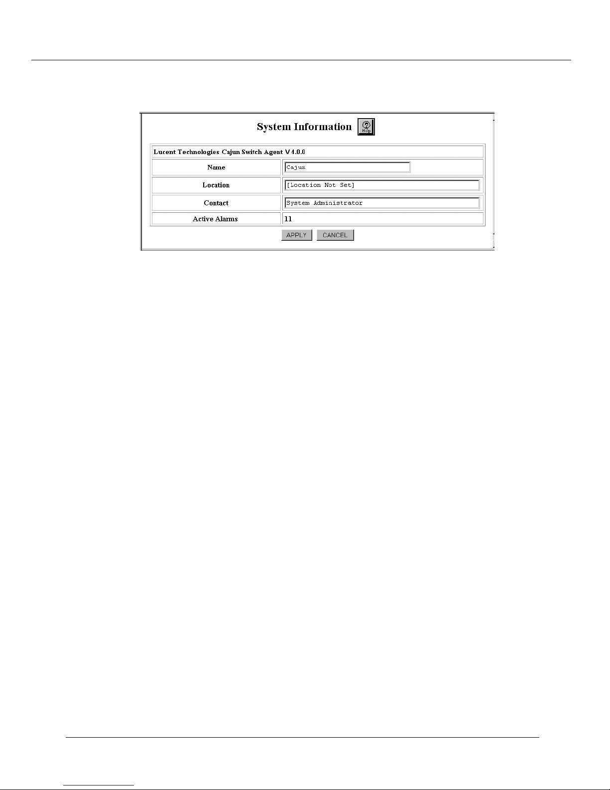
Configuring the Cajun P550 Switch (Layer 2 & Layer 3)
Figure 2-6. General System Information Dialog Box
2. In the Name field, enter a name for the switch.
3. In the Location field, enter the location for the switch (for example, floor and
closet location).
4. In the Contact field, enter information about the person who should be contacted
in the event of a problem.
5. Click APPLY to save your changes, or CANCEL to restore previous settings.
Enabling SNTP
The Simple Network Time Protocol (SNTP) ensures that you can automatically
synchronize time on all computers, switches, and other devices connected to your Cajun
P550 Switch. By enabling SNTP, you ensure that all devices connected to your switch
reflect the same time.
When you enable SNTP, you are required to set your time zone and the rule or dates of
Summer Time Hours followed by your location. For information about setting your time
zone, refer to “Setting One-Time Summer Time Hours”. For information about setting
Summer Time Hours, refer to “Setting Summer Time Hours”.
To enable SNTP:
1. In the System Information section of the Web Agent window, click System
Clock. The System Clock dialog box opens.
2. In the Clock Options section, click Simple Network Time Protocol (SNTP).
The SNTP Client Configuration dialog box opens.
3. From the Enable State pull-down menu, select Enable.
Cajun P550 Switch Installation Guide 2-33
Page 56

Configuring the Cajun P550 Switch (Layer 2 & Layer 3)
4. In the Server IP Address field, type the IP address of the switch for which you
enable SNTP.
5. Click Apply. SNTP is enabled for the switch.
Setting Summer Time Hours
Summer Time Hours, also referred to as Daylight Savings Time (DST), is the strategy of
moving clocks ahead to provide greater amounts of daylight in the afternoon and to
standardize time with other parts of the world. In many parts of the world, the Summer
Time Hours algorithm is based on a standardized rule. For example, in the Western
hemisphere, the rule used by most locations in Canada, Mexico, and the United States is
to set clocks forward by one hour at 2:00 a.m. on the first Sunday in April and back an
hour at 2:00 a.m. on the first Sunday in October annually. Many countries in Europe
and Asia follow similar rules. The offset, or amount of time by which the clock is set
forward or backward, varies from country to country.
Many parts of the world follow a one-time change of Summer Time Hours. When you
configure the switch for these locations, you reset the clock by specifying a scheduled
time and date.
Note: If you upgrade the Cajun P550 from a previous version, your local time
settings are saved as Greenwich Mean Time values. Ensure that you change
the Summer Time Hours Algorithm before you set the clock.
Setting Recurring Summer Time Hours
To set recurring Summer Time Hours:
1. In the System Information section of the Web Agent window, click System
Clock. The System Clock dialog box opens.
2. In Clock Options, click Summer Time Hours Algorithm. The Summer Time
Hours Configuration box opens.
3. From the Enable State pull-down menu, select Enable.
4. In the Offset cell of the Value column, enter the reset value for the clock in
minutes.
For example, if you intend to reset the clock forward or backward by one hour,
retain the default value of 60 minutes.
5. Click Recurring.
Note: The Web Agent enables you to select the boxes next to both Recurring and
One-time Summer Time Hours. However, the option to set both Recurring
and One-time hours is not provided.
2-34 Cajun P550 Switch Installation Guide
Page 57

Configuring the Cajun P550 Switch (Layer 2 & Layer 3)
6. Use Table 2-19 for information about configuring Summer Time Hours.
Table 2-19. Recurring Summer Time Hours Configuration
Parameter Definition
Recurring Select if Summer Time Hours is defined by a rule such as
Daylight Savings Time (DST). All Start and End fields
associated with Recurring Summer Time Hours provide the
default values for Daylight Savings Time.
When you select recurring Summer Time Hours, you
indicate the time, in hours and minutes, on a specified day,
week, and month that Summer Time Hours begin and end.
Start Specifies the start of Summer Time Hours.
End Specifies the end of Summer Time Hours.
Week Select the week during which you want recurring Summer
Time Hours to start or end. The selected week should
reflect the day on which Summer Time Hours start. For
example, if Summer Time Hours start on the first Sunday
in April, select the First week. Options include:
• First - First week of the month, the default Start value,
when Daylight Savings Time starts in the Western
hemisphere.
• Second - Second week of the month.
• Third - Third week of the month.
• Fourth - Fourth week of the month.
• Last - Remaining days of the month that form the last
week of the month. Last is specified as the default End
value, denoting when Daylight Savings Time ends in
the Western hemisphere.
Day Select the day of the week when you want recurring
Summer Time Hours to start or end. Options are based on a
seven-day week and include:
• Sunday - the default Start and End values. In the
Western hemisphere, DST starts on the first Sunday in
April and ends on the last Sunday in October.
• Monday
•Tuesday
•Wednesday
• Thursday
•Friday
•Saturday
Cajun P550 Switch Installation Guide 2-35
Page 58
Configuring the Cajun P550 Switch (Layer 2 & Layer 3)
Table 2-19. Recurring Summer Time Hours Configuration
Parameter Definition
Month
Hour
Minutes
7.
Select the month when recurring Summer Time Hours start
or end. The twelve months of the Gregorian calendar are
provided.
For recurring Summer Time Hours, the default Start value
is April, the month during which DST starts in the Western
hemisphere. The default End value is October, the month
during which DST ends in the Western hemisphere.
Enter a value to represent the hour when Summer Time
Hours start or end for Recurring settings.
For Recurring Summer Time Hours, the default value is 02,
meaning 2:00 a.m., for both Start and End hours.
Enter a value to represent the number of minutes into the
hour when Summer Time Hours start or end for Recurring
Summer Time Hours. The default value is 00 for both Start
and End minutes.
To set Summer Time Hours that recur annually, according to a rule:
Select
a.
Select values for the Week, Day, and Month when Summer Time Hours start
b.
Recurring
.
and end.
Enter values for the Hour and Minutes when Summer Time Hours start and
c.
end.
8.
Click
APPLY
to save your changes, or
Setting One-Time Summer Time Hours
To set Summer Time Hours that are not based on a standard rule:
1. In the System Information section of the Web Agent window, click System
Clock. The System Clock dialog box opens.
2. In Clock Options, click Summer Time Hours Algorithm. The Summer Time
Hours Configuration box opens.
3. From the Enable State pull-down menu, select Enable.
4. In the Offset cell of the Value column, enter the reset value for the clock in
minutes.
For example, if you intend to reset the clock forward or backward by one hour,
retain the default value of 60 minutes.
5. Click One-Time.
CANCEL
to restore previous settings.
2-36 Cajun P550 Switch Installation Guide
Page 59

Configuring the Cajun P550 Switch (Layer 2 & Layer 3)
Note:
The Web Agent enables you to select the boxes next to both Recurring and
One-time Summer Time Hours. However, the option to set both Recurring
and One-time hours is not provided.
Use Table 2-20 to configure Summer Time Hours on a one-time basis.
6.
Table 2-20. One-Time Summer Time Hours Configuration
Parameter Definition
One-time
Start
End
Week
Select if Summer Time Hours change one time, such as on
a specified date.
When you select one-time Summer Time Hours, you
indicate the time and date on which Summer Time Hours
begin and end.
Specifies the start of Summer Time Hours.
Specifies the end of Summer Time Hours.
Select the week of the month during which you want
recurring Summer Time Hours to start or end. Options
include:
•
•
•
•
•
- First week of the month, the default Start value,
First
when Daylight Savings Time starts in the Western
hemisphere.
Second
- Third week of the month.
Third
Fourth
- The final days of a month, such as the 29th,
Last
30th, and 31st days of a month. Last is specified as the
default End value, denoting when Daylight Savings
Time ends in the Western hemisphere.
- Second week of the month.
- Fourth week of the month.
Day
Cajun P550 Switch Installation Guide 2-37
Select the day of the week when you want recurring
Summer Time Hours to start or end. Options are based on a
seven-day week and include:
•
Sunday
Western hemisphere, DST starts on the first Sunday in
April and ends on the last Sunday in October.
• Monday
•Tuesday
•Wednesday
• Thursday
•Friday
•Saturday
- The default Start and End values. In the
Page 60
Configuring the Cajun P550 Switch (Layer 2 & Layer 3)
Table 2-20. One-Time Summer Time Hours Configuration (Continued)
Parameter Definition
Month
Hour
Minutes
7.
Select the month when one-time Summer Time Hours start
or end. The twelve months of the Gregorian calendar are
provided.
For a one-time setting of Summer Time Hours, the default
value for start and end months is January.
Enter a value to represent the hour when Summer Time
Hours start or end for One-time settings. The default value
is 00.
Enter a value to represent the number of minutes into the
hour when Summer Time Hours start or end for One-time
Summer Time Hours. The default value is 00 for both Start
and End minutes.
To set Summer Time Hours on a one-time basis:
a.
b.
Select
Set the
One-Time
date
.
on which Summer Time Hours start and end by selecting the
Month, Day, and Year on which Summer Time Hours start and end.
c.
Enter
values
for the Hour and Minutes when Summer Time Hours start and
end.
Click
8.
APPLY to save your changes, or CANCEL to restore previous settings.
Setting the System Clock
The system clock is used for setting traps, alarms, and other events of the switch. Set
SNTP and Summer Time Hours before you set the system clock.
To set the system clock:
1. In the System Information section of the Web Agent window, click System
Clock. The System Clock dialog box opens.
2. In the Current Time Setting fields, enter the time using 24-hour time format (for
example, 10 p.m. is 22 00 00).
3. From the Time Zone pull-down menu, select your time zone.
4. In the Current Date Setting fields, enter the current month, date, and year.
5. Click APPLY to save your changes, or CANCEL to restore previous settings.
Note: The system clock does not automatically change with Daylight Savings Time.
2-38 Cajun P550 Switch Installation Guide
Page 61
Setting the Temperature System
You can set the upper and lower temperature warning systems for your switch’s
backplane and slot 1.
To configure the temperature warning systems:
Configuring the Cajun P550 Switch (Layer 2 & Layer 3)
In the
1.
Temperature
Enter the desired temperature
2.
sensors
CPU sensor
Click on
3.
System Information
. The Temperature System dialog box opens.
. For Layer 3 switches, also enter the desired temperature
.
APPLY
to save your changes, or
section of the Web Agent window, click
warnings
for the
defaults.
Note:
The supervisor modules shut down the switching modules if the temperature
reaches the Shutdown temperature. The modules are restarted if the
temperature goes below the Upper Warning Temperature. The default
Shutdown temperatures are conservative for the slot 1 sensor (50° C) and
backplane sensor (50° C). They can be safely set to 60° C, but settings higher
than 60° C are not recommended. You can set the shutdown temperature to a
value lower than 50° C to ensure prompt notification if a fan fails.
Displaying the Power System Statistics
To display the power system statistics:
switch backplane
Defaults
and
slot 1
warning
for the
to restore the temperature
In the
1.
System
Use Table 2-21 to review your power system statistics:
2.
System Information
. The Power System dialog box opens.
Table 2-21. Power System Statistical Parameters
section of the Web Agent window, click
Power
Parameter Definition
Power Supply Identifies the power supply.
Status Identifies whether the power supply is detected.
Type Describes the type of power supply detected.
Total System Power Displays the total system power in Watts.
Current Power Available Displays the current power available.
Cajun P550 Switch Installation Guide 2-39
Page 62

Configuring the Cajun P550 Switch (Layer 2 & Layer 3)
Note:
The power system settings will only display 600W of available power with
three power supplies installed. This is because the switch uses a maximum of
two power supplies. The third power supply is held in reserve for redundancy
in the event one of the other power supplies fails.
Displaying Cooling System Statistics
To display the switch’s cooling system status:
In the
1.
System
Ensure that all the individual components are operational by checking the status
2.
column for each component.
If a component’s status is non-operational, power down the switch and contact a
3.
service representative to diagnose the failing unit.
System Information
. The Cooling System dialog box opens.
section of the Web Agent window, click
Configuring Redundant Hardware
In both Layer 2 and Layer 3 models, the Cajun P550 switch provides a redundant
backplane to ensure that if a controller or an element fails, the switch will continue to
route data properly. The redundant components are available as separate options.
Cooling
When the redundant controller and element are installed, the backplane consists of the
following parts:
❒
One main controller
❒
One redundant controller
❒
Six switch elements
❒
One redundant element
2-40 Cajun P550 Switch Installation Guide
Page 63

Configuring the Cajun P550 Switch (Layer 2 & Layer 3)
Figure 2-7. Layout of Redundant Backplane
Redundant
Element
Elements
6 - 4
Primary
Controller
Redundant
Controller
Elements
3 - 1
The Cajun P550 switch is equipped with diagnostics to monitor the status of switch
controllers and elements. When an element fails, diagnostics run automatically and test
the hardware. In the Web Agent, information about a failed controller or element
displays in the Switch Fabric Status dialog box.
If the primary controller fails, the redundant controller takes over switch operation until
you replace the primary controller. If an element fails, the redundant element takes over
the function of the failed element until you replace the element.
The following sections explain how to:
❒ Install Redundant Hardware
❒ Replace the Primary Controller
❒ Replace an Element
Installing Redundant Hardware
By default, the switch is configured without the redundant controller or element, as
shown in Figure 2-8.
Cajun P550 Switch Installation Guide 2-41
Page 64

Configuring the Cajun P550 Switch (Layer 2 & Layer 3)
Figure 2-8. Default Hardware Configuration
Elements
3 - 1
Elements
6 - 4
Primary
Controller
To install the redundant modules and enable module redundancy:
Shut down the switch.
1.
WARNING:
Install the redundant controller in the slot to the left of the primary controller. (Slot
2.
Before replacing switch controllers or elements, turn off the switch.
1 in Figure 3-8).
Note:
Controllers and elements are equipped with keys to ensure that a controller
cannot be inserted into an element slot and an element cannot be inserted
into a controller slot.
Install the redundant element in the slot to the left of the sixth element. (Slot 0 in
3.
Figure 3-8).
Restart the switch and login.
4.
5.
In the
System Information
section of the Web Agent window, click Switch
Fabric. The Switch Fabric Status dialog box opens.
If the redundant controller and element installed properly, settings display as in
Figure 2-9.
2-42 Cajun P550 Switch Installation Guide
Page 65
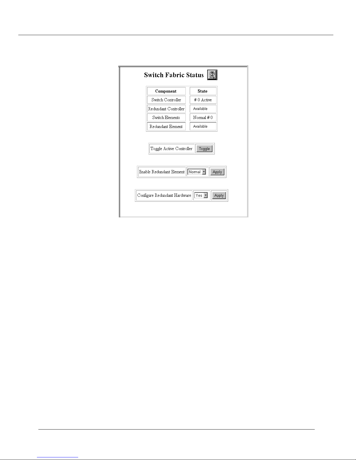
Configuring the Cajun P550 Switch (Layer 2 & Layer 3)
Figure 2-9. Properly-Installed Redundant Hardware Settings
6. From the Configure Redundant Hardware pull-down menu, select Yes.
7. Click APPLY to save your changes.
The redundant hardware is enabled. If the primary controller fails, the redundant
controller takes over in its place. If an element fails, the redundant element takes
over in its place.
Replacing the Primary Controller
If the primary controller fails, you are notified by a console message and an event log
message. In the Web Agent, the Switch Controller field displays # 0 Failed. If the
switch is installed with a redundant controller, the redundant controller automatically
takes over the operation of the failed primary controller.
To replace the primary controller:
1. In the System Information section of the Web Agent window, click Switch
Fabric. The Switch Fabric Status dialog box displays.
2. From the Configure Redundant Hardware pull-down menu, select No.
3. Click APPLY to disable the primary controller.
Cajun P550 Switch Installation Guide 2-43
Page 66

Configuring the Cajun P550 Switch (Layer 2 & Layer 3)
4. Shut down the switch.
WARNING:Before replacing switch controllers or elements, you must turn off the
switch.
5. Replace the failed primary controller by inserting it in the slot to the right of the
redundant controller and to the left of element three. (See Figure 2-7)
6. Restart the switch and login.
7. In the System Information section of the Web Agent, click Switch Fabric. The
Switch Fabric Status dialog box displays.
8. From the Configure Redundant Hardware pull-down menu, select Yes.
9. Click APPLY to enable the redundant controller.
The Switch Controller field displays # 1 Active to show that the redundant
controller is now enabled.
10. In the Toggle Active Controller field, click Tog gle to restore control to the
primary controller.
The Switch Controller field displays # 0 Active to show that the primary controller
is now enabled.
Replacing an Element
If an element fails, you are notified by a console message and an event log message. In
the Web Agent, the Switch Elements field displays # Failed <number>, where <num be r >
is the number that indicates the failed element.
To configure the redundant element:
1. In the System Information section of the Web Agent window, click Switch
Fabric. The Switch Fabric Status dialog box displays.
2. From the Configure Redundant Hardware pull-down menu, select No.
3. Click Apply to disable the failed element.
4. Shut down the switch.
WARNING:Before replacing switch controllers or elements, you must turn off the
switch.
5. Replace the failed element by inserting it into the appropriate slot. (See Figure
2-7.)
6. Restart the switch and login.
2-44 Cajun P550 Switch Installation Guide
Page 67

7. In the System Information section of the Web Agent window, click Switch
Fabric. The Switch Fabric Status dialog box displays.
8. From the Configure Redundant Hardware pull-down menu, select Yes and
click APPLY to enable the redundant element.
The Switch Elements field displays Normal # 0 to show that the redundant element
is now enabled.
9. From the Enable Redundant Element pull-down menu, select Normal and
click APPLY.
The Switch Element field displays Normal # 0 to show that the replaced element is
now enabled.
Performing a System Reset
To perform a system reset:
1. In the System Information section of the Web Agent window, click System
Reset. The System Reset Page dialog box opens.
Configuring the Cajun P550 Switch (Layer 2 & Layer 3)
2. Click Save to save your running configuration to the startup configuration before
performing a system reset.
3. Click Yes to reset the switch, or No to cancel the operation.
Managing Configuration Files
You can manage the system files that contain the configuration data for your Cajun P550
switch. When you first install the switch, or upgrade from a previous installation, your
configuration parameters are stored in a startup.txt file located in the switch’s
Non-Volatile Random Access Memory (NVRAM). When the switch is restarted, the
startup.txt file runs and stores configuration parameters in volatile RAM as a running
configuration.
Changes you make to the switch configuration are automatically recorded in RAM, but
not in NVRAM. When you want to retain your current configuration, you must
manually save it to NVRAM through the Web Agent or the Command Line Interface
(CLI). For information about how to save your running configuration file to your startup
configuration, refer to “Copying Running Configuration to Startup Configuration” later
in this section. To determine changes you have made to your running configuration, you
can view and compare your running and startup configuration files.
Cajun P550 Switch Installation Guide 2-45
Page 68

Configuring the Cajun P550 Switch (Layer 2 & Layer 3)
Viewing Your Running Configuration
To view your running configuration:
❒ In the CLI Configuration section of the Web Agent window, click Running
Configuration.
Or
❒ In priv.mode in the Command Line Interface, enter show running_config.
Viewing Your Startup Configuration
To view your startup configuration:
❒ In the CLI Configuration section of the Web Agent window, click Startup
Configuration.
Or
❒ In priv.mode in the Command Line Interface, enter show startup_config.
Viewing Your Script Execution Log File
Each time the startup.txt file or other script runs, a log file is generated. Log files contain
the data that scripts return.
To view your script execution log file:
❒ In the CLI Configuration section of the Web Agent window, click Script Log
File.
The Script Execution Log File dialog box opens showing the contents of the script
execution log file.
Or
❒ In priv.mode in the Command Line Interface, enter show file logfile.txt.
Copying Configuration Files
If you modify your running configuration through the Command Line Interface (CLI) or
the Web Agent, and you want your changes to replace your startup configuration, copy
your running configuration to your startup configuration. Before you copy a running
configuration over your startup configuration, copy your startup configuration to a file
on the switch or on a TFTP server using the Web Agent or the Command Line Interface.
On the switch, configuration files are automatically saved as text files using the *.txt
2-46 Cajun P550 Switch Installation Guide
Page 69

Configuring the Cajun P550 Switch (Layer 2 & Layer 3)
extension. On a TFTP server, you can edit the startup.txt file using a text editor of your
choice and save copies of it with or without a file extension.
Copying Running Configuration to Startup Configuration
To save your running configuration as your startup configuration in NVRAM:
1. In the CLI Configuration section of the Web Agent window, click Config File
Management.
2. Click Save to save your running configuration as your startup configuration.
Or
In priv.mode in the CLI, enter:
copy ru nn ing -c onfig star tup -c on fig
Copying Files
Using the Configuration File Management dialog box, you can copy files to and from
multiple locations. For example, if you modify your running configuration and you want
to reinstate your startup configuration parameters, you can copy your startup
configuration to your running configuration in volatile RAM. Also, you can upload
configuration and other ASCII files from the switch to a TFTP server. Likewise, you can
download files by copying files from a TFTP server directory to the switch or to a startup
or running configuration file.
To copy files:
1. In the CLI Configuration section of the Web Agent, click Config File
Management. The Configuration File Management dialog box opens.
Cajun P550 Switch Installation Guide 2-47
Page 70

Configuring the Cajun P550 Switch (Layer 2 & Layer 3)
2. Use Table 2-22 for information about copying a source file to a TFTP server
destination:
Table 2-22. Configuration File Management Parameters
Parameter Description Options
Save Running-Config
to Startup-Config
Copy Source Specifies the source file to
Source Filename Specifies the path and
Copy Destination Specifies the destination
Saves the running
configuration to the
startup configuration
be copied
name of the source file
of the file to be copied
N/A
•Unspecified- Specifies the intialized
value. The initialized value is blank.
• File - Specifies a source file located on the
switch in NVRAM.
• Running-Config - Specifies a running
configuration.
• Startup-Config - Specifies a startup
configuration.
• TFTP Server - Specifies a source file
located in a directory on a TFTP server.
Source files can be ASCII files in NVRAM
available for upload or files located on a TFTP
server available for download
•Unspecified - Specifies the intialized
value. The initialized value is blank.
• File - Specifies that a source is copied or
downloaded to NVRAM.
• Running-Config - Specifies that a source
is copied to the running configuration.
• Startup-Config - Specifies that a source is
copied to the startup configuration.
• TFTP Server - Specifies that a source is
copied to a TFTP server location.
Destination Filename Specifies the location of
TFTP Server IP Address Specifies the IP address of
3. From the Copy Source pull-down menu, select one of the following:
2-48 Cajun P550 Switch Installation Guide
the destination
a source or destination
TFTP server
Configuration files and other files can be
copied to NVRAM on the switch or to a TFTP
server as a destination location.
Copy (download) source files, located on a
TFTP server, to your running configuration,
your startup configuration, or a location on
the switch. Or, copy (upload) your
configuration files, or a file located on the
switch, to a TFTP server.
Page 71

Configuring the Cajun P550 Switch (Layer 2 & Layer 3)
• Running-Config
configuration, to a file located on the switch, or to a file located on a TFTP
server.
•Startup-Config
configuration, to a file located on the switch, or to a file located on a TFTP
server.
•
- To copy a file stored on the switch to your running or startup
File
configuration, to a location on the switch, or to a location on a TFTP server.
• TFTP Server
configuration or to a file on the switch.
If you select
file in the
From the
4.
File
Source Filename
Copy Destination
• Running-Config
located on the switch or on a TFTP server, to your running configuration.
•Startup-Config
located on the switch or on a TFTP server, to your startup configuration.
- To copy your running configuration to your startup
- To copy your startup configuration to your running
- To copy a file stored on a TFTP server to your running or startup
or
TFTP Server
, also provide the path and filename of the source
field.
pull-down menu, select one of the following:
- If you are copying your startup configuration, or other file
- If you are copying your running configuration, or other file
•File
- If you are copying your startup or running configuration, another file
located on the switch, or a file located on a TFTP server to a file on the switch.
• TFTP Server
- If you are copying your startup or running configuration, or
another file located on the switch, to a location on a TFTP server.
If you select
destination file in the
In
5.
TFTP Server IP Address
File
or
TFTP Server
Source Destination
, enter the IP address of the source or destination TFTP
, also provide the path and filename of the
field.
server, if applicable.
6.
Click
. Your source configuration or file is copied to your specified
Copy
destination.
Note:
The Web Agent returns an
Invali d op era ti on !
error message if you
attempt to copy:
• The current running configuration to the running configuration.
• The startup configuration to the same startup configuration.
• The specified TFTP server to a TFTP server.
Cajun P550 Switch Installation Guide 2-49
Page 72

Configuring the Cajun P550 Switch (Layer 2 & Layer 3)
Viewing the Status of a TFTP Transfer
After you have copied the startup configuration or other files to a TFTP server, you can
check the status of the TFTP transfer to ensure that files copied correctly.
To view the status of a TFTP transfer:
1. In the CLI Configuration section of the Web Agent, click Config File
Management. The Configuration File Management dialog box opens.
2. In the Get Status of Most Recent TFTP Copy field, click Status.
2-50 Cajun P550 Switch Installation Guide
Page 73

A
Product Specifications
Power
AC input voltage: 100-120/200-240 VAC @ +6%, -10%
Frequency: 50 - 60 Hz
Maximum Power Consumption:8.0 A @ 120 V
4.0 A @ 240 V
Operating/Physical
Operating Temperature: 0° to 40° C
Safety
EMI
Storage Temperature: -20° to 80° C
Relative Humidity: 5% to 95% noncondensing
Physical Dimensions: 17.5" W x 18" D x 10.5" H
UL 1950
EN60950
CSA 22.2-No. 950
IEC 950
TUV GS
FCC 15J, Class A
CE Mark
Cajun P550 Switch Installation Guide A-1
Page 74

Product Specifications
EN55022 Class A
CISPR 22 Class A
A- 2
Cajun P550 Switch Installation Guide
Page 75

Index
Numerics
10/100 port
auto negotiation speed/duplex advertisement
10/100 port parameter
auto-negotiation mode
category
duplex mode
flow control mode
name
port PACE priority
rate limit burst size
rate limit mode
rate limit rate
speed mode
10BASE-T Crossover patch cables
10Base-T crossover patch cables
16MB
3COM
Virtual LAN trunking modes
3Com mapping table
non-VLAN switch port parameters
switch port configuration parameters
3Com SuperStack, parameters
automatic VLAN creation
port VLAN
trunk mode
VLAN bindings
, 2-11
, 2-11
, 2-11
, 2-12
, 2-12
, 2-11
, 1-3
, 2-21
, 2-21
, 2-21
, 2-11
, 2-11
, 2-12
, 2-12
, 1-1
, 2-5
, 2-16
, 2-20
, 2-21
A
AC power source
access
SNMP communities parameters
access level
configuring SNMP communities
active backpressure
adding a user
password
user logins
user name
admin
SNMP security level
Air Flow Requirements
all module ports configuration
all ports configuration, gigabit ports
allow learning
non-VLAN switch port parameters
, 1-2
, 2-23
, 2-24
, 2-11
, 2-6
, 2-6
, 2-6
, 2-6
, 2-24
, 1-2
, 2-12
, 2-8
, 2-19
, 2-16
, 2-11
switch port configuration parameters
assignment
Virtual LANs, configuring
Audience of Manual
auto negotiation speed/duplex advertisement
10/100 port
automatic VLAN creation
3Com SuperStack parameters
Bay Networks System 5000 parameters
Cisco Catalyst 5000 parameters
switch port configuration parameters
auto-negotiation
Fast Ethernet module
auto-negotiation mode
10/100 port parameter
, ix
, 2-11
, 2-16
, 2-17
, 2-21
, 2-10
, 2-11
, 2-15
, 2-21
, 2-20
, 2-15
B
baud rate
console serial port settings
Bay Networks System 5000, parameters
automatic VLAN creation
port VLAN
trunk mode
VLAN bindings
bind to all
Virtual LAN binding options
bind to received
Virtual LAN binding options
binding options
Virtual LANs
, 2-21
, 2-21
, 2-21
, 2-17
, 2-25
, 2-21
, 2-17
, 2-17
C
cable distances, recommended
cables
installation
category
10/100 port parameter
gigabit port parameters
category 5 cables
Cisco Catalyst 5000 parameters
port VLAN
Cisco Catalyst 5000, parameters
automatic VLAN creation
trunk mode
VLAN binding
VTP snooping
, 1-7
, 1-7
, 2-20
, 2-20
, 2-20
, 2-20
, 1-8
, 2-11
, 2-8
, 2-20
Index 1
Page 76

CLI
regaining access
communities
configuring SNMP
SNMP
, 2-23
community string
configuring SNMP
SNMP communities parameters
Components
configuration
invalid copies
configuration file management
copy destination
copy source
destination filename
save running configuration to startup
source filename
TFTP server IP address
configuration files
configuration revision number
VTP snooping parameters
configure ports
gigabit module
configuring a Fast Ethernet module
configuring a redundant element
configuring fast start mode
configuring flow control mode
gigabit module
configuring physical port parameters
gigabit ports
configuring port name
Fast Ethernet module
configuring port VLAN parameters
configuring service port
gigabit module
configuring the PPP console static route
configuring the serial port console
PPP console
configuring the temperature system
configuring user port
gigabit module
configuring VTP snooping
connecting a modem
connecting the power supplies
installation
console serial port
changing
console serial port configuration
PPP (Layer 3 only)
TTY (Layer 3 and Layer 2)
console serial port settings, changing
baud rate
data bits
, 1-1
configuration
, 2-24
, 2-25
, 2-27
, 2-23
, 2-23
, 2-49
, 2-48
, 2-48
, 2-48
, 2-48
, 2-48
, 2-48
, 2-45
, 2-19
, 2-7
, 2-44
, 2-21
, 2-8
, 2-8
, 2-9
, 2-16
, 2-8
, 2-26
, 2-8
, 2-18
, 2-25
, 1-10
, 2-24
, 2-24
, 2-25
, 2-23
, 2-9
, 2-39
, 2-30
flow control
parity
stop bits
Contacing Lucent
controller redundancy
enabling
conventions
cooling system status
displaying
Copper Cable Lengths
copy destination
configuration file management
copy source
configuration file management
copying
configurat ion
invalid combinations
from the switch or server to a configuration file
running configuration to startup configuration
startup configuration to running configuration
to a TFTP server
to the switch
copying files
copying from/to a TFTP server
copying source files
copying the running configuration
copying the startup configuration
Crossover Cables
current power available
power system statistical parameters
, 2-25
, 2-25
, 2-25
, x
, 2-42
, ix
, 2-40
, 1-9
, 2-48
, 2-48
, 2-49
, 2-47
, 2-47
, 2-49
, 2-49
, 2-47
, 2-49
, 2-49
, 1-7
, 2-39
D
data bits
console serial port settings
day
one-time summer time hours configuration
summer time hours configuration
default password
designating a switch fabric
destination filename
configuration file management
diagnostics
for switch hardware
dial-up networking
configuring with a PPP serial port console
displaying IPX RIP interface statistics
displaying the cooling system status
displaying the power system statistics
document conventions
, 2-3
, ix
, 2-25
, 2-35
, 2-41
, 2-48
, 2-41
, 2-1
, 2-40
, 2-39
, 2-47
, 2-47
, 2-47
, 2-37
, 2-28
2 Index
Page 77

documentation
feedback
online
documentation feedback
domain name
VTP snooping parameters
duplex mode
10/100 port parameter
Fast Ethernet module
, viii
, viii
, viii
, 2-19
, 2-11
, 2-10
E
editing general system information
Ejectors
electrostatic discharge
Electrostatic Discharge (ESD)
enabling controller redundancy
enabling fast start mode for all ports on a module
enabling fast start mode for individual ports
enabling gigabit ports
enabling SNTP
enabling the rate limit mode
end
, 1-6
preventing
Fast Ethernet module
one-time summer time hours configuration
summer time hours configuration
, 1-3
, 2-7, 2-9
, 2-33
, 2-10
, 2-32
, 1-3
, 2-42
, 2-22
, 2-35
F
Fast Ethernet module
auto-negotiation mode, enabling
configuring
rate limit mode, enabling
Fast Ethernet module, configuring
auto-negotiation duplex advertisement
auto-negotiation speed advertisement
duplex mode
flow control mode
pace priority mode
port name
rate limit burst size
rate limit rate
service port
speed mode
user port
fast start
switch port configuration parameters
fast start mode
configuring
fast start mode (all ports)
enabling
fast start mode (individual ports)
enabling
, 2-9
, 2-10
, 2-10
, 2-10
, 2-10
, 2-9
, 2-10
, 2-10
, 2-9
, 2-10
, 2-9
, 2-21
, 2-22
, 2-22
, 2-10
, 2-10
, 2-10
, 2-15
, 2-22
, 2-37
fault-tolerant switch fabric
designating
Female DTE-to-RJ-45 connector
Fiber Link Distances
files
copying
startup.txt
flow control
console serial port settings
flow control mode
10/100 port parameter
Fast Ethernet module
gigabit port parameters
frame tags
switch port configuration parameters
frame tags, configuring
Virtual LANs
, 2-41
, 1-1
, 1-8
, 2-49
, 2-45
, 2-25
, 2-11
, 2-10
, 2-9
, 2-17
G
general system information, setting
device contact
device location
switch name
gigabit module
configure ports
gigabit module, configuring
flow control mode
port name
port pace priority
ports
, 2-7, 2-9
service port
user port
gigabit port name
configuring
gigabit port parameters
category
flow control mode
port name
port PACE priority
remote fault detect
gigabit ports
configuring physical port parameters
enabling
Ground, electrical
, 2-32
, 2-32
, 2-32
, 2-7
, 2-8
, 2-7
, 2-8
, 2-8
, 2-8
, 2-7
, 2-8
, 2-9
, 2-8
, 2-9
, 2-9
, 2-7, 2-9
, 1-3
H
hardware requirements for routing
hour
one-time summer time hours configuration
summer time hours configuration
hunt group
non-VLAN switch port parameters
, 2-30
, 2-15
, 2-8
, 2-38
, 2-36
, 2-19
Index 3
Page 78

switch port configuration parameters
switch port parameter
, 2-13
I
IEEE-802.1Q
Virtual LAN trunking mode
installation
cable distances
cable types
connecting th power supplies
location
powering on the system
preventing electrostatic discharge
rack mount
relative humidity
installing
modules
table top
installing redundant controllers
IP address
configuring SNMP communities
SNMP communities parameters
IPX RIP interface statistics
displaying
, 1-8
, 1-7
, 1-2
, 1-4
, 1-2
, 1-6
, 1-5
, 2-1
, 2-16
, 1-10
, 1-10
, 1-3
, 2-42
, 2-23
, 2-23
K
known mode
non-VLAN switch port parameters
switch port configuration parameters
, 2-20
L
LAN router
configuration
Layer 2 switching (bridging)
Layer 3 switching (routing)
LEDs
, 1-11
link s
switch port parameter
location of hardware
logging in
Web Agent
, 2-31
, 2-31
, 2-31
, 2-13
, 1-2
, 2-6
M
MAC address
switch port parameter
Male DCE-to-RJ-45 connector
Male DTE-to-RJ-45 null modem connector
minutes
one-time summer time hours configuration
summer time hours configuration
, 2-13
, 1-1
, 2-36
, 2-15
, 2-16
, 1-1
, 2-38
mirror port
switch port configuration parameters
modem
connecting
modem configuration string parameters
&D0
CD follows carrier
E0
, 2-27
S0=1
software flow control
module
switch port parameters
Module Status LED
Modules
ejectors
modules
installing
modules & ports
month
one-time summer time hours configuration
summer time hours configuration
, 2-25
, 2-27
, 2-27
, 2-27
, 2-27
, 2-14
, 1-11
, 1-6
, 1-6
, 2-7
, 2-16
, 2-36
N
name
switch port parameter
none
SNMP access level
non-VLAN switch port parameters, configuring
3Com mapping table
allow learning
hunt group
known mode
spanning tree
normal
SNMP security level
, 2-19
, 2-19
, 2-20
, 2-19
, 2-13
, 2-24
, 2-20
, 2-24
O
one-time summer time hours configuration
day
, 2-37
end
, 2-37
hour
, 2-38
minutes
month
start
week
Online documentation
Out-of-Band connection kit
, 2-38
, 2-38
, 2-37
, 2-37
, viii
, 1-1
, 2-37
, 2-38
4 Index
Page 79

P
parity
console serial port settings
performing a system reset
port
switch port parameter
Port LED
port name
port PACE priority
port VLAN
port VLAN parameters
Power Consumption
Power Management
Power On Behavior
Power Supplies
power supply
power system statistical parameters
power system statistics
powering on the system
PPP console
PPP console configuration (Layer 3 only)
PPP console settings
PPP console static route
PPP serial port console
, 1-11
configuring switch port parameters
gigabit port parameters
10/100 port parameter
gigabit port parameters
3Com SuperStack parameters
Bay Networks System 5000 parameters
Cisco Catalyst 5000 parameters
configuring switch port parameters
switch port configuration parameters
switch port parameter
configuring
port VLAN, selecting
connecting
power system statistical parameters
current power available
power supply
status
total system power
type
, 2-39
displaying
installation
configuring
configuring a network mask
configuring an IP address
baud rate
flow control
configuring
regaining access to the CLI
, 2-16
, 1-9
, 1-9
, 1-10
, 1-10
, 2-39
, 2-39
, 2-39
, 2-39
, 1-10
, 2-26
, 2-25
, 2-25
, 2-30
, 2-29
, 2-25
, 2-45
, 2-13
, 2-8
, 2-12
, 2-9
, 2-21
, 2-20
, 2-13
, 2-14
, 2-39
, 2-29
, 2-29
, 2-27
, 2-14
, 2-14
, 2-15
, 2-39
, 2-24
, 2-21
primary controller
replacing
, 2-43
R
Rack Mount
rack mount
installation
rack mount flanges
RAM requirement
rate limit burst size
10/100 port parameter
rate limit mode
10/100 port parameter
rate limit rate
10/100 port parameter
readonly
SNMP access level
readwrite
SNMP access level
readwrite with security level set to admin
SNMP access level
recurring
summer time hours configuration
redundant controllers
installing
redundant element
configuring
related documents
relative humidity
installation
remote fault detect
gigabit port parameters
remote fault detection
replacing the primary controller
routing
hardware requirements
Layer 3 switching
routing configuration
minimum requirements
Rubber Feet
running configuration
copying
viewing
running.t xt
RX LED
, 1-4
, 1-4
, 1-4
, 1-3
, 2-12
, 2-12
, 2-12
, 2-24
, 2-24
, 2-24
, 2-35
, 2-42
, 2-44
, ix
, 1-2
, 2-9
, 2-8
, 2-43
, 2-30
, 2-31
, 2-31
, 1-5
, 2-49
, 2-46
, 2-45
, 1-11
S
save running configuration to startup configuration
configuration file management
SC-type connectors
security level
configuring SNMP communities
, 1-7
, 2-48
, 2-24
Index 5
Page 80

SNMP communities parameters
security levels
SNMP
, 2-24
serial line connection
, 2-1
service port
Fast Ethernet module
, 2-9
set recurring
summer time hours
setting all ports in a module
setting summer time hours
one time
, 2-36
setting switch ports on all modules
setting the system clock
setting up user accounts
, 2-34
, 2-12
, 2-34
, 2-22
, 2-33
, 2-6
SNMP
communities
security levels
, 2-23
, 2-24
SNMP access level
none
, 2-24
readonly
readwrite
, 2-24
, 2-24
readwrite with security level set to admin
SNMP communities parameters
access
, 2-23
community string
IP address
, 2-23
security level
trap receiver
SNMP communities, configuring
access level
community string
IP address
, 2-23
security level
trap receiver
, 2-23
, 2-23
, 2-23
, 2-23
, 2-24
, 2-23
, 2-24
, 2-24
SNMP security level
admin
, 2-24
normal
snmp version supported
, 2-24
, 2-23
SNTP
enabling
, 2-33
source filename
configuration file management
, 2-48
spanning tree
non-VLAN switch port parameters
spanning tree mode
switch port configuration parameters
speed mode
10/100 port parameter
Fast Ethernet module
, 2-11
, 2-10
STAP mode
switch port parameter
, 2-13
start
one-time summer time hours configuration
summer time hours configuration
, 2-23
, 2-19
, 2-35
, 2-15
, 2-24
, 2-37
startup configuration
copying
viewing
startup.txt
, 2-49
, 2-46
, 2-45
static
Virtual LAN binding options
, 2-17
static route
PPP console
, 2-30
status
power system statistical parameters
stop bits
console serial port settings
Straight-through RJ-45 Cable
, 2-25
, 1-1
summer time hours
one-time setting
set recurring
setting
, 2-34
, 2-36
, 2-34
summer time hours configuration
day
, 2-35
end
, 2-35
hour
, 2-36
minutes
month
recurring
start
week
supported browsers
, 2-36
, 2-36
, 2-35
, 2-35
, 2-35
, 2-6
switch configuration
managing
, 2-47
switch fabric
designating
, 2-41
switch port configuration
enabling fast start mode
, 2-21
switch port configuration parameters
3Com mapping table
allow learning
automatic VLAN creation
fast start
frame tags
hunt group
known mode
mirror port
port VLAN
, 2-15
, 2-15
, 2-15
, 2-16
, 2-16
, 2-15
spanning tree mode
trunk mode
, 2-15
VLAN binding
VTP snooping
, 2-15
, 2-16
, 2-15
, 2-15
, 2-15
, 2-15
switch port parameters
hunt group
links
, 2-13
MAC address
module, configuring
name
, 2-13
, 2-13
, 2-14
, 2-13
, 2-39
6 Index
Page 81

port
, 2-13
port VLAN
STAP mode
trunk mode
viewing
VLAN classification
switch port parameters, configuring
port name
switch ports, single command
system information
editing
system information, changing
contact
location
name
system reset
performing
, 2-13
, 2-13
, 2-13
, 2-13
, 2-13
, 2-14
, 2-22
, 2-32
, 2-33
, 2-33
, 2-33
, 2-45
T
table top installation
Technical Support
Contacting
temperature
ambient
temperature system
configuring
terminal setup
TFTP server
copying
TFTP server IP address
configuration file management
TFTP transfer status
viewing
total system power
power system statistical parameters
trap receiver
configuring SNMP communities
SNMP communities parameters
trunk mode
3Com SuperStack parameters
Bay Networks System 5000 parameters
Cisco Catalyst 5000, parameters
switch port configuration parameters
switch port parameter
TTY console configuration (Layer 2 and Layer 3)
TTY console settings
baud rate
data bits
flow control
parity
stop bits
TX LED
, 1-2
, 2-49
, 2-50
, 2-25
, 2-25
, 2-25
, 2-25
, 1-11
, 1-5
, x
, 2-39
, 2-1
, 2-48
, 2-39
, 2-24
, 2-23
, 2-21
, 2-21
, 2-20
, 2-15
, 2-13
, 2-25
, 2-24
type
power system statistical parameters
U
Unpacking
update timestamp
updater identity
updater time stamp
user account access level
user accounts
user logins
using dial-up networking
, 1-1
VTP snooping parameters
VTP snooping parameters
VLAN exchange parameters
ADMINISTRATOR user
READ_ONLY user
READ_WRITE user
access levels
setting up
default
using dial-up networking
, 2-6
, 2-6
, 2-7
, 2-7
, 2-19
, 2-19
, 2-7
, 2-7
, 2-29
, 2-19
V
viewing switch port parameters
viewing the running configuration
viewing the script execution log file
script execution log file
viewing
viewing the startup configuration
viewing the TFTP transfer status
Virtual LAN binding options
bind to all
bind to received
static
, 2-17
Virtual LAN trunking modes
3COM
IEEE-802.1Q
Virtual LANs
binding options
trunk mode, configuring
Virtual LANs, configuring
assignment
automatic VLAN creation
frame tags
trunk mode
VLAN binding
VLAN binding
Cisco Catalyst 5000 parameters
switch port configuration parameters
, 2-46
, 2-17
, 2-17
, 2-16
, 2-16
, 2-17
, 2-16
, 2-17
, 2-16
, 2-17
, 2-13
, 2-46
, 2-50
, 2-16
, 2-17
, 2-39
, 2-46
, 2-20
, 2-15
Index 7
Page 82

VLAN binding, configuring
Virtual LANs
VLAN bindings
3Com SuperStack parameters
Bay Networks System 5000 parameters
VLAN classification
switch port parameter
VLAN exchange parameters
updater timestamp
VTP snooping
Cisco Catalyst 5000 parameters
configuring
VTp snooping
switch port configuration parameters
VTP snooping parameters
configuration revision number
domain name
update timestamp
updater identity
VTP snooping state
VTP snooping state
VTP snooping parameters
, 2-17
, 2-13
, 2-19
, 2-18
, 2-19
, 2-19
, 2-19
, 2-19
, 2-19
W
, 2-21
, 2-21
, 2-20
, 2-15
, 2-19
Web Agent
logging in
setting up user accounts
week
one-time summer time hours configuration
summer time hours configuration
Weight
, 2-6
, 2-6
, 1-4
X
Xon/Xoff
flow control
, 2-25
, 2-37
, 2-35
8 Index
 Loading...