

Page 1
INTERACTIVE
PLAYGROUND
EN - Installation Instructions
ÜNO/DÜO CONFIGURATION
Revision Sept 14th, 2018
Page 2

!
Important Safety Instructions
1. Always connect the product to a grounded circuit
2. Do not use this apparatus near water.
3. Clean only with a dry cloth.
4. Do not block any ventilation openings.
5. If mounting the product overhead, make sure there is adequate support for the product’s
weight and always secure the product using a safety cable and install the product
following best practices and local laws and regulations.
6. Only use attachments/accessories specified by the manufacturer.
7. Only plug this apparatus after the installation and proper verification.
8. Do not use Lû system in an environment where temperatures exceed +40°C (104°F).
9. Refer all servicing to qualified service personnel. Servicing is required when the apparatus
has been damaged in any way, such as power-supply cord or plug is damaged, liquid has
been spilled or objects have fallen into the apparatus, the apparatus has been exposed to
rain or moisture, does not operate normally, or has been dropped.
10. To completely disconnect AC power from this apparatus, the power supply cord must be
unplugged.
11. Lü loudspeakers are easily capable of generating sound pressure levels sufficient to cause
permanent hearing damage to anyone within normal coverage distance. Caution should
be taken to avoid prolonged exposure to sound pressure levels exceeding 90 dB.
IMPORTANT: Do not modify this product! Changes or modifications not expressly approved by
the manufacturer could void the user’s warranty.
About This Guide
The Lü Interactive System Installation Manual has basic
product information such as safety and operation.
Disclaimer
Thie information and specifications contained in this
installation manual are subject to change without notice.
INTERACTIVE
PLAYGROUND
Page 3

Lü Installation suppliers policies
Responsability
Lü Interactive Playground inc. will provide a completely tested and functional
product from it’s warehouses in Canada, and take care of shipping the product to
it’s final destination without any damage. It is the installation supplier responsibility
to validate the condition of the received product at the moment of delivery. Any
accident or damage to the product during the installation process is the full
responsibility of the supplier, including fees for reparation, replacement and
shipping for needed parts.
Installation methods, process, and safety are the supplier responsibility for the total
lifetime of the product.
For any additional questions or validations, please contact our installation
coordination team at [email protected].
INTERACTIVE
PLAYGROUND
Page 4
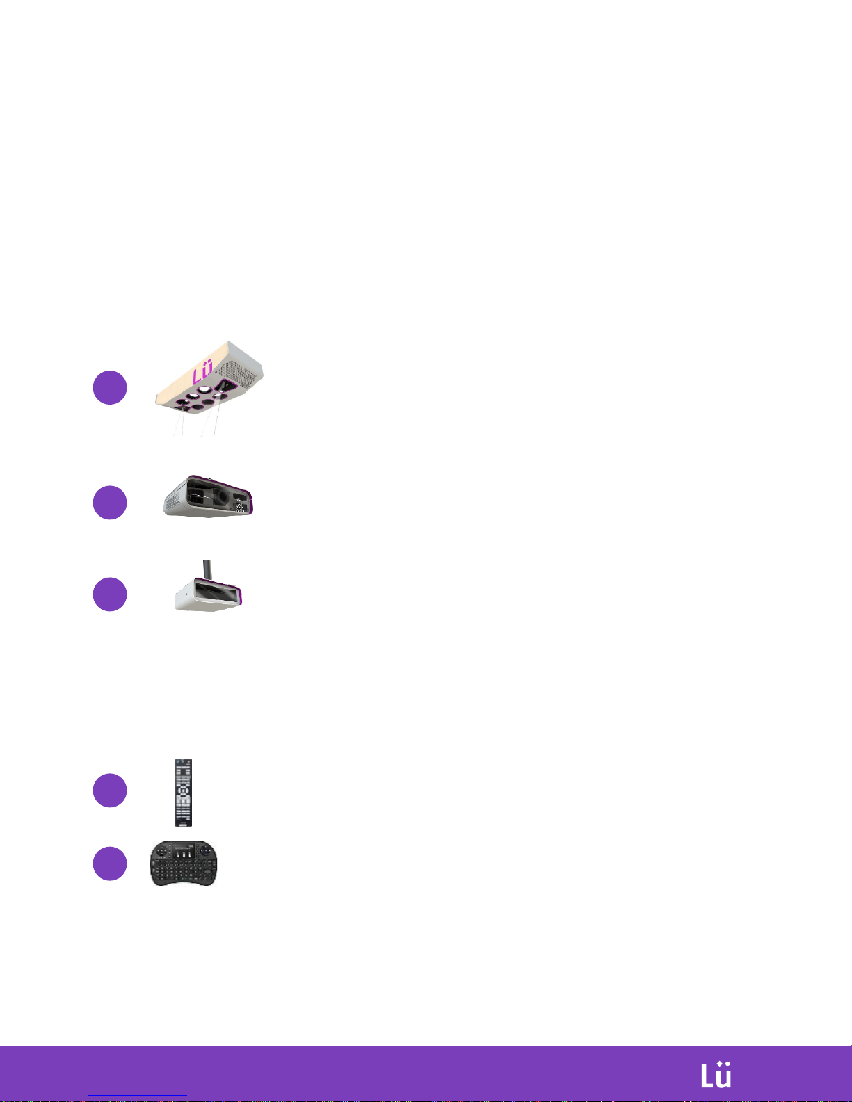
Product components
Each ÜNO configuration consist of (3) ceiling mounted modules:
Light & Sound Module
6x 200w LED PAR to manage the ambiant lighting
and general colors, 2x Robotised LED light fixtures
for special light effects and a powerful 2000 watts
sound system.
Projector Module
5500 lumens WXGA projector protected in a custom
enclosure
Camera Module
3D camera system.
And (2) remote controllers in a transport case:
1x Projector’s remote controller
INTERACTIVE
PLAYGROUND
1
2
3
1x Lü system remote controller
4
5
Page 5
ÜNO vs DÜO
INTERACTIVE
PLAYGROUND
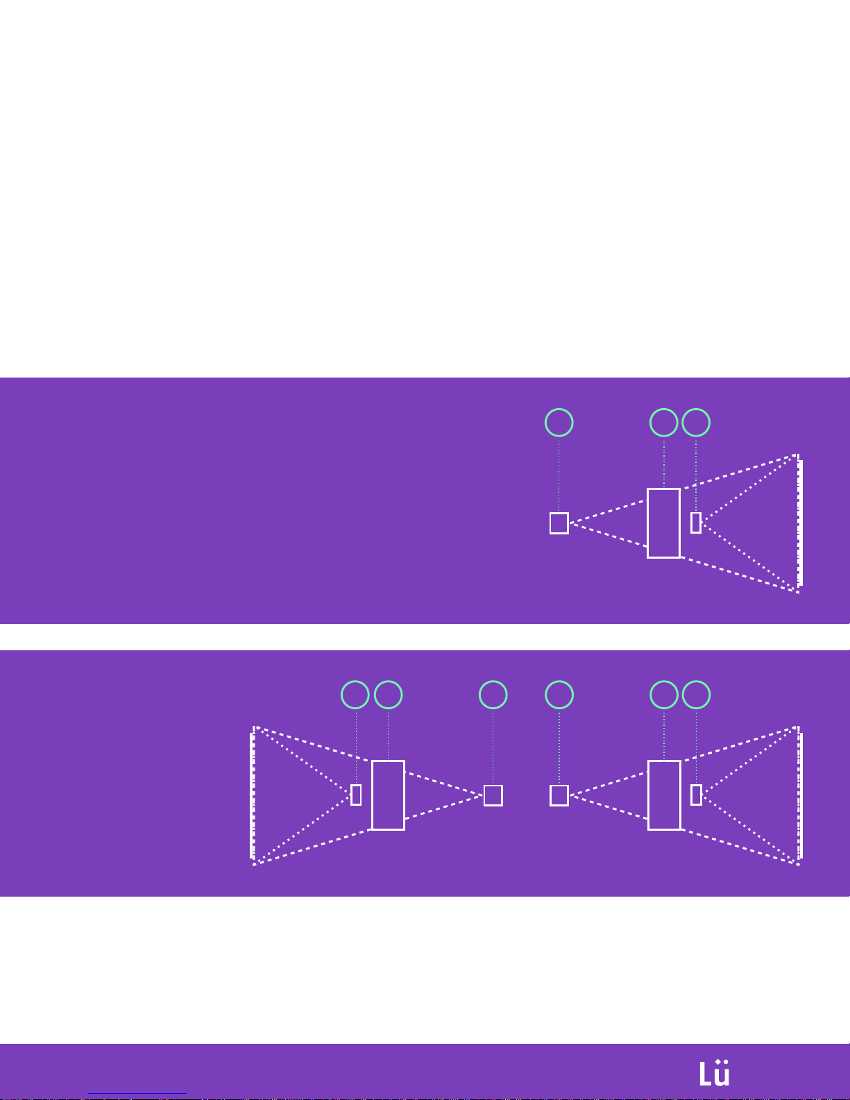
Installation configuration
Lü can be sold in two different configurations. ÜNO is one interactive wall. DÜO
is two interactive walls facing each other. DÜO is the equivalent to having two
ÜNO configurations, with some minor tweaks to allow synced experiences using
the full gymnasium
ÜNO
132
DÜO
13221
3
Page 6
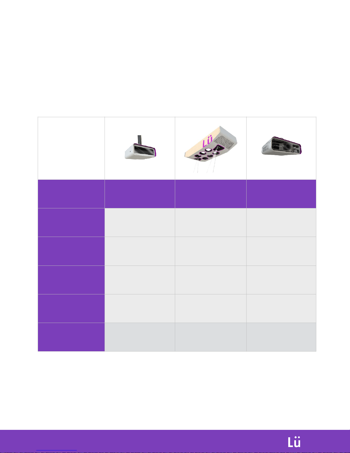
Technical Specifications
INTERACTIVE
PLAYGROUND
d
d
d
d
d
d
d
CAMERA MODULE
LIGHT & SOUND
MODULE
PROJECTOR
MODULE
INSTALLATION
POSITION*
16’ from the wall / 18’
high
18’ from the wall / 20’
high
30’ from the wall / 18’
high
SIZE
12’’ L x 12’’ L x 8’’ H
33’’ L x 84’’ L x 20’’ H
22’’ L x 20’’ L x 10’’ H
WEIGHT
5kg
125 kg
15 kg
RIGGING
1 1/2-11.5 NPS
THREADED FITTING
4 Hanging Points
(+2 rig points for
installation)
1 1/2-11.5 NPS
THREADED FITTING
POWER
CONSUMPTION
100-240V - 75W
100-240V - 1000W
100-240V - 462W
* Installation positions are optimal positions, but can be adapted to
different spaces when required. Contact us for more details.
Page 7
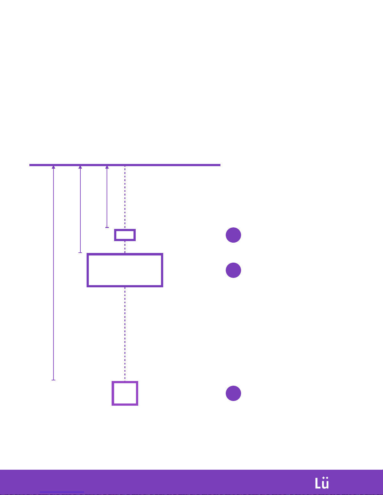
Installation configuration
All units are to be ceiling mounted, aligned on the projection surface like the
diagram below. Some exceptions for special environments can be made, please
contact us for more options.
INTERACTIVE
PLAYGROUND
1
2
3
Light & Sound Module
Install at 20’ (6m) from the floor
Must have 3’ (1m) clearance over
the unit for maintenance
Projector Module
Install at 20’ (6m) from the floor
Camera Module
Install at 18’ (5.5m) from the floor
Projection surface
Max: 19’ Large (5.8m) - 10’ High (3.3m)
D: 16’ (4.9m)
D: 18’ (5.5m)
D: 30’ (9.1m)
Top view
Page 8
INTERACTIVE
PLAYGROUND
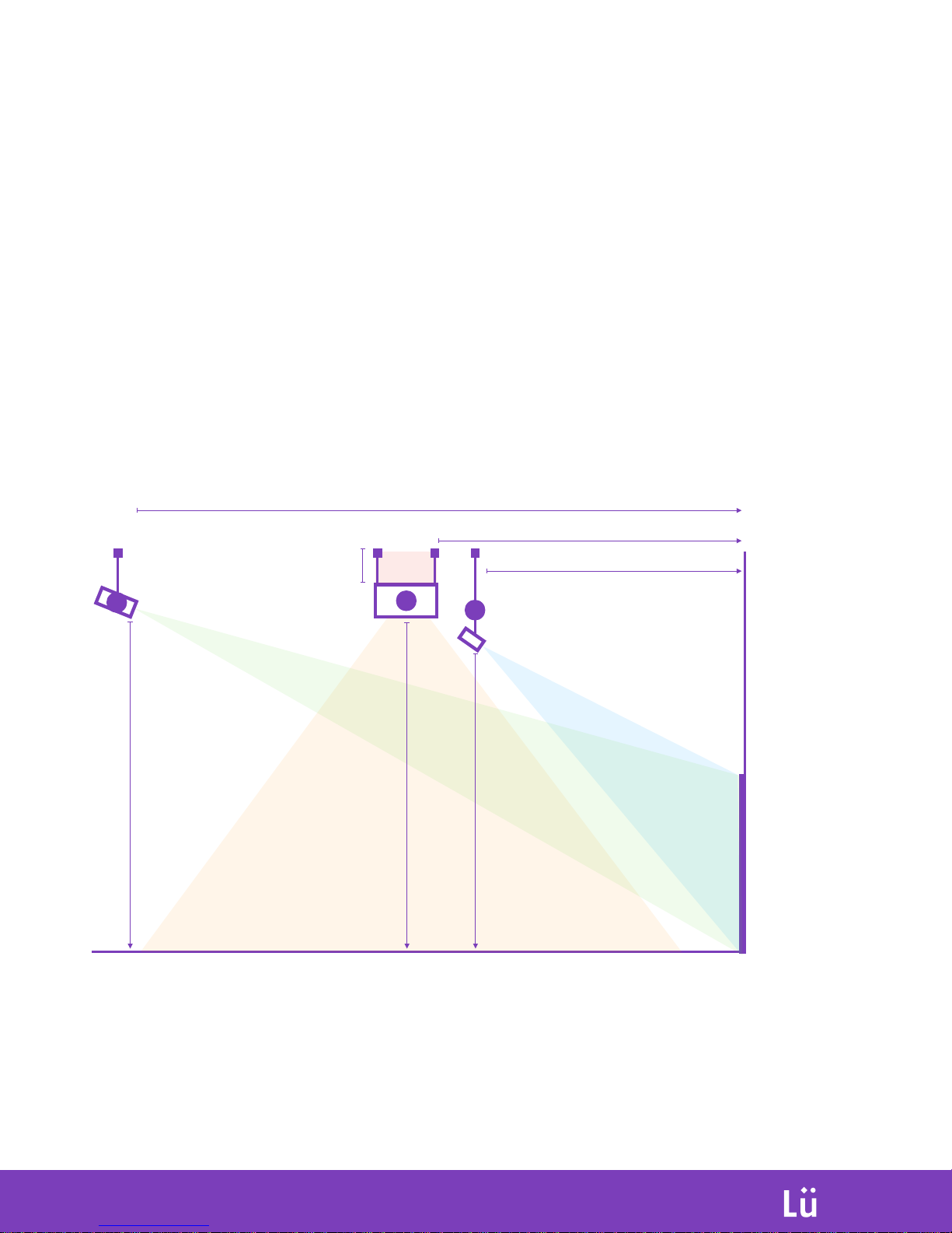
D: 16’ (4.9m)
D: 18’ (5.5m)
D: 30’ (9.1m)
H: 20’ (6m)
H: 20’ (6m)
H: 18’ (5.5m)
H: 3’ (1m)
Installation configuration
All units are to be ceiling mounted, aligned on the projection surface like the
diagram below. Some exceptions for special environments can be made, please
contact us for more options.
Side view
3
Projection max surface:
19’ Large (5.8m)
10’ High (3.3m)
1
2
Page 9
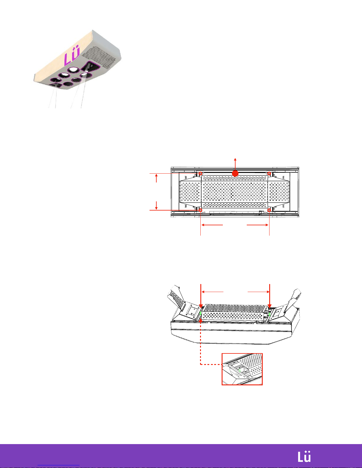
Light Module
Installation - Rigging
INTERACTIVE
PLAYGROUND
To be ceiling mounted using
the 4 rig points located on
the main frame.
45 inches
24 inches
To facilitate lifting using a hoister
from floor to ceiling, we included
two eyebolt centred on the unit.
Size of holes: 1/2’’ (15mm)
Lifting Eyebolts
Mount unit with side ‘’A’’
facing toward the interactive
projection wall.
A
Page 10
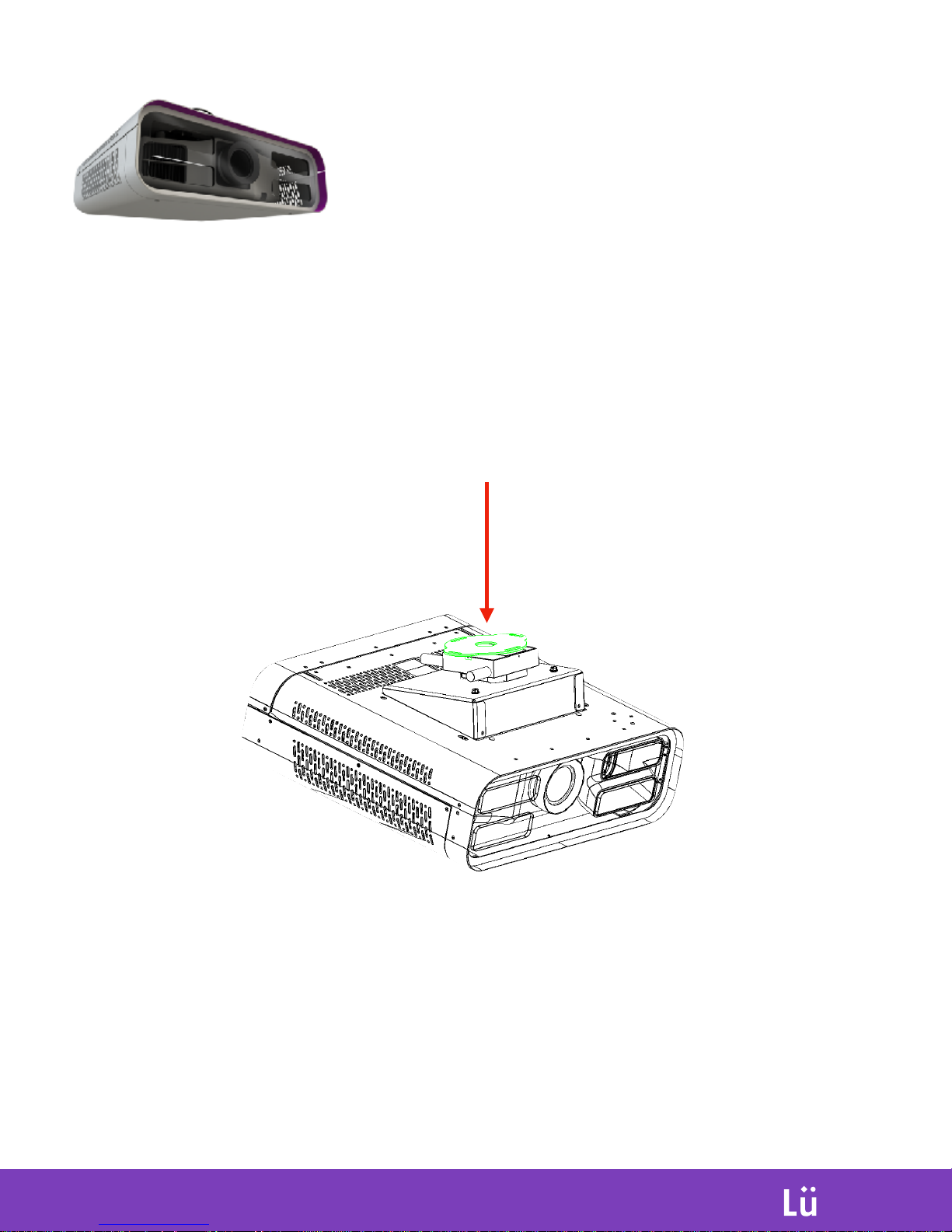
Projection Module
Installation - Rigging
INTERACTIVE
PLAYGROUND
To be ceiling mounted
using a pole with 1 1/2-11.5
NPS THREADED FITTING
Page 11
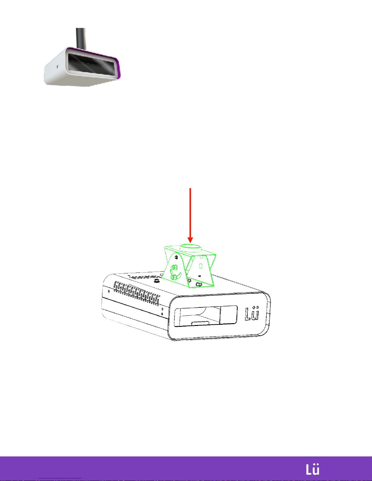
Camera Module
Installation - Rigging
INTERACTIVE
PLAYGROUND
To be ceiling mounted
using a pole with 1 1/2-11.5
NPS THREADED FITTING
Page 12
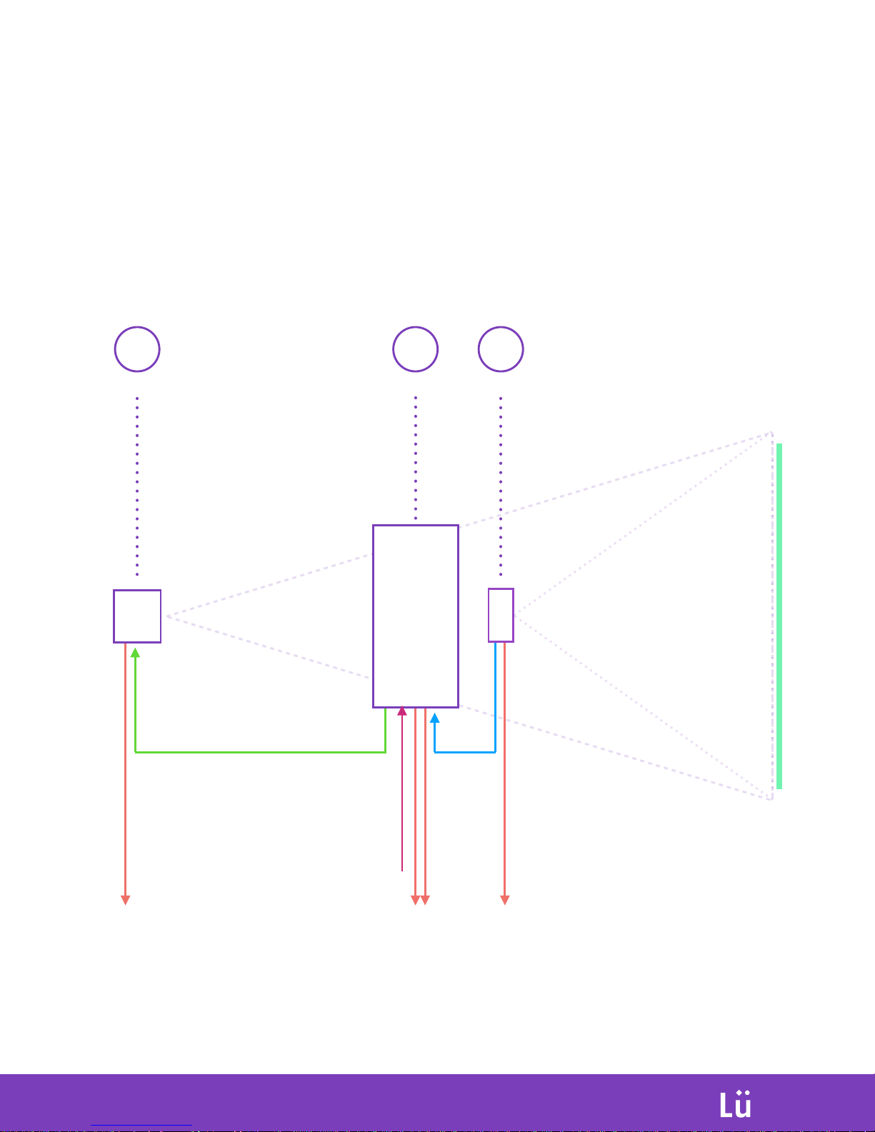
ÜNO - Connection diagram
Operation
INTERACTIVE
PLAYGROUND
132
USB3 from
camera to
NUC PC
HDMI from
NUC PC to
projector
Power to
ceiling QUAD
outlets
Connect modules 1, 2 and 3 following this diagram with provided cables
Wired internet connection
from NUC PC to ceiling
mounted network outlet
Power to
ceiling QUAD
outlets
Power to
ceiling QUAD
outlets
Page 13
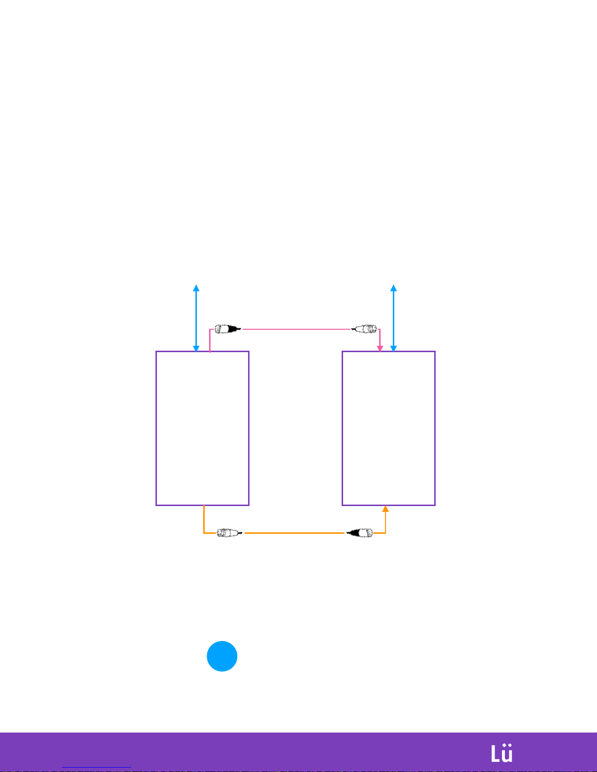
DÜO - Connection diagram
Operation
INTERACTIVE
PLAYGROUND
1. Connect modules 1, 2 and 3 using the ÜNO connection diagram
2. Inter-connect the two light modules together following this diagram
D1 - Light module
D2 - Light module
Master unit
Slave unit
DMX
DMX output #2 from DATA
STREAM to LED PAR #085 input
ETHERNET
Ethernet cable from D1 NUC PC to ceiling
outlet provided by customer*
XLR AUDIO
LEFT Output from NUC PC to
INPUT 2 on D2-S1 SPEAKER
ETHERNET
Ethernet cable from D2 NUC PC to ceiling
outlet provided by customer*
The two computers must be on the same
network for the DÜO system to work. Only
one DÜO system per network.
!
Page 14
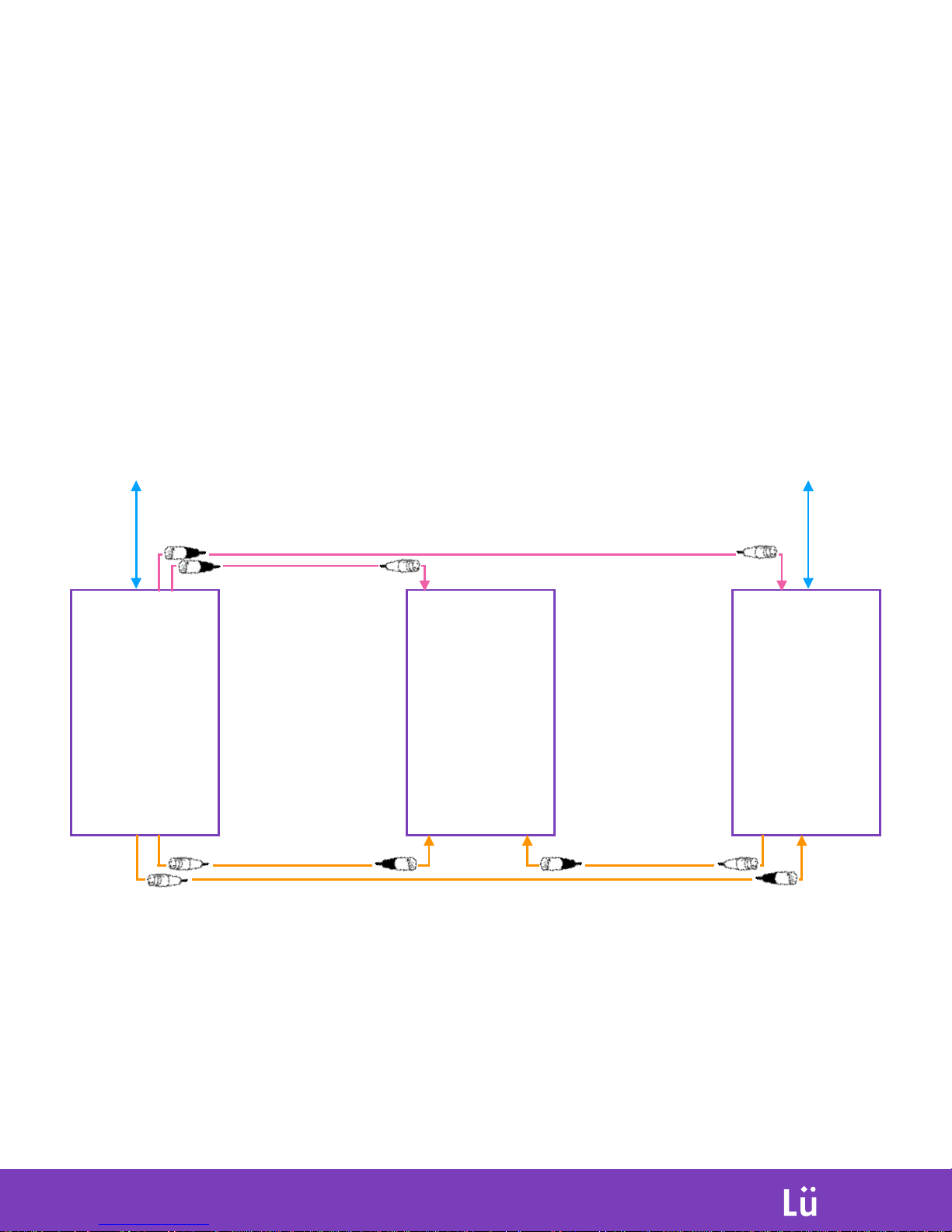
DÜO with extra lighting unit - Connection diagram
Operation
INTERACTIVE
PLAYGROUND
1. Connect modules 1, 2 and 3 using the ÜNO connection diagram
2. Inter-connect the two light modules together following this diagram
D1 - Light module
D2 - Light module
Master unit
Slave unit
DMX
DMX output #2 from DATA
STREAM to LED PAR #085 input
D3 - Light module
Extra unit
DMX
DMX output #3 from DATA
STREAM to LED PAR #109 input
XLR AUDIO
Output from D1-S2 SPEAKER
to INPUT 1 on D3-S1 SPEAKER
XLR AUDIO
Output from D2-S2 SPEAKER to
INPUT 2 on D3-S1 SPEAKER
XLR AUDIO
LEFT Output from NUC PC to
INPUT 2 on D2-S1 SPEAKER
ETHERNET
Ethernet cable from D1 NUC PC to ceiling
outlet provided by customer*
ETHERNET
Ethernet cable from D2 NUC PC to ceiling
outlet provided by customer*
Page 15
Operation
INTERACTIVE
PLAYGROUND
Site and screen preparation
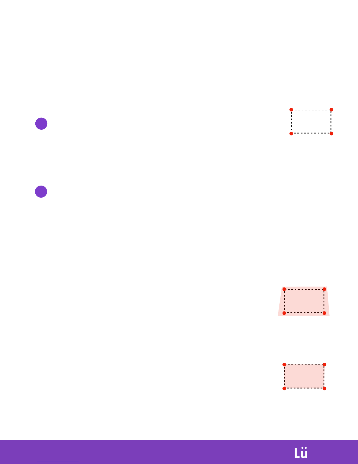
Mark the (4) corners of your projection location on the wall
Ideal position is to set the bottom of the screen at 1 feet (30cm) from the floor.
Maximum Width of 19’ (5,8m), height of 10,68 feet (3,25m).
***Always respect a ratio of 16:9 for your screen.
1
2
Focus projector into position
Image should easily cover the 4 markers on the wall
with an extra 10’’ (25cm) from the closest markers.
This extra room will allow user to reposition projector
over time without having to access physically the
projector.
D. Map projected image on your 4 markers using digital 4
corner image distortion. (GEOMETRY BUTTON / 4 CORNERS)
**Make sure the projector is turned on, on the right input (you should see Lü interface
from the computer), and the aspect ratio of the projector should be on FULL.
A. Using projector’s lens shift adjustment, lower the
image to the maximum position.
B. Adjust focus and zoom to get optimal size using
projector lens
C. Position image over the 4 markers using mounting
bracket adjustments and fine-tune size by adjusting
zoom and focus and the same time.
Page 16
System Calibration
Operation
INTERACTIVE
PLAYGROUND
When all components are rigged, and connected, you are ready for calibration.
Camera calibration
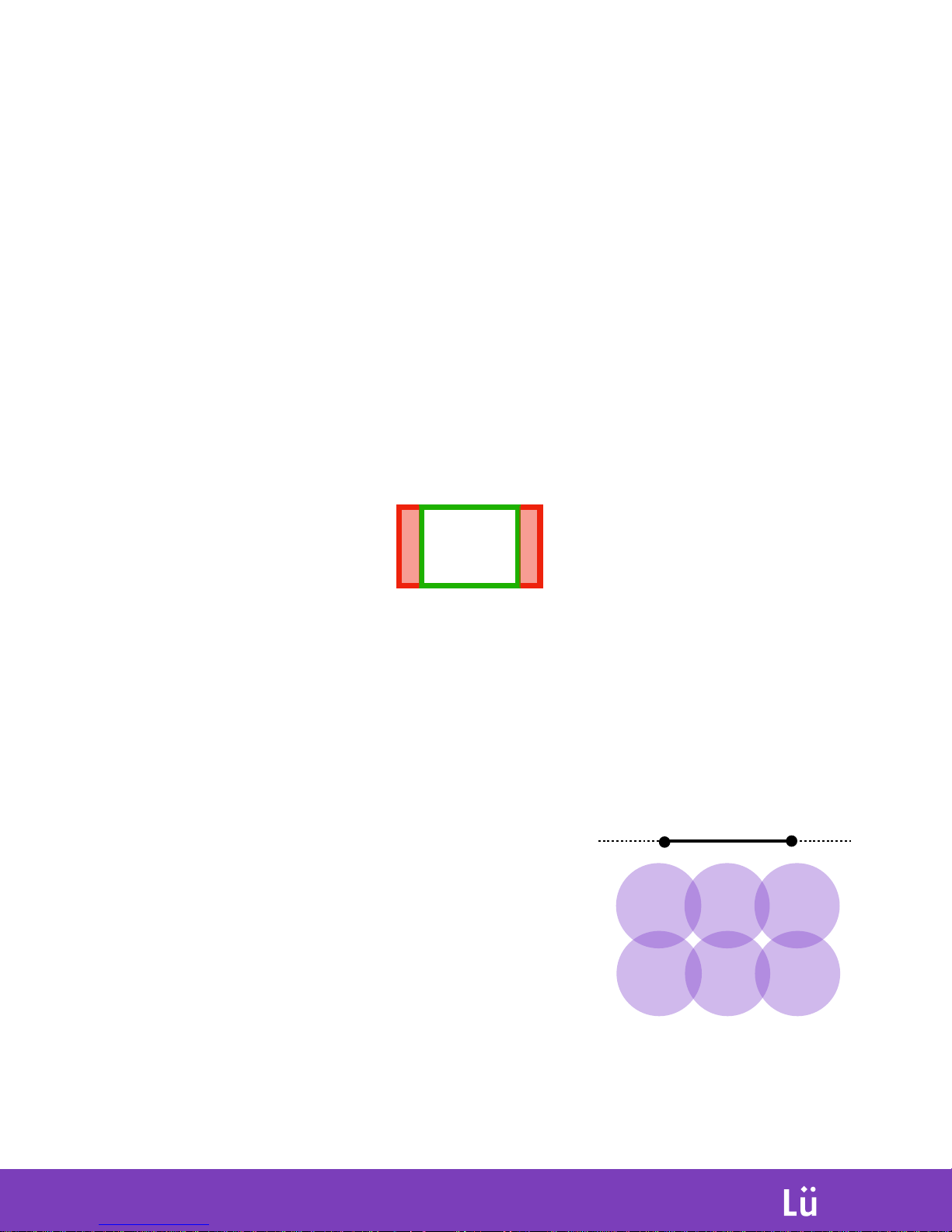
In the Lü main menu, hit the gear shortcut in the main menu and enter camera calibration. On the purple
background interface, hit the ‘’V’’ key on the keyboard to display the camera feed from the kinect, and
adjust camera position to center the projection area in the RGB field of view from the camera. Please
consider the image of the projection has to be in the 4:3 ratio of the displayed image:
When camera is in final position, hit ‘’ESC’’ key on keyboard two times to exit advanced calibration, and
click on the ‘’CALIBRATE’’
Lock the 1.5’’ pipe with self drilling screw on two ends.
Lock the camera tilt adaptor using a self drilling screw.
Lights calibration
Adjust all 6 LED PAR positions to optimize the floor
space covered by the light beams. The hot spots
from the first row of light beam must be at least
8’ (2.4m) from the projection wall.
Reference for camera positioning:
Page 17
B. Click on the button.
Camera Calibration
Calibration will adjust the camera used to detect balls on the wall. Once the system is
calibrated, it is not necessary to repeat the operation each time. The system should only be
calibrated when you feel that the contact between the ball and the wall is not accurate. To
calibrate the system, follow the steps below:
Operation
INTERACTIVE
PLAYGROUND
A. Select the button in the settings ( ) menu.
C.
D. Press “Esc” and “Enter” to return to the homepage.
Throw a ball into the white section to confirm that the
contact of the ball on the wall is now adjusted.
While the system is calibrating, a calibration grid will appear and after a few
seconds the message “Calibration Successful” will display.
E.
Page 18
INTERACTIVE
PLAYGROUND
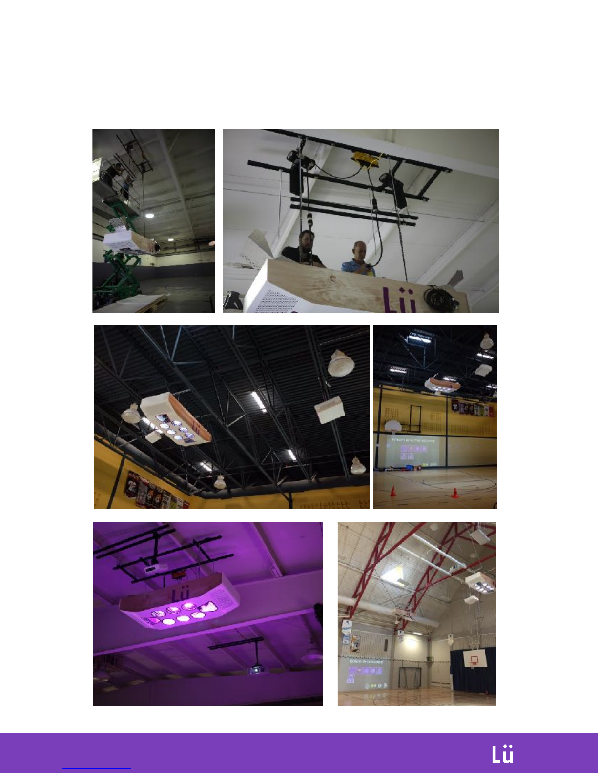
Installation exemples
Page 19

Complete components documentation
For more detailed informations about some selected Lü
interactive playground components:
Video projector - Epson 5520w projector
https://files.support.epson.com/docid/cpd5/cpd52631.pdf
Loudspeakers - Electro-Voice ZLX 12P
http://www.electrovoice.com/binary/ZLX_F01U319253_en.pdf
PC Computer - Intel NUC
https://www.intel.com/content/www/us/en/products/boardskits/nuc/kits/nuc6i5syh.html
DMX Distribution - Chauvet Data Stream 4
https://www.chauvetdj.com/wp-content/uploads/2015/12/
Data_Stream_4_UM_Rev2_WO-1.pdf
Wireless microphone - Shure BLX14R
http://pubs.shure.com/guide/BLX4R/en-US
INTERACTIVE
PLAYGROUND
Contact informations
For support, any questions or comment on this product:
+1 418 781-0797
[email protected]
202-707 St-Vallier E. St
Quebec, QC, Canada
G1K 3P9
 Loading...