

Page 1
00P677280ZSEB3
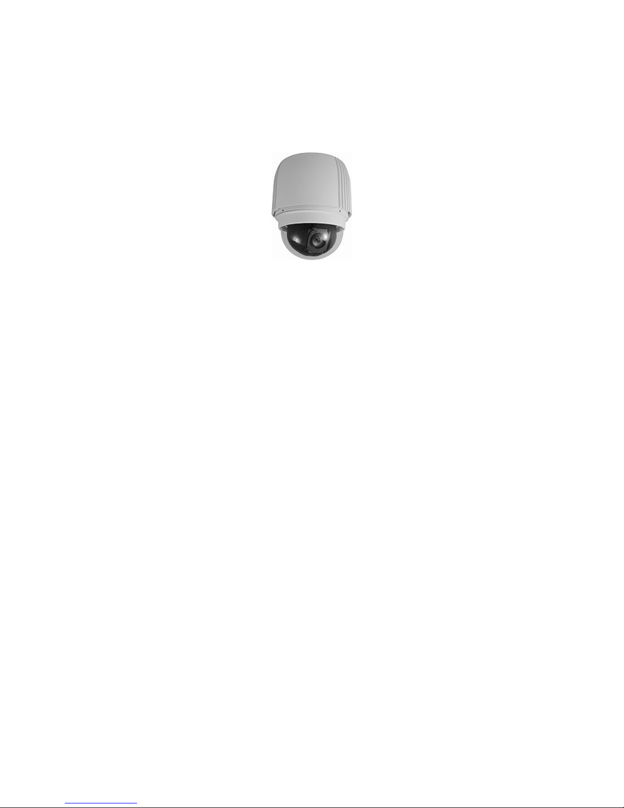
Integrated High Speed Dome Camera
Outdoor Dome
Installation Guide
Version 1.3
Page 2
Installation Guide
1
Preface
Information given in this manual was current when published. The company reserves the
right to revise and improve its products. All specifications are subject to change without
notice.
Notice
This manual provides installation information for the outdoor integrated high
speed dome. To work with the dome cameras, any installer or technician
must have the following minimum qualifications:
• A basic knowledge of CCTV systems and components
• A basic knowledge of electrical wiring and low-voltage electrical
hookups
• Have read this manual completely
Copyright
Under copyright laws, the contents of this installation guide may not be copied,
photocopied, translated, reproduced or reduced to any electronic medium or
machine-readable format, in whole or in part, without prior written permission
of the company.
Important Information
Before proceeding, please read and observe all instructions and warnings in
this manual. Retain this manual with the original bill of sale for future
reference and, if necessary, warranty service. When unpacking your unit,
check for missing or damaged items. If any item is missing, or if damage is
evident, DO NOT INSTALL OR OPERATE THIS PRODUCT. Contact your
dealer for assistance.
Regulation
This device complies with Part 15 of the FCC Rules.
Operation is subject to the following two conditions:
(1) this device may not cause harmful interference, and (2)
this device must accept any interference received, including
interference that may cause undesired operation.
Page 3
Installation Guide
2
This symbol on the product or on its packaging indicates
that this product shall not be treated as household waste in
accordance with Directive 2002/96/EC. Instead it shall be
handed over to the applicable collection point for the
recycling of electrical and electronic equipment. By proper
waste handling of this product you ensure that it has no
negative consequences for the environment and human
health, which could otherwise be caused if this product is
thrown into the garbage bin. The recycling of materials will
help to conserve natural resources.
For more details information about recycling of this product,
please contact your local city office, your household waste
disposal service or the shop where you purchased the
product.
Compliance is evidenced by written declaration from our
suppliers, assuring that any potential trace contamination
levels of restricted substances are below the maximum
level set by EU Directive 2002/95/EC, or are exempted due
to their application.
Page 4
Installation Guide
3
Warnings and Cautions
• Handle the camera carefully
Do not abuse the camera. Avoid striking, shaking, etc. The camera could
be damaged by improper handing or storage.
• Installing electricity wiring carefully
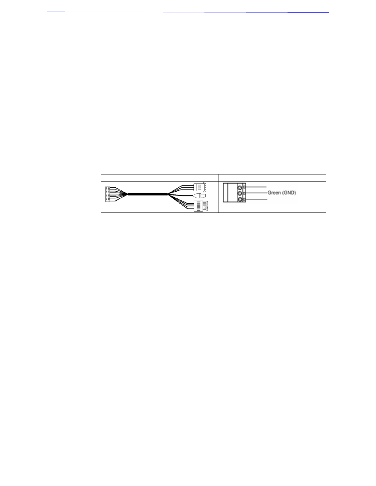
Ask qualified personnel of electrical wiring for the installation. Please note
that input electricity to the unit is at tolerance of DC12V/AC24V ± 10%.
The camera is capable of surge protection; ensure AC power model unit
grounded appropriately against damage of heavy current or electric
shock.
Refer to the camera’s installation guide for more information.
AC model data cable AC power input: 3-pin terminal block
• Do not disassemble the camera
To prevent electric shock, do not remove screws or covers. There are no
user serviceable parts inside. Ask a qualified service person for servicing.
• Do not block cooling holes on the bracket
This camera has a cooling fan inside. Blocking the cooling holes leads to
build up of heat the camera and may cause malfunction.
• Do not operate the camera beyond the specified temperature,
humidity or power source ratings
Use the camera under conditions where temperature is between -35°C ~
50°C (-31°F ~ 122°F), and relative humidity is below 90%.
• Do not use strong or abrasive detergents when cleaning the camera
body
Use a dry cloth to clean the camera when it is dirty. In case the dirt is hard
to remove, use a mild detergent and wipe the camera gently.
• Never face the camera towards the sun
Do not aim the camera at bright objects. Whether the camera is in use or
not, never aim it at the sun or other extremely bright objects. Otherwise,
the camera may be smeared or damaged.
Page 5

Installation Guide
4
Table of Contents
1. Introduction................................................................................................................5
2. Standard Package Content.......................................................................................6
3. Dome Setups and Cable Connection.......................................................................7
3.1 Preparations for Dome Setups..........................................................................7
3.2 Dome Setups ....................................................................................................9
3.2.1 Switch Definition ..................................................................................9
3.2.2 Communication Switch Setting ..........................................................10
3.2.3 Dome ID Setting ................................................................................10
3.2.4 Dome Control Protocol Setting .......................................................... 11
3.3 Dome Cable Definition and Requirements ......................................................12
3.3.1 Cable Requirements ..........................................................................12
3.3.2 22-Pin Data Cable .............................................................................13
3.3.3 22-Pin Connector Definition...............................................................13
3.3.4 RS-485 Connector Definition .............................................................14
3.3.5 Cable Wiring and Connection ............................................................15
4. Dome Installation.....................................................................................................17
4.1 Dome Dimension.............................................................................................17
4.2 Optional Accessories.......................................................................................17
4.3 Ceiling Mounting with Straight Tube................................................................23
4.4 Wall Mount ......................................................................................................25
4.4.1 Wall Mounting with Gooseneck Tube.................................................25
4.4.2 Mini Pendant Mount...........................................................................26
4.4.3 Wall Box Mounting.............................................................................27
4.5 Corner Mount ..................................................................................................28
4.5.1 Corner Standard Mounting Plate .......................................................28
4.5.2 Corner Thin/Wide Box Mounting........................................................30
4.6 Pole Mount......................................................................................................31
4.6.1 Pole Thin/Wide Direct Mounting ........................................................31
4.6.2 Pole Thin/Wide Box Mounting............................................................32
5. System Expansion...................................................................................................34
5.1 Connecting with Power Box ............................................................................34
5.2 Data Formats Transforming.............................................................................35
5.3 Signal Distribution ...........................................................................................36
5.4 Coaxial Telemetry............................................................................................37
6. System Integration ..................................................................................................38
6.1 Using Pelco Keyboard.....................................................................................38
6.2
Using Philips Allegiant Keyboard.....................................................................39
Appendix A: Technical Specification .............................................................................40
Page 6
Installation Guide
5
1. Introduction
With weather resistant feature, the Integrated High Speed Dome Camera is
applicable to outdoor installation. The dome camera supports one cabling for
easy installation, and can be integrated with CCTV products, such as DVRs,
Control Keyboards, and CCTV accessories for a total surveillance solution. In
addition, large set of built-in protocols provide connectivity to other
surveillance systems. The built-in protocols include DynaColor, Pelco, VCL,
Philips, AD-422 (Manchester), etc., which allow the Integrated High Speed
Dome Camera to be integrated with other suppliers' surveillance systems.
General Operation Requirements:
A minimum of one control device is required for operation, such as a control
keyboard, a DVR or a PC. The integrated high speed dome camera contains
a built-in receiver that decodes commands from a control device.
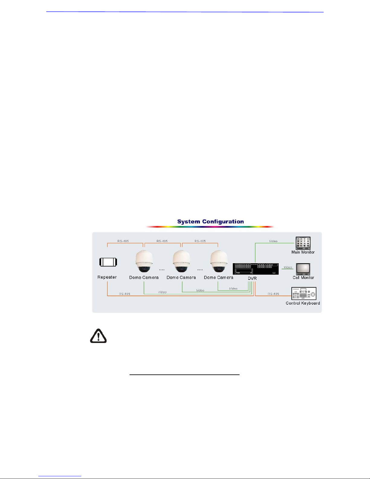
Connect dome cameras to other devices, as shown in the diagram below, to
complete a video surveillance system.
NOTE: To extend the network distance up to 1.2 km (4000 feet) and to
protect the connected devices, it is highly recommended to place a
repeater at the mid-point. However, a repeater may be needed in the network
distance less than 1.2 km if the used cables are not the CAT 5, 24-gauge
cables (see 3.3.4 RS-485 Connector Definition). Refer to the repeater’s
manual for detailed information.
Page 7
Installation Guide
6
2. Standard Package Content
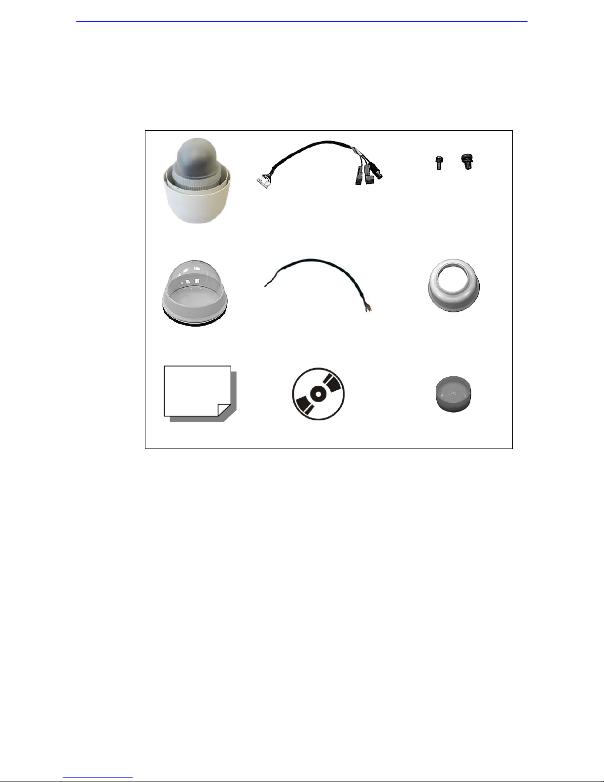
Before proceeding, please check the box contains the items listed here. If any
item is missing or has defects, DO NOT install or operate the product and
contact your dealer for assistance.
Dome Body
50-cm Data Cable for power
supply, video and telemetry
Screws
Optical Cover
50-cm, 13-pin Alarm Cable
Waterproof rubber
Quick Guide
CD: Operation Manuals
Lubricant
Page 8
Installation Guide
7
3. Dome Setups and Cable Connection
Before installing or connecting the dome camera, please refer to this section
and complete preparations for dome setups and various switch settings.
3.1 Preparations for Dome Setups
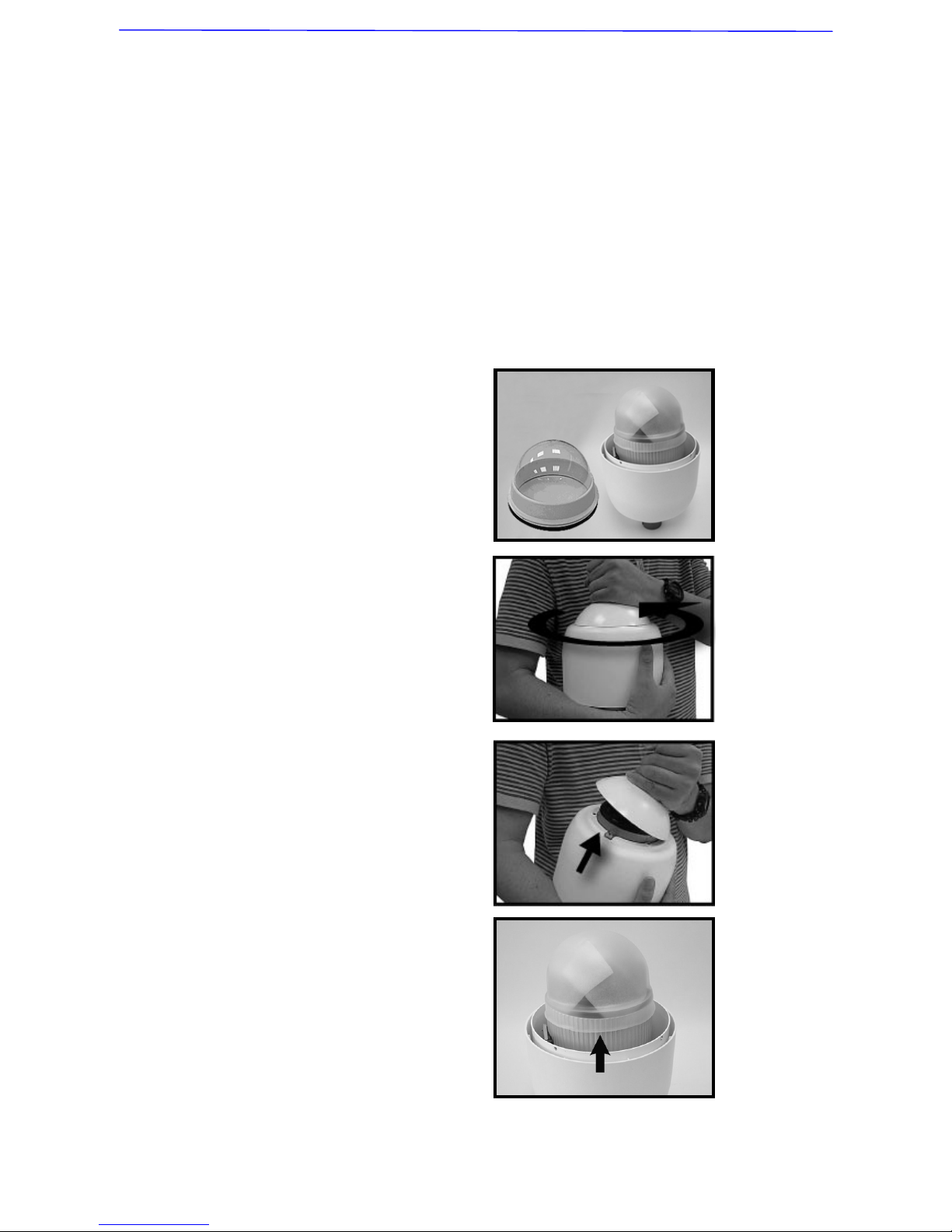
The following installation procedure is for the outdoor dome equipped with the
sunshield housing. Please follow the steps below to complete dome housing
installation.
STEP 1
Unpack the dome package and
take out the dome body.
STEP 2
Rotate the top holder and take
it off from the dome body.
STEP 3
Remove the protective cover
and PE sheet.
Page 9
Installation Guide
8
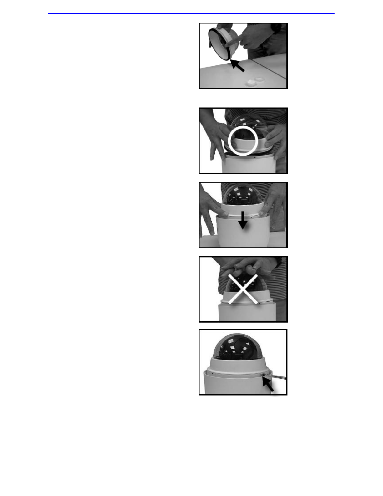
STEP 4
Attach the dome cover to the
dome body. Before doing that,
apply some lubricant on the
cover’s water-proof rubber to
make the installation process
smoother.
Note that the tiny protrusion on
the dome cover must align with
one of the four holes on the
dome body.
STEP 5
Gently pressure the dome
cover downward with two
hands on the side of it.
DO NOT press the cover, as
shown in the figure; this might
cause damage to the dome
body.
STEP 6
Screw the dome cover and
body together.
Page 10
Installation Guide
9
STEP 7
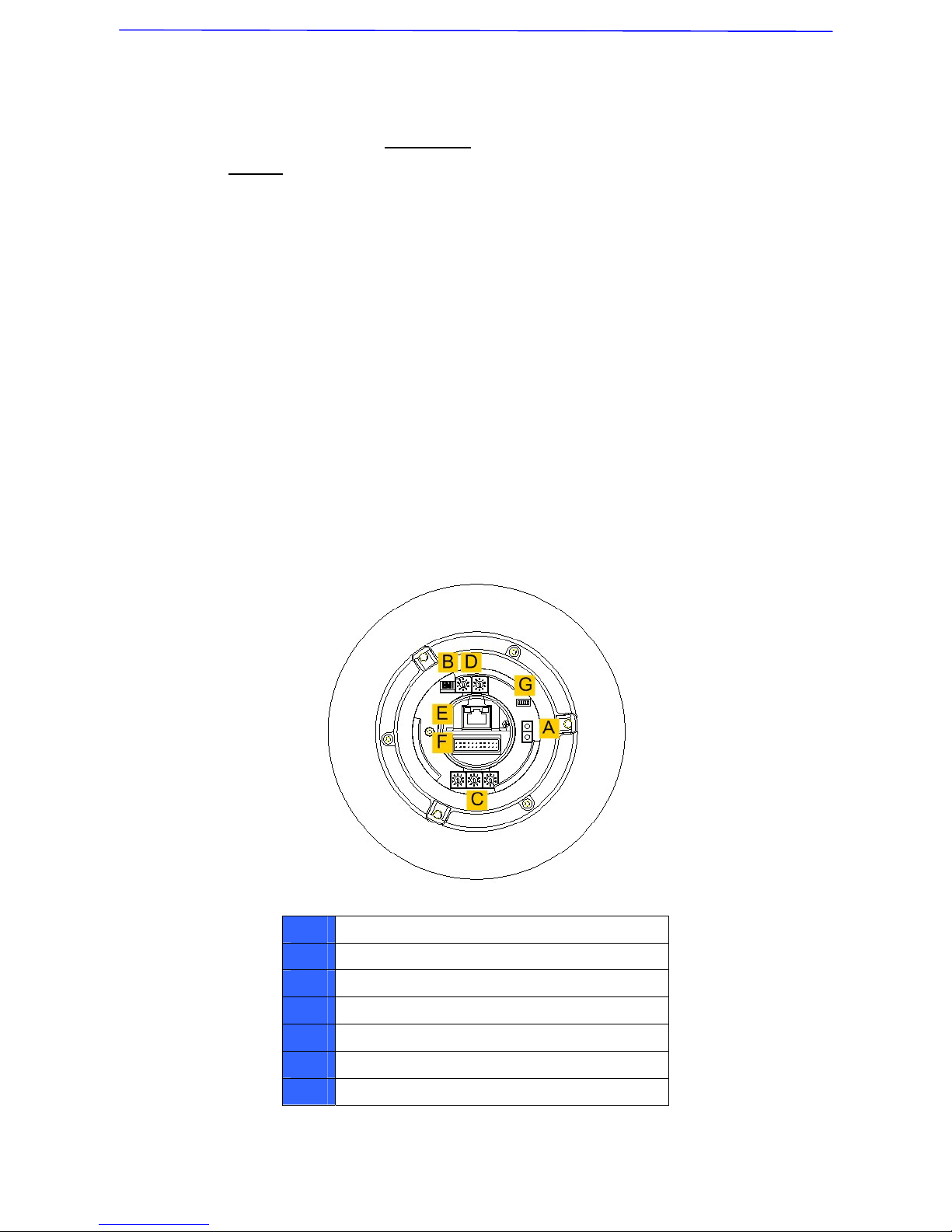
Set the switches located on the
bottom of the dome body.
Refer to section 3.2 Dome
Setups for detailed information
about various switch setting.
3.2 Dome Setups
Before connecting the dome camera to other devices of CCTV system,
please complete the dome ID and communication switch settings. These
switches are located on the bottom of the dome camera.
3.2.1 Switch Definition
Please refer to the following figure and table for switch location and
definitions.
A
Reserved
B
Communication Switch
C
Dome ID Switch
D
Dome Control Protocol Switch
E
RJ-45 Connector (for IP Dome only)
F
22-Pin Connector
G
ISP Connector (for FW upgrade)
Page 11
Installation Guide
10
3.2.2 Communication Switch Setting
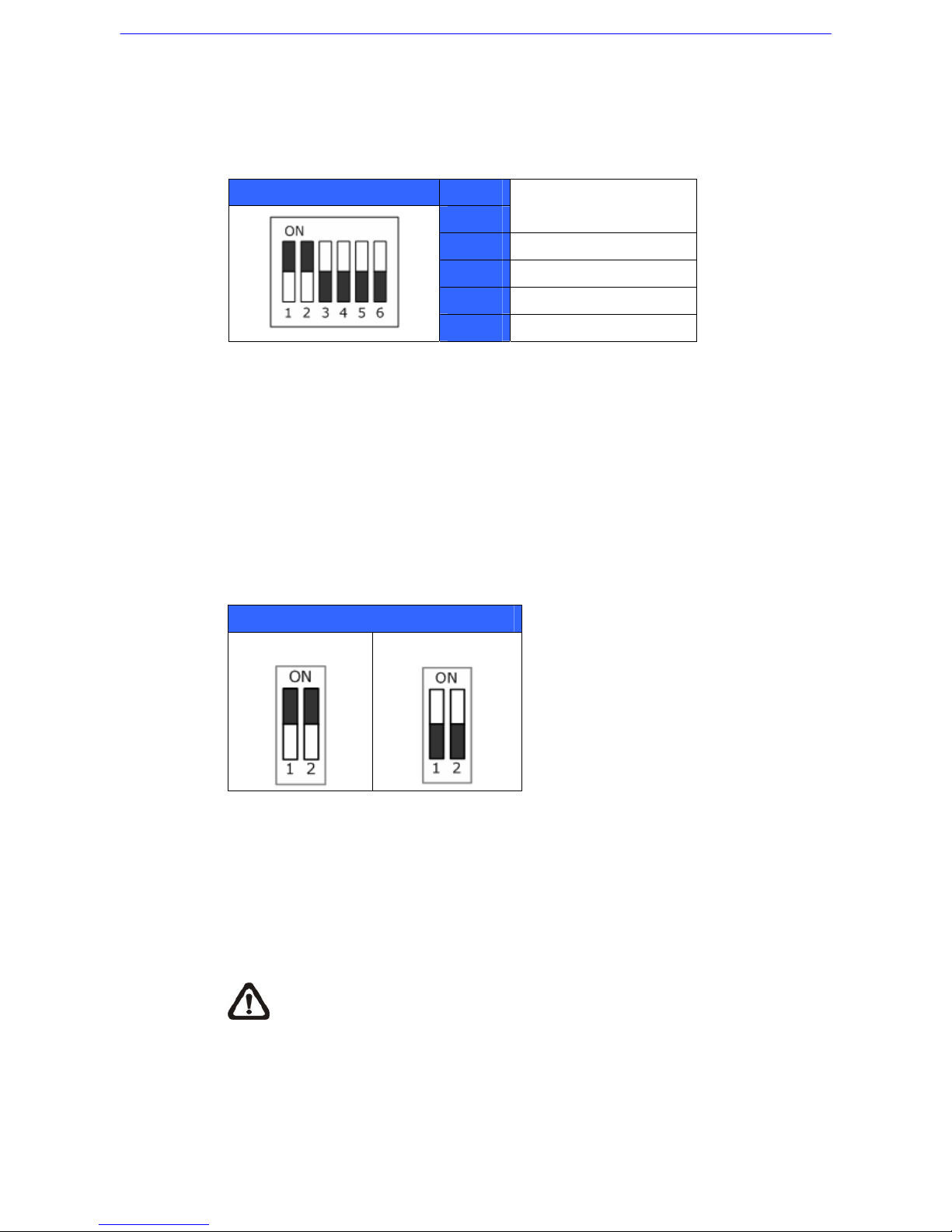
The table below shows the function of each switch within the Communication
Switch.
Communication Switch SW 1
SW 2
RS-485 Setting
SW 3
Termination
SW 4
Line Lock
SW 5
System Initialization
SW 6
Reserved
RS-485 is the interface that communicates the dome camera and its control
device; for this reason, the RS-485 setup of the dome and the control device
must be the same. The RS-485 default setting is half-duplex (see the diagram
follows). Please do not change the default setting without qualified specialist
or supplier’s notice. As for the SW 3 and SW 4, they are used for termination
and Line Lock adjustment respectively. The SW 5 is mainly used when users
want to restore the camera to the factory default status; moreover, once
firmware upgrade is carried out, users also need to reset the SW 5 afterward.
RS-485 Setting
Half-duplex
Full-duplex
3.2.3 Dome ID Setting
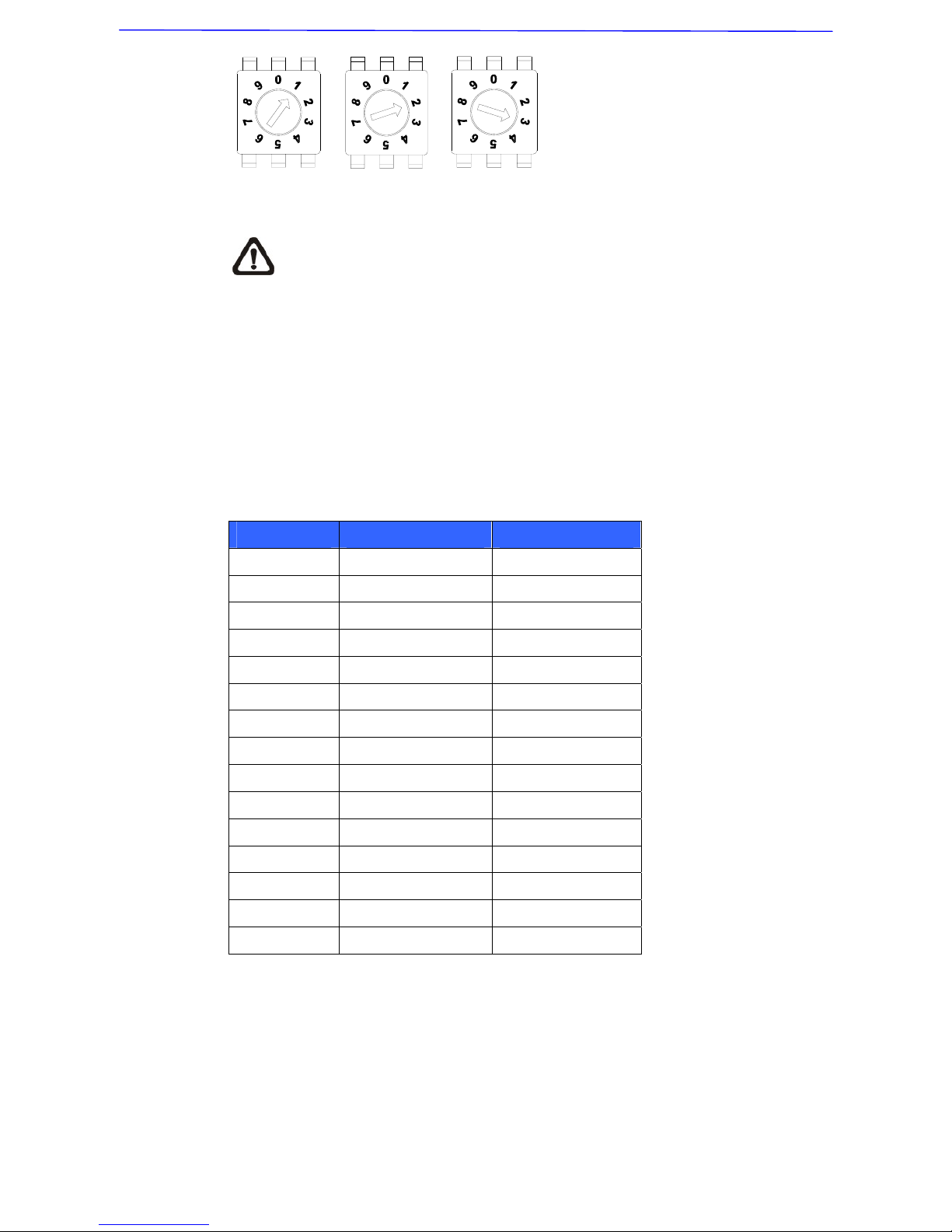
Use the switch to change your speed dome ID by turning the arrow to the
desired number respectively. For instance, if the dome ID is 123, the ID switch
should be set as below.
NOTE: No two domes should be given the same ID, or communication
conflict may occur.
Page 12
Installation Guide
11
Centesimal Digit Decimal Digit Single Digit
NOTE: The number “0” should locate upwards as shown in above
diagram for correct switch definition.
3.2.4 Dome Control Protocol Setting
Define the protocol you are going to use basing on the devices of your
surveillance system. Generally, use one protocol even the devices are
provided from different manufacturers. Use the switch to set your dome
control protocol and the baud rate. Refer to the table below and turn the
arrow to choose a protocol for your speed dome.
Switch No. Protocol Baud Rate
00
VCL 9600
01
Pelco D 2400
02
Pelco P 4800
04
Chiper 9600
05
Philips 9600
07
DSCP 9600
08
AD422 4800
09
DM P 9600
11
Pelco D 4800
12
Pelco D 9600
13
Pelco P 2400
14
Pelco P 9600
15
JVC 9600
21
Kalatel-485 9600
22
Kalatel-422 4800
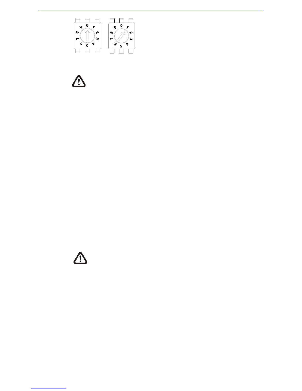
Select protocol: Pelco D, with switch no. 01 and baud rate 2400, for instance,
the protocol switch should be set as below.
Page 13
Installation Guide
12
Decimal Digit Single Digit
NOTE: The number “0” should locate upwards as shown in above
diagram for correct switch definition.
3.3 Dome Cable Definition and Requirements
For operation, the integrated dome camera requires the video cable to carry
the video signals to the remote viewing site, power cable to power the dome
and RS-485 data cable to carry commands from the control device.
3.3.1 Cable Requirements
For operation, the integrated high speed dome cameras require video and
data cables as described below:
• The video cable sends video signals to a remote viewing site. Using a
coaxial cable to send video signals is recommended.
• RS-485 cable carries commands from a control device to the dome
cameras. A CAT 5, 24 gauge cable is recommended.
• The power cable provides AC 24V power supply to the dome.
NOTE: Ensure power supply corresponds with the dome’s power
requirement, or product impairment will occur. If any mistake happens,
please contact with a qualified maintenance engineer.
Page 14
Installation Guide
13
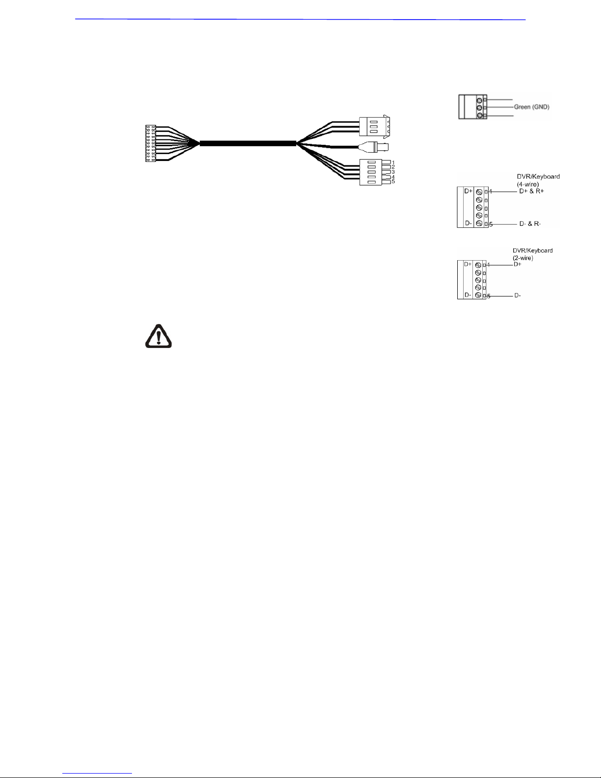
3.3.2 22-Pin Data Cable
Power
Input
3-Pin Terminal Block
Video
Output
BNC connector
RS485
Connector
4-wire
2-Wire
NOTE: Be careful not to pull the cables improperly during installation.
Additionally, it is suggested to fasten the cables after cable connection
is completed. Furthermore, when wiring the power cable, make sure
the G/Y wire (Ground) inserted into the mid-pin of the terminal block.
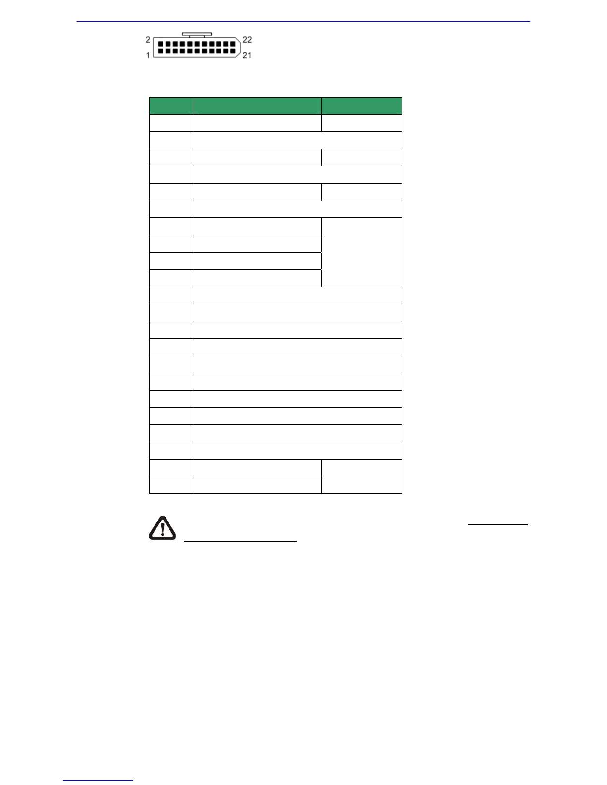
3.3.3 22-Pin Connector Definition
With the 22-pin connector, installers can simply connect the power, video and
RS-485 cables to the dome at once. Particularly, the alarm pins are
serviceable for connecting alarm input and output devices, such as alarm
sensors, sirens or flashing lights with the surveillance system. For the
definition of each pin, please refer to the list below.
Page 15
Installation Guide
14
The 22-pin connector definition is listed as below.
Pin Definition Cable
1
AC 24-1/DC (+)
20AWG
2
ALM NC
3
AC 24-2/DC (-)
20AWG
4
ALM NO
5
FG 20AWG
6
ALM COM
7
T+
8
R-
9
T-
10
R+
24AWG
11
ISOG
12
ALM-1
13
ALM-3
14
ALM-2
15
ALM-4
16
ALM-5
17
ALM-6
18
ALM-7
19
ALM-8
20
ALM GND
21
VGND
22
Video
24AWG
NOTE: For alarm connection, please refer to section 3.3.5 Cable
Wiring and Connection
.
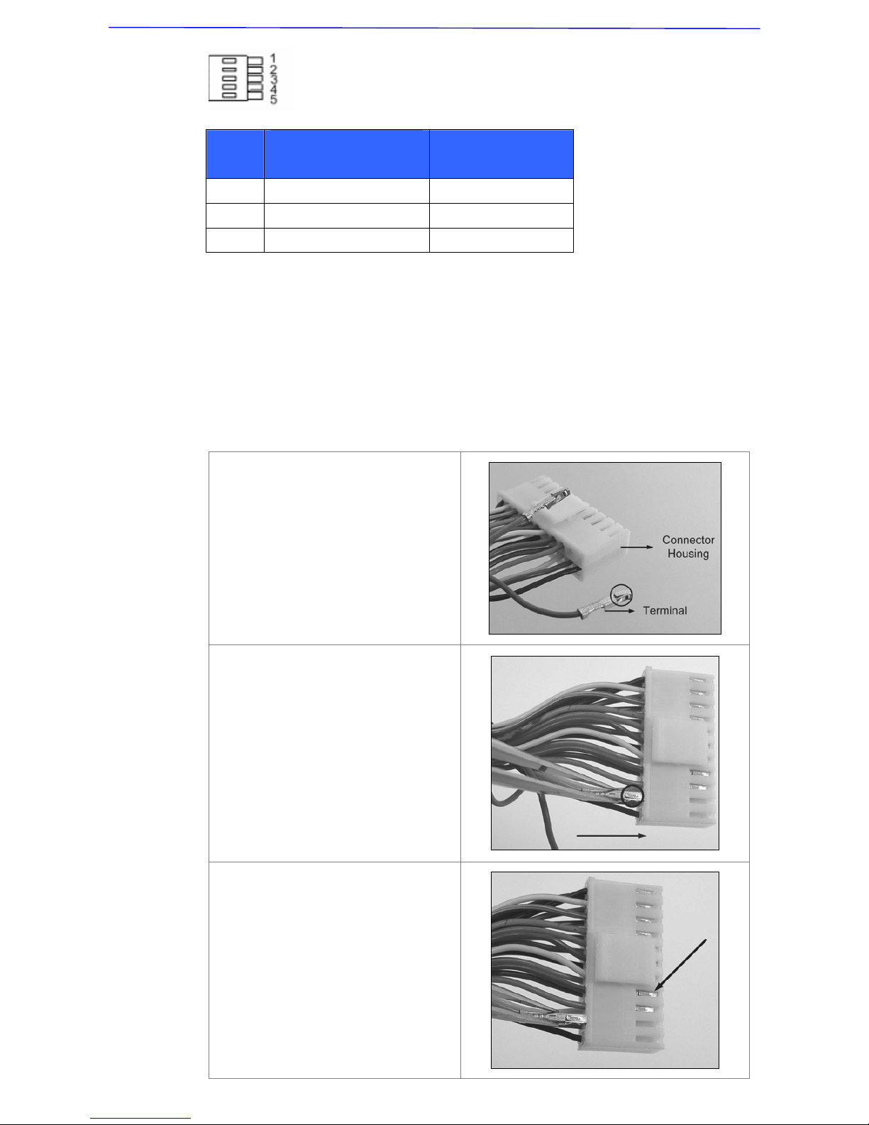
3.3.4 RS-485 Connector Definition
RS-485 is the interface that communicates the dome camera and its control
device. Please connect the control keyboard to the speed dome through the
terminal block. The recommended cables for RS-485 communication are CAT
5 cables; maximum cable length for over 24-gauge wire is 4000 feet (1219
meters). If the total cable length exceeds 4000 feet, using a repeater to
maintain the signals is recommended. Please refer to the figure and table
below for pin defination and wiring.
Page 16
Installation Guide
15
3.3.5 Cable Wiring and Connection
Users may need to do cable wiring when: (1) Connecting self-provided cords
to the connector housing instead of using the equipped data cable or (2)
Connecting alarm input and output devices. The table follows will illustrate the
way to wire cords into the connector housing.
Insert the terminal into the pin
holes on the connector housing,
with the hook outward, as
indicated in the figure.
To unlock the terminal, press the
hook, as indicated in the figure,
with a proper tool and pull it out
gently.
Pin
Corresponding Pins
(22-Pin Connector)
Definition
1 7,10 T+, R+ (D+)
2~4 Reserved
5 8,9 T-, R- (D-)
Page 17
Installation Guide
16
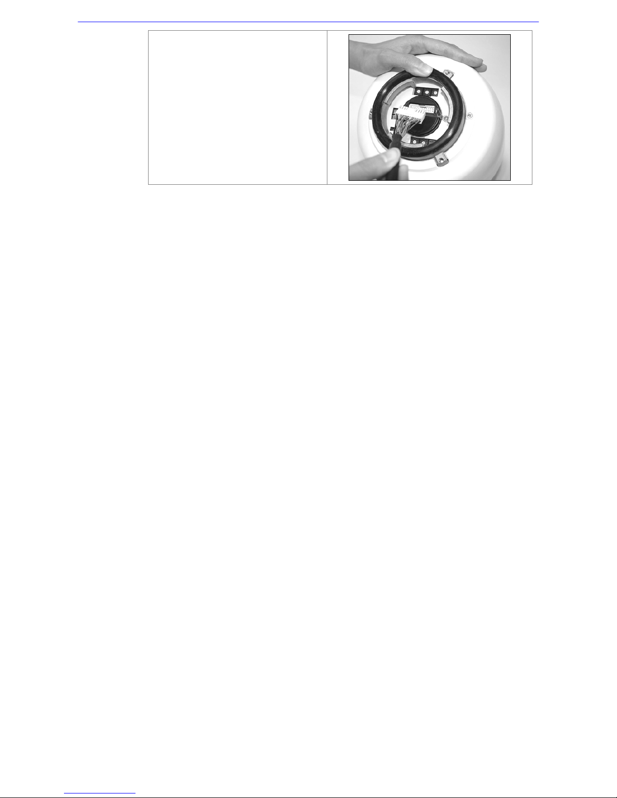
Connect the 22-pin connector to
the dome camera.
Page 18
Installation Guide
17
4. Dome Installation
Basing on user’s installation environments, the dome can be installed on
ceiling, on wall or on pole. In the following section, various dome installation
accessories, installation methods and installation procedures will be
described in detail.
4.1 Dome Dimension
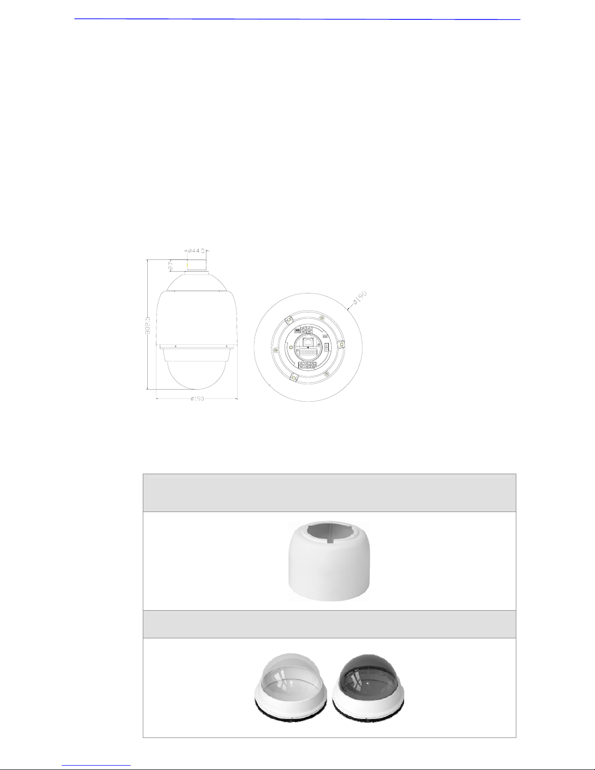
The dome dimension is Ø172 x 302.5mm (6.7x11.9 Inches) and Ø190 x
302.5mm (7.5x11.9 Inches), with sunshield. The diagrams below show
detailed dimension for the dome’s different parts.
4.2 Optional Accessories
Dome Camera Accessories
Sunshield
White Color, Height: 129.5 mm (5.05 inches); Diameter: 190 mm (7.48 inches); 0.15 kg
(0.33 lbs)
Vandal Proof(Transparent)/PMMA (Transparent)/Smoke Cover
Diameter: 137 mm (5.4 inches)
Page 19
Installation Guide
18
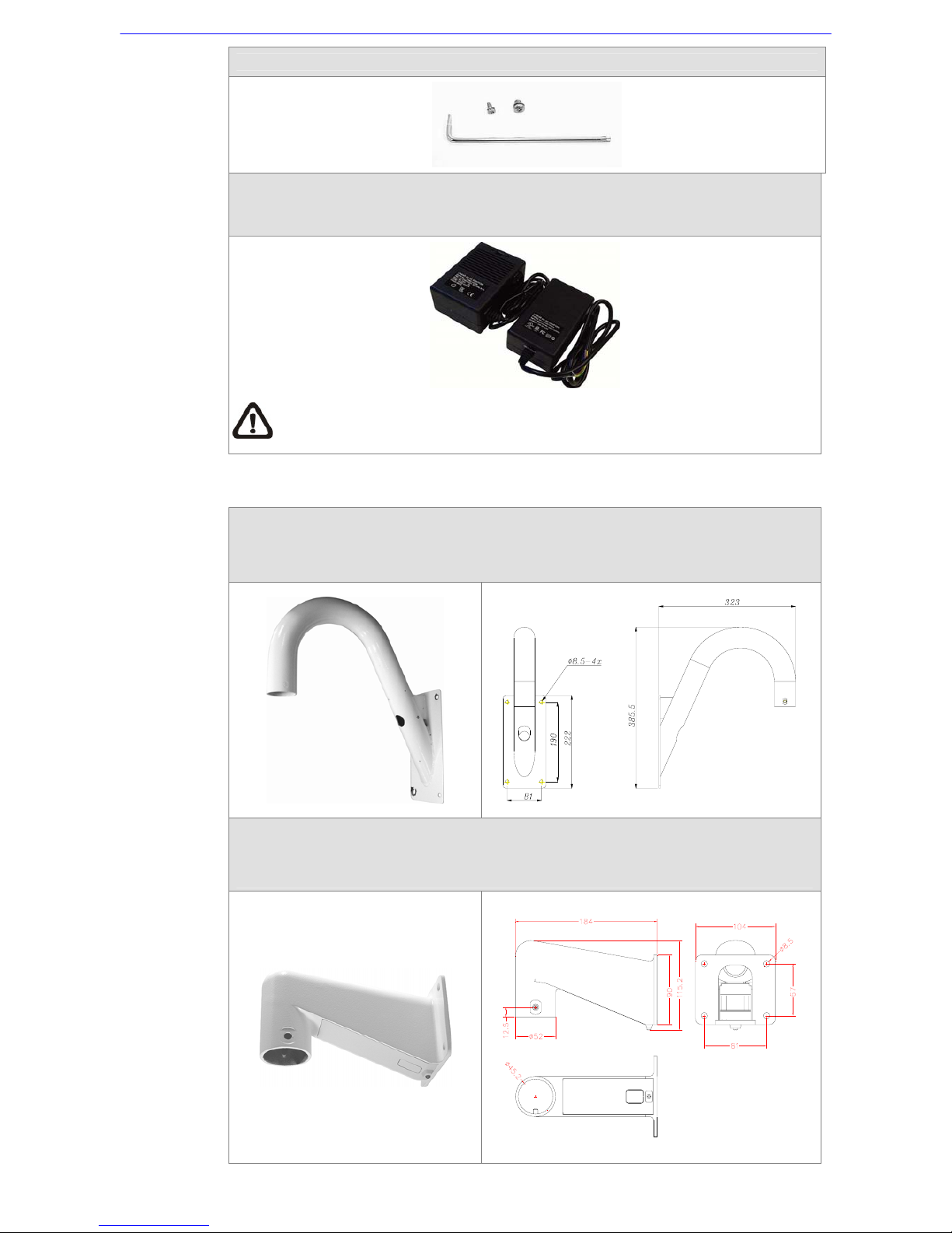
Security Screw Set (equipped with Vandal Proof Cover)
Power Adapter
77H07-A1030 (Input: 100~115VAC/Output: 24VAC 72VA)
77H07-A2030 (Input: 220~230VAC/Output: 24VAC 72VA)
NOTE: When wiring, make sure the G/Y wire (Ground) inserted into the mid-pin of
the terminal block.
Mounting Accessories
Gooseneck Tube
White, Iron, 298×385 mm (11.73×15.56 inches) ; 2.1 kg (4.6 lbs)
Supplied with rubber washer-8×1, pendant tube washer×1, spring washer-8×1 and
waterproof rubber×1, M8*12 screw×1.
Mini Pendent Mount
White; 184×104×115.2 mm (7.24×4.09×4.54 inches)
Supplied with rubber washer-8×1, pendant tube washer×1, spring washer-8×1 and M8*12
screw×1.
Page 20
Installation Guide
19
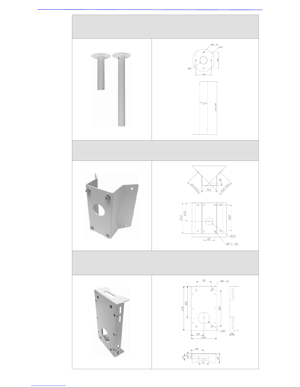
Straight Tube
White, Iron, Height: 250/500 mm (9.8/19.7 inches) ,Diameter: 50 mm (2 inches)
1 kg (2.2 lbs) / 1.8 kg (4 lbs), Supplied with rubber washer-8×1, pendant tube washer×1,
spring washer-8×1 and waterproof rubber×1, M8*12 screw×1.
Corner Standard Mounting Plate
White, 222(L)×204(W)×117(D) mm (8.7×8×4.6 inches); 2 kg (4.4 lbs); Supplied with
washer-8×4, spring washer×4, M8*20 screw×4, M8 nut×4.
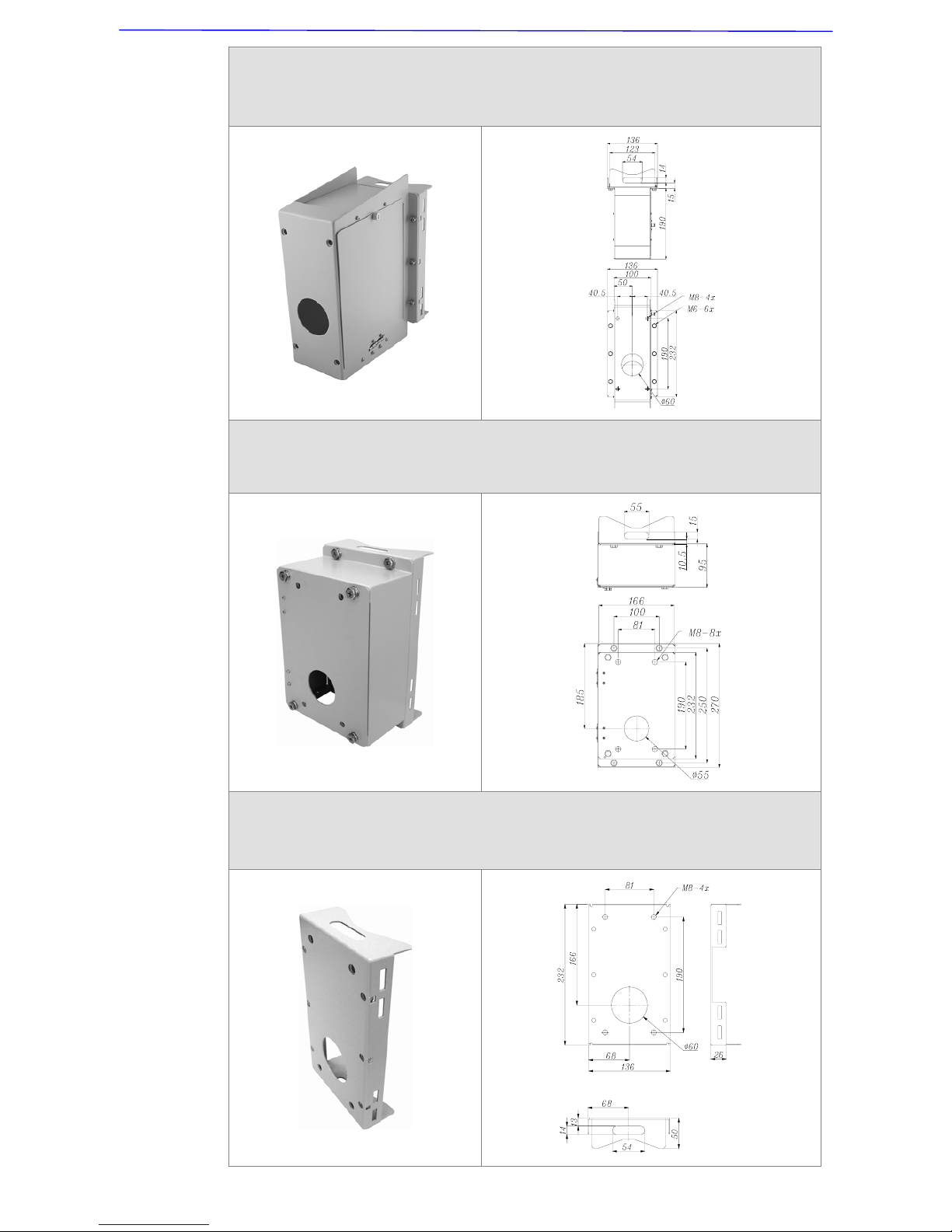
Pole Thin Direct Mounting
White/Ivory; 232(L)×136(W)×60(D) mm (9.1×5.4×2.4 inches); Diameter: 112~140 mm
(4.4~5.5 inches); 0.7 kg (1.6 lbs). Supplied with stainless steel straps×4, M8*16 screw×4,
washer×4.
Page 21
Installation Guide
20
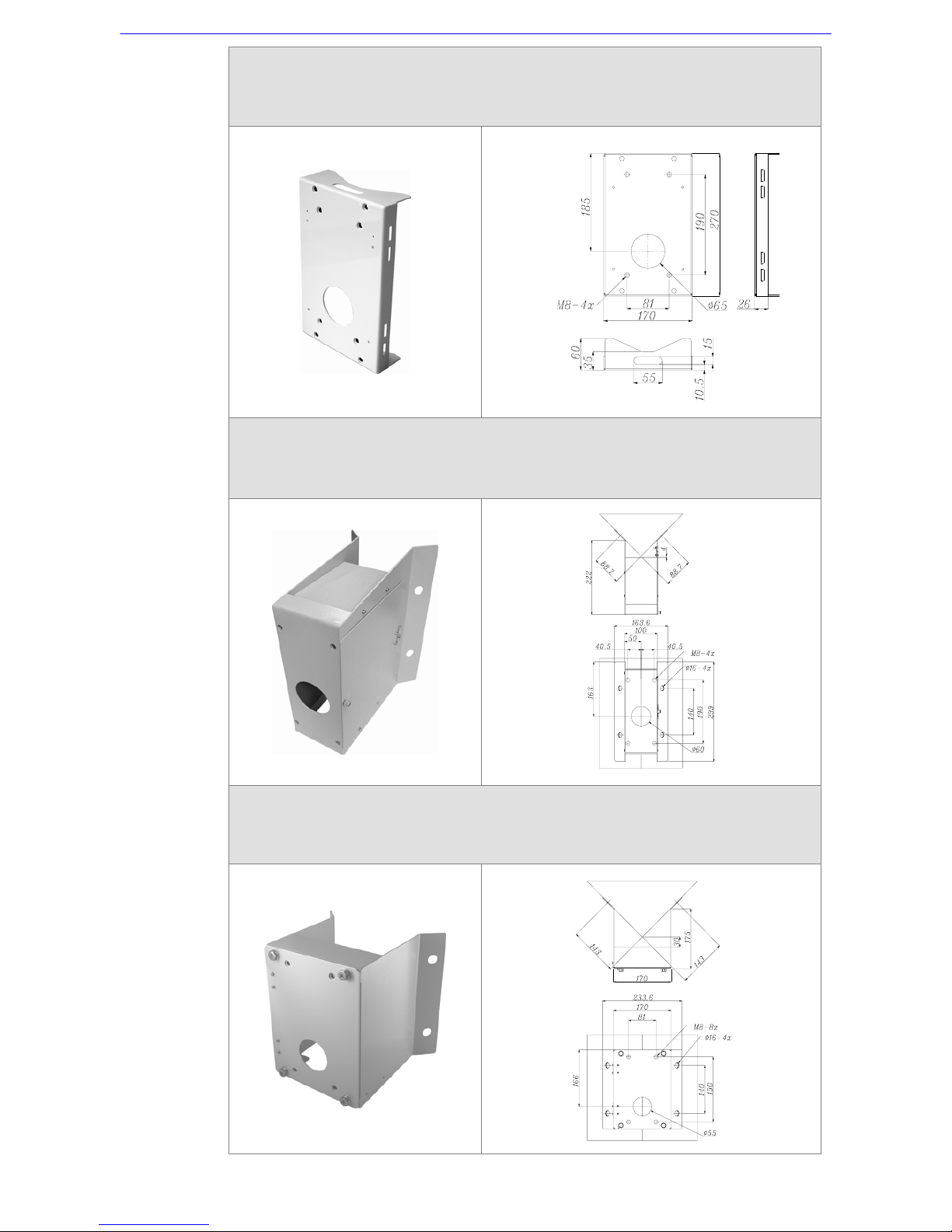
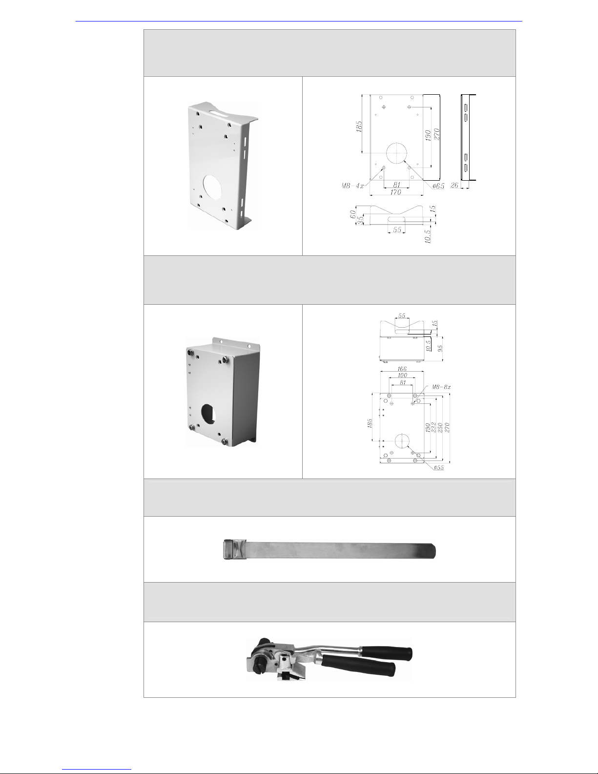
Pole Wide Direct Mounting
White/Ivory; 270(L)×170(W)×60(D) mm (10.6×6.7×2.4 inches); Diameter: 112~130 mm
(4.4~5 inches); 1 kg (2.2 lbs). Supplied with stainless steel straps×4, M8*16 screw×4,
washer×4, spring washer×4
Corner Thin Box
White/Ivory, 300(L)×164(W)×222(D) mm (11.8×6.5×8.7 inches); 3 kg (6.7 lbs); Supplied
with washer×4, M8*16 screw×4 and spring washer×4.
Power Box can be set inside the thin box.
Corner Wide Box
White/Ivory; 232(L)×234(W)×210(D) mm (9.1×9.2×8.3 inches); 2.7 kg (6 lbs); Supplied
with washer×4, M8*16 screw×4 and spring washer×4.
Power Box can be set inside the wide box.
Page 22
Installation Guide
21
Pole Thin Box
White/Ivory; 291(L)×136(W)×245(D) mm (11.5×5.3×9.5 inches); 3.1 kg (6.9 lbs); Supplied
with M8*16 screw×4, washer×4, spring washer×4, stainless steel straps×4.
Power Box can be set inside the thin box.
Pole Wide Box
White/Ivory, 270(L)×166(W)×155(D) mm (10.6×6.5×6.1 inches); 3.2 kg (7.1 lbs); Supplied
with M8*16 screw×4, washer×4, spring washer×4, stainless steel straps×4.
Power Box can be set inside the wide box.
Pole Thin Direct Mount
White/Ivory, 232(L)×136(W)×60(D) mm (9.1×5.4×2.4 inches); Diameter: 112~140 mm
(4.4~5.5 inches); 0.7 kg (1.6 lbs); Supplied with stainless steel straps×4, M8*16 screw×4,
washer×4.
Page 23
Installation Guide
22
Pole Wide Direct Mount
White/Ivory, 270(L)×170(W)×60(D) mm (10.6×6.7×2.4 inches); Diameter: 112~130 mm
(4.4~5 inches); 1 kg (2.2 lbs); Supplied with stainless steel straps×4, M8*16 screw×4,
washer×4, spring washer×4
Wall Box Mounting
White/Ivory, 270(L)×166(W)×95(D) (10.6×6.5×3.7 inches); 2.2 kg (4.84 lbs); Supplied with
M8*16 screw×4, washer×4, spring washer×4
Power Box can be set inside the wall box.
Stainless Steel Straps
For fixing Pole Direct Mounting/ Pole Box on the pole.
Length: 700 mm (27.5 inches); Width: 0.63”; 0.02 kg (0.04 lbs)
Stainless Strap Cutter
For tension, cut and crimp stainless steel straps. 1.4 kg (3.1 lbs)
Suitable for straps width: 1/2”, 5/8”, 3/4”
Page 24
Installation Guide
23
Other Application Accessories
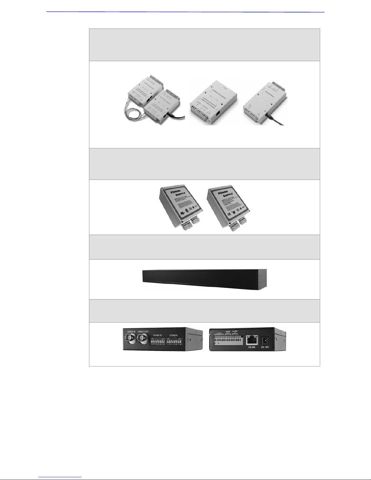
Repeater/Converter
D77R1: RS-485/RS-232 Converter
D77R2: RS-232 between RS-485/RS-442
D77R3: Bi-phase to RS-485/RS-422
D77R1 D77R2 D77R3
Power Box
White, 186.5×147 mm (7.3×5.8 inches); 2.6 kg (5.8 lbs)
P1030 (Input: 110~115VAC/Output: 24VAC 72VA)
P2030 (Input: 220~230VAC/Output: 24VAC 72VA)
Signal Distribution Unit
Relay control codes to speed dome cameras.
Dimension: 432×44×90 mm (17×17.32×35.43 inches)
Coaxial Box
Transmit video and RS-485 control signals via one BNC line.
Dimension: 100×90×28 mm (3.93×3.54×1.1 inches)
Front View Rear View
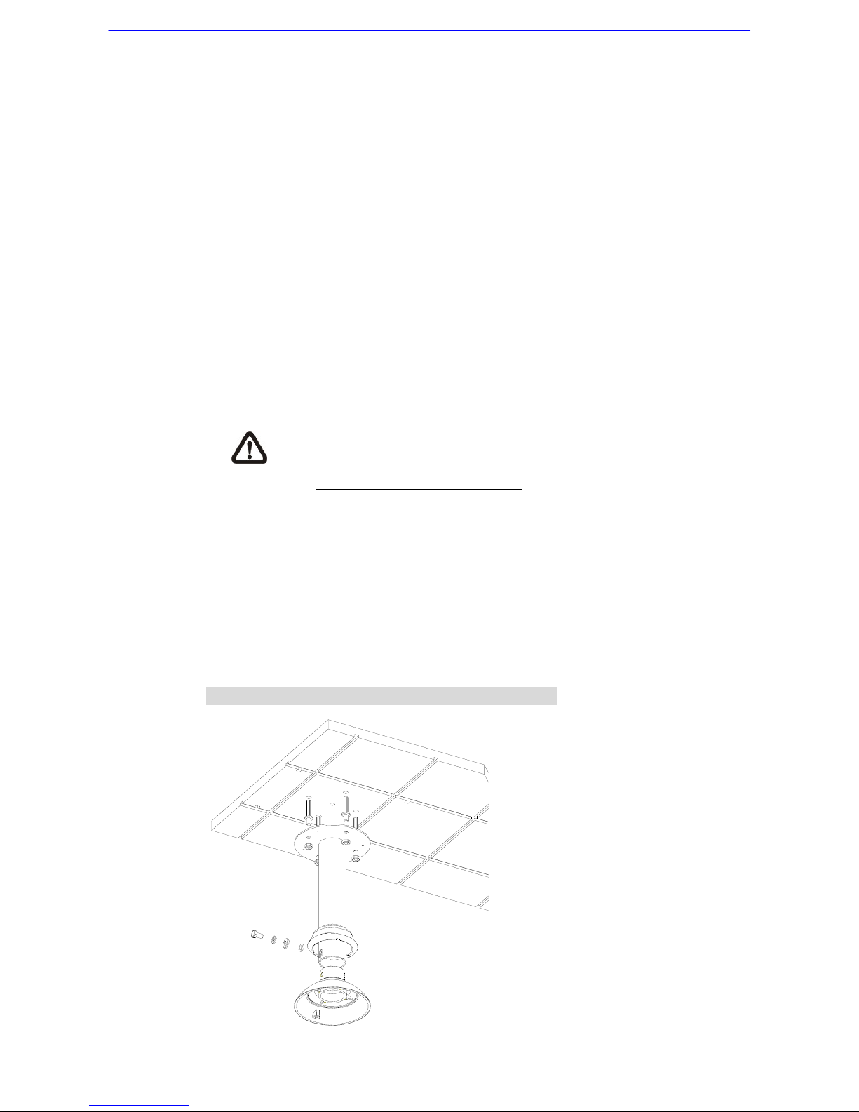
4.3 Ceiling Mounting with Straight Tube
The straight tube is available in different length: 25 cm and 30 cm. The
supplied item is in the dome camera package.
Items Needed:
• Dome Camera
Page 25
Installation Guide
24
• Straight Tube and other equipped items (optional accessory)
• Waterproof Rubber (supplied)
• Screws and Screw Anchors for fixing the straight tube onto the ceiling (not
supplied)
Tools Needed:
• Tool for drilling
• Tool for screwing
Follow the steps to mount the dome with the straight tube.
1) Ensure that the ceiling can support the weight of the dome camera and
straight tube.
2) Make a cable entry hole on the ceiling.
3) Fix the Straight Tube to the ceiling with proper screws and screw anchors
(not supplied).
Please replace the rubber equipped with the gooseneck/straight
tube, with the waterproof rubber packed in the standard package
(See 2. Standard Package Content).
4) Thread the cables through the straight tube and the top holder.
5) Fix the top holder to the straight tube with the supplied screws and
washers. Then adjust the waterproof rubber to the junction of straight tube
and top holder.
6) Connect the cables to the dome camera. Then attach the dome to the top
holder and fix them with the supplied screw.
Ceiling Mount: Straight Tube + Waterproof Rubber
Page 26
Installation Guide
25
4.4 Wall Mount
4.4.1 Wall Mounting with Gooseneck Tube
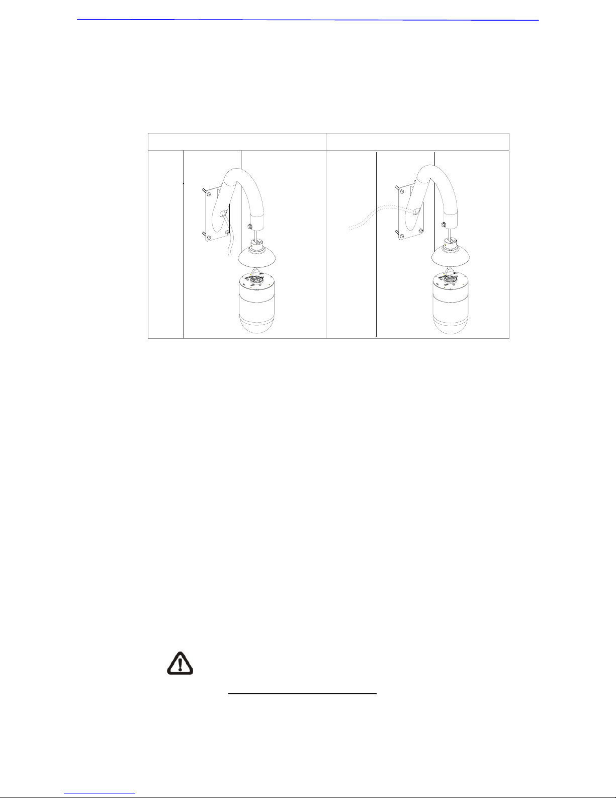
The following figures show how cables run through the tube in different ways.
Cables exposed Cables recessed
Items Needed:
• Dome Camera
• Gooseneck Tube and other equipped items (optional accessory)
• Waterproof Rubber (standard accessory)
• Screws and Screw Anchors for fixing the gooseneck tube onto the ceiling
(not supplied)
Tools Needed:
• Tool for drilling
• Tool for screwing
Follow the steps to mount the dome with the gooseneck tube.
1) Make a cable entry hole on the wall to recess the cables. Otherwise,
cables can be threaded through the cable entry hole on the tube.
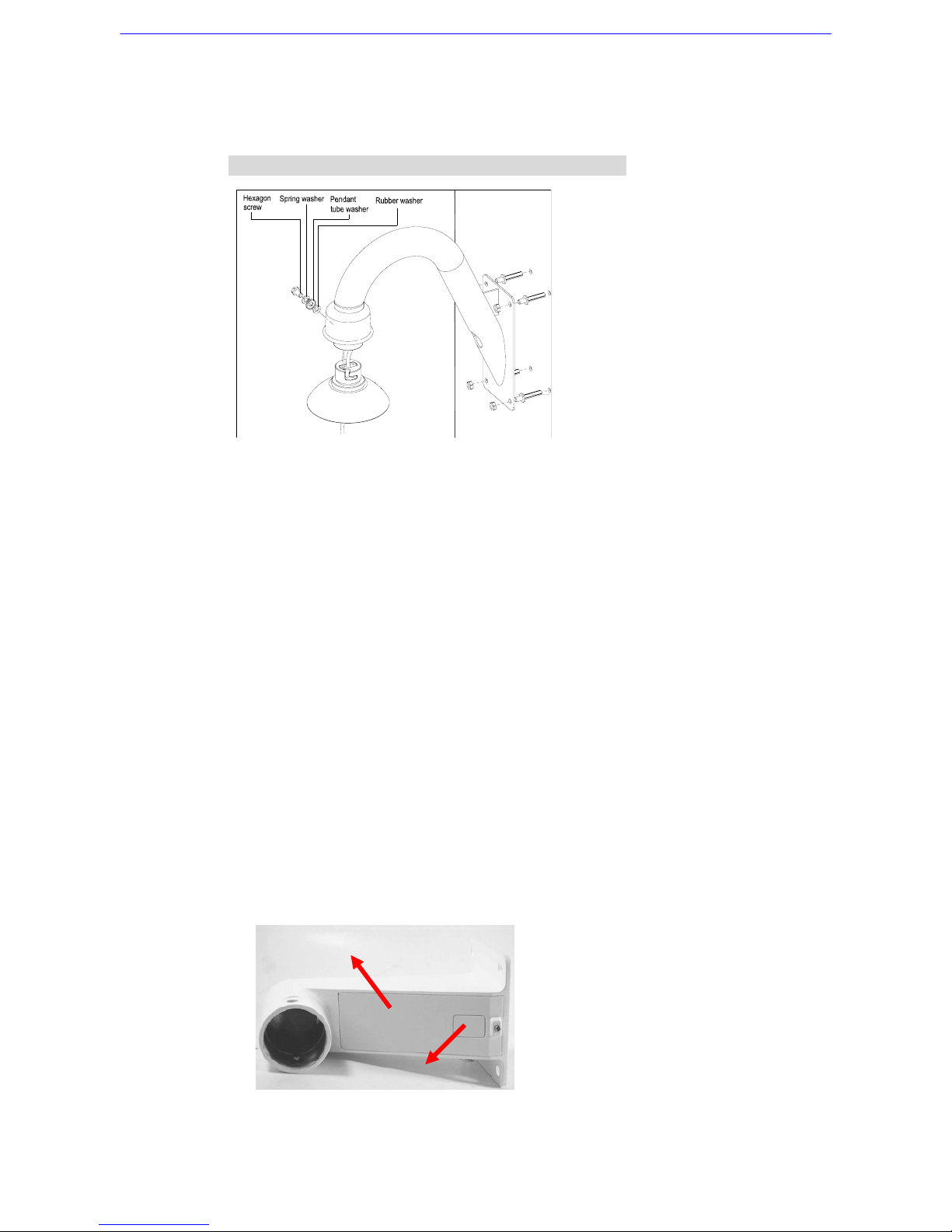
2) Fix the Gooseneck Tube on the wall with proper screws and screw
anchors (not supplied).
Please replace the rubber equipped with the gooseneck/straight
tube, with the waterproof rubber packed in the standard package
(See 2. Standard Package Content).
3) Thread the cables through the gooseneck tube and the top holder.
4) Fix the top holder to the gooseneck tube with the supplied screws and
washers. Then adjust the waterproof rubber to the junction of straight tube
Page 27
Installation Guide
26
and top holder.
5) Connect the cables to the dome camera. Then attach the dome to the top
holder and fix them with the supplied screw.
Wall Mount: Gooseneck Tube + Waterproof Rubber
4.4.2 Mini Pendant Mount
Items Needed:
• Dome Camera
• Mini Pendant Mount and other equipped items (optional accessory)
• Screws and Screw Anchors for fixing the Mini Pendant Mount (not
supplied)
Tools Needed:
• Tool for drilling
• Tool for screwing
Follow the steps to mount the dome with the Mini Pendant Mount.
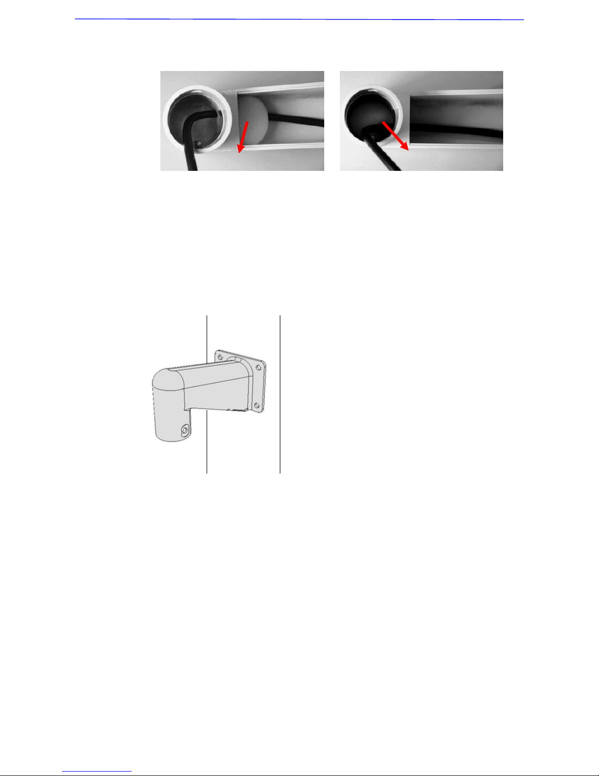
1) Make a cable entry hole on the wall to recess the cables. Otherwise, users
could push up the cable entry board on the Mini Pendant Mount’s
mounting plate to place the cables, as shown in the photo below.
2) To avoid insects entering the pendant mount, you could block the cable
entry hole with the supplied sponge in two ways. See the illustrations
Cable Entry Board
Mounting Plate
Page 28
Installation Guide
27
below.
3) Thread the cables through the Mini Pendant Mount and fix the pendant
mount on the wall with proper screws and screw anchors (not supplied).
4) Thread the cables through the top holder and fix it to the Mini Pendant
Mount with the supplied screws and washers.
5) Connect the cables to the dome camera. Then attach the dome to the top
holder and fix them with the supplied screw.
4.4.3 Wall Box Mounting
Items Needed:
• Dome Camera
• Gooseneck Tube and other equipped items (optional accessory)
• Wall Box (optional accessory)
• Waterproof Rubber (standard accessory)
• Screws and Screw Anchors for fixing the wall box onto the ceiling (not
supplied)
Tools Needed:
• Tool for drilling
• Tool for screwing
Follow the steps to mount the dome with the gooseneck tube and wall box.
Sponge
Sponge
Page 29
Installation Guide
28
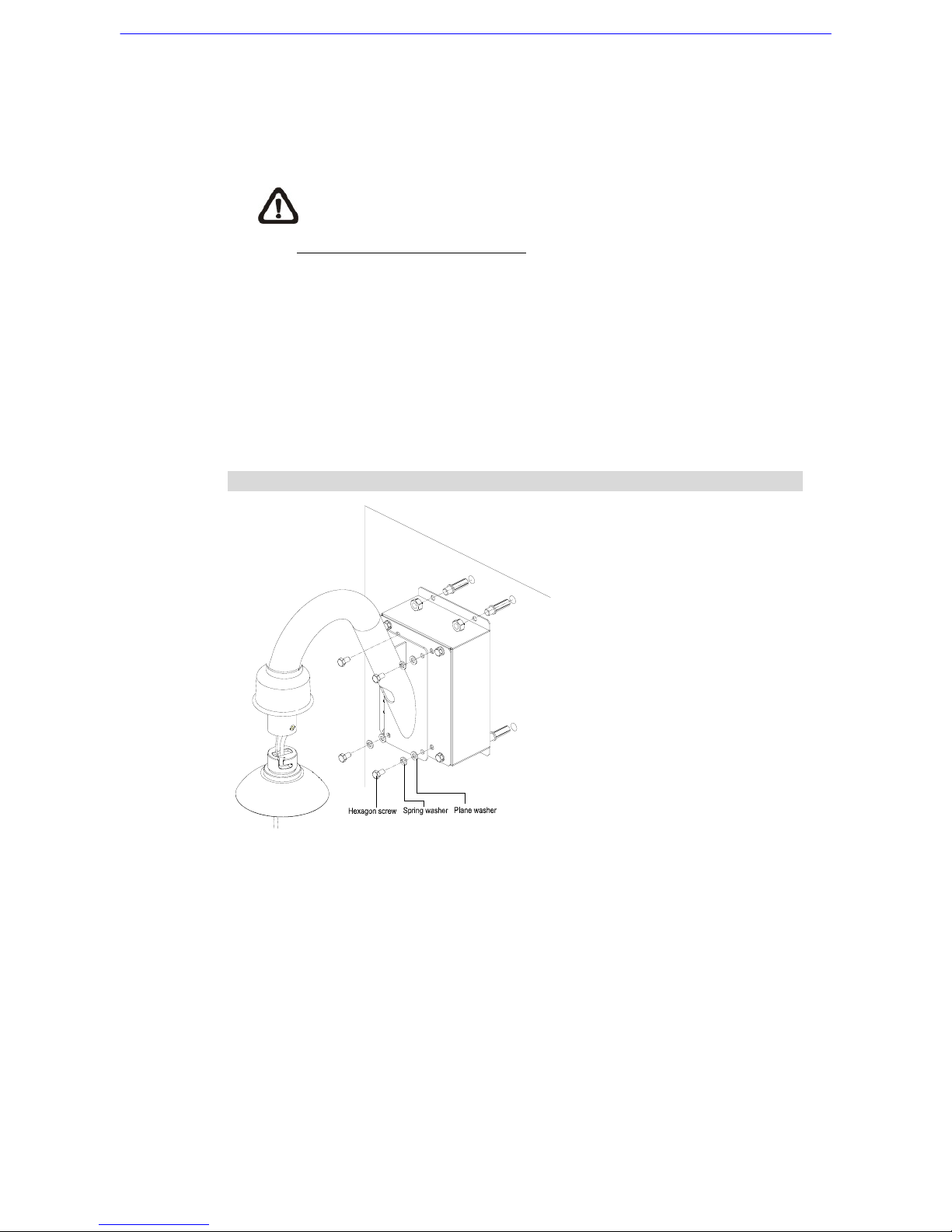
1) Fix the Wall Box on wall with proper screws and screw anchors (not
supplied).
2) Fasten the gooseneck tube on the wall box with the supplied screws and
washers.
Please replace the rubber equipped with the gooseneck/straight
tube, with the waterproof rubber packed in the standard package
(See 2. Standard Package Content).
3) Thread the cables through the gooseneck tube and the top holder.
4) Fix the top holder to the gooseneck tube with the supplied screws and
washers. Then adjust the waterproof rubber to the junction of straight tube
and top holder.
5) Connect the cables to the dome camera. Then attach the dome to the top
holder and fix them with the supplied screw.
Wall Box Mount: Wall Box Mount + Gooseneck Tube + Waterproof Rubber
4.5 Corner Mount
4.5.1 Corner Standard Mounting Plate
With the corner mounting plate and gooseneck, the dome can be mounted on
corner wall.
Items Needed:
• Dome Camera
• Gooseneck Tube and other equipped items (optional accessory)
• Corner Standard Mounting Plate (optional accessory)
Page 30
Installation Guide
29
• Waterproof Rubber (standard accessory)
• Screws and Screw Anchors for fixing the Corner Standard Mounting Plate
(not supplied)
Tools Needed:
• Tool for drilling
• Tool for screwing
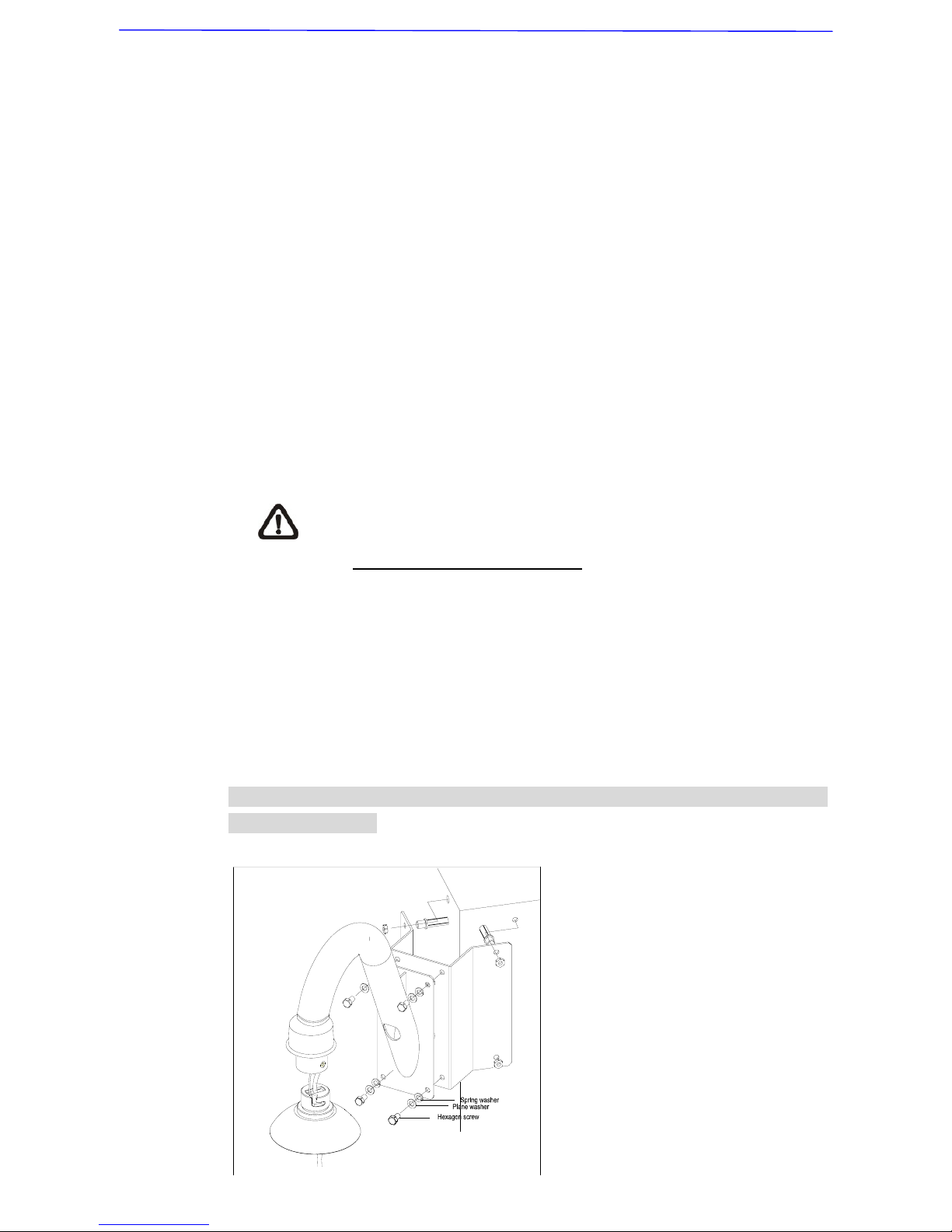
Follow the steps below to mount the dome camera with the corner standard
mounting plate and gooseneck tube.
1) Make a cable entry hole on the wall to recess the cables. Otherwise,
cables can be threaded through the cable entry hole on the tube.
2) Fix the Corner Standard Mounting Plate on corner wall with proper screws
and screw anchors (not supplied).
3) Attach the gooseneck tube to the fixed mounting plate with the supplied
screws and washers.
Please replace the rubber equipped with the gooseneck/straight
tube, with the waterproof rubber packed in the standard package
(See 2. Standard Package Content).
4) Thread the cables through the gooseneck tube and the top holder.
5) Fix the top holder to the gooseneck tube with the supplied screws and
washers. Then adjust the waterproof rubber to the junction of straight tube
and top holder.
6) Connect the cables to the dome camera. Then attach the dome to the top
holder and fix them with the supplied screw.
Corner Wall Mounting: Corner Standard Mounting Plate + Gooseneck Tube +
Waterproof Rubber
Page 31

Installation Guide
30
4.5.2 Corner Thin/Wide Box Mounting
The corner thin/wide box is designed to be installed with a gooseneck tube.
Items Needed:
• Dome Camera
• Gooseneck Tube and other equipped items (optional accessory)
• Corner Thin/Wide Box (optional accessory)
• Waterproof Rubber (standard accessory)
• Screws and Screw Anchors for fixing the Corner Thin/Wide Box (not
supplied)
Tools Needed:
• Tool for drilling
• Tool for screwing
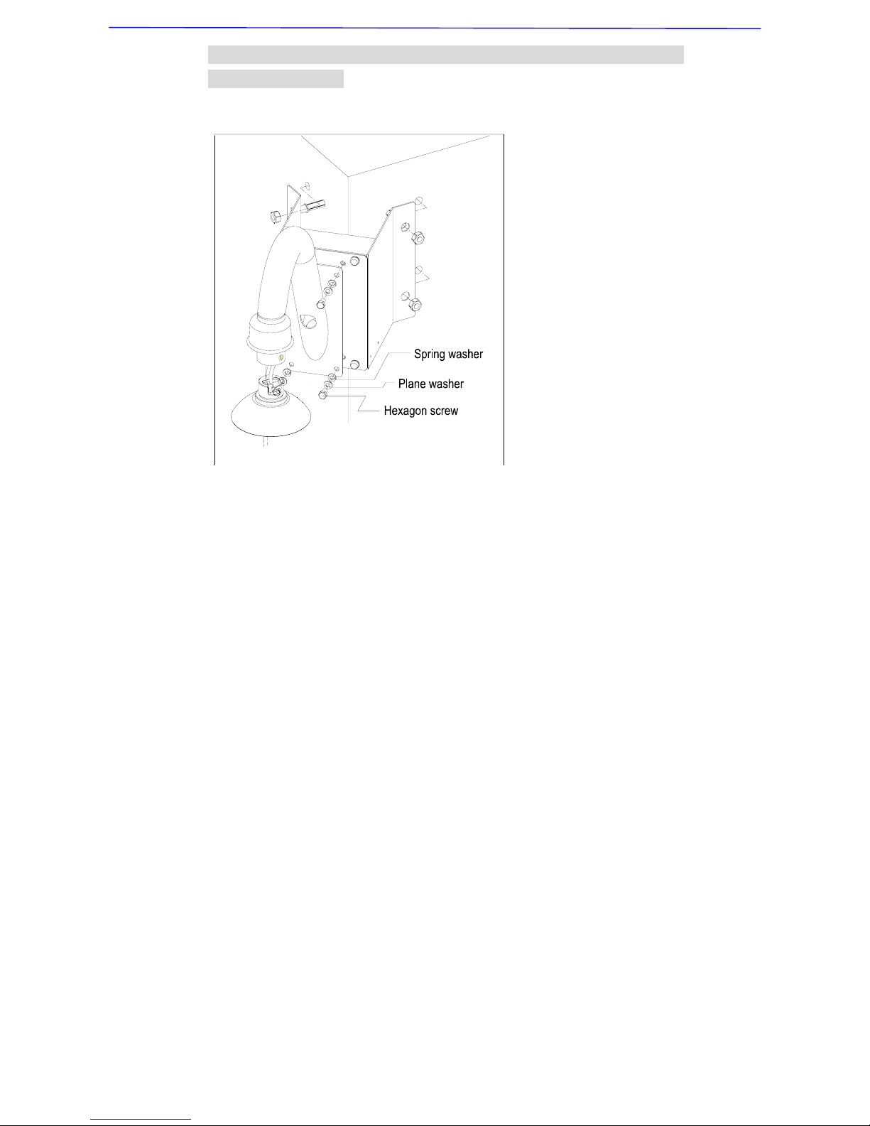
Follow the steps to mount the dome with the corner box and gooseneck tube.
1) Make a cable entry hole on the wall to recess the cables. Otherwise,
cables can be threaded through the cable entry hole on the tube.
2) Fix the Corner Thin/Wide Box on corner wall with proper screws and
screw anchors (not supplied).
3) Attach the gooseneck tube to the fixed corner box with the supplied
screws and washers.
Please replace the rubber equipped with the gooseneck/straight
tube, with the waterproof rubber packed in the standard package
(See 2. Standard Package Content
).
4) Thread the cables through the gooseneck tube and the top holder.
5) Fix the top holder to the gooseneck tube with the supplied screws and
washers. Then adjust the waterproof rubber to the junction of straight tube
and top holder.
6) Connect the cables to the dome camera. Then attach the dome to the top
holder and fix them with the supplied screw.
Page 32
Installation Guide
31
Corner Box Mounting: Corner Thin/Wide Box + Gooseneck Tube +
Waterproof Rubber
4.6 Pole Mount
4.6.1 Pole Thin/Wide Direct Mounting
The dome can be installed on a pole with a thin/wide direct mounting
accessory and a gooseneck.
Items Needed:
• Dome Camera
• Gooseneck Tube and other equipped items (optional accessory)
• Waterproof Rubber (standard accessory)
• Pole Thin/Wide Direct Mounting (optional accessory)
• Stainless Steel Straps (optional accessory)
Tools Needed:
• Stainless Strap Cutter
• Tool for screwing
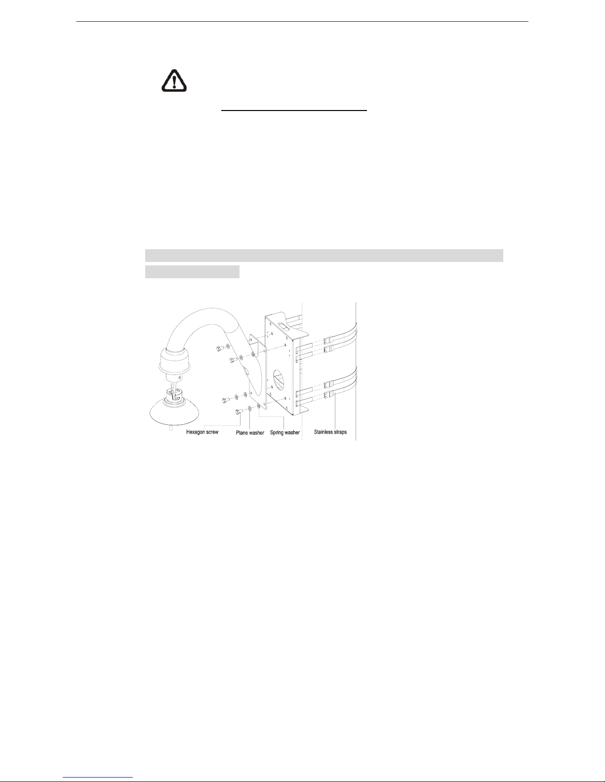
Follow the steps below to mount the dome camera with the pole direct
mounting and gooseneck.
1) Fasten the Pole Thin/Wide Direct Mounting on a pole with equipped
stainless straps.
2) Fix the gooseneck tube on the pole direct mounting with the supplied
Page 33
Installation Guide
32
screws and washers.
Please replace the rubber equipped with the gooseneck/straight
tube, with the waterproof rubber packed in the standard package
(See 2. Standard Package Content).
3) Thread the cables through the gooseneck tube and the top holder.
4) Fix the top holder to the gooseneck tube with the supplied screws and
washers. Then adjust the waterproof rubber to the junction of straight tube
and top holder.
5) Connect the cables to the dome camera. Then attach the dome to the top
holder and fix them with the supplied screw.
Pole Direct Mount: Pole Thin/Wide Direct Mounting +Gooseneck Tube +
Waterproof Rubber
4.6.2 Pole Thin/Wide Box Mounting
Items Needed:
• Dome Camera
• Gooseneck Tube and other equipped items (optional accessory)
• Waterproof Rubber (standard accessory)
• Pole Thin/Wide Box(optional accessory)
• Stainless Steel Straps (optional accessory)
Tools Needed:
• Stainless Strap Cutter
• Tool for screwing
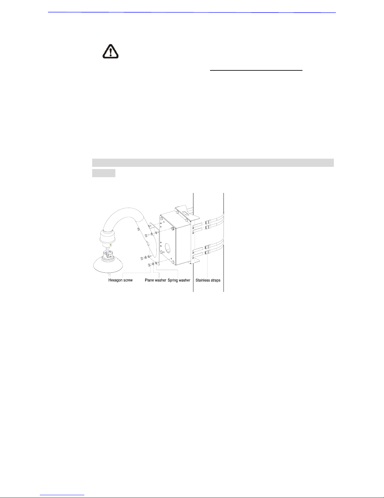
Follow the steps to mount the dome camera with the pole box and gooseneck
tube.
1) Fasten the Pole Thin/Wide Box on a pole with equipped stainless straps.
2) Fix the gooseneck tube on the pole box with the supplied screws and
Page 34
Installation Guide
33
washers.
If use an outdoor dome, please replace the rubber equipped with
the gooseneck/straight tube, with the waterproof rubber packed in
the standard package (See 2. Standard Package Content).
3) Thread the cables through the gooseneck tube and the top holder.
4) Fix the top holder to the gooseneck tube with the supplied screws and
washers. Then adjust the waterproof rubber to the junction of straight tube
and top holder.
5) Connect the cables to the dome camera. Then attach the dome to the top
holder and fix them with the supplied screw.
Pole Box Mount: Pole Thin/Wide Box + Gooseneck Tube + Waterproof
Rubber
Page 35
Installation Guide
34
5. System Expansion
5.1 Connecting with Power Box
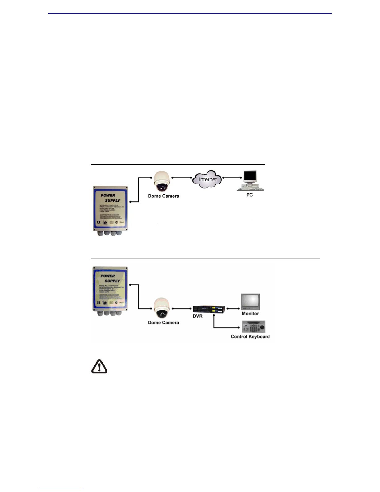
A power box contains a 24V AC adapter, two terminal blocks (for
communication and power) and one alarm board. With an IP66 case, the
Power Box is ideal for outdoor installation environment. Two models are
available: 100~115V AC power input (P1030) and 220~230V AC (P2030).
Additionally, users can either connect one dome camera to one power box
and to Internet or to other control devices (DVR, Control Keyboard and
monitors), as shown in the diagrams below. For more detailed information,
please refer to the power box user’s manual.
Connecting the Dome to the Power Box and Internet
Connecting the Dome to the Power Box and Various Control Devices
NOTE: One power box can only be connected to one outdoor dome
camera subject to voltage restriction. In addition, up to two indoor
dome cameras are allowed to be used with one power box.
Page 36
Installation Guide
35
5.2 Data Formats Transforming
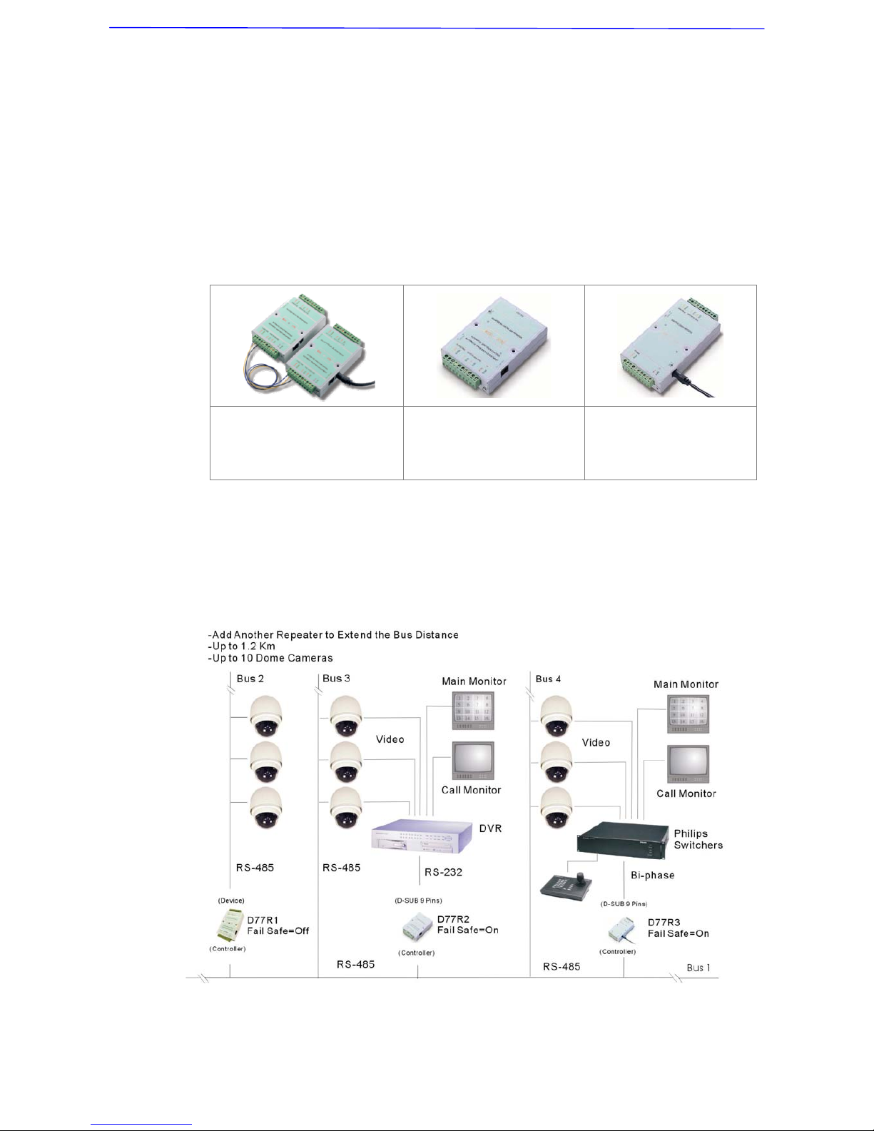
To integrate other surveillance devices with the high speed dome cameras or
to extend the distance of communications, users could employ three kinds of
repeater/converter, as shown below. With the advanced circuit design, these
repeaters/converters offer 1KVrms isolation voltage and surge protection
capability. The exiting network can be protected by the repeaters/converters.
Up to 10 devices are allowed to connect to one repeater/converter. For
detailed information, please refer to the repeater/converter user’s manual.
D77R1
RS-485/RS-422 Repeater
D77R2
RS-232 between
RS-485/RS-422
D77R3
Bi-Phase to
RS-485/RS-422
D77R1: Extend the distance of RS-485 or RS-422 communications
D77R2: Either Bridge RS-232 equipments to a RS-485 or RS-422 network or
bridge RS-485/RS-422 equipments to a RS-232 network
D77R3: Bridge Bi-Phase equipments to a RS-485 or RS-422 network
Page 37
Installation Guide
36
5.3 Signal Distribution
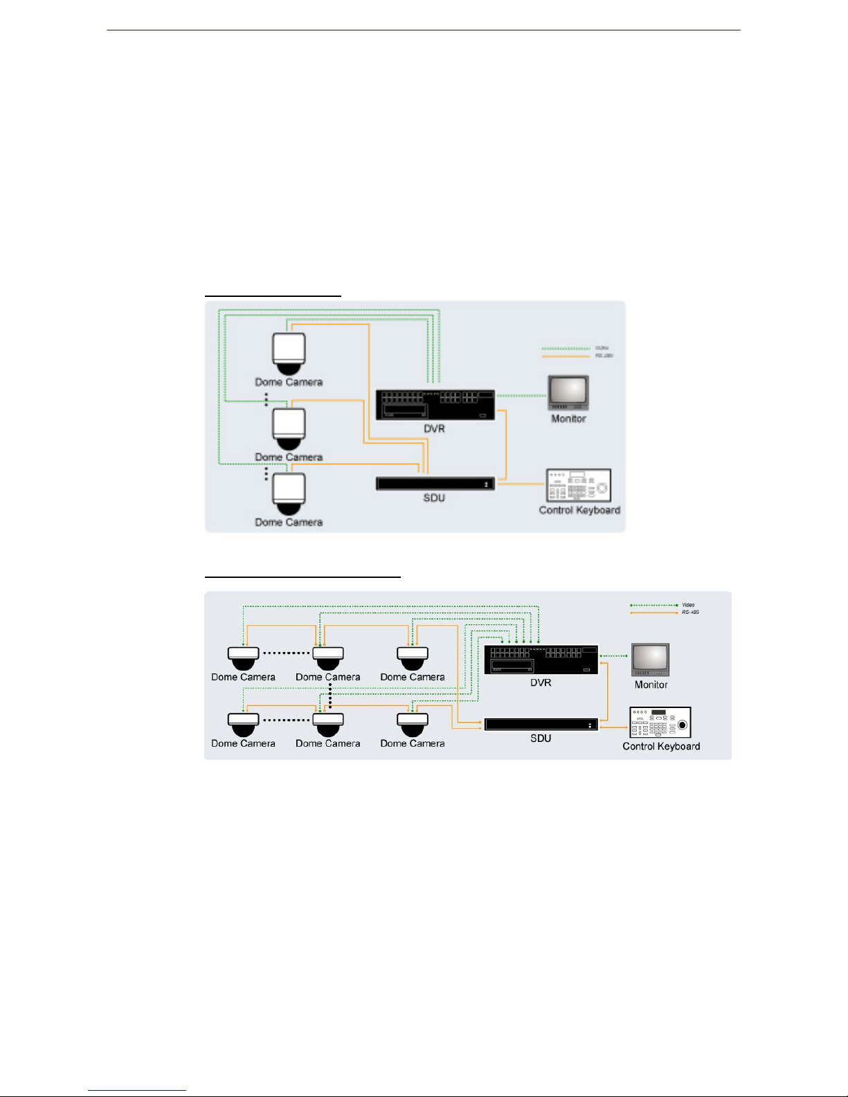
The RS-485 Signal Distribution Unit (SDU) is designed to relay control codes
to speed dome cameras. It is capable of communicating with cameras up to
1.0 kilometers away. Additionally, the SDU can be installed in either “star” or
“daisy chain” configuration with up to 160 cameras (see the diagrams below).
Its versatile installation configuration makes an easy integration into
expanding surveillance systems. For more information, please refer to the
SDU user’s manual.
Star Configuration
Daisy Chain Configuration
Page 38
Installation Guide
37
5.4 Coaxial Telemetry
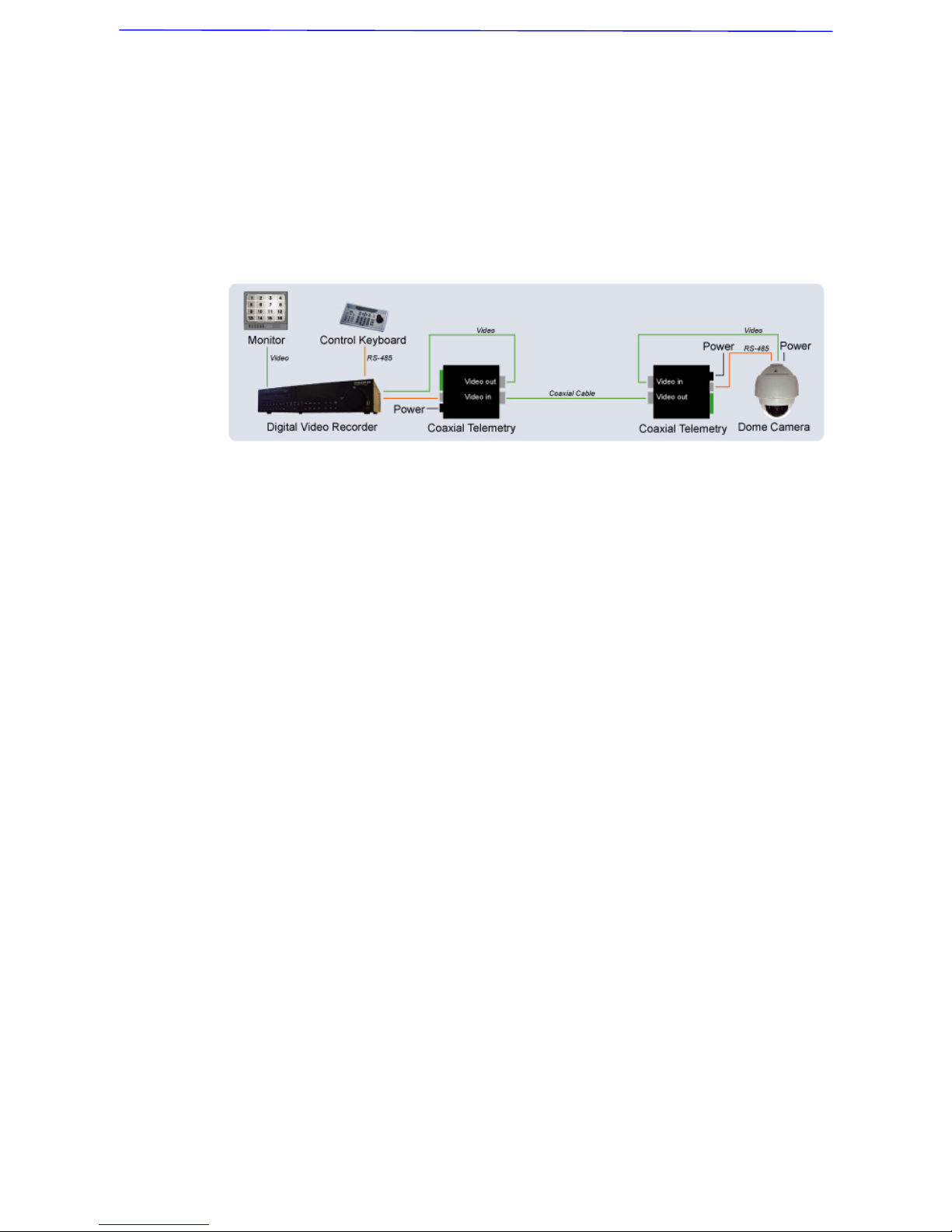
The Coaxial Telemetry is a low-cost solution to long distance connection
between dome cameras and controlling devices (e.g. DVR and keyboard). It
simplifies the work of wiring by transmitting video and RS-485 control signals
via one BNC line, so that to bring users economical benefits. The following is
the coaxial telemetry application diagram. For more information, please refer
to the coaxial telemetry’s quick installation guide.
Page 39
Installation Guide
38
6. System Integration
The dome camera is allowed to be integrated into other suppliers'
surveillance systems with large set of built-in protocols. Refer to the following
sections for more information.
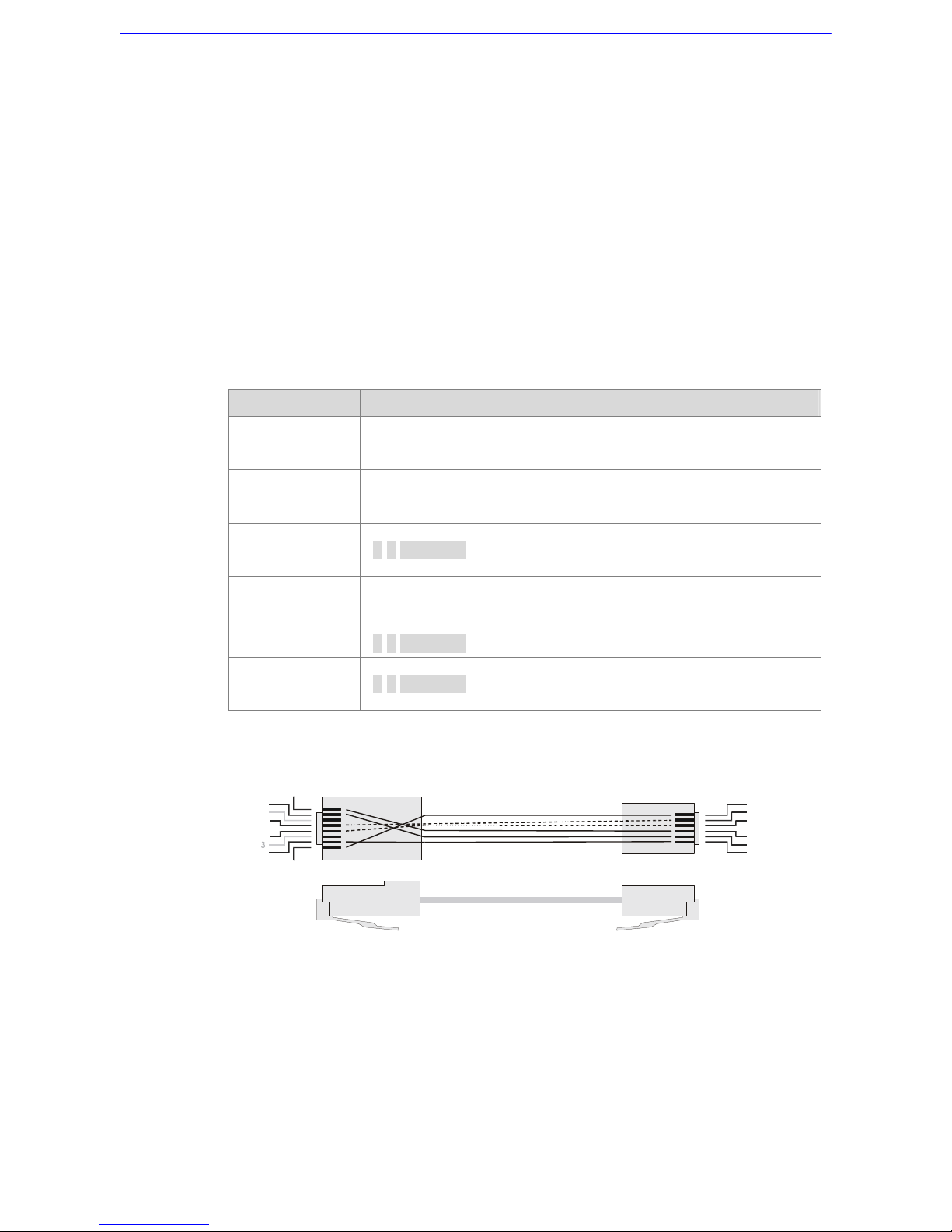
6.1 Using Pelco Keyboard
The speed dome camera can be controlled through a Pelco keyboard which
built in with D protocol and P protocol. Please follow the instruction to
manipulate our speed dome by a keyboard with D and P protocols.
Function Instruction
Set Preset
Number key + press and hold <Preset > button for three
seonds.
Go Preset
Number key + <Preset> to command a dome camera to go to
a specific preset position.
Display or hide
an OSD menu
7 7 <Preset>
Move the cursor
in OSD menu
Move the cursor up/down/right/left by pushing the joystick
up/down/right/left respectively
<ENTER>
7 7 <Preset>
Reset the dome
camera
7 8 <Preset>
Cable Definition (P Protocol Keyboard to PTZ Camera)
For P Protocol Keyboard
For SpeedDome
1
2
4
5
6
7
8
Tx -
Tx +
+12V
GND
Rx-
Rx+
1
2
3
4
5
6
Tx-
Tx +
+12V
GND
Rx-
Rx+
Page 40
Installation Guide
39
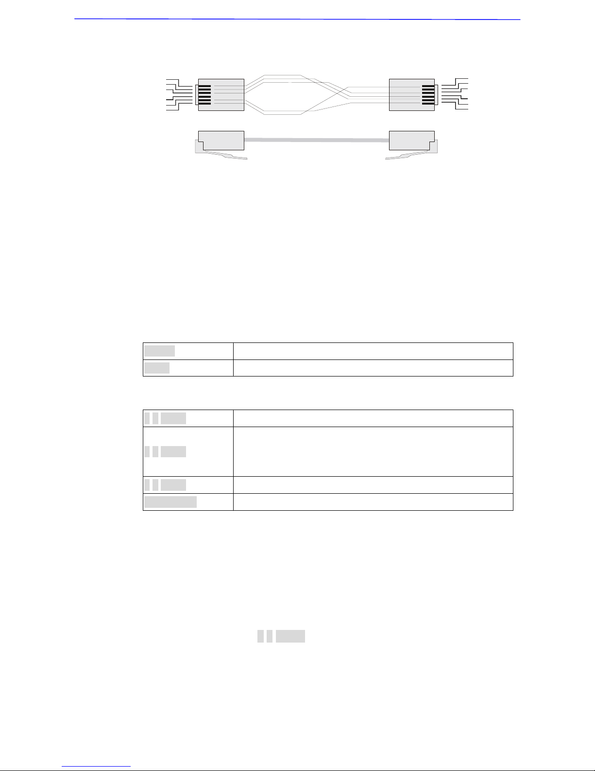
Cable Definition (D Protocol Keyboard to PTZ Camera)
For SpeedDomeFor D Protocol Keyboard
Tx -
Tx +
GND
Rx-
Rx+
1
2
3
4
5
6
Tx Tx +
GND
Rx Rx+
1
2
3
4
5
6
GND
6.2 Using Philips Allegiant Keyboard
The dome cameras can be integrated into Philips Allegiant systems through
D77R3 repeaters. Please follow the instructions to control dome cameras
through Philips Allegiant systems.
Symbol Definition
<shot> Command dome cameras to go to specific preset position.
<set> Set preset position.
Special Function
7 6 <set> Exit OSD menu directly.
7 7 <set>
1. Display or hide OSD menu.
2. Virtual key to send an ENTER command when OSD is
displayed.
7 8 <set> Reset doma camera.
<Iris Open> Send an ENTER command when OSD is displayed.
Control Dome Camera Using Allegiant Keyboard
• User can move the cursor left/right/up/down through pushing joystick
left /right/up/down.
• Some differences for ENTER command.
User cannot send ENTER command directly. User can send a ENTER
command through “ 7 7 <Set> “.
Page 41
Installation Guide
40
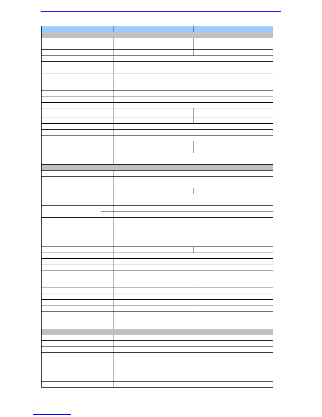
Appendix A: Technical Specification
Items R Model K Model
CAMERA
CCD Sensor 1/4" CCD 1/4" CCD
Progressive Scan - Yes
Optical Zoom 22× 23x
Digital Zoom 1×~ 12× variable
NTSC 380k
Effective Pixels
PAL 440k
NTSC 480 TVL
Horizontal Resolution
PAL 480 TVL
Scanning System NTSC / PAL
Synchronization Internal / Line Lock
Video Output 1.0 Vp-p / 75 Ω, BNC
S/N Ratio > 50 dB (AGC Off)
Minimum Illumination 1 lux
0.1 lux;
0.01 lux(B/W)
Focal Length 4~88 mm 3.6~82.8 mm
Focus Mode Auto / Manual
White Balance Auto / Manual
Iris Control Auto / Manual
NTSC 1/60~1/30k sec. 1/2~1/30k sec.
Electronic Shutter
PAL 1/50~1/30k sec 1/1.5~1/30k sec
AGC control Auto / Manual
Back Light Compensation On / Off
OPERATION
Built-in Protocol DynaColor, Pelco D&P, VCL, Philips, AD-422, JVC, Kalatel, etc.
Multi-Language OSD English, French, German, Italian, Japanese, Polish, Portuguese, Russian, Spanish
Pan Travel 360° endless
Tilt Travel -10°~100° -10°~190°
Manual Speed 1°~70°/s
Presets 64
Pan 0.45°
Preset Accuracy
Tilt
0.45°
Pan 5°~250°/s
Preset Speed
Tilt
5°~250°/s
Cruise Sequence 4
Auto Pan 1
Privacy Mask - 8
Proportional Pan & Tilt On/Off (Pan and tilt speed proportional to zoom ratio)
Resume after Power loss Ye s
Zone Title 16
Home Function Preset, Sequence, Auto pan
Auto Flip Mechanical/Off
Digital Slow Shutter - On/Off
Electronic Image Stabilizer - Motion Detection - Wide Dynamic Range - On/Off
Day/Night: IR Cut Filter - On/Off
Alarm Input 4
Alarm O utput 1
Alarm Reaction Preset, Sequence, Auto pan
GENERAL
Environment Indoor / Outdoor
Controller Interface RS-485
Operating Temperature -45°C ~ 50°C (-49°F ~ 122°F)
Waterproof Standard IP66 standard (DH801
+
series)
Dimension ∅172 x 302.5mm (6.7 x 11.9 Inches); ∅190 x 302.5mm ( 7.5x 11.9 Inches), with sunshield
Weight 6 kg (13.2 lbs)
Power Source AC24V ± 10%
Power Consumption 65 W (with Heater)
Regulatory CE, FCC, RoHS
 Loading...